1
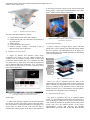
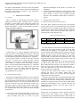
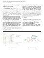
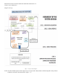
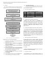
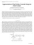
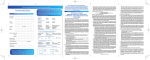
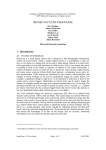
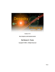
International Journal of Scientific and Research Publications ISSN 2250-3153 Volume 3 Issue 3 March 2013 An Interactive Infrared Sensor Based Multi-Touch Panel Vasuki Soni, Mordhwaj Patel, Rounak Singh Narde Department of Electronics and Telecommunication Engineering National Institute of technology, Raipur Raipur, Chhattisgarh Abstract: This paper contextualizes an idea of implementing an Interactive touch sensitive user interface. It is an optical touch sensing technique and architecture that allows precision sensing of hands, fingers, and other objects within a constrained 2-dimensional plane. This paper gives the details of the touch panel - a hardware and software based architecture for multi-touch sensing. This is a flat-panel optical multi-touch scheme using a linear array of modulated light receivers which surround the periphery of a display to detect touch. It is a point-to-point visual hull sensing technology, meaning it uses much of modulated infrared sensors and many IR LEDs [4] (940nm) to create a series of invisible light beams that cross the screen. When these beams are being interrupted, it means something has touched the screen, and we can visualize interruption of the beams to reconstruct the visual hull of any objects inside the sensor frame. This way the touch interrupt occurred is first transformed into an image with several scan lines and then many such images make a video clip (which contains the information of the touch point/ Blob) which is then interfaced with the Image processing software for the Blob detection [15] and Mouse cursor control [17]. Keywords: CCV(Community Core vision), IR(Infrared), FPS (Frames per second), LCD (Liquid crystal display), AVI(Audio video interface), USB(Universal serial interface), ARM(Advanced RISC Machines), TUIO(Tangible user interface), NUI(Natural User Interface). I. INTRODUCTION AND MOTIVATION This technology presents an idea that is basically dedicated to the field of Education. In our day to day life, we see that in the field of education, it involves more user interaction for better understanding. In the village areas and in many schools/ colleges, this has been the requirement that the education needs to be more interactive. But simply due to the lack of resources, it is not yet been possible for us to provide such a solution which is affordable at the Village Level. So the touch technologies now come-up to show innovation in the same. This application provides a visual touch sensitive interface to the Computer operated device by which user without touching the mouse can easily operate it. Just imagine a person moving and zooming images on a screen, not by mouse but by his fingers. All this is possible after having implemented, the interface explained as above. The main goals of this project were to do the following improvements: 1. 2. 3. 4. 5. Ease of handling and affordability at village level. Reducing the size of the whole assembly. Power consumption reduction. Reducing the processing delay. Good frame rate. A. Technical Background This implementation is an inspiration from the series of technologies presented in the near past. Microsoft introduced Microsoft Surface which uses the Infrared camera to sense the Blob/Touch Points. Another one was presented by Microsoft which was used in the “Thin-Sight”–A Multi Touch technology [2], in which the developers have made the touch sense panel using the Infrared Sensors lying all over the surface of the Touch Sensitive Plane to achieve Multi–Touch Feature. We hereby use the idea and bring a change in the former idea by reducing the number of sensors used by using the sensors only along the periphery of the surface and not covering the whole surface. Many more like Microsoft Pixel Sense and the Touch User Interface made by NUI Group using CCV (Community Core Vision) software. These inventions and technologies had their efficient contribution towards the recognition of the touch technologies in the modern world. B. Prior Art 1) Microsoft Surface 1.0 It is a 30 inch (76 cm) 4:3 rear projection display with integrated PC and five near-infrared cameras that can see fingers and objects placed on the display from below. The cameras vision capabilities enable the product to see a near-IR image of what is placed on the screen, the image is then captured at approximately 60 Frames per second (FPS). The Surface platform processing could recognize fingers, tags, and blobs. Figure -1 below shows the Microsoft Surface table and its inner configuration. www.ijsrp.org International Journal of Scientific and Research Publications ISSN 2250-3153 Volume 3 Issue 3 March 2013 to the image processing software for the optical touch based control. Figure -3 below shows the implementation of the ThinSight [2] (Borrowed from Microsoft Research). Figure – 1: Schematic of Microsoft's Surface The parts of the surface table are as follows: a) Acrylic tabletop touch surface with a diffuser. b) 850nm infrared light source directed at the underside of the touch surface. c) Infrared camera. d) Texas Instrument’s DLP projector. e) Desktop computer running a customized version of Microsoft Vista. Source: Microsoft. 2) Community core vision (CCV) Figure – 3: Thin Sight technology (Surface of touch filled completely with the sensors and above it are the detected blob / touch points) 4) Microsoft Pixel-Sense It allows a display to recognize fingers, objects and hands placed on the screen, enabling vision-based interaction without the use of cameras. The individual pixels in the display see what's touching the screen and that information is immediately processed and interpreted. A Project by Natural User Interface (NUI) Group Community Core Vision is an open platform solution for computer vision and machine sensing. It takes an video input stream and outputs tracking data (e.g. coordinates and blob size) and events (e.g. finger down, moved and released) that are used in building multi-touch applications. CCV can interface with cameras and video devices as well as connect to various TUIO enabled applications. Figure – 4: Microsoft Pixel-Sense But as it is easy to understand from the details of the implementations above that either Infrared sensors used were in bulk or Cameras were implemented. So we have optimized the design by working over the parameters such as reducing the number of sensors, size of overall hardware, Processing Delay, Frame Rate, Power dissipation, Ease of handling etc. Figure – 2: Screenshot of the CCV Software shows the detection of blob (right) and image seen by infrared camera (left) 3) Thin-Sight A Multi touch detection approach by Microsoft Research uses the lots of sensors lying on the surface of the touch panel. This sensor matrix is placed just behind any LCD display so as anyone places its finger over the LCD screen the light is reflected back and the position of the touch is then transferred C. Organization of the report This paper is organized in the way as explained further. Section- I is the fundamental introduction to the importance of touch technology in relation to our project and the previous work, Section-II describes the problem focused in this project Section II-B gives the detailed timeline of the project implementation. Section II-D describes the hardware implementation and Section II-E on the other hand describes International Journal of Scientific and Research Publications ISSN 2250-3153 Volume 3 Issue 3 March 2013 the software implementation. Section III states the problems and tradeoffs. Section IV presents results of the simulation and the testing and presents an analysis on the performance characteristics of the system. II. PROBLEM STATEMENT A. Concept This is a concept of visual interface which deals with the application of the linear array of Infrared sensors [5] along the periphery of a panel which can be made touch sensitive. We need to provide a system which can digital interface to the Stimuli. In the Figure - 5 below, we just attempt to picturize a concept of interactive education. dissipation/consumption for the whole lot of sensors and transmitters. 2) Another important parameter that is the processing delay of the system; is also reduced as the number IC’s and driver circuitry as well as data acquisition circuitry required is also considerably reduced due to reduction of sensors. C. Detailed timeline of the project 1) Preparation of the Sensor panel for Touch The sensor panel comprises the major part of the Sensing circuitry. These sensors are connected along a line to form the two opposite sides of a rectangle just like that of a Laptop or a computer screen. These sensors are built in the form of modules which contain 8 sensors and an IR LEDs. These LEDs are actuated not all at a time but one by one. TABLE-1 Infrared LED and Receiver S. No 1 2 Component Infrared RX Infrared TX Product TSOP-1738 IR-908 Manufacturer Vishay Everlight 2) Sensor data acquisition Figure – 5: Interactive education In this project we are using an algorithm to first detect the touch point and its corresponding blob using the sensor data received using a USB Interface and we are creating an image from that data using Image Processing library in C-Language. Now using these frames we create an AVI video file .This video file is utilized by the image processing software Community Core Vision-CCV (from NUI Group) - An open source solution for computer vision and machine sensing. It takes a video input and outputs tracking data (e.g. coordinates and blob size) and events (e.g. finger down, moved and released) that are used in building multi-touch applications. This way we achieve the touch sense as well as the corresponding mouse movements. B. Prior Work and Learning In the previous implementations that were seen in Section I-B reveal that the use of Infrared transceiver pair can be efficiently done in the domain of touch detection. As in Thin-Sight [2] and Microsoft Pixel Sense [21] we saw that infrared sensors were used, but sensors all over below the surface of touch; were quite large in number and may increase in their number further with the increasing need of the resolution. So we in our design have optimized the touch sense panel and found following improvements. 1) First of all we have reduced the number of sensors as we are using sensors only along the periphery of the touch panel. Secondly hence also we reduce the power The touch detection system works on the principle that finger placed in the touch panel obstruct the path of the IR Rays emitted from the periphery of the panel. Due to this the receivers change in their outputs after the reception of reflected IR Rays. The IR Sensors are basically actuated by the 38 KHz Modulated signal to stand out of the noise. At a time only single IR LED is activated using the combination of D – Flip Flop and Tristate buffer which provides accurate clock and synchronized switching of LEDs. When the touch event takes place on the panel obstructing the path of the IR LED, some sensors do not receive the IR Rays emitted from the LED due to the obstruction caused as above. So we get a type of image as shown below in Figure – 7. Now after data retrieval is our next concern. Now we are having 96 sensors and 12 IR LEDs. But for the data retrieval from sensors we don’t have sufficient I/O pins in the Stellaris ARM Cortex M3 microcontroller. Hence we are using the Shift Registers (SN74165) to increase the I/O pins. The data is then collected by the 8-Bit Parallel Input Serial Out (PISO) Shift Register. This serial data coming from each shift register in each sensor module (having 8 IR Sensor and 1 IR LEDs) are padded serially in the bit stream which finally reaches the microcontroller and is received using the SSI (Synchronous Serial interface). Now the data is ready for further processing. 3) USB Based Serial Communication with microcontroller Moving next, our requirement is then to send the data bytes received from each module to the computer. This is accomplished using the USB Based transfer. This transfer is a serial transfer which is carried out using C language supported International Journal of Scientific and Research Publications ISSN 2250-3153 Volume 3 Issue 3 March 2013 by the functions in the (LIBUSB.H) certified by GNU. We are using Bulk Transfer scheme because the data in the form of an image (as in Section III-A-4) has to been sent over USB, which is a Long Burst data for which the Bulk transfer is basically meant for. So it is very useful for us in this step. 4) Implementing C Language for the Image creation using the Sensor Matrix data The data retrieved in the previous step is now utilized for the Image creation which will give us the pictorial representation of where actually in the 2-D Plane of Touch panel was the touch detected. This is done using the C Programming. The (bmp.h) [23] is a header file which allows us to create, modify, and write BMP image files. This image is actually made by creating scan-lines i.e. line between a receiver and transmitter made when the communication between them is successful and these scan-lines are made in the image for each possible Rx-Tx pair in the sensor matrix. A sample image made during our implementation using dummy data in which every possible Rx-Tx pair is communicating successfully as no touch / obstruction is present is shown below in Figure – 6. Figure – 7: Finger touch on the panel obstructing the path of IR rays for one IR LED. 6) Creating Video interface with CCV–Community Core Vision Up to this stage we have a video which now is capable of showing where actually the touch was detected (i.e. Blob) with respect to the Sensor Matrix Frame. This information at this stage is now very useful as these videos are ready to be interfaced and fed to the Image Processing software: CCV– Community Core Vision [15] - this software takes the video input stream made by the frames of blob detection images as in Section II-C-4 from touch panel and outputs the tracking data which is useful for mouse movements. So we now have the video being interfaced with the software and now required is a software driver which can synchronize the blob position figured out by CCV [15] with the mouse movements. 7) TUIO Mouse Driver Implementation[17] Figure – 6: Scan Lines created when no finger was placed with all LEDs ON 5) Creating AVI(Audio video interleave) Video file from the frames (Images of scan-lines) obtained We are now ready with the sensor data and frames of images obtained in Section III-A-4. Now we are ready to make a video (AVI Video) by using the frames. Now in case of a Touch sense on the touch panel, for each LED there is generated one image as in Figure- 7 and the required frame is the one obtained by the sensor data (refer Section III-A-4) corresponding to all LEDs actuated because actuation of each LED will create a frame but the final image is that which is obtained after overlapping all the frames obtained corresponding to each LED lit which will contain a Touch Point visible and all other space is and many such final images are required to make a Video file. This algorithm is implemented using (bmp.h [23] and avi.h[24] ) header files and is written for the purpose of converting bmp files to AVI Video . Figure – 7, RED Spot shows the IR LED and the Black semicircles denote the IR Receivers. TUIO is an open framework and platform to support the tangible user interface. The TUIO allows the transmission of meaningful information extracted from the tangible interfaces including touch events and object specifications. This protocol enciphers the control data from a tracker application (e.g. based on computer vision) and sends it to any client algorithm that deciphers this information. This combination of TUIO trackers, protocol and client implementations allow the rapid development of tangible multitouch interfaces. Finally we are now at a stage to successfully run our Touch user interface having mouse moves well synchronized with the Finger movements and gesture. D. Hardware 1) Overview The hardware of the project can be broadly classified into two major blocks as stated in the previous sections. One is the Data acquisition circuitry, the other one is the processing and the third one is the User Interface unit. The Data acquisition block can be further sub-divided into Sensors (for sensing the touch interrupt) and the Shift Registers (for receiving data from sensors). The communication part is handled under USB International Journal of Scientific and Research Publications ISSN 2250-3153 Volume 3 Issue 3 March 2013 protocol. The rest part constitutes the User Interface i.e. the multi touch panel which directly interacts with the User. The following Section III-C-2 will give us a better understanding of the system design. 2) System design and Hardware requisites The system assembly involves a lot of hardware and their interconnections. The IR LED used in our project is IR-908 High Intensity Diode with 60o radiance angle[4] because we know that IR rays emitted in the touch panel should cover maximum angle so as to cover as many sensors as possible to make the touch detection more sensitive and accurate hence increasing resolution. We have seen in the Section III-1-2 that the IR Led requires a modulated signal for the its proper working. Previously we planned to use NE-555 timer for the timing pulse generation but the circuitry could have been more bulky unnecessarily. So it was a better option to use timer of the Microcontroller supplied through a combination of D-Flip Flop [9] and Buffer [7] to provide a pulse of required frequency i.e. 38KHz to the IR LEDs as it avoids the problems regarding the voltage fluctuation also and reduces the hardware connection as unlike 555 timer it does not require extra connections to furnish a timing circuitry. This signal is going to be received by TSOP1738: An IR Sensor which detects signals modulated (with some schemes like RC5, NRZ, Manchester coding) with 38 KHz frequency. Thus this unique detection technique makes the selection of the Sensors and LED quite profitable and brought us good results in terms of sensitivity. Figure – 8: Infrared sensor array The processing unit constituted by Stellaris ARM Cortex M3 is a high speed controller that operates at appreciably high speed of 80MHz with 100 DMIPS which is too good for the performance of our system because we have to handle the making of image from the sensor data, and then those images will create video as seen before. Now then after we need to use the video for making synchronism with mouse movements using procedure as in Section II-C-6 and Section II-C-7. This whole task is enough to provide a sufficient processing delay, thus deteriorating the reliability of the touch detection system. So by considering speed as a factor, Stellaris ARM Cortex M3 was really an intelligent choice. One more point of advantage that it has that there are lots of serial communication channels and many GPIO are also present, so interfacing limitations never came on our way. 3) Schematics This section shows the two schematics of the sensor module and the IR LED which form the Touch Panel. Figure – 8 shows the Infrared sensor array with 8 Infrared sensors placed in an array and is connected to a Shift register [8] which takes the 8 bit data from the array of sensors and output them to the microcontroller in the serially padded bits. Figure – 9 shows the Infrared LED supplied with a 38 KHz signal from microcontroller using the PWM channel through the D Flip Flop [9] and Tri state bus buffer [7]. Figure – 9: Infrared Emitter / LED International Journal of Scientific and Research Publications ISSN 2250-3153 Volume 3 Issue 3 March 2013 4) High level design Figure – 10: Top level block diagram NOTE: The Sensor Module depicted in this diagram is just a single module. Many modules combined altogether in daisy chained architecture constitute Touch Panel (Refer to Figure – 11). International Journal of Scientific and Research Publications ISSN 2250-3153 Volume 3 Issue 3 March 2013 5) Physical arrangement of the Touch panel a) Touch Panel : The touch panel shown below in Figure – 11 shows the sensor based touch panel which consists of many Sensor Modules each having one IR LED and 8 – IR Sensor. The 8:1 ratio between receivers and LEDs was chosen as a compromise between spatial and temporal resolution. Figure – 11 : Touch Panel NOTE: The touch panel shown does not show the details of connections; rather is just helpful in getting an idea of how actually the touch panel looks and the arrangement of sensors/LEDs with respect to the screen. International Journal of Scientific and Research Publications ISSN 2250-3153 Volume 3 Issue 3 March 2013 E. Software The software foundation and flow of system processing is organized in way as given in the below flow chart Figure -12. Furnishing the Infrared LEDs with 38KHz modulated signal with the DFlip Flop and Tristate buffer Extraction of data from Sensor array using Shift Register j) Clear BMP buffer variable. k) Check if the maximum limit of the frames to be sent is exceeded. If YES, then END else move to the (Step h). This way the process repeats. F. List of the components required TABLE – II List of the components used Component Manufacturer SN74LS165A Texas Instruments S.No 1. 2. 3. 4. 5. SN74175 SN74125 UA 7805 Stellaris ARM Cortex M3 Texas Instruments Texas Instruments Texas Instruments Texas Instruments III. Problems and Trade-Offs Synchronous Serial Interface for receiving data coming from Shift Registers and providing clock to shift registers USB based transfer (Bulk Transfer) Creating scan lines using the sensor data and then an image frame A. Common Issues in Optoelectronic Sensing. Among the wide variety of techniques for optoelectronic touch sensing, most of them suffer from a few common problems which can interfere with a system’s success due to the improper working of the ambient light sensitivity is perhaps the most important noise factor in optoelectronic multi-touch systems, followed by active light interference. B. Clocking of the hardware and bit rate of data acquisition Creating Video from the image frames obtained from the sensors Configuring CCV and TUIO driver for the Mouse control STOP Figure – 12: Flow chart for software implementation 1) Brief steps for the system implementation a) b) c) d) e) f) g) h) i) Initialization of the memory and the initial status for the IR LED and IR Sensor data. Initialize the AVI_T – a variable for AVI Output file and also the BMP Structure for the handling the creation of the BMP File. Initialization of Library “libusb.h” for the USB transfer (refer to Section II-C-3). Now check if the device that is to be transferred data is connected through the proper Vendor ID and Product ID, if yes then move forward else check again. Open file (AVI File) for the output. Set video with width, height, Frames per second (FPS) and compressor length. Clear the BMP Call a subroutine to draw scan line on the BMP Frame. Call a subroutine to convert bmp to AVI frame. The clocking of the hardware ICs and other circuitry is point of great concern as well as the bit rate settings because these parameters need to be set properly for the peripheral interfacing. If there is a mismatch or improper clock given to the hardware such as Shift Registers, D- Flip Flop and Buffer, this will prevent the system from doing efficient data acquisition and also will lead to loss of much data due to asynchronous operation. C. Increasing current load and voltage drop In this design when the sensor modules were tested independently, there was no problem with the outputs they gave; but when all the sensors were operated simultaneously , they drew such an amount of the current that it was not possible for the sensors to sense and give proper output to be detected. Hence as learning, we understood that a high current drive could be used according to the rating of the sensors for their proper working. IV. Results So after a detailed analysis and final testing of the project, following test results were appearing: A. Performance analysis The performance of the touch prototype seemed to be sufficiently good and has a fairly good resolution also but the International Journal of Scientific and Research Publications ISSN 2250-3153 Volume 3 Issue 3 March 2013 sensitivity of touch was found slightly week at the edges of the panel formed by the sensor assembly. The accuracy of the touch actually depended on the angle of dispersion of the IR Rays furnished by the IR emitter. As this angle increases, the part of the screen that is sensible to touch also increases. The Infrared emitters/LEDs in our design use forward current of 20-50mA, so one factor was to look at the powerful voltage and current supply for them. B. Functional testing During the testing and PCB design, we were aware of the fact that the IR LEDs would require large current. So as for the touch detection we had to switch ON the LEDs, but if all the LEDs were ON simultaneously then a lot of current could have been drawn from the power source, which would let a large power to be dissipated. Hence we decided in our design to let the LEDs be switched ON one by one. Hence we got rid of the problem. The performance data was analyzed as follows: Resolution: The touch panel gave a good level of sensing for a Laptop sized panel of 15.6 inches. Power: The power in this system was found to be optimizable as the clock management feature in the Stellaris ARM Cortex M3 has the ability to switch between the high frequency clock to low frequency clock to offer sleep modes / low power modes. Processing delay: This parameter was basically affected by the algorithm implemented and proper serial communication and synchronism. The improvement of this parameter depends on the Clock management and the Bit rate for the serial communication. Frame rate: This needs to be set by the user and is generally limited by the capabilities of the processing unit like the rate of the sensor data reading. The size of the hardware may vary according to the size of the display 5. Conclusions A. Summary The importance of this project is that we have tried to implement an easy to use, portable and cheap multi touch panel. This has special meaning for students who are aloof from an Interactive Education system just due to lack of handsome amount in their pockets. The device is affordable by almost every village level offices and schools. This is going to be profitable because its packaging and assembly doesn’t allow unnecessary interference in the normal working of the touch panel. This final project is successful with most of the objectives and goals fulfilled. We believe that the prototype presented in this paper is an effective proof of concept of a new approach to multi-touch sensing for thin displays. We have shown that how this technique can be integrated with Optical display such as computer/laptop screen. The optical sensing allows potential for rich data to be captured by the display and processed using computer vision techniques [15]. This allows new type of human computer interface that exploits multi-touch and tangible interaction on displays, making such interaction techniques more practical and deployable in real-world applications. We have tried to expand the sensing area to cover the entire display, which has been relatively straightforward given the scalable nature of the hardware. In addition to such an incremental improvements we are also exploring new applications and interaction techniques that can truly benefit from multi-touch, multi-user and tangible input. Thus our project can be implemented better using multi-touch interaction for education purposes making such activities more intuitive, engaging, social and fun. B. Completeness of the project This project is complete in the sense of application areas where the sensitivity and resolution are not a big issue at all like school education in villages where only the students have to be taught big letters, shapes, pictures and moving or controlling those using fingers. But this project due to its easy structure was not built taking more resolution into consideration as the algorithm implemented to detect touch allows us to detect touch almost finely. So for the purpose of the advanced application like mobile and interactive displays we need to work more on the resolution. C. Need for the further optimization We need to work more on the hardware like in our system we found that if the IR sensors that are TSOP 1738[5] were more small the resolution of the system could have been improved in terms of the touch sensitivity in a better way. We can also try to extend the scope of our software implementation to eliminate the need of the software platform like CCV [15]. D. Market value of the product The product needs a good packaging and needs to be slim more. So the product at this level is sufficient in the design point of view and satisfies basic need of a Human computer interaction (HCI) but needs more modeling to hold a good position in the market. E. Feasibility The Touch panel is very easy to use and handy because it is nothing but just a flat panel builds around an array of sensor. This just needs to be fit on the front of surface we intend to International Journal of Scientific and Research Publications ISSN 2250-3153 Volume 3 Issue 3 March 2013 make touch sensitive like a Computer monitor screen. Low cost of installation and less human interference makes it more user friendly and easy to use. Hence we can expect a good future of such implementation for the domain of Interactive Education which is our main point of concern. One can think that in the bulk production of such modules, the project cost can be further minimized. Hence it is a profitable, adaptive, affordable and most primarily a feasible solution for the purpose of the Interactive Education as stated in this paper. 3) Form Factors Because this touch modules can be arranged into in any number of form factors, possibilities abound. One interesting form factor is using two strips of sensors to create a multi-touch or free-air interaction. There is no need to create a complete polygon of sensors, as the one-to-many relationship between receivers and LEDs enables multitouch sensing even without enclosing the sides of the sensor. APPENDIX – A F. Future work 1) Sleep modes PCB Design for the Sensor Module These are the modes of the activity to control the power consumption. These include the switching off the main clock and running the system on low frequency clocks in case of the system being left on hold / system is in unused state for a sufficient time. As soon as the touch interrupt is detected, the clock management automatically gets transferred to the main clock (High frequency clock) and the power is switched on. 2) Three Dimensional Sensing Future work may investigate 3-D Interaction. By using Infrared modules in non-planar configurations, three dimensional visual-hull sensing is possible. This can be accomplished by stacking multiple planar layers or by using non planar arrangements in any configuration. It has the potential to provide precision for smaller interaction areas. The PCB Designing has been done in CAD Software EAGLE v 6.1. This board consists of the 3 Sensor Modules assembled together each having 1 Infrared LED at the front of the board and 8 infrared sensors just behind in a linear array. Each 8 sensor assembly is connected to a Shift register [8] and the LED at the front is supplied frequency of 38 KHz from the timer of Microcontroller and is supplied through a D-Flip Flop [9] and a Tristate Buffer [7]. The blue lines on the below PCB Layout show the copper track to be printed. The Red lines denote the Jumper. The Green pads are the Drillable points like IC Pins, BurgStrip pins. Figure - 13 PCB Design Layout for the Sensor Module International Journal of Scientific and Research Publications ISSN 2250-3153 Volume 3 Issue 3 March 2013 APPENDIX B – Bill of Materials List of the components used in our design are as follows: Table – III Bill of Materials S.No. Component Manufacturer 1. 2. 3. 4. 5. 6. SN74LS165A SN74175 SN74125 UA 7805 Stellaris ARM Cortex M3 TSOP 1738 Total cost Texas Instruments Texas Instruments Texas Instruments Texas Instruments Texas Instruments Vishay Total cost (in Rupee) 276 140 104 108 750 1000 INR 2378/- REFERENCES Background Papers / Journals: [1] [2] [3] Hrvoje Benko, Andrew D. Wilson, Patrick Baudisch: “Precise Selection Techniques for Multi-Touch Screens”: CHI 2006 Proceedings Interacting with Large Surfaces, April 22-27, 2006 Montréal, Québec, Canada . Shahram Izadi, Steve Hodges, Alex Butler, Alban Rrustemi and Bill Buxton: “Thin-Sight: Integrated Optical Multi-touch Sensing through Thin Form-factor Displays”, Microsoft Research Cambridge, 2007. Hofer, R., Naeff, D. and Kunz, A. 2009. FLATIR: “FTIR multi-touch detection on a discrete distributed sensor array” Proc. TEI 2009. Datasheets: IR 908 – Infrared LED : User manual http://www.embeddedmarket.com/storeresources/NN264/user%20manual.pdf. [5] Tsop-1738 : Infrared sensor - Vishay http://www.datasheetcatalog.org/datasheets/208/ 301092_DS.pdf. [6] STELLARIS ARM CORTEX M3 LM3S9D92 Texas Instruments www.ti.com/lit/ds/symlink/lm3s9d92.pdf. [7] SN74125:Quardruple bus buffer with tri state output http://www.ti.com/lit/ds/symlink/sn74ls125a.pdf. [8] SN74165 : Parallel-load 8-bit shift registers http://www.ti.com/lit/ds/symlink/sn74165.pdf . [9] SN74175 : Hex/quadruple D-type flip-flops with clear http://www.ti.com/lit/ds/symlink/sn74175.pdf. [10] AVR410: RC5 IR Remote Control Receiver [4] Library / Header files borrowed: [22] [23] [24] [25] USB header file - libusb.h: www.libusb.org. BMP Library file - bmp.h: http://zsmith.co/bmplib.html. AVI Library file – avilib.h: http://www.networkmultimedia.org/current/Docs/D oxygen/html/avilib_8c.html ACKNOWLEDGMENT The authors would like to thank Prof. B. Acharya, Head of the Department, Dept. of Electronics and telecommunication engineering, for guiding us and reviewing our paper. AUTHORS 1) Vasuki soni Student B-Tech (Bachelor of Technology) Dept. of Electronics and Telecommunication Engineering National Institute of technology, Raipur Raipur, Chhattisgarh, India E-mail: [email protected]. 2) Mordhwaj patel Student B-Tech (Bachelor of Technology) Dept. of Electronics and Telecommunication Engineering National Institute of technology, Raipur Raipur, Chhattisgarh, India E-mail: [email protected] 3) Rounak singh narde Student B-Tech (Bachelor of Technology) Dept. of Electronics and Telecommunication Engineering National Institute of technology, Raipur Raipur, Chhattisgarh, India E-mail: [email protected] Product Vendors: [11] Texas Instruments: http://www.ti.com. [12] All sensors : http://www.allsensor.in. Websites and Documents: [13] SSI : Synchronous serial interface http://en.wikipedia.org/wiki/Synchronous_Serial_Interface. [14] USB (Universal serial bus) : Wikipedia http://en.wikipedia.org/wiki/Universal_Serial_Bus. [15] Community Core Vision [CCV] –NUI Group: http://ccv.nuigroup.com. [16] GIT Hub: http://www.github.com. [17] TUIO: http://www.tuio.org/. [18] USB In a nutshell: www.beyondlogic.org/usbnutshell/usb4.shtml . [19] Microsoft Surface – http://www.surface.com. [20] Seth Sandler: Multi touch - How to?. http://sethsandler.com/multitouch/. [21] Microsoft Pixel Sense http://www.microsoft.com/enus/pixelsense/pixelsense.aspx. ---------------------------------------------------------- International Journal of Scientific and Research Publications ISSN 2250-3153 Volume 3 Issue 3 March 2013