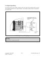
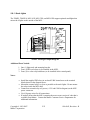
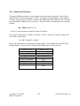
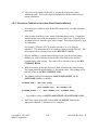
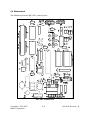
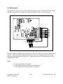
1
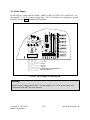
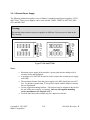
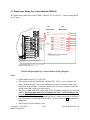
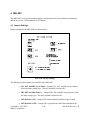
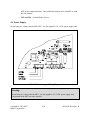
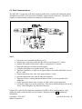
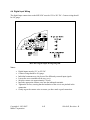
ProHelp® EPM
Production & Process Monitoring System
MIU Wiring and Installation Manual
For ProHelp® EPM, Release 7.5
MANUAL #810-0043
Revision – R
December 4, 2007
ATTENTION
You can obtain service support by visiting Mattec’s web site at http://www.mattec.com, by
emailing the help desk at [email protected], or by telephone at (513) 683–1802.
This manual is intended for advanced users only.
Copyright © 1983-2007
Mattec Corporation
1-2
810-0043, Revision – R
TABLE OF CONTENTS
1.
Introduction........................................................................................................................ 1-5
1.1 System Components ....................................................................................................... 1-6
1.1.1 Server Computer ...................................................................................................... 1-6
1.1.2 Machine Interface Unit (MIU)................................................................................. 1-6
1.1.3 PLC Interfaces ......................................................................................................... 1-6
1.1.4 RocketPort Serial Communication Board And Buffer Box..................................... 1-6
1.1.5 Client Computers ..................................................................................................... 1-7
1.2 Shut Down Procedure..................................................................................................... 1-7
2.
TSMIU, TSMIU-0, MIU-10X, MIU-5XS, MIU-0XS....................................................... 2-8
2.1 Jumper Settings............................................................................................................... 2-9
2.2 Switch Settings ............................................................................................................. 2-11
2.3 Power Supply................................................................................................................ 2-12
2.3.1 External Power Supply .......................................................................................... 2-14
2.4 Host Communications .................................................................................................. 2-16
2.5 Digital Input Wiring ..................................................................................................... 2-18
2.6 Digital Input Wiring (TSMIU-0).................................................................................. 2-19
2.7 Digital Input Wiring, Dry Contact Method (TSMIU-0)............................................... 2-20
2.8 Digital Output Wiring................................................................................................... 2-22
2.8.1 Stack Lights ........................................................................................................... 2-23
2.9 Analog Input Wiring..................................................................................................... 2-24
2.9.1 Analog Gain Resistors ........................................................................................... 2-25
2.9.2 Calibration.............................................................................................................. 2-27
2.9.3 Thermocouples Calibration Procedure .................................................................. 2-28
2.9.4 Transducer Calibration Procedure (Shunt Resistor Method)................................. 2-29
2.9.5 Transducer Calibration Procedure (Machine Gauge Method)............................... 2-30
2.10
PLC Wiring ............................................................................................................... 2-31
2.11
AIU Wiring ............................................................................................................... 2-32
2.12
Motherboard .............................................................................................................. 2-33
2.13
Product Specifications............................................................................................... 2-34
3.
MIU-Z1 ............................................................................................................................ 3-35
3.1 Settings ......................................................................................................................... 3-36
3.2 Power Supply................................................................................................................ 3-37
3.3 Host Communications .................................................................................................. 3-38
3.4 Digital Input Wiring ..................................................................................................... 3-40
3.5 Digital Output Wiring................................................................................................... 3-41
4.
MIU-9DC......................................................................................................................... 4-42
4.1 Jumper Settings............................................................................................................. 4-42
4.2 Power Supply................................................................................................................ 4-43
4.3 Host Communications .................................................................................................. 4-44
4.4 Digital Input Wiring ..................................................................................................... 4-45
4.5 Digital Output Wiring................................................................................................... 4-46
4.6 Motherboard ................................................................................................................. 4-47
5.
MIU-DC12....................................................................................................................... 5-48
Copyright © 1983-2007
1-3
810-0043, Revision – R
Mattec Corporation
5.1
5.2
Switch Settings ............................................................................................................. 5-48
Motherboard ................................................................................................................. 5-49
6.
Buffer Box ....................................................................................................................... 6-50
6.1 MIU to Buffer Box Wiring (Green Connector)............................................................ 6-50
6.2 Buffer Box to Computer Wiring................................................................................... 6-50
Copyright © 1983-2007
Mattec Corporation
1-4
810-0043, Revision – R
1. Introduction
Mattec Corporation's ProHelp® EPM Production and Process Monitoring System is specifically
designed for real-time monitoring of all types of production equipment. It is used extensively in
the plastics injection molding, extrusion, blow molding, blown film, metal stamping, die casting,
printing, painting, and assembly industries. The basis behind the benefits from the
ProHelp® EPM system is the rationale that plant managers and operational people will take
corrective actions to solve problems on production equipment when they are aware of such
problems. ProHelp® EPM is the device to alert employees to problems immediately when the
problems occur. Therefore, tremendous savings can occur in increased productivity and
decreased scrap parts.
The ProHelp® EPM system combines computer hardware, computer software, and Machine
Interface Units (MIUs) into an efficient system to provide real-time production monitoring,
production reports, process alarms, plant scheduling aids, and SPC/SQC process and part
capability analysis. Floor personnel can make use of the machine-mounted terminals to signal
different departments for help, to view production results at the machine site, and to enter
downtime reasons or scrap reasons. Production, downtime, and scrap reports can be generated
on a shift and daily basis, or the user can generate these reports for extended time periods by
specifying a start and end date for the desired report. Job history data is continuously
summarized and available for management's review.
This manual describes how to install different versions of MIUs. It is intended for advanced
users only.
Copyright © 1983-2007
Mattec Corporation
1-5
810-0043, Revision – R
1.1 System Components
The following sections provide a brief overview of those components that comprise the
ProHelp® EPM system.
1.1.1 Server Computer
The main ProHelp® EPM computer is referred to as the “server”, “host”, or “monitoring node”
computer. This is the only computer that is required to run the ProHelp® EPM system. This
computer contains all of the configuration files, data files, and ProHelp® EPM software.
The server computer runs Microsoft’s Windows Server 2003 operating system and Microsoft’s
SQL Server 2005 database.
All MIUs connect to the server computer. All data from MIUs is automatically recorded at the
server and can be viewed from other computers in real-time.
1.1.2 Machine Interface Unit (MIU)
The Machine Interface Unit (MIU) is an industrial-strength data collection device that has been
designed and manufactured by Mattec. It is used to collect production and process information
from the manufacturing machine and transmits that data in real-time to the server computer.
There are a wide variety of MIUs. Most have a graphical interface that allows the machine
operator to view data about the current job and input relevant information (e.g., scrap parts).
Many MIUs have both analog and digital inputs. Many MIUs have an optional PLC interface
that can be used to extract data directly from supported machine controllers.
1.1.3 PLC Interfaces
Many MIUs are capable of optionally extracting information directly from the machine’s
programmable logic controller (PLC).
PLC wiring connections are described in this manual. For additional information regarding
software configuration for PLC interfaces, reference the PLC Subsystems Manual, #810-0078, on
Mattec’s website.
1.1.4 RocketPort Serial Communication Board And Buffer Box
MIUs are connected to the server computer via RS-485 cabling. Typically, up to 16 MIUs can
be daisy-chained together on a single channel. Multiple channels can be used in order to reach
the maximum 4,096 MIUs per system.
The Buffer Box is a small, 4-channel device that has been designed and manufactured by Mattec.
It is usually located within a few feet of the server computer. The Buffer Box converts the RS485 signal to an RS-232 signal and “conditions” the signal.
Copyright © 1983-2007
Mattec Corporation
1-6
810-0043, Revision – R
A channel of MIUs (RS-485) is wired into the Buffer Box on one side. On the other side, the
Buffer Box outputs an RS-232 signal that is connected to a serial communication port on the
server computer.
In most applications, Mattec will have installed a RocketPort Serial Communication Board in the
server computer. The RS-232 signal from the Buffer Box is connected to one of the channels on
the RocketPort board. The RocketPort board contains multiple communication ports and is a
“smart” device that improves the communication process.
1.1.5 Client Computers
Although the server computer is a fully functioning “client” system, most users will want to
connect to the system from their own computer. To do so, they will need to have an approved
Microsoft operating system loaded on their computer. The System Manager will load the
ProHelp® EPM Client software on that computer and configure it to connect to the server
computer. The user will be given permissions to access or modify data, as appropriate.
These users with then be able to view data for the entire facility in real-time.
1.2 Shut Down Procedure
ProHelp® EPM is intended to run 24 hours per day, every day. When it does become necessary
to reboot the system, use this procedure. It will bring the system to an orderly shut down.
•
Announce to all users that you will be taking the system down. Have all users exit
the ProHelp® EPM software.
•
Assure that no ProHelp® EPM job changes are under way.
•
Assure that a shift change is not in progress.
•
Login to the server computer as an authorized user.
•
Using the mouse, click on the Microsoft Windows Start Menu and select Shut
Down. The Shut Down Windows dialog box will be displayed.
•
Select Shut Down the computer? and press Ok.
Copyright © 1983-2007
Mattec Corporation
1-7
810-0043, Revision – R
2. TSMIU, TSMIU-0, MIU-10X, MIU-5XS, MIU-0XS
Many of Mattec’s more advanced MIUs are based on the “10X98” motherboard, including:
•
TSMIU – The TSMIU is a color, touch screen MIU that has optional analog
inputs and an optional PLC interface.
•
TSMIU-0 – The TSMIU-0 is a color, touch screen MIU that is capable of
monitoring 2 to 16 machines. It has optional analog inputs but can not have a
PLC interface.
•
MIU-10X – The MIU-10X is an MIU with optional analog inputs and an optional
PLC interface. It has a 16 by 40 character LCD display.
•
MIU-5XS – The MIU-5XS is an MIU with an optional PLC interface. Some of
these MIUs can be upgraded to an MIU-10X while others can not be upgraded to
an MIU-10X (i.e., can not have optional analog inputs). It has a 16 by 40
character LCD display.
•
MIU-0XS – The MIU-0XS is an MIU that has digital input monitoring only for 2
to 16 machines. It has a 16 by 40 character LCD display.
Warning:
Do not bring AC voltage into the MIU. Use the supplied +5/-5/+12/-12 DC power supply
only. Components in the MIU are static sensitive. Do not remove the MIU’s battery.
Diagnostics
When the TSMIU is restarted, it will display a large Mattec logo until it is configured. You can
press the Mattec logo to go to the Service Display. This will allow you to configure settings that
are used by the MIU to communicate with the host computer.
When an LCD MIU is started, is will display the message PRESS ANY KEY FOR
DIAGNOSTICS. Simply press a key on the MIU to enter the configuration and diagnostics
mode. When the MIU displays AWAITING HOST, press the left-most function button (beneath
the LCD display) to access the Service Display.
Copyright © 1983-2007
Mattec Corporation
2-8
810-0043, Revision – R
2.1 Jumper Settings
The following table lists jumper settings for MIUs that are based on the “10X98” motherboard,
including the TSMIU, TSMIU-0, MIU-10X, MIU-5XS, and MIU-0XS:
Jumper(s)
JP1 – JP16
JP18
Default
Off
Off
JX13
NC
JX2
JX12A
JX12B
JX12C
JP17
On
2-3
1-2
1-2
Off
JX7
JX8
JX14A
JX14P
JX14C
JX3
JX6
JX1
Off
Off
Off
Off
On
2-3
Off
Off
Copyright © 1983-2007
Mattec Corporation
Description
These jumpers are provided to allow for single connection of
ground references for the digital input signals. Each shunt
jumper provides a connection to a ganged-line, so only one
ground wire is needed, assuming all ground references are
the same.
For example, if JP1 through JP8 are on, this connects the
negative terminal of inputs 1 through 8 together. This allows
the use of only one ground wire for inputs 1 through 8.
This jumper is typically not used. It connects the ground of
the ganged-bus for JP1 through JP16 to the MIU’s digital
ground plane.
This jumper would only be used if the power supply for the
MIU were used for the excitation voltage of the inputs. The
typical installation has open contacts in the machine and the
+12 VDC is looped out to the contact and back to the
appropriate input. Using the +12 VDC this way can cause
severe damage to the MIU if a short occurs at the
machine. A 100mA inline fuse should be used between
the power supply and the outgoing wires.
Do not install a shunt on this jumper. It is for use with an
external PC speaker only. Factory Use Only.
This jumper connects earth ground to internal ground.
Floppy/keyboard enable. Factory Use Only.
FDRQ/DRQ0. Factory Use Only.
FDACK/DACK0. Factory Use Only.
This jumper is provided for end of line termination for
MIU to host communications. Only enable this jumper in
the last MIU on each RS-485 channel.
Provided to configure COM3 for RS-485 two (2) wire.
Provided to configure COM3 for RS-485 two (2) wire
High speed Analog for IRQ7.
Parallel Printer for IRQ7.
COM4 for IRQ7.
COM3 / High Speed for IRQ9.
Provided to configure COM4 for RS-485 two (2) wire
Provided to configure COM4 for RS-485 two (2) wire
2-9
810-0043, Revision – R
Jumper(s)
Default
JX11
Off
Jumper Reset On
JA1 – JA14
On
JP1
1-2
JX2
JX3
JX4
R35
Long
Short
Disabled
Copyright © 1983-2007
Mattec Corporation
Description
RTS-CTS Connection for COM4.
Removing the jumper reset will cause the MIU to remove a
number of configuration files. This is typically used to force
a recalibration for a TSMIU or TSMIU-0. This will also
erase all the signal map files for a TSMIU-0.
This jumper provides a ground reference for thermocouples,
where JA1 = Analog 1, JA2 = Analog2, JA3 = Analog3, JA4
= Analog4, JA5 = Analog5, JA6 = Analog6, JA9 = Analog 7,
JA10 = Analog8, JA11 = Analog9, JA12 = Analog 10,
JA13=Analog11, and JA14 = Analog 12.
This jumper is located on the door light bar for a TSMIU or
TSMIU-0 only. Do not change this jumper.
These jumpers enabled the screen saver for the MIU-10X,
MIU-5X, and MIU-0XS only.
This adjusts the contract for an LCD MIU only.
2-10
810-0043, Revision – R
2.2 Switch Settings
89
CDE
23
67
AB
45
The following diagram shows switch settings for MIUs that are based on the “10X98”
motherboard, including the TSMIU, TSMIU-0, MIU-10X, and MIU-5XS:
F01
“10X98” Switch Settings
Notes:
•
The “Host Baud Rate” (SW3 and SW4) for the TSMIU and the TSMIU-0 are set
on the Service Display of the MIU.
Copyright © 1983-2007
Mattec Corporation
2-11
810-0043, Revision – R
2.3 Power Supply
Do not bring AC voltage into the TSMIU, TSMIU-0, MIU-10X, MIU-5XS, or MIU-0XS. Use
the supplied +5/+12/-12 volt power supply only. The -5 volt connection is typically not needed.
Reference Section 2.3.1 for additional information.
+12V DC
+5V DC
-5V DC
-12V DC
COM M ON DC POWE R SUPPL Y
E ART H GROUND
“10X98” Power Supply Wiring Diagram
Warning:
Do not bring AC voltage into the MIU. Use the supplied +12/-12 DC power supply only.
Components in the MIU are static sensitive.
Copyright © 1983-2007
Mattec Corporation
2-12
810-0043, Revision – R
Notes:
•
•
A minimum 14 awg MTW must be used to connect the power supply to the
MIU.
The maximum distance from the power supply to the MIU should not exceed 35
feet. For distances greater than 35 feet, please consult with the Mattec Customer
Service Department.
Warning:
Prior to connecting the power plug to the MIU, verify the proper sequence of all voltages at the
plug.
Perform this Test:
After installing a “10X98” MIU, verify +5 Volts DC at the MIU with the MIU turned on.
Take the measurement at the test points to the right of the power plug. Place the test leads on
TP2 and TP7. The +5 voltage must be no less than 4.9 Volts and no more than 5.1 Volts. If
the measured voltage is not within this tolerance, the power supply should be adjusted. Adjust
the power supply by changing the potentiometer that is located behind the -5 Volt terminal on
the power supply.
Copyright © 1983-2007
Mattec Corporation
2-13
810-0043, Revision – R
2.3.1 External Power Supply
The following information applies to two of Mattec’s standard external power supplies, UV365
and UV440. These power supplies can be used with the TSMIU, TSMIU-0, MIU-10X, MIU5XS, and MIU-9DC.
Warning:
The terminal strips on these two power supplies are different. Be sure you wire them to the
MIU correctly.
UV365
-5V
-12V
+12V
COM
COM
UV440
+5V
N/C
ACN
ACL
ACG
-12V
COM
COM
+5V
+5V
+12V
N/C
ACN
ACL
ACG
External Power Supply
Types UV365 and UV440
Notes:
•
•
•
•
•
Mount the power supply in the machine’s power panel and according to local
electrical codes and regulations.
A minimum #14 AWG MTW must be used to connect the external power supply
to the MIU.
The maximum distance from the power supply to the MIU should not exceed 35
feet. For distances greater than 35 feet, please consult with the Mattec Customer
Service Department.
Use the supplied mounting brackets. The brackets may be attached to the back or
the side of the power supply, as required. Only use the supplied mounting
screws (maximum screw length is 0.25”).
Local the label above the terminal strip for connection reference.
Copyright © 1983-2007
Mattec Corporation
2-14
810-0043, Revision – R
Wire 85 – 264 Volts AC to the power supply, as shown below:
85-264 VAC
Earth Ground
Line
Neutral
Power Supply Connection
ACG
ACL
ACN
Wire the MIU supply voltage for the specified MIU type(s) as follows:
“10X98” MIU
TB6-1 Earth
TB6-2 Common
TB6-3 -12
TB6-4 -5
TB6-5 +5
TB6-6 +12
MIU-9
TB1-4
TB1-2
Power Supply
COM
-12V
-5V or no connection
+5V
+12V
TB1-1
Warning – Damage May Occur:
Do not plug in TB6 or power on the MIU until the sequence of voltages is verified.
Perform this Test:
After the MIU installation is complete, verify +5 Volts DC at the MIU with the MIU turned
on. Take the measurement at the test points to the right of the power plug. Place the test leads
on TP2 and TP7. The +5 voltage must be no less than 4.9 Volts and no more than 5.1 Volts.
If the measured voltage is not within this tolerance, the power supply should be adjusted.
Adjust the power supply by changing the potentiometer that is located behind the -5 Volt
terminal on the power supply.
Copyright © 1983-2007
Mattec Corporation
2-15
810-0043, Revision – R
2.4 Host Communications
The TSMIU, TSMIU-0, MIU-10X, MIU-5XS, or MIU-0XS is connected to the host computer
(buffer box) via an RS-485 cable that is daisy-chained from one MIU to the next and is
eventually connected to the buffer box.
These MIUs are capable of communicating with the host computer at a number of baud rates.
Reference Section 2.2 for additional information.
“10X98” Host Communications Diagram
Notes:
•
•
•
•
•
•
•
•
•
•
•
Loosen the screw terminals all the way (ccw).
Strip the gray vinyl jacket of the RS-485 cable to a maximum of 2.5 inches.
Strip the foil shields of the RS-485 cable to a maximum of 2.0 inches.
Keep individual pairs of cables twisted together.
Twist the shield drain wire together on the “from” cable.
Tape back completely, so there are no exposed bare wires on the shield drain wire on
the “to” cable.
Strip the individual color-code wires approximately 1/4 inch.
Insert the appropriate wires into the indicated terminals.
Tighten the screws, assuring that the insulation of the wire is not pinched in the
connection.
Gently tug on the contact wires to ensure you have made a good connection.
Loosen the clamp screw on the ground lug. Place the twisted shield drain wire on the
Copyright © 1983-2007
Mattec Corporation
2-16
810-0043, Revision – R
“From” cable through the lug and secure the screw.
Jumper JP17 is provided for end of line termination for MIU to host communications. Only
enable this jumper in the last MIU on each channel. Reference Section 2.1 for additional
information.
Copyright © 1983-2007
Mattec Corporation
2-17
810-0043, Revision – R
2.5 Digital Input Wiring
The digital input connections on the TSMIU, MIU-10X, MIU-5XS, and MIU-0XS must be 12V
to 50V DC. Contact wiring should be #18 gauge.
Reference Section 2.6 or Section 2.7 for digital input wiring information for the TSMIU-0.
Lower
Row
Upper
Row
Cycle Time +
Cycle Time Pulse 2 +
Pulse 2 Pulse 3 +
Pulse 3 Pulse 4 +
Pulse 4 1
16
17
32
IN-1
IN-2
IN-3
IN-4
IN-5
IN-6
IN-7
IN-8
IN-17
IN-18
IN-19
IN-20
IN-9
IN-10
IN-11
IN-12
IN-25
IN-26
IN-27
IN-28
IN-13
IN-14
IN-15
IN-16
IN-29
IN-30
IN-31
IN-32
IN-21
IN-22
IN-23
IN-24
Aux 1 +
Aux 1 Aux 2 +
Aux 2 Aux 3 +
Aux 3 Aux 4 +
Aux 4 -
AIU 2 Pulse 2 +
AIU 2 Pulse 2 AIU 2 Pulse 3 +
AIU 2 Pulse 3 AIU 2 Pulse 4 +
AIU 2 Pulse 4 -
Future
Additional
Inputs
Start Stage 1
Start Stage 2
Start Stage 3
End
“10X98” Digital Input Wiring Diagram
Notes:
•
•
•
•
Digital inputs must be 12V to 50V DC.
Contact wiring should be #18 gauge.
For digital contacts with the same ground reference, a single ground wire is sufficient
if you use Jumpers JP1 through JP16 and JP18. Reference Section 2.1 for additional
information.
Start of stage will read Analog 6 only.
Copyright © 1983-2007
Mattec Corporation
2-18
810-0043, Revision – R
2.6 Digital Input Wiring (TSMIU-0)
The digital input connections on the TSMIU-0 must be 12V to 50V DC. Contact wiring should
be #18 gauge.
Lower
Row
Upper
Row
Machine
Machine
Machine
Machine
Machine
Machine
Machine
Machine
1
16
17
32
1
1
2
2
3
3
4
4
+
+
+
+
-
IN-1
IN-2
IN-3
IN-4
IN-17
IN-18
IN-19
IN-20
IN-5
IN-6
IN-7
IN-8
IN-21
IN-22
IN-23
IN-24
IN-9
IN-10
IN-11
IN-12
IN-25
IN-26
IN-27
IN-28
IN-13
IN-14
IN-15
IN-16
IN-29
IN-30
IN-31
IN-32
Machine
Machine
Machine
Machine
Machine
Machine
Machine
Machine
5
5
6
6
7
7
8
8
Machine
Machine
Machine
Machine
Machine
Machine
Machine
Machine
9+
910 +
10 11 +
11 12 +
12 -
Machine
Machine
Machine
Machine
Machine
Machine
Machine
Machine
13
13
14
14
15
15
16
16
+
+
+
+
-
+
+
+
+
-
TSMIU-0 Digital Input Wiring Diagram
Notes:
•
•
•
•
•
•
Digital inputs must be 12V to 50V DC.
Contact wiring should be #18 gauge.
For digital contacts with the same ground reference, a single ground wire is sufficient
if you use Jumpers JP1 through JP16 and JP18. Reference Section 2.1 for additional
information.
Start of stage will read Analog 6 only.
Typically, inputs are connected consecutively, with machine 1 connected to input 1,
machine 2 connected to input 2, etc. This must then be defined in the machine’s
“Signal Map”. The TSMIU-0 is shipped with a default signal map that coincides with
consecutive connections.
If all inputs are not used, the unused inputs must be “blocked” in the Signal Map.
Copyright © 1983-2007
Mattec Corporation
2-19
810-0043, Revision – R
2.7 Digital Input Wiring, Dry Contact Method (TSMIU-0)
The digital input connections on the TSMIU-0 must be 12V to 50V DC. Contact wiring should
be #18 gauge.
Lower
Row
Upper
Row
Input 1 +
Input 2 +
1
17
IN-17
IN-18
IN-19
IN-20
IN-1
IN-2
IN-3
IN-4
IN-5
IN-6
IN-7
IN-8
IN-9
IN-10
IN-11
IN-12
16
32
IN-13
IN-14
IN-15
IN-16
Inputs 3-8 same
as 1, 2, and 9-16
Input 9 +
Input 10 +
IN-21
IN-22
IN-23
IN-24
Input 11 +
IN-25
IN-26
IN-27
IN-28
Input 13 +
IN-29
IN-30
IN-31
IN-32
Input 15 +
Input 12 +
Input 14 +
Input 16 +
Caution!!
Using the MIU power supply for +12 digital input
excitation voltage may stop the MIU from operating
or damage it, if done incorrectly.
+12 Volts from Power Connector TB6-6 or Preferably an alternate
+12 VDC source. Current draw @ +12 VDC for all inputs on,
is less tha 100mA
Common for +12 VDC source.
If all inputs have same power source, use JP1-16
so only one common wire is needed.
TSMIU-0 Digital Input, Dry Contact Method, Wiring Diagram
Notes:
•
•
•
•
•
Digital inputs must be 12V to 50V DC.
The suggested cable for this method is Belden 8205. This is a two conductor #20
gauge, unshielded cable. One of the conductors carries an excitation voltage to the
dry contact at the machine. When the contact closes, the other conductor returns the
voltage to the MIU input (cycle start signal).
The power supply of the MIU can be used for the excitation voltage, but you must use
caution. Incorrect implementation will damage the MIU, and this damage is not
covered by the MIU’s warranty.
For digital contacts with the same ground reference, a single ground wire is sufficient
if you use Jumpers JP1 through JP16 and JP18. Reference Section 2.1 for additional
information.
Start of stage will read Analog 6 only.
Copyright © 1983-2007
Mattec Corporation
2-20
810-0043, Revision – R
•
•
Typically, inputs are connected consecutively, with machine 1 connected to input 1,
machine 2 connected to input 2, etc. This must then be defined in the machine’s
“Signal Map”. The TSMIU-0 is shipped with a default signal map that coincides with
consecutive connections.
If all inputs are not used, the unused inputs must be “blocked” in the Signal Map.
Copyright © 1983-2007
Mattec Corporation
2-21
810-0043, Revision – R
2.8 Digital Output Wiring
The output contacts on the TSMIU, TSMIU-0, MIU-10X, MIU-5XS, and MIU-0XS are rated at
200 Volts DC maximum at 0.5 Amps maximum. An external secondary contact is required for
all external loads.
Siemens KHAU-17D11-12
or equivalent. 12 volt coil @
75 mA.
LOAD
1
2
3
4
LOAD
VOLTAGE
LOAD
LOAD
VOLTAGE
+12V
COM
LOAD VOLTAGE
COMMON
“10X98” Digital Output Wiring Diagram
Warning:
Do not bring AC voltage into the MIU.
Copyright © 1983-2007
Mattec Corporation
2-22
810-0043, Revision – R
2.8.1 Stack Lights
The TSMIU, TSMIU-0, MIU-10X, MIU-5XS, and MIU-0XS support optional stacklights that
mirror the 4 lights on the outside of the MIU.
120 V A C
120 V A C
9
10
11
12
13
14
15
16
120 V A C
Neutral
+12V
COM
120 V A C
“10X98” Stacklight Output Diagram
Additional Parts Needed:
1. One (1) light stack and mounting bracket.
2. Four (4) DIP reed relays (to be installed in the MIU).
3. Four (4) ice cube relays and bases (to be installed in the control panel).
Notes:
•
•
•
•
•
Install the supplied DIP relays in sockets K5-K8 located next to the terminal
blocks shown in the diagram above.
Mount the external relays as close as possible to the stack lights. Do not mount
the relays inside the MIU shell.
Connect an external relay coil power (+12V and COM in diagram) to the MIU
power connector.
Use #18 gauge wires for all connections.
If needed, ensure that the MIU is running the most-recent version of code that is
available from Mattec. Contact the Mattec Customer Service Department for
additional information.
Copyright © 1983-2007
Mattec Corporation
2-23
810-0043, Revision – R
2.9 Analog Input Wiring
The TSMIU, TSMIU-0, and MIU-10X are (optionally) capable of monitoring up to 12 raw
analog values and two derived analog values.
In the standard configuration, the MIU analogs 1-4 and 7-10 are configured for J-type
thermocouples and analogs 5-6 and 11-12 are configured for a pressure transducer.
Upper Termi nal s
An1
An1
An2
An2
Lower Termi nal s
Analog +
+
+
SIM1-1
SIM1-2
SIM1-3
SIM1-4
SIM1- 9
SIM1-10
SIM1-11
SIM1-12
An3 An3 +
+10 v
Ground
SIM1-5
SIM1-6
SIM1-7
SIM1-8
SIM1-13
SIM1-14
SIM1-15
SIM1-16
An6 An6 +
+10 v
Ground
An4
An4
An5
An5
An7
An7
An8
An8
+
+
+
+
Analog +
Analog Pressure
Transducer
Ground
+10 v
Analog +
+10 v
Ground
Analog -
SIM2-1
SIM2-2
SIM2-3
SIM2-4
SIM2- 9
SIM2-10
SIM2-11
SIM2-12
An9 An9 +
+10 v
Ground
SIM2-5
SIM2-6
SIM2-7
SIM2-8
SIM2-13
SIM2-14
SIM2-15
SIM2-16
An12 An12 +
+10 v
Ground
An10
An10
An11
An11
Thermocouple
Analog -
Analog +
Analog -
Linear
Pot ent iomet er
Rv (*)
Current
Source
* Insert ext ernal resist or Rv in t erminal plug.
Rv = 10/(Maximum input current )
+
+
Notes:
•
•
•
Linear pots can be used by removing the gain resistor on that channel (no gain).
A pressure transducer is based on a 3 mv/v gain. Different transducers can be used
by changing the gain resistor for the appropriate channel.
For all devices that use excitation voltage, use +10 excitation voltage rated at 1A
maximum.
Copyright © 1983-2007
Mattec Corporation
2-24
810-0043, Revision – R
2.9.1 Analog Gain Resistors
The analog SIMMs (maximum 2) each contains six instrumentation amplifiers. Each of these
amplifiers has a fixed input impedance of 50K. The gain of an analog channel can be changed
by simply replacing the gain resistor, located on the SIMM (Rg) with a different value. The gain
resistor should be a high precision 1% resistor. The gain resistor is determined by the following
formula:
Rg = 50000 / ((10 / Vs) - 1)
…where Vs is the maximum voltage the sensor will produce.
For example, if the pressure transducer is rated at 3.0 mV/V, with 10X excitation voltage of 10
Volts, then is follows that:
Vs = 10V x 3.0 mV/V = 30 mV
Refer to the charts below for information on gain resistors. Each SIMM card in the MIU has 6
analog channels. Gain resistors are located on the SIMM itself (see figure below).
Channel 1 = R18
Channel 2 = R15
Channel 3 = R14
Sensor Type
J-Type TC (standard)
K-Type TC
3.0 mV/V (standard)
2.0 mV/V
Copyright © 1983-2007
Mattec Corporation
Channel 4 = R13
Channel 5 = R22
Channel 6 = R23
Common Value
182 Ω
182 Ω
150 Ω
100 Ω
2-25
810-0043, Revision – R
1
H
C
2
H
C
3
H
C
4
H
C
5
H
C
6
H
C
“10X/98” Analog SIMM Card
J and K type thermocouples both use 182 ohm 1% precision resistor. Prior to calibration allow at
least 15 minutes for the internal temperature of the MIU to stabilize. From the factory, each
SIMM is set up for four (4) thermocouples and two (2) linear devices. The linear channels are
set up for a 3mV/V device.
Gain resistors and current loop load resistors are located on the SIMM. Reference the table
below for the designator for each.
Channel
1
2
3
4
5
6
Gain Resistor
R18
R15
R14
R13
R22
R23
Current Loop
Load Resistor
R17
R16
R19
R20
R21
R24
Use of Altek model 322-1 thermocouple simulator or equivalent will be required to calibrate
using the following procedure.
Be certain that JX2 is ON. It is located next to the power plug.
Copyright © 1983-2007
Mattec Corporation
2-26
810-0043, Revision – R
2.9.2 Calibration
You access the Analog Calibration page on the Service Display (for a TSMIU) or screen 22 –
MIU Information (for an LCD MIU). You may be prompted to enter the password that has been
configured in System Configuraiton.
1. Set the gain on the channels being calibrated to 1.000. Set the offset to 0.
2. If you are unsure whether the thermocouples are grounded, use an ohmmeter and test for
continuity between the casing and the negative pin. If the circuit is open it is
ungrounded. The ohm value will vary with individually-grounded thermocouples, but
will generally be less than 25 ohms.
3. For ungrounded thermocouples, ensure that the grounding jumpers (JA1−14) on the MIU
are ON for each individual ungrounded thermocouple channel.
4. For grounded thermocouples make sure that the grounding jumpers (JA1-14) on the MIU
are OFF for each individual grounded thermocouple channel.
5. The grounding jumper (JA1-14) must be ON for an individual channel to correctly read
the thermocouple calibrator. To facilitate accurate calibration of grounded
thermocouples it is good practice to first remove the ground jumpers for those channels,
keep the door closed to allow thermal stabilization, and inject the calibration signal at the
external junction box. In doing so, you must properly ground the negative terminal of the
calibrator to the machine to assure a correct reading.
6. Set the simulator to a temperature that represents the lowest value you would expect to
read. Record the value that is read by the MIU and make a note of it.
7. Set the simulator to a temperature that represents the highest value you would expect to
read. Record the value that is read by the MIU and make a note of it.
8. Note the error at both settings (e.g. Set for 1000º F, MIU reads 1004º F) and reduce or
increase the gain until the error on the high setting is the same as the error on the low
setting. This may require a few passes to get completely correct. Gains will almost be 1
(e.g. .996 or 1.002)
9. Once the error is the same at the high and low setting, use this error as the offset.
10. Record the gain and offset and enter them at the MIU.
Copyright © 1983-2007
Mattec Corporation
2-27
810-0043, Revision – R
2.9.3 Thermocouples Calibration Procedure
1. Identify what type of thermocouple you are going to calibrate (i.e. J or K).
2. Enable the channel properly in the Machine Configuration program.
3. You must now go to the machine/MIU you have decided to do the calibration
on.
4. Ensure the MIU has been closed and sealed shut for approximately one hour.
5. Set the simulator to the correct thermocouple type.
6. Set the simulator to a value in the middle range of the actual value that you
want to monitor and connect it to the MIU.
7. At the MIU, select the function that will display the actual value for analog
number one.
8. Adjust the P1 temperature compensation potentiometer, (NOTE: Remove all
other connections to analog input channels 2, 3, 4, 5, and 6) to display the value
you have set on the simulator.
9. Set the simulator to read the thermocouple type you are calibrating.
10. Plug the desired thermocouple for channel 1 into the simulator and record the
value.
11. Use the equation in step 17 to determine the offset to enter at the host computer.
After entering the offset connect the thermocouple to analog channel 1 on the
MIU. The reading should be within +- 1 degree.
12. DO NOT ADJUST P1 AGAIN Calibrate channels 2 then 3 then 4 by
connecting the thermocouple to the simulator and record the values as
SIMULATOR VALUE.
13. Connect the thermocouples to the MIU and record the values displayed at the
MIU as MIU DISPLAYED VALUE.
14. Return to the Host computer and use the equation below to calculate the offset
to enter at the Host computer MIU setup page:
SOFTWARE OFFSET = (SIMULATOR VALUE) - (MIU DISPLAYED VALUE)
Copyright © 1983-2007
Mattec Corporation
2-28
810-0043, Revision – R
15. All values can be entered at the MIU if you put the system into remote
calibration mode. Refer to the Operator's Manual for further information on
remote calibration.
2.9.4 Transducer Calibration Procedure (Shunt Resistor Method)
1. For transducers, enable as linear in the MIU setup screen. No other selections
are needed.
2. Most pressure transducers come with a calibration shunt resistor. Consult the
instruction that came with your transducer to see if it has one. Typically when
the shunt resistor is shorted it gives a 80% output. This output can then be used
for calibration.
For example, a Dynisco PT-130 pressure transducer is a 0 to 3000 psi
transducer. This means that 80% of maximum output would be 2400 psi. This
80% output will be referred to later as the MIU SPEC VALUE.
3. Plug the transducer, with the shorted shunt resistor, into the desired analog
channel you wish to calibrate and record the value displayed on the MIU
(current analog value screen). This value will be referred to later as the MIU
CURRENT HIGH.
4. With the machine at idle and all pressure bled off, unshort the shunt resistors.
The output should be approximately 0. Record the value. This reading will be
referred to later as the MIU CURRENT LOW.
5. The formula used for calculating the SOFTWARE OFFSET and the
SOFTWARE GAIN is as follows:
SOFTWARE GAIN = (MIU SPEC VALUE)
-----------------------------------(MIU CURRENT HIGH - MIU CURRENT LOW)
SOFTWARE OFFSET = 0 - (MIU CURRENT LOW * SOFTWARE GAIN)
Record these values as SOFTWARE OFFSET and SOFTWARE GAIN.
6. Enter these values at the MIU as the GAIN and OFFSET fields for the
appropriate channels. Calibration is now complete.
Copyright © 1983-2007
Mattec Corporation
2-29
810-0043, Revision – R
2.9.5 Transducer Calibration Procedure (Machine Gauge Method)
1. For transducers, enable as linear in the MIU setup screen. No other selections
are needed.
2. Some manufacturers prefer to calibrate to the machine gauges. The following
is the method to do so.
3. Plug the transducer into the desired analog channel you wish to calibrate.
Ramp up the hydraulics to maximum pressure for the machine and record the
value displayed on the MIU (MIU CURRENT HIGH ) and the value on the
gauge (MIU SPEC VALUE).
4. Release all pressure to the hydraulics of the machine and record the value,
displayed at the MIU, as MIU CURRENT LOW.
5. The formula used for calculating the SOFTWARE OFFSET and the
SOFTWARE GAIN is as follows:
SOFTWARE GAIN = (MIU SPEC VALUE)
-----------------------------------(MIU CURRENT HIGH - MIU CURRENT LOW)
SOFTWARE OFFSET = 0 - (MIU CURRENT LOW * SOFTWARE GAIN)
6. Record these values as SOFTWARE OFFSET and SOFTWARE GAIN.
7. Return to the Host computer and enter the values under the GAIN and
OFFSET fields for the appropriate channels. Press (F4) for update.
8. Calibration is now complete.
Copyright © 1983-2007
Mattec Corporation
2-30
810-0043, Revision – R
2.10 PLC Wiring
The TSMIU, MIU-10X, and MIU-5XS are (optionally) capable of using a PLC interface to
extract process information directly from a support machine controller. Depending on the type
of PLC interface, you can extract between 11 and 30 process parameters from the control.
COM3 - PLC Communications Mode
COM3 - PLC & AIU Communications
RS-485
RS-232
Current
Loop
TB 5 -1
TB 5 -2
TB 5 -3
TB 5 -4
TB 5 -5
R S -23 2
CTS
RTS
Rx
R S -48 5
Rx-
Rx+
Tx-
Tx
Tx+
Gnd
N/A
Rx+
Rx-
Cur re nt
Loop
Tx+
Tx-
R S -48 5
2 W IR E
NEG
(-)
POS
(+ )
S HORT S HORT
TO
TO
TB 5 -1 TB 5 -2
N/A
N/A
RS-485
2 W IRE
“10X98” PLC Wiring Diagramm (COM3)
Notes:
•
•
If you are using a TSMIU, ensure that you select the correct PLC interface on the
Service Display. If you are using an LCD MIU, ensure the MIU’s disk-on-chip
corresponds to the appropriate PLC interface. In both cases, ensure that you specify
the appropriate PLC interface in the Machine Configuration program via a computer.
Jumpers, such as J9 or J5, are no longer needed.
Reference the PLC Subsystems Manual, #810-0078, for additional information.
Copyright © 1983-2007
Mattec Corporation
2-31
810-0043, Revision – R
2.11 AIU Wiring
Some MIUs are capable of supporting one or more external AIUs to extend the process
monitoring capabilities of the “host MIU”. This requires you to use the PLC Port (COM3) on
the “host MIU” for communications with the remote AIU.
Notes:
•
•
•
Set JA-7 through JE-7 for RS-485 on the “host MIU”.
Connect the PLC Port (COM3) on the “host MIU” to the host communications port
on the remote AIU.
On subsequent remote AIUs, connect the host communications port on one to the host
communications port on the next.
Use the following tables for wiring. Reference the picture in Section 2.10 for additional
information.
Host MIU TB5
R+
RT+
T-
Remote AIU TB1
T+
TR+
R-
Remote AIU1 TB1
T+
TR+
R-
Remote AIU2 TB2
T+
T=
R+
R-
Contact the Mattec Customer Service Department for additional information.
Copyright © 1983-2007
Mattec Corporation
2-32
810-0043, Revision – R
2.12 Motherboard
The following diagram shows the motherboard for MIUs that are based on the “10X98”
motherboard, including the TSMIU, TSMIU-0, MIU-10X, and MIU-5XS:
“10X98” Motherboard
Warning:
Do not bring AC voltage into the MIU. Use the supplied +5/-5/+12/-12 DC power supply
only. Components in the MIU are static sensitive. Do not remove the MIU’s battery.
Copyright © 1983-2007
Mattec Corporation
2-33
810-0043, Revision – R
2.13 Product Specifications
Physical
Height – 11.0” / 27.94 cm
Width - 14.0” / 35.56 cm
Depth - 4.50” / 11.43 cm
Weight incl. Bracket – MIU-10X = 11 lbs / 5 kg. TS-MIU = 13 lbs / 5.9 kg.
Housing - 18 ga. Cold rolled steel with powdercoat finish
Electrical Requirements
+5 Vdc ± 2% @ 3.15 A max
+12 Vdc ± 5% @ 1.2 A max
-5 Vdc ± 5% @ .1 A max
-12 Vdc ± 5% @ .2 A max
Power entry to the MIU should be enclosed in conduit appropriate to environment. Typically
Liquidtight.
Installation category 1
Environmental
For indoor use only.
Altitude – Up to 2000m
Operating Temperature = 5°C to 40°C
Relative Humidity – Max 80% up to 31°C decreasing linearly to 50% @ 40°C
Pollution degree 2
Safety
Should equipment be used or installed in a manner not specified by Mattec, protection provided
may be impaired.
Maintenance
No routine maintenance or cleaning is required. If required replace BIOS battery with equivalent
type BR2325 3 Volt Lithium.
Manufacturer
Mattec Corporation
1301 Mattec Drive
Loveland, OH 45140 USA
Copyright © 1983-2007
Mattec Corporation
2-34
810-0043, Revision – R
3. MIU-Z1
Mattec's MIU-Z1 is a low-cost machine interface unit that provides basic production monitoring
and an easy-to-use operator interface.
MIU-Z1
Mount the MIU-Z1 with the provided mounting bracket and hardware. Select a suitable location
(keeping in mind operator convenience, protection from damage during machine maintenance,
and local electrical codes.)
Copyright © 1983-2007
Mattec Corporation
3-35
810-0043, Revision – R
3.1 Settings
One all connections are made, you must configure the MIU-Z1 software. To do this, follow
these steps:
•
•
•
•
•
•
•
•
•
•
•
Power on the MIU. Press the ESCAPE key while the MIU is booting.
Use the arrow keys to select 1: Miu Address and press ENTER.
Enter the MIU address and press ENTER.
Press ESCAPE to return to the Setup menu.
Use the arrow keys to select 2: BaudRate and press ENTER
Use the arrow keys to select the appropriate baud rate and press ENTER. The typical
baud rate is 4800.
Press ESCAPE to return to the Setup menu.
Use the arrow keys to select 3: RS485 Termination and press ENTER.
Use the arrow keys to select the appropriate termination and press ENTER. Turn the
termination ON only if the MIU is the last device on the channel. Only the last
device on each channel should be terminated.
Press ESCAPE to return to the Setup menu.
Press ESCAPE again to reboot the MIU.
To reboot the MIU-Z1 while the message “Waiting for Host” is displayed, press ENTER. Use
the arrow keys to select Reboot the MIU and press ENTER.
To access sales demo mode for the MIU-Z1, reboot the MIU and press the DWN key while the
MIU is booting.
Copyright © 1983-2007
Mattec Corporation
3-36
810-0043, Revision – R
3.2 Power Supply
If Mattec has provided you with a +24 volt power supply for the MIU-Z1, mount the power
supply in a nearby electrical panel, according to local codes and regulations. Use the provided
bracket and screw to mount the bracket to the power supply. Mount as shown below:
MIU-Z1 Power Supply Mounting Diagram
Use the provided self-tapping sheet metal screw to mount the bracket to a suitable surface.
Reference the wiring legend stamped above the terminals. Using a #16 gauge MTW or TFFN
cable connect power with the following minimum specifications: 8-45 Volt DC unregulated
with a nominal rating of 24 Volts DC @ 500mA.
8-45 V DC unregulated with
nominal rating of 24 V DC @ 500mA
Common
J4
MIU-Z1 Power Supply Wiring Diagram
Copyright © 1983-2007
Mattec Corporation
3-37
810-0043, Revision – R
3.3 Host Communications
The MIU-Z1 is connected to the host computer (buffer box) via an RS-485 cable that is daisychained from one MIU to the next and is eventually connected to the buffer box.
This MIU is capable of communicating with the host computer at a number of baud rates.
Reference Section 3.1 for additional information.
X2
6
5
4
3
2
1
Tx- (Black/Red)
Tx+ (Red)
Rx- (Black/Green)
Rx+ (Green)
Gnd
Sh
X1
MIU-Z1 Host Communications Diagram
Notes:
•
•
•
•
•
•
Loosen the screw terminals all the way (ccw).
Strip the gray vinyl jacket of the RS-485 cable to a maximum of 2.5 inches.
Strip the foil shields of the RS-485 cable to a maximum of 2.0 inches.
Keep individual pairs of cables twisted together.
Twist the shield drain wire together on the “from” cable.
Tape back completely, so there are no exposed bare wires on the shield drain wire on
Copyright © 1983-2007
Mattec Corporation
3-38
810-0043, Revision – R
•
•
•
•
•
•
the “to” cable.
Strip the individual color-code wires approximately 1/4 inch.
Insert the appropriate wires into the indicated terminals.
Tighten the screws, assuring that the insulation of the wire is not pinched in the
connection.
Gently tug on the contact wires to ensure you have made a good connection.
Note that the Z1 CPU PCB must be connected to the ground lug in side the shell
that in turn must be grounded to earth.
Loosen the clamp screw on the ground lug. Place the twisted shield drain wire on the
“From” cable through the lug and secure the screw.
Twist the shield wires together on the cable coming in from the last MIU or Buffer Box and
terminate to the Sh terminal on the communication adapter. The last MIU on the channel should
enable RS-485 termination. Reference Section 3.1 for additional information.
Copyright © 1983-2007
Mattec Corporation
3-39
810-0043, Revision – R
3.4 Digital Input Wiring
For the MIU-Z1, a normally-open contact must be provided. This normally-open contact will be
closed by the cycle time signal. The machine signal typically used may be called; “Inject
Forward”, “High Boost”, or “Inject Boost”. Connect inputs as follow:
Customer provided relay
24V DC
Machine
Cycle Start
Signal
COM
COM
IN 8
IN 7
IN 6
IN 5
COM
IN 4
IN 3
IN 2
IN 1
MIU-Z1 Digital Input Wiring Diagram
Digital input connections are described in the following table:
Digital Input
I1
I2
I3
I4
I5
I6
I7
I8
Copyright © 1983-2007
Mattec Corporation
Parameter
Cycle Time
Pulse 2
Pulse 3
Pulse 4
Aux 1
Aux 2
Aux 3
Aux 4
3-40
810-0043, Revision – R
3.5 Digital Output Wiring
The output contacts on the MIU-Z1 are rated at 3 Amps per output. These are limited by the
power source. The total output can not exceed the input of the power source. The typical power
source for the MIU-Z1 that is supplied by Mattec has a maximum 1 Amp output.
+24 V DC
OUT 1
OUT 2
OUT 3
OUT 4
OUT 5
OUT 6
OUT 7
OUT 8
COM
COM
IN 8
IN 7
IN 6
IN 5
COM
IN 4
IN 3
IN 2
IN 1
+24 V DC
CR
COMMON
MIU-Z1 Digital Output Wiring Diagram
Notes:
•
•
Outputs are PNP and source current to the load.
Output is a FET with an on resistance of ~0.2 Ohms or less.
Digital output connections are described in the following table:
O1 = Out 1
O2 = Out 2
O3 = Out 3
O4 = Out 4
Copyright © 1983-2007
Mattec Corporation
O5 = Out 5
O6 = Out 6
O7 = Out 7
O8 = Out 8
3-41
810-0043, Revision – R
4. MIU-9DC
The MIU-9DC is a low-cost machine interface unit that provides basic production monitoring
and an easy-to-use 16X40 character LCD Display.
4.1 Jumper Settings
Jumper settings for the MIU-9DC are shown below:
8
67 9A
5
B
4
32
DC
10 FE
MIU-9DC Switch Settings
The following switch settings are available in the MIU-9DC:
•
JA1, JA2, and JR1 (Cycle Time) – Jumpers JA1, JA2, and JR1 are provided to
select the input voltage type. The only available section is DC.
•
JB1, JB2, and JR2 (Pulse 2) – Jumpers JB1, JB2, and JR2 are provided to select
the input voltage type. The only available selection is DC.
•
JX2 (Default = ON) – Jumper JX2 connects Earth Ground to Logic Ground.
•
JX5 (Default = OFF) – Jumper JX5 is provided for end of line termination for
Copyright © 1983-2007
Mattec Corporation
4-42
810-0043, Revision – R
MIU to host communications. Only enable this jumper in the last MIU on each
RS-485 channel.
•
JX3 and JX4 – Consult Mattec for use.
4.2 Power Supply
Do not bring AC voltage into the MIU-9DC. Use the supplied +12/-12 DC power supply only.
MIU-9DC Power Supply Wiring Diagram
Warning:
Do not bring AC voltage into the MIU. Use the supplied +12/-12 DC power supply only.
Components in the MIU are static sensitive.
Copyright © 1983-2007
Mattec Corporation
4-43
810-0043, Revision – R
4.3 Host Communications
The MIU-9DC is connected to the host computer (buffer box) via an RS-485 cable that is daisychained from one MIU to the next and is eventually connected to the buffer box. The MIU-9 is
capable of communicating with the host computer at 4,800 baud only.
MIU-9DC Host Communication Wiring Diagram
Notes:
•
•
•
•
•
•
•
•
•
•
•
Loosen the screw terminals all the way (ccw).
Strip the gray vinyl jacket of the RS-485 cable to a maximum of 2.5 inches.
Strip the foil shields of the RS-485 cable to a maximum of 2.0 inches.
Keep individual pairs of cables twisted together.
Twist the shield drain wire together on the “from” cable.
Tape back completely, so there are no exposed bare wires on the shield drain wire on
the “to” cable.
Strip the individual color-code wires approximately 1/4 inch.
Insert the appropriate wires into the indicated terminals.
Tighten the screws, assuring that the insulation of the wire is not pinched in the
connection.
Gently tug on the contact wires to ensure you have made a good connection.
Loosen the clamp screw on the ground lug. Place the twisted shield drain wire on the
“From” cable through the lug and secure the screw.
Jumper JX5 is provided for end of line termination for MIU to host communications. Only
enable this jumper in the last MIU on each channel. Reference Section 4.1 for additional
information.
Copyright © 1983-2007
Mattec Corporation
4-44
810-0043, Revision – R
4.4 Digital Input Wiring
The digital input connections on the MIU-9DC must be 12V to 50V DC. Contact wiring should
be #18 gauge.
1
3
1
3
1
MIU-9DC Digital Input Wiring Diagram
Notes:
•
•
•
•
•
•
•
•
Digital inputs must be 12V to 50V DC.
Contact wiring should be #18 gauge.
Individual commons may also be used for differently-sourced input signals.
Loosen the screw terminals all the way (ccw).
Strip the contact wire approximately 1/4 inch.
Insert the appropriate contact wires into the indicated terminals.
Tighten the screws, assuring that the insulation of the wire is not pinched in the
connection.
Gently tug on the contact wires to ensure you have made a good connection.
Copyright © 1983-2007
Mattec Corporation
4-45
810-0043, Revision – R
4.5 Digital Output Wiring
The output contacts on the MIU-9DC are rated at 500ma maximum. An external secondary
contact is required for all external loads.
+V
-V
MIU-9DC Digital Output Wiring Diagram
Warning:
Do not bring AC voltage into the MIU.
Copyright © 1983-2007
Mattec Corporation
4-46
810-0043, Revision – R
4.6 Motherboard
The Motherboard for the MIU-9DC is shown below:
MIU-9DC Motherboard
Copyright © 1983-2007
Mattec Corporation
4-47
810-0043, Revision – R
5. MIU-DC12
Mattec’s MIU-DC12 is a data concentrator. It is an MIU that is capable of monitoring
production information for one to twelve machines. It does not have a user interface.
5.1 Switch Settings
The following switch settings are available in the MIU-DC12:
•
SW1 – Set this switch to the address of the first machine that will be monitored
by the MIU-DC12, as configured in the Machine Configuration program at a
computer terminal. The MIU-DC12 will take up the next 12 addresses, regardless
of how many machines are actually being monitored by the MIU.
•
SW2 – Set this switch down if high-resolution cycle times are required.
•
SW3 - The MIU-DC12 can be configured to monitor from one to twelve
machines. Use this rotary switch to select, 1 through C (12), the number of
machines that are actually being monitored.
Copyright © 1983-2007
Mattec Corporation
5-48
810-0043, Revision – R
5.2 Motherboard
The MIU-DC12 operates on the principle that the machine provides a normally-open dry contact.
This dry contact switches a voltage, provided by the MIU, to create a cycle start signal.
17,18,20+24DC
19DC GROUND
MACHINE 5
MACHINE 6
MACHINE 7
MACHINE 8
MACHINE 9
MACHINE 10
MACHINE 11
MACHINE 12
120VAC
M
A
C
N L G HI
N
E
1
M
A
C
HI
N
E
2
M
A
C
HI
N
E
3
M
A
C
HI
N
E
4
MIU-DC12 Wiring Diagram
Wire one conductor of Belden 8761 from TB3-17, TB3-18, or TB3-19 to one side of the machine
contact. Connect the other conductor from the other side of the normally open contact to the
appropriate input terminal of the MIU-DC12. Repeat this process for all machines that will be
monitored by the MIU.
Notes:
•
•
•
Leave preinstalled wires in place.
Led 20 lights when the MIU has passed diagnostics.
Led 18 lights when all machines have configured.
Copyright © 1983-2007
Mattec Corporation
5-49
810-0043, Revision – R
6. Buffer Box
The Buffer Box is a small device that has been designed and manufactured by Mattec. It is
usually located within a few feet of the server computer. The Buffer Box converts the RS-485
signal to an RS-232 signal and “conditions” the signal.
A channel of MIUs (RS-485) is wired into the Buffer Box on one side. On the other side, the
Buffer Box outputs an RS-232 signal that is connected to a serial communication port on the
server computer.
6.1 MIU to Buffer Box Wiring (Green Connector)
Wire the Belden 8777 cable (or equivalent) to the green male connectors that will be connected
to the rear of the buffer box. Notice that there are two MIU channels per green connector. The
upper row (upper green connect) is for Channels 1 and 2. The lower row is for Channels 3 and 4.
If you are using the Mattec standard color-coded wiring (described in the MIU Wiring and
Installation Manual, #810-0043), do the following:
•
•
•
•
Connect the GREEN/BLACK wire to T- (reference the diagram below).
Connect the GREEN wire to T+.
Connect the RED/BLACK wire to R-.
Connect the RED wire to R+.
Connect the green connector to the rear of the buffer box, as appropriate.
6.2 Buffer Box to Computer Wiring
When connecting the buffer box to a Rocketport board (that is installed in the host computer)
that was manufactured after 1996, follow these steps:
•
•
•
•
Connect Channel 1 of the buffer box to the Rocketport cable marked “0”.
Connect Channel 2 to cable “1”.
Connect Channel 3 to cable “2”
Connect Channel 4 to cable “3”.
Connections for older RocketPort boards may differ slightly.
Connect the RocketPort cable to the RocketPort board that is installed in the host computer.
Copyright © 1983-2007
Mattec Corporation
6-50
810-0043, Revision – R
FRONT VIEW
MAT
TEC
Channel 1
Channel 2
Channel 3
Channel 4
REAR VIEW
Channel 2
Channel 1
Connect Buffer Rx
VV+
R+
RT+
TVV+ R+ R- T+ Tto MIU Tx & Buffer
Tx to MIU Rx.
V- V+ R+ R- T+ T- V- V+ R+ R- T+ TChannel 4
1
120 / 230 VAC
Channel 3
12
Use V+ and Vwith isolation
System only.
13
24
NOTE: Internal jumpers X1 and
X2 must be set to local voltage.
Buffer Box
Copyright © 1983-2007
Mattec Corporation
6-51
810-0043, Revision – R