1
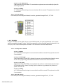
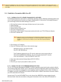
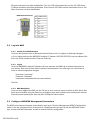
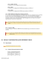
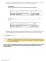
Installation Instructions
AMD8000-12-AC and AMD8000-12-DC
12-Port ADSL Mini DSLAMs With Both Full Rate and G.lite Operational Modes
220-0000050 rev04
© Copyright 2002 Net to Net Technologies, Inc.
™ The Net to Net Logo is a trademark of Net to Net Technologies, Inc.
Worldwide Headquarters
Net to Net Technologies
112 Corporate Drive, Suite 1
Portsmouth, NH 03801
USA
+1 877-638-2638
220-0000050 rev04
http://www.nettonet.com/
[email protected]
EMEA Headquarters
Net to Net Technologies
Victoria House 19 Park Way
Newbury Berkshire RG14 1EE
UK
+44 (0) 1635 570950
Contents
1.0 INSTALLATION
1.1 Unpack and Inspect the Equipment
1.2 Install an Uplink Interface Module (UIM)
1.3 Select the Installation Site
1.3.1 Tabletop
1.3.2 Rack
1.4 Power Up the AMD8000
1.4.1 AC Power
1.4.2 DC Power
1.5 Connect the ADSL Line
1.5.1 Default Configurations
1.5.1.1 Operational Mode
1.5.1.2 Bandwidth
1.5.2 ADSL RJ21 Pinout
1.6 Connect the Uplink Interface Line(s)
1.6.1 10/100 Ethernet Uplink
1.6.1.1 Configuration Defaults
1.6.1.2 Ethernet RJ45 Pinout
1.6.2 T1 Uplink
1.6.2.1 Configuration Defaults
1.6.2.2 T1 RJ45 Pinout
1.6.3 E1 Uplink
1.6.3.1 Configuration Defaults
1.6.3.2 E1 RJ45 Pinout
1.6.4 DS3 Uplink
1.6.4.1 Configuration Defaults
1.6.5 E3 Uplink
1.6.5.1 Configuration Defaults
2.0 INITIAL CONFIGURATION
2.1 Establish a Connection With Your PC
2.1.1 Configure Your PC to Enable Communication with NMS
2.1.2 Connect Your PC to the AMD8000 Management Port
2.2 Log into NMS
2.2.1 Launch Your Web Browser
2.2.2 Log In
2.2.3 NMS Navigation
2.3 Configure AMD8000 Management Parameters
2.3.1
2.3.2
2.3.3
2.3.4
2.3.5
IP Address, Subnet Mask and Gateway
Inband Management
Inband Management VLAN ID
Trivial File Transfer Protocol
Submit Changes
2.4 Reconnect with NMS
2.4.1
2.4.2
2.4.3
2.4.4
220-0000050 rev04
Reconfigure the IP Address and Subnet Mask on Your PC
Relaunch Your Web Browser
Log In
DSLAM Interconnection
2.4.4.1 Neither (default)
2.4.4.2 UIM 1
2.4.4.3 UIM 2
2.4.5 Make Additional Configuration Changes as Desired
2.4.6 Log Out of NMS
3.0 DEFAULT CONFIGURATION QUICK REFERENCE TABLES
3.1 User Access
3.1.1 Network Management System (NMS)
3.1.2 Simple Network Management Protocol (SNMP)
3.2 AMD8000 Management Parameters
3.3 ADSL Port Parameters
3.4 Uplink Interface Port Parameters
3.4.1
3.4.2
3.4.3
3.4.4
3.4.5
10/100 Ethernet Uplink
T1 Uplink
E1 Uplink
DS3 Uplink
E3 Uplink
4.0 ADSL PARAMETER DEFINITIONS AND CONFIGURATION OPTIONS
4.1 Operational Mode
4.1.1 Multimode (default)
4.1.2 Full Rate: G.DMT, T1.413 or Alcatel
4.1.3 G.lite
4.2 Port Mode
4.2.1 Adaptive (default)
4.2.2 On
4.2.3 Off
4.3 Bandwidth and Distance
4.3.1 Full Rate
4.3.2 G.lite
4.4 VPI/VCI Detect
4.4.1 On (default)
4.4.2 Off
4.5 Frame Type
4.5.1 1483LLC (default)
4.5.2 1483VCM
5.0 ADDITIONAL INFORMATION
5.1 Data Storage
5.1.1 Memory
5.1.1.1 Random Access Memory (RAM)
5.1.1.2 Non-Volatile Random Access Memory (NVRAM)
5.1.2 Local Files
5.1.2.1 Backup
5.1.2.2 Template
5.2 AMD8000 Reset
5.3 LED Indications
5.4 Regulatory Compliance for Class A Equipment
220-0000050 rev04
CAUTION Net to Net Technologies strongly recommends the use of proper electrostatic discharge (ESD) precautions when handling
this equipment.
1.0
INSTALLATION
1.1
Unpack and Inspect the Equipment
The following components should be included:
z
z
z
z
z
z
z
1 AMD8000
4 Rubber Bumpers
1 Power Cord (AC versions only)
2 Rack Mount Brackets
10 #6 Phillips Rack Mount Bracket Screws
4 #10 Phillips Rack Screws
4 #12 Phillips Rack Screws
If there is visible damage, do not attempt to connect the device. Contact Customer Support at 1-877-6382638 (1-603-427-0600 for international customers) or [email protected] .
1.2
Install an Uplink Interface Module (UIM)
A UIM provides the upstream network connection for Net to Net Technologies' Mini DSLAMs. An AMD8000
cannot function without a UIM. There are a variety of UIM models available for purchase, contact your Net to
Net sales representative for further information.
CAUTION Disconnect all power sources from the AMD8000 before installing an Uplink Interface Module.
z
z
z
Using a Phillips Screwdriver, remove the eight [8] screws securing the AMD8000 chassis and carefully
lift off the chassis cover. Set the screws aside.
Select a port for UIM installation; either port (1 or 2) may be used. Although not required for
operational purposes, if redundancy is desired, two UIMs may be installed, one in each port.
Remove the blanking plate from the selected port.
CAUTION Blanking plates should be stored for possible future use: if a UIM is removed from the
AMD8000, it must be replaced with either another UIM or a blanking plate. DO NOT
OPERATE AN AMD8000 WITH AN OPEN UIM PORT.
z
Carefully slide the faceplate of the UIM under the lip on the inside of the AMD8000 front panel, at the
selected port opening, such that the UIM circuit board is facedown and the label shows through the
port opening (from the outside) with the UIM model name along the right-hand edge.
220-0000050 rev04
z
z
z
z
z
1.3
Ensure that the mounting holes on the UIM circuit board are lined up with the corresponding pems on
the AMD8000 circuit board and that the board-to-board connector key pins are properly aligned.
Gently press down with even pressure on all four corners of the UIM until the board-to-board
connector is fully seated.
Secure the UIM circuit board to the AMD8000 circuit board, at the pems, with the four [4] provided
panhead screws.
Secure the UIM faceplate to the front panel of the AMD8000 using the two [2] provided beige
flathead screws.
Replace the chassis cover and secure with the original eight [8] beige flathead screws.
Select the Installation Site
CAUTION The maximum recommended ambient temperature for the AMD8000 is 65° Celsius (149° Fahrenheit).
1.3.1
Tabletop
Affix the (4) provided rubber bumpers to the bottom corners of the AMD8000, to provide surface grip,
and place the AMD8000 such that the cables will not become a tripping hazard or pull loose from the
chassis. Ensure that the air supply vents are not blocked.
1.3.2
Rack
Using a Phillips Screwdriver, attach the (2) provided rack mount brackets to the sides of the
AMD8000 with the (10) provided bracket screws. Mount the chassis onto the rack and secure the
rack mount brackets to the sides of the rack using one of the two provided sets of (4) rack mount
screws (whichever size fits the rack being utilized). Check the rack for stability, ensuring that
installation of the AMD8000 has not caused the rack to become top-heavy. Check that all cables are
secured such that they will not become a tripping hazard or pull loose from the AMD8000.
1.4
Power Up the AMD8000
1.4.1
AC Power
Plug the provided AC Power Supply Cord into the back of the AMD8000-12-AC and connect it to your
power source. Turn the power switch ON (ON="|", OFF="0") and verify that the Power (PWR) LED on
the front of the AMD8000 is illuminated.
1.4.2
DC Power
Attach your DC power leads and ground connection to one of the two terminal blocks on the back of
the AMD8000-12-DC. Either terminal block may be used or both may be used for redundancy
(backup). Be sure to attach the positive lead (+) to the positive terminal (+) and the negative lead (-) to
the negative terminal (-) as indicated on the terminal block labels. Turn your power source on and
verify that the Power (PWR) LED on the front panel of the AMD8000 is illuminated.
220-0000050 rev04
1.5
Connect the ADSL Line
Plug your ADSL cable RJ21 connector into the RJ21 port on the front of the AMD8000. For most
applications, an AMD8000 ADSL link requires a straight-through DSL cable. For each port being connected
to a remote ADSL modem, verify that the ADSL link has been established; the ADSL Lk (Link) LED for that
port will illuminate solid or flashing green to indicate the connection has been made. Link up time for
connections between the AMD8000 and remote ADSL modems can vary from one to five minutes
depending on the quality, gauge and distance of the copper cables.
1.5.1
Default Configurations
1.5.1.1
Operational Mode
The default AMD8000 operational mode is MULTIMODE: each port will detect, and match, the
operational mode of the remote ADSL modem to which it's connected.
1.5.1.2
Bandwidth
The default AMD8000 bandwidth is ADAPTIVE: each port will automatically train up to the best
possible speed supported by the AMD8000, the remote ADSL modem and the copper cable pair
connecting the two.
1.5.2
ADSL RJ21 Pinout
A voice and data splitter is built into Net to Net Technologies' AMD8000: pins 1-12 and 26-37 provide
the data link, pins 14-25 and 39-50 provide the voice link.
Port 1
ADSL
VOICE
Tip
2
3
4
5
6
7
8
9
10 11 12
26 27 28 29 30 31 32 33 34 35
36
37
10
11
12
39 40 41 42 43 44 45 46 47 48
49
50
Ring 14 15 16 17 18 19 20 21 22 23
24
25
Ring 1
Tip
2
3
4
5
6
7
8
9
Pins 13 and 38 are not used.
1.6
Connect the Uplink Interface Line(s)
Instructions for establishing a network connection with your AMD8000 depend upon the Uplink Interface
Module (UIM) model type(s) installed in your Mini DSLAM in Section 1.2.
1.6.1
10/100 Ethernet Uplink
Plug your Ethernet cable into the RJ45 10/100 Ethernet port on the UIM faceplate. For most
applications, an Ethernet UIM connects to a PC using a straight-through Ethernet cable and to a hub
or a switch using a crossover Ethernet cable. For any other connection combinations you must verify
the pinout of the Ethernet device to which you are connecting the UIM in order to determine which
type of cable is required. Verify the connection: solid green illumination of the Link (Lnk) LED on the
UIM faceplate indicates an Ethernet connection has been established. If the Lnk LED is illuminated
but not the 100 LED then a 10 Mbps connection has been established. If the Lnk and 100 LEDs are
both illuminated, then a 100 Mbps connection has been established.
220-0000050 rev04
1.6.1.1
Configuration Defaults
1.6.1.1.1
Duplex Mode
Auto-negotiate: a 10/100 Ethernet UIM will detect, and match, the duplex mode of the
remote device (PC, hub, switch, etc.) to which it's connected.
1.6.1.1.2
Speed
Auto-negotiate: a 10/100 Ethernet UIM will detect, and match, the speed of the remote
device (PC, hub, switch, etc.) to which it's connected.
NOTE For the best connection results, the remote device (PC, hub, switch, etc.) should also be set to auto-
negotiate duplex mode and speed. If the remote device cannot be configured to auto-negotiate, speed
may be hard set at either 10 Mbps or 100 Mbps but duplex mode MUST be hard set to Half Duplex; a
10/100 Ethernet connection cannot be made if the remote device is hard set to Full Duplex.
1.6.1.2
Ethernet RJ45 Pinout
PIN CONNECTION
1.6.2
1
Rx+
2
Rx-
3
Tx+
4
not used
5
not used
6
Tx-
7
not used
8
not used
T1 Uplink
Plug your T1 cable into the RJ45 T1 port on the UIM faceplate. For most applications, a T1 uplink
requires a straight-through T1 cable. Verify the connection: solid or flashing green illumination of the
Link (Lnk) LED on the UIM faceplate indicates a T1 connection has been established.
1.6.2.1
Configuration Defaults
1.6.2.1.1
Speed
A T1 UIM determines speed via communication with the remote T1 equipment to which it
is connected.
1.6.2.1.2
Frame Type
Extended Super Frame (ESF): data is assembled into 24-frame transmission clusters and
integrates both Facilities Data Link (FDL) and Cyclic Redundancy Check (CRC).
1.6.2.1.3
Line Code
Bipolar with 8 Zero Substitution (B8ZS): prevents loss of synchronization with remote
equipment by using bipolar violations to guarantee the presence of pulses in the T1 line.
220-0000050 rev04
1.6.2.1.4
Line Attenuation
0 dB: receivers on most newer T1 transmission equipment can automatically adjust for
incoming amplitude.
1.6.2.1.5
Timing
A T1 UIM determines timing via communication with the remote T1 equipment to which it
is connected.
1.6.2.2
T1 RJ45 Pinout
If the cable you are using is shielded, it must be grounded through Pins 3, 6, 7 & 8.
PIN CONNECTION
1.6.3
1
Rx Ring
2
Rx Tip
3
not used
4
Tx Ring
5
Tx Tip
6
not used
7
not used
8
not used
E1 Uplink
Plug your E1 cable into the RJ45 E1 port on the UIM faceplate. For most applications, an E1 uplink
requires a straight-through E1 cable. Verify the connection: solid or flashing green illumination of the
Link (Lnk) LED on the UIM faceplate indicates an E1 connection has been established.
1.6.3.1
Configuration Defaults
1.6.3.1.1
Speed
An E1 UIM determines speed via communication with the remote E1 equipment to which
it is connected.
1.6.3.1.2
Frame Type
Cyclic Redundancy Check (CRC): detects line errors and scrutinizes data integrity across
the E1 line by appending a hexidecimal checksum to the end of each E1 frame.
1.6.3.1.3
Line Code
High Density Binary 3 (HDB3): accommodates the minimum ones density requirement in
the European public network by using bipolar violations to guarantee the presence of
pulses in the E1 line.
1.6.3.1.4
Timing
An E1 UIM determines timing via communication with the remote E1 equipment to which
it is connected.
1.6.3.2
E1 RJ45 Pinout
If the cable you are using is shielded, it must be grounded through Pins 3, 6, 7 & 8.
220-0000050 rev04
PIN CONNECTION
1.6.4
1
Rx Ring
2
Rx Tip
3
not used
4
Tx Ring
5
Tx Tip
6
not used
7
not used
8
not used
DS3 Uplink
Plug your DS3 BNC cable connectors into the corresponding Rx and Tx BNC ports on the DS3 UIM
faceplate. Verify the connection: solid or flashing green illumination of the Link (Lnk) LED on the UIM
faceplate indicates a DS3 connection has been established.
1.6.4.1
Configuration Defaults
1.6.4.1.1
Clock Source
A DS3 UIM determines clock source via communication with the remote DS3 equipment
to which it is connected.
1.6.4.1.2
Tx Line Buildout
0-225 feet (0-69 meters).
1.6.5
E3 Uplink
Plug your E3 BNC cable connectors into the corresponding Rx and Tx BNC ports on the E3 UIM
faceplate. Verify the connection: solid or flashing green illumination of the Link (Lnk) LED on the UIM
faceplate indicates an E3 connection has been established.
1.6.5.1
Configuration Defaults
1.6.5.1.1
Clock Source
An E3 UIM determines clock source via communication with the remote E3 equipment to
which it is connected.
1.6.5.1.2
Tx Line Buildout
0-225 feet (0-69 meters).
2.0
INITIAL CONFIGURATION
Initial configuration of an AMD8000 must be completed via Net to Net Technologies' Network Management
System (NMS). You must have a web browser, such as Microsoft Internet Explorer or Netscape Navigator,
installed on your PC in order to access NMS. Refer to the NMS Management User Guide
(http://www.nettonet.com/support/docs/210-0000048) for a complete list of system requirements.
220-0000050 rev04
NOTE Although the AMD8000 can also be managed via Simple Network Management Protocol (SNMP), initial configuration of IP
Address, Subnet Mask and Gateway must first be completed via NMS before you will be able to access AMD8000 management
with SNMP.
2.1
Establish a Connection With Your PC
2.1.1
Configure Your PC to Enable Communication with NMS
The following instructions are based on a Windows operating system; different operating systems may
vary in their requirements. Contact your System Administrator or Information Technology Manager if
you are having trouble with these settings. On your PC:
z
z
z
z
z
z
z
Click the Start button in the lower left-hand corner of your monitor
Select Settings
Click Control Panels
Double-click the Network icon
Click the Configuration tab
Scroll down under Network Components and double-click your TCP/IP Ethernet Adapter
Click the IP Address tab
NOTE Make note of the current IP Address and Subnet Mask configurations on your PC
BEFORE entering Net to Net's defaults; once initial configuration of NMS has been
completed, you will need to reconfigure your PC with these original proprietary
values.
z
z
Click Specify an IP Address
Enter an IP Address within Net to Net's default range:
AMD8000 default: 192.168.254.252
Your PC: 192.168.254.xxx
The IP Address entered for your PC must be within the same range as Net to
Net's default AMD8000 IP Address, but cannot exactly duplicate it. As such,
xxx is user defined (1 - 254) but CANNOT equal 252.
z
z
z
2.1.2
Enter Net to Net's default Subnet Mask (255.255.255.0)
Click Add
Click OK (you may be prompted to reboot your PC)
Connect Your PC to the AMD8000 Management Port
The 10/100 Ethernet Management (MGMT) Port auto-negotiates speed and duplex mode by default.
For the best configuration results, your PC should be set to auto-negotiate speed and duplex mode as
well. If your PC cannot be configured to auto-negotiate, speed may be hard set at either 10 Mbps or
100 Mbps but duplex mode MUST be hard set to Half Duplex; a MGMT connection cannot be made if
your PC is hard set to Full Duplex.
Connect your PC to the RJ45 MGMT Port on the front of the AMD8000 using a straight-through
Ethernet cable. Verify the connection; solid green illumination of the Link (Lnk) LED indicates an
220-0000050 rev04
Ethernet connection has been established. If the Lnk LED is illuminated but not the 100 LED then a
10 Mbps connection has been established. If the Lnk and 100 LEDs are both illuminated, then a 100
Mbps connetion has been established.
MGMT RJ45 Port Pinout
2.2
PIN CONNECTION
1
Rx+
2
Rx-
3
Tx+
4
not used
5
not used
6
Tx-
7
not used
8
not used
Log into NMS
2.2.1
Launch Your Web Browser
Launch a web browser such as Microsoft Internet Explorer (v4.0 or higher) or Netscape Navigator
(v4.0 or higher) and type the AMD8000's default IP Address (192.168.254.252) into the address field
at the top of the browser window. Press the Enter key.
2.2.2
Log In
Once the AMD8000's default IP Address has been entered, the NMS Log In window will appear on
your screen. Enter Net to Net's default username and password. You must log in as a Superuser in
order to make configuration changes.
Username: "superuser"
Password: "Password"
(usernames and passwords are case sensitive)
Click OK.
2.2.3
NMS Navigation
Once you have logged into NMS, use the Tab key or your mouse to move from field to field. Net to Net
does not recommend using the Enter key to navigate; some web browsers (such as Microsoft Internet
Explorer) equate pressing the Enter key with clicking the Submit button.
2.3
Configure AMD8000 Management Parameters
The NMS main window will appear automatically upon log in. Click the Management (MGMT) Configuration
button in the top, left-hand corner of the window. A floating window will pop up with the AMD8000 model
type, revision and MAC Addresses, as well as several fields for configuration.
220-0000050 rev04
CAUTION It is recommended that you set ALL applicable fields in the MGMT Configuration window before clicking the Submit
button; each time the Submit button is clicked you will be required to re-establish NMS connectivity.
2.3.1
IP Address, Subnet Mask and Gateway
Enter your proprietary IP Address, Subnet Mask and Gateway configurations in the appropriate fields.
The AMD8000 Subnet Mask and Gateway configurations must match the proprietary configurations
that were on your PC prior to Net to Net's defaults being entered (Section 2.1.1). The IP Address
entered should be in the same proprietary range as that which was on your PC but cannot duplicate it
exactly. Contact your System Administrator or Information Technology Manager if you do not know the
values necessary to properly configure these fields.
2.3.2
Inband Management
If remote network utilization of NMS or SNMP is desired, click the Inband MGMT box so that a
checkmark appears.
CAUTION Managing the AMD8000 via an inband connection can increase the security risks of unapproved and/or
unwanted users accessing the management system. It is recommended that inband management be
disabled when not in use.
2.3.3
Inband Management VLAN ID
If your network is running VLANs to facilitate packet direction and/or promote packet security, enter
an Inband MGMT (Management) VLAN ID in the appropriate field. If your network is not running
VLANs, leave the Inband MGMT VLAN ID field blank.
2.3.4
Trivial File Transfer Protocol
Both system and port configurations can be saved on your PC or local network as a backup, and/or
for use as a template for future configurations, via a Trivial File Transfer Protocol (TFTP) tool. Click On
to enable or Off to disable this feature. Refer to Section 5.1.2 for specific instructions regarding the
creation of local files.
2.3.5
Submit Changes
Click the Submit button and exit your web browser.
NOTE NMS connectivity will be lost immediately upon clicking the Submit button; you must close your web browser,
reconfigure the IP Address and Subnet Mask on your PC and then re-launch your web browser. Refer to Section
2.4.
2.4
Reconnect with NMS
2.4.1
Reconfigure the IP Address and Subnet Mask on Your PC
The following instructions are based on a Windows operating system; different operating systems may
vary in their requirements. Contact your System Administrator or Information Technology Manager if
you are having trouble with these settings. On your PC:
220-0000050 rev04
z
z
z
z
z
z
z
z
Click the Start button in the lower left-hand corner of your monitor
Select Settings
Click Control Panels
Double-click the Network icon
Click the Configuration tab
Scroll down under Network Components and double-click your TCP/IP Ethernet Adapter
Click the IP Address tab
Depending upon which option was selected PRIOR to entering Net toNet's default IP Address
and Subnet Mask (in Section 2.1.1), do one of the following:
Click Obtain an IP Address Automatically
OR
Click Specify an IP Address and then manually enter your proprietary IP
Address and Subnet Mask
NOTE The Subnet Mask entered on your PC must match the proprietary configurations set
on the AMD8000 in Section 2.3.1. The IP Address entered must be in the same
proprietary range that was set on the AMD8000 but cannot duplicate it exactly.
Contact your System Administrator or Information Technology Manager if you do not
know the values necessary to properly configure these fields.
z
2.4.2
Click OK (you may be prompted to reboot your PC)
Relaunch Your Web Browser
Launch your web browser and type the AMD8000's new IP Address (as defined in Section 2.3.1) in
the address field at the top of the browser window. Press the Enter key.
2.4.3
Log In
Enter Net to Net's default username and password. You must log in as a Superuser in order to make
configuration changes.
Username: "superuser"
Password: "Password"
(usernames and passwords are case sensitive)
Click OK.
2.4.4
DSLAM Interconnection
The AMD8000 may be interconnected (daisy-chained) with additional Net to Net Mini, Micro or IP
DSLAMs such that a single router may be used for all. The uplink port at one end (ONLY one), of each
connection between two DSLAMs, must be configured to utilize the DSLAM Interconnection function.
Click one of the two UIM ports (either one) pictured on the AMD8000 in the NMS main window . The
DSLAM Interconnection Configuration window will pop up with the Mini DSLAM model type and
revision number. Click the desired interconnection configuration in the pull-down menu and then click
the submit button.
220-0000050 rev04
2.4.4.1
Neither (default)
The AMD8000 is not configured for interconnection.
2.4.4.2
UIM 1
The AMD8000 is configured for DSLAM interconnection via UIM Port 1.
2.4.4.3
UIM 2
The AMD8000 is configured for DSLAM interconnection via UIM Port 2.
2.4.5
Make Additional Configuration Changes as Desired
You may now make desired configurations with NMS through either the established direct connection
or, if you chose to set Inband Management in Section 2.3.2, via a remote network connection.
Likewise, if you chose to set Inband Management, you will now also be able to utilize SNMP across
the network. Refer to Net to Net's NMS and/or SNMP Management User Guides for information
regarding specific parameter configurations.
NOTE Net to Net Technologies recommends changing default passwords immediately following initial setup to help
ensure that any subsequent configurations of the management system will not be inadvertently altered or
deleted.
2.4.6
Log Out of NMS
If you do not log out of NMS, the AMD8000 will automatically log you out after five minutes of
inactivity.
CAUTION If you leave your workstation without logging out and another user accesses NMS before the five minute
inactivity period has expired, the new user will have full access to the management system without being
required to log in.
3.0
DEFAULT CONFIGURATION QUICK REFERENCE TABLES
3.1
User Access
NOTE All usernames and passwords are case sensitive.
3.1.1
Network Management System (NMS)
ACCESS
USERNAME
PASSWORD
read/write
superuser
Password
read only
general
Password
220-0000050 rev04
3.1.2
3.2
3.3
Simple Network Management Protocol (SNMP)
ACCESS
COMMUNITY STRING
read/write
Password
read only
Password
AMD8000 Management Parameters
PARAMETER
DEFAULT CONFIGURATION
Gateway
0.0.0.0
Inband Management
off
Inband Management VLAN ID
0 (off)
IP (Internet Protocol) Address
192.168.254.252
Subnet Mask
255.255.255.0
TFTP (Trivial File Transfer Protocol)
enabled
Uplink DSLAM Interconnection
neither (off)
ADSL Port Parameters
PARAMETER
DEFAULT CONFIGURATION
Circuit Identification
n/a (no default)
Back-bone VLAN
0 (off)
Flood
uplink
Frame Type
1483LLC
IP Range 1
0.0.0.0 - 255.255.255.255 (all)
IP Range 2
0.0.0.0 - 0.0.0.0
Operational Mode
Multimode
Priority (VLAN)
0 (none)
Protocol
all
Speed Downstream
n/a (Adaptive Port Mode)
Speed Upstream
n/a (Adaptive Port Mode)
VLAN Range
0 - 0 (off)
VCI (Virtual Channel Identifier)
0
VPI (Virtual Path Identifier)
35
VPI/VCI Detect
on
220-0000050 rev04
3.4
Uplink Interface Port Parameters
3.4.1
3.4.2
3.4.3
3.4.4
3.4.5
10/100 Ethernet Uplink
PARAMETER
DEFAULT
Speed
Auto-Negotiate
Duplex Mode
Auto-Negotiate
T1 Uplink
PARAMETER
DEFAULT
Frame Type
ESF (Extended Super Frame)
Line Attenuation
0 dB
Line Code
B8ZS (Bipolar with 8 Zero Substitution)
Speed
Auto-Negotiate
Timing
Auto-Negotiate
E1 Uplink
PARAMETER
DEFAULT
Frame Type
CRC (Cyclic Redundancy Check)
Line Code
HDB3 (High Density Bipolar 3)
Speed
Auto-Negotiate
Timing
Auto-Negotiate
DS3 Uplink
PARAMETER
DEFAULT
Clock Source
local
Line Buildout
0-225 feet (0-69 meters)
E3 Uplink
PARAMETER
DEFAULT
Clock Source
local
Line Buildout
0-225 feet (0-69 meters)
220-0000050 rev04
4.0
ADSL PARAMETER DEFINITIONS AND CONFIGURATION OPTIONS
NOTE Parameters common to all Mini DSLAM models are defined in the NMS and SNMP Management User Guides. ADSL
configurations, however, are specific to AMD8000s and are defined here.
4.1
Operational Mode
4.1.1
Multimode (default)
The ADSL port will detect and match the operational mode of the remote ADSL modem to which it's
connected.
4.1.2
Full Rate: G.DMT, T1.413 or Alcatel
Installation of an in-line splitter is required at both ends of the ADSL connection when a single line is
used for both phone and data.
4.1.3
G.lite
Installation of an in-line splitter is required at the AMD8000 end of the connection, and microfilters
are required at the remote end of the connection, when a single line is used for both phone and data.
4.2
Port Mode
4.2.1
Adaptive (default)
The ADSL port will automatically train up to the best possible speed supported by the AMD8000, the
remote ADSL modem and the copper cable pair connecting the two.
4.2.2
On
The ADSL port will require upstream and downstream bandwidths to be specified individually.
4.2.3
Off
The ADSL port has been administratively turned off.
4.3
Bandwidth and Distance
The default ADSL bandwidth setting is adaptive, allowing each port to train up to the best possible speed
circumstances will allow. The eventual outcome could be any combination of existing possible upstream
and downstream bandwidths and may, or may not, be reflected in the following tables. When port mode is
set to On, upstream and downstream bandwidths must be selected manually for that port. See Net to Net's
NMS and/or SNMP Management User Guides for further instruction.
Distance capabilities listed below assume the use of 26 American Wire Gauge (AWG) cable; connections
made with cable of a greater gauge (e.g., 24 AWG) will link up at greater distances. The AMD8000 may not
link up if the cable is in poor condition or if the cable distance is greater than a particular bandwidth will
support. Remote ADSL modems determine bandwidth through their communication with the AMD8000.
220-0000050 rev04
NOTE The following tables show maximum possible distances for various sample combinations of upstream and
downstream bandwidths over a typical ADSL line. Data given is meant solely as a guide in determining
achievable distances at various bandwidth settings; these tables are NOT COMPREHENSIVE. The many
possible combinations of upstream and downstream bandwidths, along with attainable corresponding distances for each
combination, are far more numerous than that which is feasible to list here.
4.3.1
Full Rate
T1.413, Alcatel and G.DMT
UP
DWN*
DIST
kbps
1,024 1,024 1,024
960
896
832
736
576
416
384
288
192
96
8,064 7,712 7,072
5,632
4,480
3,584
2,784
2,144
1,696
1,184
832
512
288
ft
8,000 9,000 10,000 11,000 12,000 13,000 14,000 15,000 16,000 17,000 18,000 19,000 20,000
m
2,438 2,743 3,048
3,353
3,658
3,962
4,267
4,572
4,877
5,182
5,486
5,791
6,096
*Under optimal circumstances, the AMD8000 is capable of reaching downstream speeds of up to 10,512 kbps.
4.3.2
G.lite
UPSTREAM
DOWNSTREAM
DISTANCE
kbps
feet
512
416
288
192
128
1,536
1,536
1,056
768
448
15,000 16,000 17,000 18,000 19,000
meters 4,572
4,877
5,182
5,486
5,791
Net to Net Technologies' ADSL Micro DSLAMs exceed the International Telecommunications Union Telecommunications Standardization Sector (ITU-T) Recommendation G992.1 minimum speed
requirements of 640 kbps upstream and 6,000 kbps downstream.
4.4
VPI/VCI Detect
ADSL data travels by way of Asynchronous Transfer Mode (ATM) Cells across Permanent Virtual Circuits
(PVCs). Each PVC consists of one Virtual Channel across one Virtual Path. The AMD8000 supports one PVC
per port.
z
z
4.4.1
Virtual Path Identifier (VPI): an 8-bit field in ATM cell headers that routes a cell over the
correct Virtual Path
Virtual Channel Identifier (VCI): a 16-bit field in ATM cell headers that routes a cell to the
proper Virtual Channel once it is on the correct Virtual Path
On (default)
The ADSL port will automatically "snoop" the line to determine the VPI/VCI setting of the remote ADSL
modem to which it's connected and set itself accordingly. If no ATM cells are detected (at any VPI/VCI
setting), the port will default to VPI 0 and VCI 35. Once it does detect ATM cells from the remote ADSL
modem, it will then reconfigure the VPI/VCI with the same settings at which the ATM cells were
detected.
220-0000050 rev04
4.4.2
Off
The ADSL port will default to VPI 0 and VCI 35 UNLESS the port was previously set to VPI/VCI Detect
On and had already detected the VPI/VCI of the remote ADSL modem. In this case, turning the VPI/VCI
Detect function Off will lock in the previously detected settings until, or unless, VPI/VCI values are
altered manually. Each port must be assigned the same VPI/VCI as the remote ADSL modem to which
it's connected in order for the units to communicate.
NOTE An ADSL port's VPI/VCI Detect function should be set to OFF before manual configuration of VPI and VCI values.
4.5
Frame Type
Frame type is the ADSL data encapsulation method for carrying traffic over an ATM network as defined by
the Internet Engineering Task Force (IETF) Request for Comment 1483 (RFC1483).
4.5.1
1483LLC (default)
Logic Link Control (LLC) encapsulation multiplexes multiple protocols over a single ATM Virtual Circuit
whereby 1483LLC is the protocol-identifying frame header.
4.5.2
1483VCM
Virtual Circuit Multiplexing (VCM) creates a separate ATM Virtual Circuit connection for each protocol
type without additional encapsulation.
5.0
ADDITIONAL INFORMATION
5.1
Data Storage
Default parameters will remain in place unless changed through NMS or SNMP.
5.1.1
Memory
Configuration backup is inherent in Net to Net Technologies' Mini DSLAMs. AMD8000 parameter
configurations are automatically recorded in both Random Access Memory (RAM) and Non-Volatile
Random Access Memory (NVRAM).
5.1.1.1
Random Access Memory (RAM)
Data stored in RAM will be erased if the AMD8000 loses power.
5.1.1.2
Non-Volatile Random Access Memory (NVRAM)
Data stored in NVRAM will remain intact (even if the AMD8000 loses power) unless deliberately
cleared or reconfigured.
5.1.2
Local Files
Both management and port configurations can be saved on your PC or local network as a backup
and/or for use as a template for future configurations. Once the AMD8000 has been configured as
220-0000050 rev04
desired, the settings can be flash uploaded (from the AMD8000 to a local file) through a Trivial File
Transfer Protocol (TFTP) tool with a GET command and the following information:
5.1.2.1
Backup
An AMD8000 backup file records ALL management and port configurations.
ITEM
Host Name
DATA NEEDED FOR BACKUP
Mini DSLAM IP Address: xxx.xxx.xxx.xxx
EXAMPLE
193.166.254.98
Remote Filename NVR_BACKUP.BIN.[superuser password]
nvr_backup.bin.Password
Local Filename
amd8000_22_backup.bin
5.1.2.2
user preference
Template
An AMD8000 template file records all management and port configurations EXCEPT IP
ADDRESS.
ITEM
Host Name
DATA NEEDED FOR BACKUP
EXAMPLE
Mini DSLAM IP Address: xxx.xxx.xxx.xxx 193.166.254.98
Remote Filename NVR_CFG.BIN.[superuser password]
nvr_cfg.bin.Password
Local Filename
n2n_amd8000_template.bin
user preference
Configuration files can also be flash downloaded FROM a local file TO an AMD8000, simply replace
the GET command with a PUT command. Refer to your TFTP user manual for further instruction.
5.2
AMD8000 Reset
CAUTION Resetting your AMD8000 will clear both RAM and NVRAM, restoring all of the original default settings
including Net to Net's original default IP Address, Subnet Mask and Gateway. Additionally, Inband Management will
revert to its original default setting (Off) and you will be required to establish a direct connection with the AMD8000
for any subsequent configurations.
Using a paperclip, mechanical pencil or similar tool, press and hold the Reset Button on the front, left-hand
side of the AMD8000 for 10 seconds (the button is not labeled). It will take approximately thirty [30]
seconds to complete.
220-0000050 rev04
5.3
LED Indications
LED
State
Indication
Additional Information
Power (PWR)
solid green
AMD8000 is receiving
power
If the AMD8000 is not receiving power,
none of the LEDs will be illuminated.
Fan
no
illumination
all chassis fans are
fully functional
solid amber
one or more fans have At least one of the four chassis fans is no
become non-functional longer working.
solid green
10 Mbps Ethernet
management
connection is
established
Applies only to direct connections from
the MGMT port to network equipment or
a PC; does not apply to inband
management access.
no
illumination
no direct Ethernet
management
connection
Applies only to direct connections from
the MGMT port to network equipment or
a PC; does not apply to inband
management access.
flashing
green
ADSL connection is
established and active
The port has received valid data from the
remote ADSL modem within the last
second.
solid green
ADSL connection is
established
An ADSL link exists and the port may be
transmitting but it has not received any
data from the remote ADSL modem
within the last second.
no
illumination
no ADSL connection
pulsing
amber
ADSL activity
The AMD8000 is receiving data from the
remote ADSL modem.
solid amber
heavy Rx traffic
The AMD8000 is receiving large amounts
of data from the remote ADSL modem.
no
illumination
no activity
A link may exist but the AMD8000 is not
receiving any data from the remote
ADSL modem.
pulsing
amber
ADSL activity
The AMD8000 is transmitting data to the
remote ADSL modem.
solid amber
heavy Tx traffic
The AMD8000 is transmitting large
amounts of data to the remote ADSL
modem.
no
illumination
no activity
A link may exist but the AMD8000 is not
transmitting any data to the remote
ADSL modem.
solid green
ETHERNET uplink is
established and active
The Activity (Act) LED will flash amber to
indicate traffic is flowing across the
Ethernet uplink.
flashing
green
T1/E1 or DS3/E3
uplink is established
and active
no
illumination
no uplink connection
Management Link (MGMT LNK)
ADSL Link (LK)
ADSL Data Reception (RX)
ADSL Data Transmission (TX)
UIM Link (LNK)
Note: Uplink LED indications depend upon the
UIM model type installed in your Mini DSLAM.
Refer to the your UIM Installation Instructions
for further information.
(A pulsing LED blinks steadily at a rate of once per second. A flashing LED blinks at a more rapid, less
constant rate.)
220-0000050 rev04
5.4
Regulatory Compliance for Class A Equipment
5.4.1
US Federal Communications Commission (FCC)
Note: This equipment has been tested and found to comply with the limits for a Class A digital device,
pursuant to part 15 of the FCC Rules. These limits are designed to provide reasonable protection
against harmful interference when the equipment is operated in a commercial environment. This
equipment generates, uses and can radiate radio frequency energy and, if not installed and used in
accordance with the instruction manual, may cause harmful interference to radio communications.
Operation of this equipment in a residential area is likely to cause harmful interference in which case
the user will be required to correct the interference at his own expense.
Caution: Changes or modifications not expressly approved by the manufacturer could void the user’s
authority to operate the equipment.
5.4.2
Industry Canada
This Class A digital apparatus complies with Canadian ICES-003.
Cet appareil numérique de la Classe A est conforme à la norme NMB-003 du Canada.
5.4.3
Europe
This Class A product complies with European Norm EN55022.
Warning: In a domestic environment this product may cause radio interference in which case the user
may be required to take adequate measures to correct the situation.
220-0000050 rev04
© Copyright 2002 Net to Net Technologies, Inc.
™ The Net to Net Logo is a trademark of Net to Net Technologies, Inc.
Worldwide Headquarters
Net to Net Technologies
112 Corporate Drive
Portsmouth, NH 03801
USA
+1 877-638-2638
220-0000050 rev04
http://www.NetToNet.com/
[email protected]
EMEA Headquarters
Net to Net Technologies
Victoria House 19 Park Way
Newbury Berkshire RG14 1EE
UK
+44 (0) 1635 570950