1
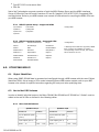
NMS Management User Guide
Network Management System v2.0
with
Simple Network Management Protocol v1.0
Portions of the IETF RFC1213 MIB-II
Systems Group and Interfaces Group
For Net to Net Technologies' Micro DSLAMs, Mini DSLAMs and IP DSLAMs:
210-0000048 rev06
© Copyright 2004 Net to Net Technologies, Inc.
™ The Net to Net Logo is a trademark of Net to Net Technologies, Inc.
Worldwide Headquarters
Net to Net Technologies
112 Corporate Drive, Suite 1
Portsmouth, NH 03801
USA
+1 877-638-2638
210-0000048 rev 06
http://www.nettonet.com/
[email protected]
EMEA Headquarters
Net to Net Technologies
Victoria House 19 Park Way
Newbury Berkshire RG14 1EE
UK
+44 (0) 1635 570950
Contents
1.0 OVERVIEW
1.1 System Requirements
1.1.1
1.1.2
1.1.3
1.1.4
Straight-through RJ45 to RJ45 Ethernet Cable
Web Browser
MIB Browser
Screen Resolution
1.2 Multi-User Support
1.3 Default Settings
1.3.1
1.3.2
1.3.3
1.3.4
1.3.5
User Access Defaults
System Defaults
Uplink Interface Defaults
Circuit Defaults
SNMP Trap Defaults
1.4 Data Storage
1.4.1 Random Access Memory (RAM) and Non-Volatile Random Access Memory (NVRAM)
1.4.2 Local Files
1.5 Data Management
1.5.1 IP DSLAM Data Management
1.5.1.1 Replacing an Interface Module
1.5.1.2 Replacing a Multiplexer Uplink Module (MUM)
1.5.2 Clearing NVRAM
1.5.2.1 IP DSLAM
1.5.2.2 Mini DSLAM
1.5.2.3 Micro DSLAM
2.0 NMS SETUP
2.1 Establish a Connection With the Micro DSLAM, Mini DSLAM or MUM
2.1.1 Configure Your PC to Enable Communication with NMS
2.1.2 Connect your PC to the MGMT Port (Port 1)
2.1.3 Launch a Web Browser and Log In
2.2 System Configuration
2.2.1
2.2.2
2.2.3
2.2.4
2.2.5
2.2.6
Set IP Address, Subnet Mask and Gateway
Set Inband Management
Set a Management IP Address Range (Micro DSLAMs ONLY)
Set TFTP Enable
Set Inband MGMT VLAN ID (if applicable)
Submit Changes
2.3 Reconnect with NMS
2.3.1
2.3.2
2.3.3
2.3.4
2.3.5
Reconfigure IP Address and Subnet Mask on Your PC With The Original Values
Relaunch Your Web Browser and Enter the New IP Address
Make Additional Configuration Changes as Desired
Save Port Configurations to a Local File
Log Out of NMS
3.0 NMS NAVIGATION
3.1 NMS Main Window
3.1.1 Micro DSLAM Chassis Front View
3.1.1.1
3.1.1.2
3.1.1.3
3.1.1.4
3.1.1.5
210-0000048 rev 06
Power LED
Management Port and Corresponding LED
Uplink Ports and Corresponding LEDs
System Reset Button
Communication Port
3.1.1.6 SDSL Connection LEDs
3.1.1.7 View Circuit Summary Button
3.1.2 Mini DSLAM Chassis Front View
3.1.2.1
3.1.2.2
3.1.2.3
3.1.2.4
3.1.2.5
3.1.2.6
Power LED
Fan LED
Management Port
Uplink Interface Modules and Corresponding LEDs
SDSL RJ21 Cable Connector and Corresponding Port LEDs
View Circuit Summary Button
3.1.3 IP DSLAM Chassis Front View
3.1.3.1
3.1.3.2
3.1.3.3
3.1.3.4
Multiplexer Uplink Module(s) and Corresponding LEDs
Uplink Interface Modules and Corresponding LEDs
Interface Modules and Corresponding LEDs
View Circuit Summary Buttons
3.1.4 Administration Panel
3.1.4.1
3.1.4.2
3.1.4.3
3.1.4.4
3.1.4.5
3.1.4.6
3.1.4.7
3.1.4.8
System Configuration Button
Global SNMP Trap Settings Button
HTTP Password Administration Button
Online Help Button
Chassis View Refresh Button
Circuit Search Field
Notes Field
Submit Button
3.2 Circuit Information and Configuration Window
3.2.1
3.2.2
3.2.3
3.2.4
3.2.5
3.2.6
3.2.7
3.2.8
Model Information
Slot and Port Selectors
Circuit ID
IP Range 1
IP Range 2
Speed
Protocol
VLAN Range
3.2.8.1 VLAN 0 / OFF (Default)
3.2.8.2 Single VLAN / Access Port
3.2.8.3 VLAN Range / Trunk Port
3.2.9 Backbone-VLAN
3.2.10 Pri (Priority)
3.2.11 Flood
3.2.11.1 Upl (Uplink - Default)
3.2.11.2 Vln (VLAN)
3.2.12
3.2.13
3.2.14
3.2.15
3.2.16
Submit
Statistical Information
Port Status
CPE ID (Loop Bonding Products ONLY*)
Loop Bonded Group (Loop Bonding Products ONLY*)
3.3 Circuit Summary Window
3.3.1 Port Data
3.3.2 Slot Selector (IP DSLAMs ONLY)
3.4 DSLAM Interconnect Configuration Window (IP DSLAMs Only)
3.5 Global SNMP Trap Settings Window
3.5.1 SNMP Trap Notification IP
3.5.2 Authentication Trap
3.5.3 Environment Trap
3.5.3.1 Fan Trap (Mini DSLAMs and IP DSLAMs ONLY)
3.5.3.2 Temperature Exceeded Trap (Micro DSLAMs ONLY)
3.5.3.3 Temperature Normal Trap (Micro DSLAMs ONLY)
3.5.4 Cold Start Trap
3.5.5 Module/Port Trap
3.5.5.1 Link Up/Down Trap
3.5.5.2 Module Removed Trap (IP DSLAMs ONLY)
3.5.5.3 Module Present Trap (IP DSLAMs ONLY)
3.5.6 Submit Button
3.5.7 SNMP Community Administration Window
3.6 Management Port Status Window (Micro DSLAMs ONLY)
210-0000048 rev 06
3.7 Uplink Interface Configuration Window (Micro DSLAMs ONLY)
3.7.1 10/100 Ethernet Uplink Configuration Window
3.7.2 T1 Uplink Configuration Window
3.7.3 E1 Uplink Configuration Window
4.0 TROUBLESHOOTING NMS
4.1 PC Can't Locate Web Server
4.2 Lost Web Server Connection
4.3 Cannot Establish a Web Server Connection From Within the Network
4.4 Web Pages are Loading Slowly
4.4.1 Too Many Users
4.4.2 Inband Connection Speed Not Set Appropriately
4.4.3 Network Congestion
5.0 MIB-II SETUP
5.1 Establish a Connection Between Your PC and the DSLAM
5.1.1 Network Connection
5.1.2 Direct Connection
5.2 Launch Your MIB Browser
5.3 Download the Supported MIB-II OIDs
5.3.1 MIB-II System Group - Supported OIDs
5.3.2 MIB-II Interfaces Group - Supported OIDs
6.0 UTILIZING MIB-II
6.1 Object Identifiers
6.2 Net to Net OID Indexes
6.2.1 Micro DSLAM Indexes
6.2.2 Mini DSLAM Indexes
6.2.3 IP DSLAM Indexes
6.2.3.1 IPD12000
6.2.3.2 IPD4000
6.3 MIB-II Commands
6.3.1 GET
6.3.2 GET NEXT
6.3.3 SET
7.0 TROUBLESHOOTING SNMP
7.1 System is Not Responding
7.1.1 Incorrect IP Address
7.1.2 Incorrect Community String
7.2 No Such Name SNMP Error Message
7.2.1 Incorrect Community String
7.2.2 Unsupported Object Indentifier (OID)
8.0 TECHNICAL SUPPORT
210-0000048 rev 06
1.0
OVERVIEW
Net to Net Technologies' Network Management System (NMS v2.0) allows DSLAM users access to statistical and
configuration data through a web server residing within the firmware of select Micro DSLAMs, Mini DSLAMs and
Multiplexer Uplink Modules (MUMs) in IP DSLAMs. Also incorporated are portions of the Systems Group and
Interfaces Group of Object Identifiers (OIDs) from the Internet Engineering Task Force (IETF) standardized
Management Information Base (MIB-II). MIB-II is part of the IETF Request for Comment 1213 (RFC1213) and
complies with Simple Network Management Protocol (SNMP). SNMP is the standard for management of
Transmission Control Protocol and Internet Protocol (TCP/IP) networks and network devices, such as Ethernet
bridges and routers.
1.1
System Requirements
1.1.1
Straight-through RJ45 to RJ45 Ethernet Cable
Required for establishing a direct connection from the Micro DSLAM, Mini DSLAM or IP DSLAM
MGMT (Management) Port to your PC for initial configuration.
1.1.2
Web Browser
Required for running NMS. Compatible web browsers include, but are not limited to, Microsoft
Internet Explorer (v4.0 or higher) and Netscape Navigator (v4.0 or higher). NMS is optimized for use
with Explorer.
Net to Net Technologies recommends that you use your browser's default settings when running
NMS. If JavaScript has been disabled for any reason, it must be enabled in order for you to utilize
NMS. If you are unsure of your browser settings and/or do not know if JavaScript is enabled, contact
your System Administrator or Information Technology Manager for further assistance.
1.1.3
MIB Browser
Required for MIB configuration. Any standard MIB Browser currently on the market will serve the
purpose; there are no specific program requirements.
1.1.4
Screen Resolution
1024 x 768 pixels is the minimum resolution required for all NMS views to fit within the dimensions
of most monitors and laptops. Monitor screen resolutions set at fewer pixels (e.g., 800 x 600 pixels)
may have issues with various NMS views lapsing beyond the width or height of the screen. To verify
and/or change screen resolution:
z
z
z
z
1.2
Right click on your desktop
Select Properties
Click the Settings tab
Adjust the Screen Resolution as needed
Multi-User Support
There are two classes of NMS Users: General and Super. General Users have read-only access and cannot
make any changes. Super Users have full access to make changes and update configurations. NMS
supports up to three Super OR three General Users simultaneously. Both classes of Users cannot log in at
the same time; attempts at such will result in a "Server Busy..." warning message.
210-0000048 rev 06
1.3
Default Settings
No configuration is necessary for a Micro DSLAM, Mini DSLAM or IP DSLAM to operate at default settings.
1.3.1
User Access Defaults
Username/Password
Community String
ACCESS
USERNAME*
PASSWORD*
ACCESS
COMMUNITY STRING*
read/write
superuser
Password
read/write
Password
read only
general
Password
read only
Password
*Usernames and passwords are case sensitive.
1.3.2
*Community strings are case sensitive.
System Defaults
IP Address
1.3.3
MODEL
DEFAULT IP
Micro
DSLAM
192.168.254.252
Mini DSLAM
192.168.254.252
IPD4000
Slot 5
System Parameters
PARAMETER
DEFAULT
Subnet Mask
255.255.255.0
Gateway
0.0.0.0
Inband Management
disabled
192.168.254.252
Mgmt (Management) IP Address
Filter Range
0.0.0.0 - 255.255.255.255
(all)
IPD12000
Slot 13
192.168.254.252
TFTP (Trivial File Transfer Protocol)
on
IPD12000
Slot 14
192.168.254.253
Inband Management VLAN ID
0 (off)
Uplink DSLAM Interconnection
1 (neither/off)
Uplink Interface Defaults
10/100 Ethernet Uplink
PARAMETER
(non-configurable)
Speed
Auto-Negotiate
Duplex Mode
Auto-Negotiate
T1 Uplink
PARAMETER
DEFAULT
Frame Type
ESF (Extended Super Frame)
Line Code
B8ZS (Bipolar with 8 Zero
Substitution)
Line
Buildout
0 dB
210-0000048 rev 06
E1 Uplink
PARAMETER
DEFAULT
Frame Type
CRC (Cyclic Redundancy
Check)
Line Code
HDB3 (High Density Bipolar 3)
1.3.4
Circuit Defaults
Circuit defaults common to all of Net to Net's DSLAMs are listed below. For information regarding
model specific circuit parameters, refer to the Interface Module User Guide or Micro DSLAM or Mini
DSLAM Installation Instructions specific to the model you are installing.
1.3.5
1.4
PARAMETER
DEFAULT
PARAMETER
DEFAULT
Circ. ID (Circuit Identification)
n/a (no default)
VLAN Range
0-0 (off)
IP Range 1
0.0.0.0 - 255.255.255.255
Backbone-VLAN
0 (off)
IP Range 2
0.0.0.0 - 0.0.0.0
Pri (VLAN Priority)
0 (none)
Protocol
All (all traffic)
Flood
Upl (Uplink)
SNMP Trap Defaults
NOTIFICATION IP
DEFAULT
TRAP
DEFAULT
IP Address 1
0.0.0.0
Authentication Trap
enabled
IP Address 2
0.0.0.0
Environment Trap
enabled
IP Address 3
0.0.0.0
Cold Start Trap
disabled
IP Address 4
0.0.0.0
Module/Port Trap
disabled
Data Storage
1.4.1
Random Access Memory (RAM) and Non-Volatile Random Access Memory (NVRAM)
Configuration backup is inherent in Net to Net Technologies' Micro DSLAMs, Mini DSLAMs and IP
DSLAMs. Upon intial power up, default parameters will remain in place unless changed through NMS
or SNMP. Once changed, new configurations will automatically be recorded in both RAM and
NVRAM. Although data stored in RAM will be erased if the DSLAM loses power, data stored within
NVRAM will remain intact (even if the unit loses power) unless deliberately cleared or reconfigured.
1.4.2
Local Files
Individual port configurations can be saved locally on your PC as a backup and/or for use as a
template for future configurations. Once a DSLAM has been configured as desired, the settings can
be flash uploaded through a Trivial File Transfer Protocol (TFTP) tool with a GET command and the
following information:
Host name: [DSLAM IP Address]
Remote filename: nvr_cfg.bin.[superuser password]
Local filename: [user preference]
Port configuration files can be flash downloaded FROM a local file TO a DSLAM as well; simply
replace the GET command with a PUT command. Refet to your TFTP user manual for further
instruction.
NOTE Only individual port configurations can be saved to a local file. Chassis configurations are not flash up or
downloadable; they must be manually configured for each unit.
210-0000048 rev 06
1.5
Data Management
1.5.1
IP DSLAM Data Management
1.5.1.1
Replacing an Interface Module
IF THE REPLACEMENT INTERFACE MODULE
IS:
THEN MODULE CONFIGURATIONS WILL REVERT
TO:
same model as previous, new/unconfigured
same configurations as previous module
same model as previous, already
configured
same configurations as previous module
different model than previous,
new/unconfigured
original default settings (see Section 1.4 Default
Settings)
different model than previous, already
configured
original default settings (see Section 1.4 Default
Settings)
A replacement module (of like model) will take on the same configurations as the previous
module only if the MUM remains in the chassis and the chassis retains power during the
interim. Otherwise the replacement module will revert to original default settings.
1.5.1.2
Replacing a Multiplexer Uplink Module (MUM)
Net to Net Technologies recommends clearing the NVRAM of a previously configured MUM
before using it as a replacement in a different chassis (see Section 1.5.2.1). Once NVRAM has
been cleared, the MUM will revert to default settings, operating as would a new or
unconfigured MUM.
IF THE REPLACEMENT MUM IS:
THEN CHASSIS AND INTERFACE MODULE
CONFIGURATIONS WILL REVERT TO:
same model as previous,
new/unconfigured
same configurations as previous MUM
different model than previous,
new/unconfigured
same configurations as previous MUM
A replacement MUM will take on the same NMS configurations as the previous MUM only if
there is at least one interface module installed in the IP DSLAM and the IP DSLAM retains
power during the interim. Otherwise, the replacement MUM will revert to original NMS default
settings.
NOTE SNMP configurations will always revert to original default settings, regardless of whether the
replacement MUM is new and unconfigured or power is sustained.
1.5.2
Clearing NVRAM
Clearing NVRAM on the IP DSLAM, Micro DSLAM or Mini DSLAM will restore ALL chassis and ALL port
configurations to original DEFAULT SETTINGS.
CAUTION Clearing NVRAM to restore original default settings includes restoring Net to Net's original default IP
Address, Subnet Mask and Gateway. Additionally, Inband Management will revert to its original default
setting (OFF) and you will be required to establish a direct connection with the Micro DSLAM, Mini DSLAM
or IP DSLAM for any subsequent configurations.
1.5.2.1
IP DSLAM
Install the MUM you wish to clear into a powered IP DSLAM chassis DEVOID OF INTERFACE
MODULES; if there are interface modules installed in the IP DSLAM, it is not necessary to
210-0000048 rev 06
completely remove them, simply slide them out of the chassis far enough to disengage the
interface module connector at the back of the chassis and ensure that the power LED on the
interface module is no longer illuminated. Allow a minimum of 1 minute to pass with the MUM
running in the chassis before reinstalling any of the interface modules.
1.5.2.2
Mini DSLAM
Using a paperclip, mechanical pencil or similar tool, press and hold the Reset Button on the
front, left-hand side of the chassis for 10 seconds.
1.5.2.3
Micro DSLAM
Press the Reset Button for one second to clear all statistical data stored in RAM and restart
the Micro DSLAM; the process will take approximately one minute. Press the Reset Button a
second time, within five seconds of the first, to completely erase both RAM and NVRAM and
restart the Micro DSLAM. The passage of five seconds is indicated by the successive flashing
of the Link LEDs for Ports 1-5. Erasing NVRAM will restore ALL management and port
configurations to their original default settings; the process takes approximately one minute.
2.0
NMS SETUP
NMS utilizes Hyper Text Transfer Protocol (HTTP) to serve Hyper Text Markup Language (HTML) pages to your
web browser from a web server residing within select Micro DSLAMs, Mini DSLAMs and IP DSLAM MUMs.
2.1
Establish a Connection With the Micro DSLAM, Mini DSLAM or MUM
2.1.1
Configure Your PC to Enable Communication with NMS
The following instructions are based on a Windows operating system; different operating systems
may vary in their requirements. Contact your System Administrator or Information Technology
Manager if you are having trouble with these settings.
On your PC:
z Click the Start button in the lower left-hand corner of your monitor
z Select Settings
z Click Control Panels
z Double-click the Network icon
z Click the Configuration tab
z Scroll down under Network Components and double-click your TCP/IP Ethernet Adapter
z Click the IP Address tab
NOTE Make note of the current IP Address and Subnet Mask configurations on your PC
BEFORE entering Net to Net's defaults; once initial configuration of NMS has been
completed, you will need to reconfigure your PC with these original proprietary
values.
z
z
Click Specify an IP Address
Enter an IP Address within Net to Net's default range:
210-0000048 rev 06
192.168.254.xxx*
YOUR PC
192.168.254.252
Micro DSLAM, Mini DSLAM, IPD4000 Slot 5 & IPD12000 Slot 13
192.168.254.253
IPD12000 Slot 14
*The IP Address entered must be within the same range as Net to Net's default IP
Addresses, but cannot exactly duplicate the Micro DSLAM, Mini DSLAM or IP DSLAM
default IP Address. As such, xxx IS USER DEFINED BUT CANNOT EQUAL 252 OR 253.
z
z
z
2.1.2
Enter Net to Net's default Subnet Mask (255.255.255.0)
Click Add
Click OK (you may be prompted to reboot your PC)
Connect your PC to the MGMT Port (Port 1)
The MGMT (Management) Port does not have switching capabilities; its main purpose is to allow a
direct PC connection for SNMP and NMS access. A direct connection with the MGMT Port may also
be used to access the management system with Command Line Interface (CLI) via Telnet (see Net to
Net's CLI and SNMP Management User Guide).
NOTE The 10/100 Ethernet MGMT Port auto-negotiates speed and duplex mode; these configurations cannot be hard
set on the Micro DSLAM, Mini DSLAM or IP DSLAM. For the best configuration results, your PC should be set to
auto-negotiate speed and duplex mode as well. If your PC cannot be configured to auto-negotiate, speed may
be hard set at either 10 Mbps or 100 Mbps but duplex mode MUST be hard set to Half Duplex; a 10/100
Ethernet MGMT connection cannot be made if your PC is hard set to Full Duplex.
Using a STRAIGHT THROUGH ETHERNET CABLE, connect your PC to the Ethernet RJ45 MGMT Port
on the front of the Micro DSLAM, Mini DSLAM or MUM faceplate and verify the connection. The
MGMT LED will illuminate green or amber (depending on the DSLAM model you are installing) to
indicate an Ethernet connection has been established.
MGMT RJ45 Ethernet Port Pinout
2.1.3
z
z
PIN CONNECTION
1
Rx+
2
Rx-
3
Tx+
4
not used
5
not used
6
Tx-
7
not used
8
not used
Launch a Web Browser and Log In
Launch a web browser such as Microsoft Internet Explorer or Netscape Navigator.
Type the Micro DSLAM, Mini DSLAM or IP DSLAM's default IP Address into the address field at
the top of the browser window and press the Enter key.
IP Address Defaults
z
DEFAULT IP
DSLAM MODEL TYPE/MUM SLOT NUMBER
192.168.254.252
Micro DSLAM, Mini DSLAM, IPD4000 Slot 5 & IPD12000 Slot 13
192.168.254.253
IPD12000 Slot 14
The NMS Log In window will pop up: enter Net to Net's default username and password. You
must log in as a Superuser in order to make configuration changes.
210-0000048 rev 06
Username/Password Defaults
ACCESS
USERNAME*
PASSWORD*
read/write
superuser
Password
read only
general
Password
*Usernames and passwords
are case sensitive.
Click OK.
z
NOTE Once you have logged into NMS, use the Tab key or your mouse to move from field to field rather than
pressing the Enter key; some web browsers (such as Microsoft Internet Explorer) equate pressing the Enter
key with clicking the Submit button.
2.2
System Configuration
The NMS main window will appear automatically upon log in. Click the System Configuration (chassis)
button in the top, left-hand, corner of the window. A floating window will pop up with the MUM slot number,
model type, revision and MAC Addresses or the Micro DSLAM or Mini DSLAM model type, revision and
MAC Addresses, as well as several fields for configuration.
CAUTION It is recommended that you set ALL applicable fields in the System Configuration window BEFORE clicking the
Submit button, as each time the Submit button is clicked you will be required to re-establish NMS connectivity.
2.2.1
Set IP Address, Subnet Mask and Gateway
Enter your proprietary IP Address, Subnet Mask and Gateway configurations in the appropriate
fields. The Subnet Mask and Gateway entered here should match the proprietary configurations that
were on your PC prior to Net to Net's defaults being entered (Section 2.1.1). The IP Address entered
should be in the same proprietary range as that which was on your PC but cannot duplicate it
exactly. Contact your System Administrator or Information Technology Manager if you do not know
the values necessary to properly configure these fields.
2.2.2
Set Inband Management
If remote network utilization of NMS or SNMP is desired, click the Inband MGMT box so that a
checkmark appears.
CAUTION Managing your DSLAM via an inband connection can increase the security risks of unapproved and/or
unwanted users accessing the management system. It is recommended that inband management be
disabled when not in use.
2.2.3
Set a Management IP Address Range (Micro DSLAMs ONLY)
Enter the range of IP Addresses from which you wish to allow inband management of your DSLAM;
addresses outside of this range will not be able to access the management system.
2.2.4
Set TFTP Enable
Trivial File Transfer Protocol is the method by which port configurations are saved to local files and
new firmware versions are obtained from Net to Net. For security purposes, it is recommended that
TFTP be set to OFF when not in use. See Section 1.4.2 Local Files for further information.
210-0000048 rev 06
2.2.5
Set Inband MGMT VLAN ID (if applicable)
If your network is running VLANs to facilitate packet direction and/or promote packet security, enter
your proprietary Inband MGMT (Management) VLAN ID in the appropriate field. If your network is not
running VLANs, leave the Inband MGMT VLAN ID field blank. If you are not sure, contact your System
Administrator or Information Technology Manager for further information.
2.2.6
Submit Changes
Click the Submit button and then exit your web browser.
NOTE NMS connectivity will be lost immediately upon clicking the Submit button; you must close your web browser,
reconfigure the IP Address and Subnet Mask on your PC and then re-launch your web browser. See Section 2.3
below.
If you have an IPD12000 with two MUMs installed (one in slot 13 and one in slot 14), you will need to set
all of the above system configuration fields for both, as optioned in the System Configuration window.
2.3
Reconnect with NMS
2.3.1
Reconfigure IP Address and Subnet Mask on Your PC With The Original Values
The following instructions are based on a Windows operating system; different operating systems
may vary in their requirements. Contact your System Administrator or Information Technology
Manager if you are having trouble with these settings.
On your PC:
z Click the Start button in the lower left-hand corner of your monitor
z Select Settings
z Click Control Panels
z Double-click the Network icon
z Click the Configuration tab
z Scroll down under Network Components and double-click your TCP/IP Ethernet Adapter
z Click the IP Address tab
z Depending upon which option was selected prior to entering Net to Net's default IP Address
and Subnet Mask in Section 2.1.1, do one of the following:
Click Obtain an IP Address Automatically
OR
Click Specify an IP Address and then manually enter your proprietary IP Address and
Subnet Mask
NOTE The Subnet Mask entered now must match the proprietary values set on the Micro
DSLAM, Mini DSLAM or MUM in Section 2.2.1. The IP Address entered must be in
the same proprietary range as, but cannot exactly duplicate, the Micro DSLAM,
Mini DSLAM or IP DSLAM. Contact your System Administrator or Information
Technology Manager if you do not know the values necessary to properly configure
these fields.
z
2.3.2
Click OK (you may be prompted to reboot your PC)
Relaunch Your Web Browser and Enter the New IP Address
Open a web browser, type the DSLAM's new IP Address (as defined in Section 2.2.1) in the address
field at the top of the browser window and press the Enter key. Log in.
210-0000048 rev 06
Username/Password Defaults
2.3.3
ACCESS
USERNAME*
PASSWORD*
read/write
superuser
Password
read only
general
Password
*Usernames and passwords
are case sensitive.
Make Additional Configuration Changes as Desired
You may now make desired configurations with NMS either through the established direct
connection or (if you chose to set Inband Management in Section 2.3.2) via a remote network
connection. Likewise, if you chose to set Inband Management, you will now also be able to utilize
SNMP across the network. Refer to Section 3.0 for information regarding parameter configurations
with NMS and Section 6.0 for information regarding parameter configurations with SNMP.
NOTE Net to Net Technologies recommends changing default passwords immediately following initial setup. This will
help ensure that any subsequent configurations of the management system will not be inadvertently altered or
deleted. See Section 3.1.4.3.
2.3.4
Save Port Configurations to a Local File
Inidividual port configurations can be saved locally on your PC as a backup, if desired, and/or for
use as a template for future configurations. See Section 1.4.2 Local Files.
2.3.5
Log Out of NMS
When configuration is complete, log out (close the NMS window). If you forget to log out, NMS will
automatically request a password after five minutes of inactivity.
CAUTION If you leave your workstation without logging out and another user accesses NMS before your password
expires, the new user will have full access to the management system without being required to log in.
3.0
NMS NAVIGATION
3.1
NMS Main Window
The NMS main window consists of two sections: a chassis front view which provides at-a-glance illustration
of module and port status, and an administration panel with buttons and fields for system management.
Views vary between the Micro DSLAM, Mini DSLAM and IP DSLAM models according to the design of the
unit.
3.1.1
Micro DSLAM Chassis Front View
3.1.1.1
Power LED
The Power LED is a solid green LED on the left-hand side of the chassis faceplate.
3.1.1.2
Management Port and Corresponding LED
The Management Port is the first port on the left, labeled as MGMT 1. The corresponding LED
is [LED] 1 to the left of the MGMT port.
210-0000048 rev 06
PORT
LED COLOR INDICATION
green
100 Mbps management connection established
1 [MGMT] amber
10 Mbps management connection established
gray
3.1.1.3
no management connection
Uplink Ports and Corresponding LEDs
Net to Net's Micro DSLAMs currently support 10/100 Ethernet, T1 and E1 uplink connections.
The number and placement of uplink ports depends upon the Micro DSLAM model type. If you
have a 10/100 Ethernet uplink port, it will be labeled as 10/100 [Port] 2. T1 or E1 uplink
ports are [Ports] 2-4 depending on whether or not you have a 10/100 Ethernet uplink and how
many total uplink ports your Micro DSLAM model has. The corresponding LEDs are [LEDs] 2-4
located to the left of the MGMT and uplink ports.
PORT
2 [10/100]
2-4 [T1]
2-4 [E1]
3.1.1.4
LED COLOR INDICATION
green
100 Mbps uplink connection established
amber
10 Mbps uplink connection established
red
dysfunctional uplink connection
gray
no uplink connection
green
uplink connection established
red
dysfunctional uplink connection
gray
no uplink connection
green
uplink connection established
red
dysfunctional uplink connection
gray
no uplink connection
System Reset Button
Clicking on the System Reset Button will bring up the µDSLAM Reset Window. Click Yes or No
and then click the Submit Button. A system reset will clear NMS statistical data and restart
counter values at zero; it will NOT clear parameter configurations.
3.1.1.5
Communication Port
The COM Port is depicted in the middle of the chassis faceplate and has no corresponding
LED. There are no configurable elements for the COM Port, it simply allows for a direct
connection with your PC for the purpose of system management via Command Line Interface
(CLI). See the Micro DSLAM Installation Instructions and/or the CLI and SNMP Management
User Guide for further information.
3.1.1.6
SDSL Connection LEDs
SDSL Connection LEDs are depicted on the right of the chassis faceplate. There will be either
6 or 12 SDSL LEDs depending upon the Micro DSLAM model type being installed.
PORT
LED COLOR INDICATION
green
1-6 or 1-12
SDSL Connection red
gray
3.1.1.7
SDSL connection established
dysfunctional SDSL connection
no SDSL connection
View Circuit Summary Button
The View Circuit Summary button ( i ) is depicted at the lower right-hand corner of the chassis
faceplate. Clicking this button will bring up a table of port statistics; see Section 3.3 Circuit
Summary Window.
210-0000048 rev 06
3.1.2
Mini DSLAM Chassis Front View
3.1.2.1
Power LED
The Power LED is a solid green LED on the left-hand side of the chassis faceplate.
3.1.2.2
Fan LED
The Fan LED is on the left-hand side of the chassis faceplate and denotes the status of the
four fans inside the Mini DSLAM chassis.
LED COLOR INDICATION
green
Fan amber
red
3.1.2.3
all four fans are functioning
one or more of the four fans have become dysfunctional
all four fans are dysfunctional
Management Port
The Management (MGMT) Port is depicted on the left-hand side of the chassis faceplate and
has no corresponding LED.
3.1.2.4
Uplink Interface Modules and Corresponding LEDs
Net to Net Technologies' Mini DSLAMs currently support 10/100 Ethernet, T1, E1, DS3 and E3
Uplink Interface Modules (UIMs). The left-hand slot is [UIM Port] 1 and the slot on the right is
[UIM Port] 2. Only one UIM is required for operational purposes, although a second UIM may
be installed for redundancy (backup).
UIM
LED COLOR INDICATION
green
10/100 Ethernet red
T1/E1
DS3/E3
3.1.2.5
uplink connection is established
dysfunctional uplink connection
gray
no connection
green
uplink connection is established
red
dysfunctional uplink connection
gray
no connection
green
uplink connection is established
red
dysfunctional uplink connection
gray
no connection
SDSL RJ21 Cable Connector and Corresponding Port LEDs
The SDSL RJ21 cable connector is depicted on the far right of the chassis faceplate. To the left
of the connector are the corresponding SDSL port LEDs: twelve or twenty-four, depending
upon the Mini DSLAM model type being installed.
PORT
LED COLOR INDICATION
green
1-12 or 1-24
SDSL Connection red
gray
3.1.2.6
SDSL connection established
no SDSL connection
no SDSL connection
View Circuit Summary Button
The View Circuit Summary button ( i ) is depicted at the lower right-hand corner of the chassis
faceplate. Clicking this button will bring up a table of port statistics; see Section 3.3 Circuit
Summary Window.
210-0000048 rev 06
3.1.3
IP DSLAM Chassis Front View
IPD12000s have 14 slots (numbered left to right); slots 1-12 house interface modules and slots 1314 house Multiplexer Uplink Modules (MUMs). IPD4000s have 5 slots (numbered from bottom to
top); slots 1-4 house interface modules and slot 5 houses a MUM.
3.1.3.1
Multiplexer Uplink Module(s) and Corresponding LEDs
Only one Multiplexer Uplink Module (MUM) is required for operational purposes, although a
second MUM may be installed for redundancy (backup) in an IPD12000. MUMs have two LEDs
shown at the top (left in the IPD4000) of the module: the Fan LED is on the left (bottom) and
the Power LED is on the right (top).
LED
COLOR INDICATION
POWER green
FAN
3.1.3.2
chassis is powered
green
all four fans are functioning
amber
one or more of the four fans have become dysfunctional
red
all four fans are dysfunctional
Uplink Interface Modules and Corresponding LEDs
MUMs currently support 10/100 Ethernet, T1, E1, DS3 and E3 Uplink Interface Modules
(UIMs). The top slot (left slot for the IPD4000) in a MUM faceplate is [UIM Port] 1 and the
bottom (right) slot is [UIM Port] 2. Only one UIM is required in a MUM for operational purposes,
although a second UIM may be installed for redundancy (backup).
UIM
LED COLOR INDICATION
green
10/100 Ethernet red
T1/E1
DS3/E3
3.1.3.3
uplink connection is established
dysfunctional uplink connection
gray
no connection
green
uplink connection is established
red
dysfunctional uplink connection
gray
no connection
green
uplink connection is established
red
dysfunctional uplink connection
gray
no connection
Interface Modules and Corresponding LEDs
Net to Net's IP DSLAMs currently support IDSL, SDSL, ADSL, T1 and E1 interface modules. Any
interface module may be installed in any slot 1-12 on the IPD12000 or 1-4 on the IPD4000.
PORT
DSL
LED COLOR INDICATION
green
DSL connection established
red
dysfunctional DSL connection
gray
no DSL connection
green
T1/E1 connection established
T1/E1 red
gray
3.1.3.4
dysfunctional T1/E1 connection
no T1/E1 connection
View Circuit Summary Buttons
Each interface module has a View Circuit Summary button ( i ) depicted at the bottom (or right)
of the module faceplate. Clicking this button will bring up a table of port statistics for that
module; see Section 3.3 Circuit Summary Window.
210-0000048 rev 06
3.1.4
Administration Panel
3.1.4.1
System Configuration Button
This button is illustrated with a chassis. See Section 2.2 System Configuration.
3.1.4.2
Global SNMP Trap Settings Button
This button is illustrated with a trap. See Section 3.5 Global SNMP Trap Settings Window.
3.1.4.3
HTTP Password Administration Button
This button is illustrated with a padlock. Clicking the Password Administration button will bring
up a floating window requesting Old Password, New Password and Confirm New [Password] for
both General Login and Superuser Login. Enter the requested (user-defined) strings for one or
both passwords and click the corresponding Submit button. General and Superuser passwords
cannot be submitted simultaneously; for General password configurations you must click the
Submit button in the General Login column and for Superuser password configurations you
must click the Submit button in the Superuser Login column.
NOTE All general users use the same password, as do all superusers; only one password is configurable for
each type of user.
3.1.4.4
Online Help Button
This button is illustrated with a question mark. Clicking the Help button will bring up a floating
window containing a hyperlink to the NMS Management User Guide.
3.1.4.5
Chassis View Refresh Button
This button is illustrated with circular arrows. Clicking the Chassis View Refresh button will
update chassis and port status, as well as the Circuit Search Field (see Section 3.1.4.6 below)
to reflect any changes since log on or the last refresh.
NOTE Though the Chassis View Refresh button gives users the ability to refresh on demand, chassis and port
status also refresh automatically every 20 seconds.
3.1.4.6
Circuit Search Field
The Circuit Search field searches by end user Circuit ID and then displays the parameter
configurations for the corresponding subscriber line. Scroll down under Circuit Search and
click on the Circuit ID# desired. The Circuit Information and Configuration Window for that
subscriber line will appear; see Section 3.2 Circuit Information and Configuration Window.
Typically, the Circuit ID will correspond with the Customer # or Circuit ID# used in your
Operations Support System (OSS); see Section 3.2.3 Circuit ID. If a Circuit ID has not been
defined, you will not be able to search for that link in the Circuit Search field.
3.1.4.7
Notes Field
The Notes field is open entry; use as needed. Click the Submit button to save new notes.
3.1.4.8
Submit Button
Click the Submit button to save whenever new notes have been added to the Notes field.
3.2
Circuit Information and Configuration Window
NOTE You must be logged in as a Superuser to make any NMS configuration changes.
The Circuit Information and Configuration window is where the bulk of NMS functions are performed. It
can be accessed in one of two ways:
210-0000048 rev 06
z
z
Click on a port LED in the NMS Main Window
Perform a Circuit Search (as described in Section 3.1.4.6)
There are various configuration fields dependent upon your Micro DSLAM, Mini DSLAM or interface
module model type; configuration fields common to all models are listed here. For information regarding
model specific fields please refer to the Interface Module User Guide or Micro DSLAM or Mini DSLAM
Installation Instructions for your particular model type.
3.2.1
Model Information
The Micro DSLAM and Mini DSLAM versions of the Circuit Information and Configuration window
display the model type and firmware revision. The IP DSLAM version states the interface module slot
number, model type and firmware revision.
3.2.2
Slot and Port Selectors
Once the Circuit Information and Configuration window is open, slot and port selectors can be used
to select a different port, in lieu of returning to the Main Window. Simply scroll down and click the
slot number location for the port you wish to view and then scroll down and select a port number.
NMS responds to slot and port requests individually.
NOTE The Circuit Information and Configuration windows for Micro DSLAMs and Mini DSLAMs do not have slot
selectors; these models have port selectors only.
3.2.3
Circuit ID
xxxxxxxxxxxxxxx = user defined
Default: none
Circuit ID is a unique and searchable 15-character, alpha-numeric identifier used to label each port.
If the Circuit ID entered is longer than 15 characters, it will automatically truncate to 15. Typically,
service providers use a corresponding Customer # or Circuit ID # from their Operations Support
System (OSS) to facilitate troubleshooting.
NOTE Net to Net Technologies' Circuit ID field is currently for reference only; it is not yet integrated with any OSS
system.
3.2.4
IP Range 1
Starting IP Address: xxx.xxx.xxx.xxx = user defined
Ending IP Address: xxx.xxx.xxx.xxx = user defined
Default: 0.0.0.0 - 255.255.255.255
IP Range 1 consists of two fields, one beneath the other: the top field denotes the starting IP
Address and the bottom field denotes the ending IP Address. Incoming WAN packets with IP
addresses outside of the configured range will be filtered out by NMS. Default settings 0.0.0.0 (start)
and 255.255.255.255 (end) indicate that all IP Addresses are allowed (i.e., no packets will be
filtered out).
3.2.5
IP Range 2
Starting IP Address: xxx.xxx.xxx.xxx = user defined
Ending IP Address: xxx.xxx.xxx.xxx = user defined
Default: 0.0.0.0 - 0.0.0.0
210-0000048 rev 06
IP Range 2 enables NMS to filter through a second range of IP Addresses for the same port. As with
IP Range 1, the top field denotes the starting IP Address and the bottom field denotes the ending IP
Address. The default setting 0.0.0.0 - 0.0.0.0 indicates IP Range 2 is not in use.
3.2.6
Speed
Scroll down and click on the desired speed
Default: (varies by model)
The interface module, Micro DSLAM or Mini DSLAM model type will determine the number of options
and individual speeds available for each port. Selecting OFF will disable the port. See individual
Interface Module User Guides and Micro DSLAM or Mini DSLAM Installation Instructions to obtain
specific speed vs. distance capabilities and the default speed settings for each model.
3.2.7
Protocol
ALL = all traffic is allowed (Default)
IP = only Transmission Control Protocol / Internet Protocol (TCP/IP) traffic is allowed (within the
configured IP range)
Scroll down and click on the desired setting.
3.2.8
VLAN Range
Net to Net Technologies' IP DSLAMs and Micro DSLAMs comply with the IEEE (Institute of Electrical
and Electronics Engineers, Inc.) Standard for Local and Metropolitan Area Networks, specifically the
802.1Q Virtual Bridge Local Area Networks Standard. VLAN (Virtual Local Area Network) start and
end tags indicate the 802.1Q VLAN tag range to be supported for each port. VLAN tags are the
primary identifiers unless used in conjunction with a Backbone-VLAN (see Section 3.2.9 BackboneVLAN). Each port may be set with VLAN O, a single VLAN or one or more VLAN ranges: the number of
configurable ranges depends upon the DSLAM or interface module model type.
3.2.8.1
VLAN 0 / OFF (Default)
Starting VLAN tag = 0
Ending VLAN tag = 0
Only packets WITHOUT a designated VLAN tag will be allowed to communicate across a port
set at VLAN 0.
PACKETS
WITH
COMING FROM
WAN
uplink
3.2.8.2
no VLAN tag
WILL BE
transmitted
any VLAN tag dropped
no VLAN tag
transmitted
any VLAN tag dropped
Single VLAN / Access Port
Starting VLAN tag = 1 - 4095
Ending VLAN tag = Starting VLAN tag
Any port configured with a single VLAN tag will automatically be designated as an 802.1Q
VLAN Access Port; only packets with the specified VLAN tag will be allowed to communicate
across that port.
210-0000048 rev 06
PACKETS
COMING
FROM
WITH
WILL BE
WAN
no VLAN tag
transmitted after the configured VLAN Access tag
has been automatically added to the packet
WAN
any VLAN tag
dropped
uplink
no VLAN tag
dropped
uplink
specified VLAN Access tag
transmitted after the VLAN Access tag has been
automatically removed from the packet
uplink
any VLAN tag other than the
configured VLAN Access tag
dropped
NOTE When VLAN tags must be added to a packet (as in the above table), VLAN ID and Priority will
automatically be added in accordance with current configurations and the CFI bit will automatically be
added as zero.
3.2.8.3
VLAN Range / Trunk Port
Starting VLAN tag = 1 - 4094
Starting VLAN tag < ending VLAN tag ≤ 4095
A port set with one or more specified VLAN ranges will automatically be designated as an
802.1Q VLAN Trunk Port; only packets tagged within the specified VLAN range(s) will be
allowed to communicate across that port. Up to 10 VLAN ranges may be specified per port on
select DSLAM and interface module models.
3.2.9
PACKETS
WITH
COMING FROM
WILL BE
WAN
no VLAN tag
dropped
WAN
a VLAN tag within the specified trunk port range
transmitted
WAN
a VLAN tag outside of the specified trunk port range dropped
uplink
no VLAN tag
dropped
uplink
a VLAN tag within the specified trunk port range
transmitted
uplink
a VLAN tag outside of the specified trunk port range dropped
Backbone-VLAN
Backbone-VLAN: 0 - 4095
Default: 0 (disabled)
Used in conjunction with standard VLAN tags (see Section 3.2.8 VLAN Range), the single BackboneVLAN tag will become the primary identifier, allowing a router with backbone capabilities to make
smarter decisions in directing unlearned traffic. This helps prevent traffic from being flooded to
incorrect network clouds. Once packets have been directed to the correct network by the BackboneVLAN tag, standard VLAN tags will then direct the packets to the appropriate ports. Default is zero,
meaning the port is not configured to utilize the Backbone-VLAN function.
NOTE A Backbone-VLAN tag cannot be used independently; stardard VLAN tags must be set. Additionally, the DSLAM
uplink connection must run through a router in order for a Backbone-VLAN tag to function.
210-0000048 rev 06
PACKETS
COMING
FROM
WITH
WILL BE
WAN
both
BackboneVLAN & VLAN
tags
dropped, regardless of whether the Backbone-VLAN tag is in accordance
with current configurations.
WAN
standard VLAN
tags only
transmitted in accordance with the VLAN rules as listed in Section 3.2.8. If
the packet adheres to the VLAN rules and Backbone-VLAN is currently
configured, then a Backbone-VLAN tag will be added prior to packet
transmission.
uplink
both
BackboneVLAN & VLAN
tags
dropped, if Backbone-VLAN is not currently configured or if Backbone-VLAN
is configured but the packet's Backbone-VLAN tag does not match the
Backbone-VLAN configuration. If the packet's Backbone-VLAN tag DOES
match the current configuration, the packet will follow VLAN rules as listed
in Section 3.2.8.
uplink
standard VLAN
tags only
dropped, if Backbone-VLAN is currently configured. If Backbone-VLAN is
NOT currently configured, then the packet will follow the VLAN rules as
listed in Section 3.2.8.
3.2.10
Pri (Priority)
Priority: 0 - 7
Default: 0 (no priority)
In compliance with the IEEE 802.1p Standard (a subset of 802.1Q), each port can be set with one of
eight levels of prioritization designated numerically from 0 to 7: 0 denotes no priority and 7 denotes
the highest priority. NMS does not currently act upon priority configurations, it simply adds a priority
designation to Access Port VLAN tags or replaces the priority designation in Trunk Port VLAN tags.
This allows packets coming from ports configured with higher priorities to scavenge bandwidth from
lower priority ports if, or when, bandwidth becomes scarce at an intermediate or destination device
with prioritization capabilities.
IF PORT VLAN
CONFIGURATION IS
THEN
VLAN 0 / OFF
priority configuration is irrelevant; the packet doesn't have VLAN tags
Single VLAN / Access
Port
configured priority will automatically be added to the VLAN tag (and BackboneVLAN tag, if utilized)
VLAN Range / Trunk
Port
existing priority in the VLAN tag (and Backbone-VLAN tag, if utilized) will
automatically be replaced with configured priority
3.2.11
Flood
Flood refers to the method in which interface modules handle unknown unicasts (traffic directed to
a single MAC Address), broadcasts (traffic directed to all MAC Addresses) and multicasts (traffic
directed to multiple MAC Addresses) for each port. 802.1Q Standard standard dictates that packets
should be forwarded (flooded) if within the VLAN range for that port.
Scroll down and click on the desired setting.
3.2.11.1
Upl (Uplink - Default)
Unknown unicast, broadcast and multicast traffic is flooded only to the Micro DSLAM, Mini
DSLAM or IP DSLAM uplink interface ports. This prevents communication between interface
ports without the intervention of an upstream device such as a router. If communication
between interface ports IS desired, the upstream device must be properly configured to allow
it.
210-0000048 rev 06
3.2.11.2
Vln (VLAN)
Unknown unicast, broadcast and multicast traffic is flooded to the Micro DSLAM, Mini DSLAM
or IP DSLAM access ports (within the sender's VLAN range) in addition to the uplink interface
ports.
3.2.12
Submit
Once all settings in the Circuit Information and Configuration window have been configured as
desired, click the Submit button.
Any changes not submitted will be discarded. If any accidental or undesirable changes have been
made, simply exit the screen without clicking Submit and the changes will be deleted. For any
accidental or undesirable changes that have already been submitted, reconfigure the settings and
then click Submit to save the new changes.
NOTE It is recommended that you use the Tab key or your mouse to move from field to field rather than pressing the
Enter key; some web browsers (e.g., Microsoft Internet Explorer) equate pressing the Enter key with clicking
the Submit button.
3.2.13
Statistical Information
Click the View Statistics button located at the bottom left corner of the Circuit Information and
Configuration window to view the following information for the selected port:
Micro DSLAM, Mini DSLAM or interface module model type
Port speed and status
Total port Up Time (displayed in days, hours, minutes and seconds)
Total port Down Time (displayed in days, hours, minutes and seconds)
And the following statistics:
For each of the following WAN traffic rates:
% Utilization
Non-Unicast Rx
Rate (current Kbps)
Non-Unicast Tx
Max. (maximum Kbps)
Unicast Rx
Ave. (average Kbps)
Unicast Tx
Pkt (packet) Count
TOTAL Rx (% Utilization and Rate only)
Octet Count
TOTAL Tx (% Utilization and Rate only)
In addition to the above, Net to Net's loop bonding capable equipment also lists:*
Network Loop Count
Last MAC Causing Loop
Last MAC Source Port
*See Net to Net's SHDSL Loop Bonding Product to Product Feature Compatability document at
http://www.nettonet.com/support/docs.cgi/230-0000031 for a complete list of loop bonding capable
products.
Clicking the Reset Statistics button in the Statistics Information window will reset all of the above
counter values to zero. Otherwise, values will automatically roll over to zero if and when they reach
the maximum value of 4,294,967,295.
3.2.14
Port Status
Port status is stated at the bottom of the Circuit Information and Configuration screen as LINK
(green font) or NO LINK (red font).
210-0000048 rev 06
3.2.15
CPE ID (Loop Bonding Products ONLY*)
Net to Net SHDSL loop bonding capable Customer Premise Equipment (CPE) randomly generates a
CPE ID number, unique to each unit, as listed just below Port Status in the Circuit Information and
Configuration Window. If the port does not have link, the last known CPE ID will be listed.
3.2.16
Loop Bonded Group (Loop Bonding Products ONLY*)
A port that is bonded with other ports to a common CPE will list the port numbers of the bonded
ports at the bottom of the Circuit Information and Configuration window. If the port does not
currently have link, the last known loop bonded ports will be listed.
*See Net to Net's SHDSL Loop Bonding Product to Product Feature Compatability document at
http://www.nettonet.com/support/docs.cgi/230-0000031 for a complete list of loop bonding capable
products.
3.3
Circuit Summary Window
The Circuit Summary window is accessed by clicking the ( i ) button in the NMS main window:
DSLAM
TYPE
(i) BUTTON LOCATION IN NMS MAIN WINDOW
DSLAM DATA LISTED
Micro
DSLAM
lower, right-hand corner of the chassis faceplate
model name and firmware revision
Mini DSLAM
lower, right-hand corner of the chassis faceplate
model name and firmware revision
IPD12000
bottom edge of each interface module faceplate
(12 possible)
interface module type, firmware revision and
slot number
IPD4000
right-hand edge of each interface module faceplate interface module type, firmware revision and
(4 possible)
slot number
3.3.1
Port Data
The Circuit Summary window lists the current parameter configurations for every port on the Micro
DSLAM, Mini DSLAM or interface module through which the window was accessed; listings will differ
dependent upon model type. See Section 3.2 Circuit Information and Configuration Window for
definitions and descriptions of parameters common to all models. For information on model specific
parameters, refer to the Micro DSLAM or Mini DSLAM Installation Instructions or the Interface
Module User Guide for your particular model.
3.3.2
Slot Selector (IP DSLAMs ONLY)
The Slot Selector can be used to access summary information for a different interface module (in
lieu of returning to the Main Window). Simply scroll down and click the slot number of the module
you wish to view. There is no Slot Selector field in the Micro DSLAM or Mini DSLAM Circuit Summary
window.
3.4
DSLAM Interconnect Configuration Window (IP DSLAMs Only)
NOTE You must be logged in as a Superuser to make any NMS configuration changes.
Interconnect configuration allows one IP DSLAM to be daisy-chained to another such that a single router
may be used for both IP DSLAMs. This functionality is not available for Micro DSLAMs or Mini DSLAMs.
210-0000048 rev 06
The DSLAM Interconnect Configuration window can be accessed by clicking on an Uplink Interface Module
(in the MUM you wish to configure) as depicted in the Main Window. A floating window will appear stating
the MUM slot number, model type and revision. At "Connect to Downstream DSLAM via:" scroll down and
select one of the three available options, then click the Submit button.
3.4.1
Neither (Default)
Disables IP DSLAM interconnection functionality.
3.4.2
Uplink 1
Enables IP DSLAM Interconnection via Uplink 1 (the upper or left-hand UIM on the selected MUM) to
the downstream IP DSLAM. Any traffic being received through Uplink 1 and any traffic coming from
within the IP DSLAM will be automatically forwarded to Uplink 2.
3.4.3
Uplink 2
Enables IP DSLAM Interconnection via Uplink 2 (the lower or right-hand UIM on the selected MUM) to
the downstream IP DSLAM. Any traffic being received through Uplink 2 and any traffic coming from
within the IP DSLAM will automatically be forwarded to Uplink 1.
3.5
Global SNMP Trap Settings Window
NOTE You must be logged in as a Superuser to make any NMS configuration changes.
SNMP traps are designed to send warnings or error messages to a select IP address (or addresses) for
defined sets of events. These traps are "all-or-none" settings: when a trap is enabled, it is enabled for
every port on the Micro DSLAM, Mini DSLAM or IP DSLAM. Likewise, when a trap is disabled, it is disabled
for every port on the Micro DSLAM, Mini DSLAM or IP DSLAM.
The Global SNMP Trap Settings window is accessed by clicking on the Global SNMP Trap Settings button
in the administration panel of the Main Window.
3.5.1
SNMP Trap Notification IP
xxx.xxx.xxx.xxx = user defined
Default: 0.0.0.0
Up to four target IP Addresses may be configured. Default trap notification IPs are 0.0.0.0, meaning
trap notifications have no set destination(s) until at least one target IP Address is assigned,
regardless of whether the traps themselves are enabled.
NOTE The PC to which each target IP Address is assigned must have a MIB browser running in order to receive traps,
regardless of whether the traps themselves are enabled.
3.5.2
Authentication Trap
Default: enabled
The Authentication Trap is a standard, MIB-II compliant trap that sends notification whenever an
SNMP request is made with an incorrect community string.
210-0000048 rev 06
3.5.3
Environment Trap
Default: enabled
The Environmental Trap is an enterprise specific trap that collectively enables or disables the
following traps:
3.5.3.1
Fan Trap (Mini DSLAMs and IP DSLAMs ONLY)
Sends notification when one of the four chassis fans experience a change in operational
status.
3.5.3.2
Temperature Exceeded Trap (Micro DSLAMs ONLY)
Sends notification whenever the normal operating temperature inside the chassis is exceeded.
3.5.3.3
Temperature Normal Trap (Micro DSLAMs ONLY)
Sends notification whenever the operating temperature inside the chassis returns to normal
(after having been exceeded).
3.5.4
Cold Start Trap
Default: disabled
The Cold Start Trap (based on MIB-II standards) sends notification of both cold start (power up) and
warm start (reboot or reset) occurrences.
3.5.5
Module/Port Trap
Default: disabled
The Module/Port Trap is an enterprise specific trap that collectively enables or disables the following
traps:
3.5.5.1
Link Up/Down Trap
Sends notification whenever there is a change in the operational status of an uplink port
(Micro DSLAM only) or an interface port (Micro DSLAM, Mini DSLAM and IP DSLAM).
3.5.5.2
Module Removed Trap (IP DSLAMs ONLY)
Sends notification when an interface module is removed from an IP DSLAM slot; states the
model type of the module and the slot number from which it was removed.
3.5.5.3
Module Present Trap (IP DSLAMs ONLY)
Sends notification when a new interface module is inserted into an IP DSLAM slot; states the
model type of the module and the slot number in which it was installed.
3.5.6
Submit Button
Once all settings in the SNMP Trap Settings window have been configured as desired, click the
Submit button.
Any changes not submitted will be discarded. If any accidental or undesireable changes have been
made, simply exit the screen without clicking Submit and the changes will be deleted. For any
accidental or undesirable changes that have already been submitted, reconfigure the settings and
then click Submit to save the new changes.
NOTE It is recommended that you use the Tab key or your mouse to move from field to field rather than pressing the
Enter key; some web browsers (e.g., Microsoft Internet Explorer) equate pressing the Enter key with clicking
the Submit button.
210-0000048 rev 06
3.5.7
SNMP Community Administration Window
In the Global SNMP Trap Settings Window, click the SNMP Community Administration (padlock)
button to bring up a floating window requesting Old Community, New Community and Confirm New
[Community] for both Read Only and Read/Write community strings. Enter the requested (userdefined) strings for one or both communities and click the corresponding Submit button. Read Only
and Read/Write community strings cannot be submitted simultaneously; for Read Only community
string configurations you must click the Submit button in the Read Only column and for Read/Write
community strings you must click the Submit button in the Read/Write column.
NOTE All Read Only users use the same password, as do all Read/Write users; only one password is configurable for
each type of user.
3.6
Management Port Status Window (Micro DSLAMs ONLY)
Access the Management Port Status window by clicking on the MGMT port LED (LED 1) in the NMS Main
Window. Data presented includes port type (MGMT), port number (1), port speed (10 Mbps or 100 Mbps)
and duplex mode* (full or half). This window is read only; there are no configuration fields because the
MGMT Port auto-negotiates both port speed and duplex mode.
*Duplex Mode indicates whether the Ethernet line can receive and transmit data simultaneously (Full
Duplex) or in only one direction at a time (Half Duplex).
3.7
Uplink Interface Configuration Window (Micro DSLAMs ONLY)
Access the Uplink Interface Configuration windows by clicking on the Uplink Interface port LEDs (LEDs 2-4)
in the NMS Main Window. Refer to your Micro DSLAM Installation Instructions for more detailed
information regarding uplink configurations.
3.7.1
10/100 Ethernet Uplink Configuration Window
States uplink type (10/100), port number (2), uplink speed (10 Mbps or 100 Mbps) and duplex
mode* (full or half). This window is read only; there are no configuration fields because the 10/100
Ethernet Uplink Port auto-negotiates both speed and duplex mode.
*See Duplex Mode definition in Section 3.6.
3.7.2
T1 Uplink Configuration Window
States uplink type (T1), port number (2-4) and current uplink speed. This window contains
configuration fields for T1 Line Buildout (0db, -7.5db, -15db or -22.5db), Line Code (B8ZS or AMI)
and Frame Type (ESF or SF/D4).
3.7.3
E1 Uplink Configuration Window
States uplink type (E1), port number (2-4) and current uplink speed. This window contains
configuration fields for Line Code (HDB3 or AMI) and Frame Type (CRC or No CRC).
210-0000048 rev 06
4.0
TROUBLESHOOTING NMS
4.1
PC Can't Locate Web Server
The PC being used to access NMS keeps a record of IP (Internet Protocol) and MAC (Medium Access
Control) addresses in its local ARP (Address Resolution Protocol) cache. If the same computer is used to
access NMS through the local management port and then again to access NMS through a network
connection, the local ARP cache can prevent the computer from "finding" the embedded web server.
Though the ARP cache will eventually time out (clear itself), it can also be cleared manually:
z
z
z
z
z
4.2
Click the Start button in the lower, left-hand corner of your monitor
Select Programs
Double click your DOS prompt program (e.g., MS-DOS Prompt)
At the prompt, type "arp-a" and press the Enter key. This will return a list of all the IP Addresses in
the computer's ARP cache.
If the IP address of the Micro DSLAM, Mini DSLAM or IP DSLAM MUM you wish to clear is listed, type
"arp-d [the IP Address]" at the prompt and press the Enter key.
Lost Web Server Connection
The web server connection will be lost whenever the Micro DSLAM, Mini DSLAM or IP DSLAM's IP Address
is changed.
z
z
z
4.3
Close all browser windows
Open a new browser window
Enter the new IP address in the address field at the top of the browser window and press the Enter
key.
Cannot Establish a Web Server Connection From Within the Network
The Inband MGMT option (in the System Configuration Window) must be selected in order for NMS to be
network accessible. To verify:
z
z
z
z
4.4
Connect your PC to the MGMT port on the front of the Micro DSLAM, Mini DSLAM or MUM (See
Section 2.1).
Click the System Configuration button in the administration panel of the NMS Main Window.
If the Inband MGMT box is not checked, click it so that a checkmark appears.
Click the Submit button.
Web Pages are Loading Slowly
If NMS pages are accessible but refreshing slowly, close all browser windows and re-launch the
application. If the problem continues, you may be encountering one of the following conditions:
4.4.1
Too Many Users
NMS supports up to three Super OR three General Users simultaneously. The system may
experience a slowdown if there are more than three users at a time. Likewise, both classes of users
cannot log in at the same time; attempts at such will result in a "Server Busy..." warning message.
210-0000048 rev 06
4.4.2
Inband Connection Speed Not Set Appropriately
The speed setting may need to be increased if you are accessing the system via an inband
connection from a remote customer site (e.g., through a provisioned DSL connection). As an
example, a 128 Kbps IDSL connection is generally sufficient for NMS access although it is possible
for heavy traffic to cause delays when downloading a web page.
4.4.3
Network Congestion
Extensive network congestion may impact NMS performance due to the fact that the embedded web
server powering NMS is a TCP/IP device. Under heavy congestion, you will notice most other network
tasks experiencing a slowdown as well.
5.0
MIB-II SETUP
Simple Network Management Protocol (SNMP) is the standard for management of TCP/IP (Transmission Control
Protocol/Internet Protocol) networks and network devices such as Ethernet bridges and routers. The
management functionality of Net to Net Technologies' Micro DSLAMs, Mini DSLAMs and IP DSLAMs includes a
portion of SNMP v1.0: the MIB-II System Group and Interfaces Group of OIDs. MIBs are Internet Engineering
Task Force (IETF) Management Information Bases comprised of individual Object Identifiers (OIDs).
NOTE In order to utilize SNMP you must first complete initial setup of your DSLAM (see Section 2.1); you will not be able to manage
the DSLAM via SNMP unless, or until, your DSLAM IP Address, Subnet Mask and Gateway have been configured.
5.1
Establish a Connection Between Your PC and the DSLAM
5.1.1
Network Connection
If, during system configuration (Section 2.2), your IP DSLAM was set to allow Inband Management
(Section 2.2.2), you will be able to manage the DSLAM, with SNMP via a remote netword connection.
Otherwise, you must establish a direct connection (Section 5.1.2 below).
5.1.2
Direct Connection
Using a STRAIGHT-THROUGH ETHERNET CABLE, connect your PC to the MGMT Port on the front of
the Micro DSLAM, Mini DSLAM or IP DSLAM MUM. See Section 2.1.2 for more detailed information.
5.2
Launch Your MIB Browser
Launch your MIB browser and perform any necessary program configurations. Refer to your MIB browser
user manual for further information.
5.3
Download the Supported MIB-II OIDs
Download the supported portions of MIB-II from the IETF web site:
z
z
Launch your web browser
Enter http://www.ietf.org/rfc.html in the address field at the top of your browser window and press
the Enter key
210-0000048 rev 06
z
z
Type RFC 1213 in the search field
Click Go
Net to Net Technologies supports a portion of both the MIB-II System Group and the MIB-II Interfaces
Group of OIDs which can be found in sections 6.3 and 6.4 (pages 13-22) of RFC 1213. Supported OIDs
are listed below. Refer to your MIB browser user manual for instructions on compiling the MIB-II OIDs into
your MIB browser.
5.3.1
MIB-II System Group - Supported OIDs
sysLocation*
sysContact*
sysName*
sysObjectId
sysServices
sysUpTime
*configurable
sysDescr
5.3.2
6.0
MIB-II Interfaces Group - Supported OIDs
ifAdminStatus*
ifInUnknownProtos**
ifType
ifDescr
ifLastChange
ifOutOctets
ifIndex
ifMtu
ifOutUcastPkts
ifInDiscards**
ifNumber
ifPhysAddr**
ifInErrors**
ifOperStatus
ifQlen**
ifInNUcastPkts
ifOutDiscards**
ifSpecific
ifInOctets
ifOutErrors**
ifSpeed
ifInUcastPkts
ifOutNUcastPkts
*configurable
**Although these OIDs are supported, SNMP
does not have the capability to identify
corresponding events. As such, the counter
values will show as zero.
UTILIZING MIB-II
6.1
Object Identifiers
When using SNMP, DSLAM data is accessed and configured through a MIB browser with the use of Object
Identifiers (OIDs). Actual usage of OIDs varies between different MIB browser models; refer to your MIB
browser user manual for specific instruction regarding OID entry and other qualifying data.
6.2
Net to Net OID Indexes
In order to identify individual ports on the Micro DSLAM, Mini DSLAM and IP DSLAM, an ".ifIndex" must be
added to the end of OIDs as outlined in the following tables:
6.2.1
Micro DSLAM Indexes
SµD2011-12T/E
SµD2011-6T/E
INTERFACE
.IFINDEX
INTERFACE
.IFINDEX
10/100 Ethernet Uplink
(port 2)
.1
10/100 Ethernet Uplink
(port 2)
.1
T1/E1 Uplink (port 3)
.2
T1/E1 Uplink (port 3)
.2
Ports 1 - 12
.1001 - .1012
Ports 1 - 6
.1001 - .1006
210-0000048 rev 06
SµD2003-12T/E
6.2.2
SµD2003-6T/E
INTERFACE
.IFINDEX
INTERFACE
.IFINDEX
T1/E1 Uplink (Port 2)
.1
T1/E1 Uplink (Port 2)
.1
T1/E1 Uplink (Port 3)
.2
T1/E1 Uplink (Port 3)
.2
T1/E1 Uplink (Port 4)
.3
T1/E1 Uplink (Port 4)
.3
Management (Port 1)
.4
Management (Port 1)
.4
Ports 1 - 12
.1001 - .1012
Ports 1 - 6
.1001 - .1006
Mini DSLAM Indexes
All Mini DSLAM Models
6.2.3
INTERFACE
.IFINDEX
UIM 1
.1
UIM 2
.2
Management Port
.3
Ports 1-12
.1001 - .1012
IP DSLAM Indexes
6.2.3.1
IPD12000
MUM Indexes
SLOT
13
14
210-0000048 rev 06
PORT
Interface Module Port Indexes
.IFINDEX
Slot
12-Port Module
24-Port Module
Uplink 1
.1
1
1-12
.1001-.1012
1-24
.1001-.1024
Uplink 2
.2
2
1-12
.2001-.2012
1-24
.2001-.2024
MGMT Port
.3
3
1-12
.3001-.3012
1-24
.3001-.3024
Uplink 1
.251
4
1-12
.4001-.4012
1-24
.4001-.4024
Uplink 2
.252
5
1-12
.5001-.5012
1-24
.5001-.5024
MGMT Port
.253
6
1-12
.6001-.6012
1-24
.6001-.6024
7
1-12
.7001-.7012
1-24
.7001-.7024
8
1-12
.8001-.8012
1-24
.8001-.8024
9
1-12
.9001-.9012
1-24
.9001-.9024
10
1-12
.10001-.10012
1-24
.10001-.10024
11
1-12
.11001-.11012
1-24
.11001-.11024
12
1-12
.12001-.12012
1-24
.12001-.12024
6.2.3.2
IPD4000
MUM Indexes
SLOT 5
6.3
Interface Module Port Indexes
.IFINDEX
Slot
12-Port Module
24-Port Module
Uplink 1
.1
1
1-12
.1001-.1012
1-24
.1001-.1024
Uplink 2
.2
2
1-12
.2001-.2012
1-24
.2001-.2024
MGMT Port
.3
3
1-12
.3001-.3012
1-24
.3001-.3024
4
1-12
.4001-.4012
1-24
.4001-.4024
MIB-II Commands
There are three main MIB Commands:
6.3.1
GET
With a GET command, you must enter a complete OID plus a Net to Net .ifIndex (see Section 6.2) for
each piece of data you wish to retrieve from the Micro DSLAM, Mini DSLAM or IP DSLAM. Your MIB
browser will then return the requested data concerning that specific .ifIndex.
6.3.2
GET NEXT
With a GET NEXT command, you may enter any portion of an OID. Your MIB browser will find the first
instance of the first OID which contains the entered portion and will then return that complete OID
and Net to Net .ifIndex to you.
6.3.3
SET
With a SET command, you must enter a complete OID, a Net to Net .ifIndex and an appropriate value
for the configuration you wish to set. If OID values are not entered using the correct syntax, your MIB
browser will return an error message.
For more complete information regarding MIB commands, refer to your MIB browser user guide; different
MIB browsers may have different entry requirements.
7.0
TROUBLESHOOTING SNMP
7.1
System is Not Responding
Dependent upon the type of MIB browser you are using, if the system is not responding, your MIB browser
may eventually time out and you may receive a "failure" message. Possible causes:
7.1.1
Incorrect IP Address
The system will not respond if you have entered an incorrect IP address. Try verifying the IP Address
in NMS; if you are unable to access NMS then it is likely that the IP Address you are using is
incorrect. Check with your System Administrator or Information Technology Manager to obtain the
correct IP Address.
210-0000048 rev 06
7.1.2
Incorrect Community String
The system will not respond if you attempt a GET, GET NEXT or SET command with an incorrect
community string. Check with your System Administrator or Information Technology Manager to
ensure that you are using an appropriate community string.
7.2
No Such Name SNMP Error Message
The exact wording of this message may vary dependent upon the type of MIB browser being utilized.
Possible causes:
7.2.1
Incorrect Community String
A "No Such Name" SNMP error message will be received if you attempt to use a Read Only
community string for a SET command. Contact your System Administrator or Information Technology
Manager for a Read/Write community string.
7.2.2
Unsupported Object Indentifier (OID)
A "No Such Name" SNMP error message will be received if you attempt to use an unsupported OID;
see Section 5.3 for a list of supported OIDs.
8.0
TECHNICAL SUPPORT
For additional information please refer to the Technical Support page at nettonet.com. This page includes links
to all product documentation and all flash downloadable product firmware, in addition to a list of Frequently
Asked Questions (and answers) and a DSL Distance and Bandwidth Quick Reference Guide. If you are unable to
locate the answers to your questions online, please contact Net to Net Technologies' Technical Support
Department directly:
North and South America
Europe, Middle East and Africa
http://www.nettonet.com/support/
http://www.nettonet.com/support/
[email protected]
[email protected]
1-(877)-638-2638
44-(0)-1635-570953
1-(603)-427-0600
210-0000048 rev06
© Copyright 2004 Net to Net Technologies, Inc.
™ The Net to Net Logo is a trademark of Net to Net Technologies, Inc.
Worldwide Headquarters
Net to Net Technologies
112 Corporate Drive
Portsmouth, NH 03801
USA
+1 877-638-2638
210-0000048 rev 06
http://www.NetToNet.com/
[email protected]
EMEA Headquarters
Net to Net Technologies
Victoria House 19 Park Way
Newbury Berkshire RG14 1EE
UK
+44 (0) 1635 570950