1
Agilent 1260 Infinity
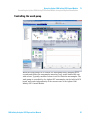
Analytical SFC System
User Manual
Agilent Technologies
Notices
© Agilent Technologies, Inc. 2010 - 2012
Warranty
No part of this manual may be reproduced
in any form or by any means (including electronic storage and retrieval or translation
into a foreign language) without prior agreement and written consent from Agilent
Technologies, Inc. as governed by United
States and international copyright laws.
The material contained in this document is provided “as is,” and is subject to being changed, without notice,
in future editions. Further, to the maximum extent permitted by applicable
law, Agilent disclaims all warranties,
either express or implied, with regard
to this manual and any information
contained herein, including but not
limited to the implied warranties of
merchantability and fitness for a particular purpose. Agilent shall not be
liable for errors or for incidental or
consequential damages in connection
with the furnishing, use, or performance of this document or of any
information contained herein. Should
Agilent and the user have a separate
written agreement with warranty
terms covering the material in this
document that conflict with these
terms, the warranty terms in the separate agreement shall control.
Manual Part Number
G4301-90001
Edition
12/2012
Printed in Germany
Agilent Technologies
Hewlett-Packard-Strasse 8
76337 Waldbronn
This product may be used as a component of an in vitro diagnostic system if the system is registered with
the appropriate authorities and complies with the relevant regulations.
Otherwise, it is intended only for general laboratory use.
receive no greater than Restricted Rights as
defined in FAR 52.227-19(c)(1-2) (June
1987). U.S. Government users will receive
no greater than Limited Rights as defined in
FAR 52.227-14 (June 1987) or DFAR
252.227-7015 (b)(2) (November 1995), as
applicable in any technical data.
Safety Notices
CAUTION
A CAUTION notice denotes a
hazard. It calls attention to an
operating procedure, practice, or
the like that, if not correctly performed or adhered to, could
result in damage to the product
or loss of important data. Do not
proceed beyond a CAUTION
notice until the indicated conditions are fully understood and
met.
Technology Licenses
The hardware and/or software described in
this document are furnished under a license
and may be used or copied only in accordance with the terms of such license.
Restricted Rights Legend
If software is for use in the performance of a
U.S. Government prime contract or subcontract, Software is delivered and licensed as
“Commercial computer software” as
defined in DFAR 252.227-7014 (June 1995),
or as a “commercial item” as defined in FAR
2.101(a) or as “Restricted computer software” as defined in FAR 52.227-19 (June
1987) or any equivalent agency regulation
or contract clause. Use, duplication or disclosure of Software is subject to Agilent
Technologies’ standard commercial license
terms, and non-DOD Departments and
Agencies of the U.S. Government will
WA R N I N G
A WARNING notice denotes a
hazard. It calls attention to an
operating procedure, practice,
or the like that, if not correctly
performed or adhered to, could
result in personal injury or
death. Do not proceed beyond a
WARNING notice until the indicated conditions are fully understood and met.
1260 Infinity Analytical SFC System User Manual
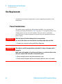
In This Book
In This Book
This Manual discribes all about the Agilent 1260 SFC System.
1 Introduction to Supercritical Fluid Chromatography (SFC)
This chapter provides an overview of the history, theory and benefits of SFC.
2 Site Requirements and Specifications
This chapter provides information on environmental requirements, physical
and performance specifications only for the G4309 Agilent 1260 Infinity
Analytical SFC System.
3 Installing the G4309A Agilent 1260 Infinity SFC System
This chapter provides an overview of the installation and setup of the
hardware and software
4 Configuring the System
How to configure the Agilent 1260 Infinity SFC Analytical system and Agilent
1260 Infinity SFC Control Module in ChemStation.
5 Using the Agilent 1260 Infinity SFC Control Module
This chapter provides information and hints on the use of the SFC System.
6 Maintenance and Repair
In this chapter only the SFC specific procedures are described. For procedures
similar to the Agilent module procedures, please refer to the single module
manuals (G1312C, G1329B, G1316C, G1315/65C, G4225A)
7 Parts for Maintenance
This chapter provides information on parts for maintenance and repair.
1260 Infinity Analytical SFC System User Manual
3
In This Book
8 Identifying Cables
This chapter provides information on cables used with the Agilent 1200
Infinity Series modules.
9 Appendix
This chapter provides addition information on safety, legal and web.
4
1260 Infinity Analytical SFC System User Manual
Contents
Contents
1 Introduction to Supercritical Fluid Chromatography (SFC)
7
History of SFC 8
Theory of SFC 9
Benefits of SFC 10
Common flow path overview for packed column SFC instrumentation
The Agilent 1260 Infinity Analytical SFC System 12
2 Site Requirements and Specifications
11
23
Site Requirements 24
Specifications 28
3 Installing the G4309A Agilent 1260 Infinity SFC System
39
Hardware Installation 40
Software Installation 75
4 Configuring the System
79
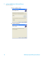
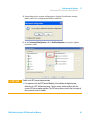
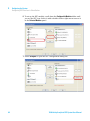
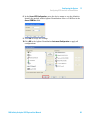
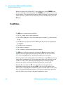
Configuring SFC interface in ChemStation
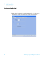
Setting up the Method 84
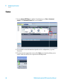
Status 86
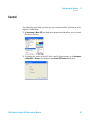
Control 87
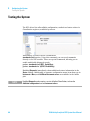
Testing the System 88
80
5 Using the Agilent 1260 Infinity SFC Control Module
89
Powering up the Module 90
Power-up Sequence and Operational Control States 91
Operational Control States 92
Controlling the Agilent 1260 Infinity SFC Control Module through the Agilent
ChemStation 95
Running a method on the SFC system 98
Shutting Down the SFC System 101
1260 Infinity Analytical SFC System User Manual
5
Contents
6 Maintenance and Repair
105
Inspection and Preventative Maintenance Intervals
General Maintenance procedures 108
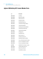
7 Parts for Maintenance
119
Agilent 1260 Infinity SFC Control Module Parts
Agilent Module Parts 121
8 Identifying Cables
106
120
125
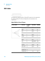
SFC Control Module Cables 126
Overview 127
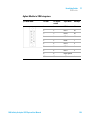
BCD Cables 128
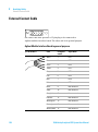
External Contact Cable 130
CAN/LAN Cables 131
RS-232 Cables 132
9 Appendix
133
General Safety Information 134
The Waste Electrical and Electronic Equipment (WEEE) Directive
(2002-96-EC) 137
Radio Interference 138
Sound Emission 139
Solvent Information 140
Agilent Technologies on Internet 141
6
1260 Infinity Analytical SFC System User Manual
1260 Infinity Analytical SFC System User Manual
1
Introduction to Supercritical Fluid
Chromatography (SFC)
History of SFC
8
Theory of SFC
9
Benefits of SFC
10
Common flow path overview for packed column SFC instrumentation
The Agilent 1260 Infinity Analytical SFC System 12
The Agilent 1260 Infinity SFC Control Module (G4301A)
HPLC-SFC binary pump (G4302A) 13
SFC-Autosampler (G4303A) 14
The Column Compartment (G1316C) 21
UV-detection (DAD G1315C and MWD G1365C) 21
Applications 21
Columns 22
11
13
This chapter provides an overview of the history, theory and benefits of SFC.
Agilent Technologies
7
1
Introduction to Supercritical Fluid Chromatography (SFC)
History of SFC
History of SFC
Supercritical fluid chromatography (SFC) was first introduced by Klesper et
al. in 1962 (Klesper, E.; Corwin, A. H.; Turner, D. A. J. Org. Chem. 1962,
27,700.) for the separation and analysis of a porphyrin mixture using open
tubular SFC. The first commercial instruments using packed columns were
available from Hewlett-Packard (HP) in 1982. Since then, several vendors have
developed and commercialized packed column SFC instrumentation for
analytical as well as for preparative separation. SFC is widely accepted for the
separation of chiral compounds and increased user interest has been observed
for a wide spectrum of small to medium sized molecules due to the analysis
speed achieved and the low solvent consumption.
The latest introduction of analytical SFC instrumentation, the Agilent 1260
Infinity SFC Control Module coupled to an Agilent 1260 Infinity Binary LC
system optimized for SFC.
8
1260 Infinity Analytical SFC System User Manual
Introduction to Supercritical Fluid Chromatography (SFC)
Theory of SFC
1
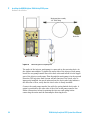
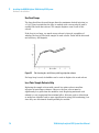
Theory of SFC
EgZhhjgZ
HjeZgXg^i^XVa
;aj^YGZ\^dc
8g^i^XVa
A^fj^Y
EgZhhjgZ
8g^i^XVaEd^ci
Hda^Y
<Vh
8g^i^XVa
IZbeZgVijgZ
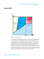
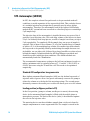
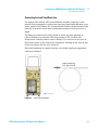
Figure 1
IZbeZgVijgZ
State of a solvent
The superior separation properties achieved by SFC can be explained best by
the thermodynamics of liquids and gases (see the phase diagram in Figure 1
on page 9). Above a critical pressure, liquids can no longer enter the gaseous
state; similarly, above a critical temperature, gases cannot be converted to
liquids. Above both the critical pressure and temperature (characterized by
the critical point), solvents are in the supercritical state. Under these
conditions, the mobile phases exhibit gaseous as well as liquid-like properties.
The major advantages of this state related to chromatography are improved
diffusion characteristics and mass transfer and low viscosity, which result
in high separation efficiency and fast separation capability.
1260 Infinity Analytical SFC System User Manual
9
1
Introduction to Supercritical Fluid Chromatography (SFC)
Benefits of SFC
Benefits of SFC
SFC is widely accepted for the analysis and separation of chiral compounds. In
addition, it gains increasing acceptance as a complementary liquid-based
separation technique to HPLC for high-throughput and high-resolution
analysis of complex mixtures. This is due to the thermodynamic properties of
supercritical fluids, which can be exploited for high throughput and high
efficiency. In addition, the mild thermal conditions also allow for the analysis
of thermally labile compounds. Typically, analysis times and column
re-equilibration are decreased by a factor of 3–5 compared to standard HPLC.
With the increasing costs of organic solvents and the environmental
awareness to minimize toxic waste, production SFC is increasingly accepted
as the “green alternative” to normal phase or reversed phase chromatography,
gaining popularity in method development and UV- and MS-based separation
and purification. A variety of parameters, such as stationary phase selection,
mobile phase composition, modifier type and concentration, column
temperature and system pressure, can be easily manipulated to fulfill
separation requirements by influencing, optimizing and exploiting selectivity
in SFC.
10
1260 Infinity Analytical SFC System User Manual
Introduction to Supercritical Fluid Chromatography (SFC)
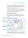
Common flow path overview for packed column SFC instrumentation
1
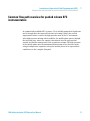
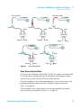
Common flow path overview for packed column SFC
instrumentation
In commercially available SFC systems, CO2 is initially pumped in liquid state
and is brought into the supercritical state by heating it above the critical
temperature before it enters the high-pressure area of the LC instrument.
After high-pressure mixing with a modifier, the mobile phase passes through
the injection loop, where the sample is introduced into the supercritical
stream, and further transported to the separation column. The high pressure
of the mobile phase must be maintained downstream of the detector outlet
using a backpressure regulator to keep the mobile phase in its supercritical
condition over the complete flowpath.
1260 Infinity Analytical SFC System User Manual
11
1
Introduction to Supercritical Fluid Chromatography (SFC)
The Agilent 1260 Infinity Analytical SFC System
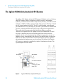
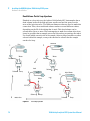
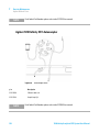
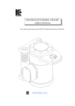
The Agilent 1260 Infinity Analytical SFC System
The Agilent 1260 Infinity Analytical SFC System (G4309A) consists of a binary
HPLC-SFC pump (G4302A), a degasser (G4225A), an SFC Autosampler
(G4303A), a thermostatted column compartment (G1316C), and either a DAD
(G1315C) or MWD (G1365C) equipped with a high pressure SFC flow cell and
the SFC control module (G4301A). The SFC control module, redestills and
preconditions the CO2 by boosting the pressure to just below the column head
pressure, relieving the HPLC-SFC pump of any compression requirements.
This results in low detector noise and significantly higher sensitivity.
Therefore, the Agilent HPLC-SFC pump receives pre-conditioned CO2, and
acts only as metering device for the mobile phase flow and to form the
gradient with the second pump head by adding the appropriate amount of
modifier solvent. Downstream of the detector, the mobile phase is redirected
back into the SFC control module to an integrated back pressure regulator
that maintains the backpressure over the system. The Agilent 1260 Infinity
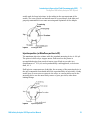
SFC system is completely controlled by Agilent ChemStation software. The
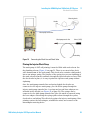
system diagram is shown below:
>cejiIZZ
LVh]ejbe
7EG
[gdbYZiZXidg
id6AH
[gdblVh]hdakZciWdiiaZ
idlVhiZ
id6\^aZciH;8ejbe
DjiejiIZZ
Figure 2
12
Agilent 1260 Infinity Analytical SFC System
1260 Infinity Analytical SFC System User Manual
Introduction to Supercritical Fluid Chromatography (SFC)
The Agilent 1260 Infinity Analytical SFC System
1
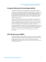
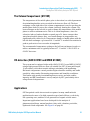
The Agilent 1260 Infinity SFC Control Module (G4301A)
The Agilent 1260 Infinity SFC Control Module is responsible for all tasks
connected to pre- and post-conditioning of the mobile phase. In contrast, flow
rate, mobile phase composition, detection, column temperature and data
analysis are controlled by the modules of the Agilent 1260 Infinity SFC system
in combination with the ChemStation software. This includes metering the
carbon dioxide flow and mixing the modifier into the mobile phase by the
HPLC-SFC binary pump.
In detail, the Agilent 1260 Infinity SFC Control Module uses vapor-phase
carbon dioxide, redestills it to the liquid state and boosts its pressure to just
under the column head pressure. Since the CO2 gas is a very poor solvent,
most contaminants in the carbon dioxide are left in the source, which allows
for the use of inexpensive, beverage-grade CO2, unlike in any other
commercially available instrument. The SFC control module further recollects
the effluent from the UV (or other) detector and controls the backpressure up
to 400 bar over the complete system. In addition, the SFC control module
delivers the wash solvent to flush the fixed (sample) loop of the SFC
autosampler.
HPLC-SFC binary pump (G4302A)
The HPLC-SFC binary pump is equipped with passive inlet valves and with
special seals and pistons to allow for CO2 pumping in channel A while channel
B adds organic modifier for either isocratic or gradient performance.
Pumphead B is also equipped with a purge valve to allow for quick changeover
of the organic modifier.
1260 Infinity Analytical SFC System User Manual
13
1
Introduction to Supercritical Fluid Chromatography (SFC)
The Agilent 1260 Infinity Analytical SFC System
SFC-Autosampler (G4303A)
In SFC, the complete solvent flow path needs to be pressurized under all
conditions to avoid expansion of the supercritical fluid. This excludes the use
of a variable injection loop design that is generally used in other Agilent
autosamplers. Therefore, the autosampler used in the Agilent 1260 Infinity
analytical SFC system has been converted to a fixed loop injector containing a
5 μL sample loop.
The injection loop of the autosampler is installed between two ports of the 2
position/6 port injection valve. The total delay volume of the injector is about
3.3 μL. As with any fixed loop injector, overfill of sample is necessary to inject
5 μL reproducibly. To completely fill the sample loop, an excess of sample is
required. This is about 3 loop volumes (15 μL of the installed loop) of sample
to achieve 95 % of the maximum loop volume. For smaller injection volumes,
the loop needs to be partially filled by sandwiching the sample between two
air bubbles, one on either side, followed by a plug of modifier or other solvent
behind the sample. Default methods for full loop filling are provided, and
should be used as initial injection conditions. The default methods are
automatically loaded in ChemStation.
The recommended temperature setting on the left heat exchanger in order to
achieve minimum noise is typically between 37 °C and 40 °C for G1315C or
G1365C detectors using the 10 mm flow cell. This needs to be optimized
empirically.
Standard ALS configuration: two groove rotor
Most Agilent automated liquid samplers (ALS) use the broken loop mode of
injection with a 2-groove rotor. One groove alternately connects the pump to
either the column or to the back of the metering syringe. The second groove
alternately connects the needle port to either the waste port or to the column.
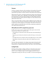
Loading position (or Bypass position in CS)
In the first position, (pump to column; needle port to waste) the metering
device in the automated liquid sampler is filled with the mobile phase at
atmospheric pressure. The back of the device (inlet) is dead-headed against
the rotor in the injection valve.
The metering device can then withdraw sample from a vial or air from the
sample compartment to create segmented flow. The sample is stored in the
14
1260 Infinity Analytical SFC System User Manual
1
Introduction to Supercritical Fluid Chromatography (SFC)
The Agilent 1260 Infinity Analytical SFC System
needle and, for large injections, in the tubing in the arm upstream of the
needle. The rotor, piston seal and all must be in good shape, leak tight and
properly maintained for accurate metering and aspiration of the sample.
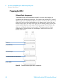
Figure 3
Loading position
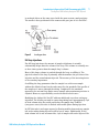
Injection position (or MainPass position in CS)
The maximum injection volume with the standard metering device is 100 μL.
The piston is driven by a stepper motor. Full travel on the piston is
accomplished using thou-sands of motor steps. Each step results in a
displacement of ~0.01 μL, and reproducibility could approach, or be better
than, 0.1 %.
If all injector components are leak tight, the accuracy of the metering device is
the only component that should affect the reproducibility of injections. A leaky
needle port, a worn rotor or stator in the valve, or a worn piston seal in the
metering device are the most likely causes of poor precision, other than
leaking fittings.
Figure 4
Injection position
1260 Infinity Analytical SFC System User Manual
15
1
Introduction to Supercritical Fluid Chromatography (SFC)
The Agilent 1260 Infinity Analytical SFC System
Carryover
Carryover is largely a function of the cleanliness of the outside of the needle,
or of a gap between the rotor and stator caused by wear. In some models,
needle wash is provided to wash the outside of the needle between injections.
When the injection valve is switched to position two (pump to metering device;
needle port to column, Inject or MainPass), the mobile phase passes through
the metering device, down the tubing, through the needle and port and into
the column. The mobile phase pushes the sample out of the needle/tube and
washes these devices out.
There is no wasted sample. All of the sample withdrawn from the sample vial
is injected. The valve is in this position most of the time and is only switched
to position one (Load or Bypass), to load sample. The inside of the tube and
needle, needle port, and valve body are all nearly continuously washed with
fresh mobile phase during the run.
ALS modification for SFC: using the three-groove rotor
In SFC, the two-groove rotor is replaced with a three-groove rotor, and an
external loop is added to the injection valve.
• The needle port is directed to enter either the inlet of the external loop or
to waste.
• The waste port is directed to either the outlet of the loop or to the needle
port.
• The pump is directed to either the inlet of the sample loop or to the column.
• The column is directed to either the outlet of the sample loop or to the
pump.
The inlet of the metering device is no longer connected to the injection valve
but is, instead, connected to an external wash pump. The metering pump
should always be completely filled with the wash solvent, with no air bubbles.
Loading Position
The first position (pump to column, needle port to loop inlet, waste port to
loop outlet) corresponds to the HPLC two-groove rotor load position. The
needle is used to withdraw sample from the sample vial and air from the
compartment in exactly the same way as for HPLC. The same metering device
16
1260 Infinity Analytical SFC System User Manual
1
Introduction to Supercritical Fluid Chromatography (SFC)
The Agilent 1260 Infinity Analytical SFC System
is used and driven at the same speed with the same accuracy and precision.
The needle is then positioned in the same needle port just as it is for HPLC.
Figure 5
Loading position
Full loop injections
For full loop injections, the amount of sample withdrawn is actually
substantially larger than the volume of the loop. This volume is normally two
to three times greater than the sample loop’s volume.
Most of this larger volume is pushed through the loop, overfilling it. The
physical volume of the loop is primarily what determines the precision of the
injection and the actual amount injected. The accuracy of the metering device
is of secondary importance.
Overfilling the loop guarantees that the sample is a midstream sample
without the dilution found on the ends caused by the parabolic flow profile of
the sample as it moves through the tubing. Compared to the standard
approach, the external loop mode wastes sample when maximum precision is
required. However, reproducibility can be identical in both cases.
Modifying the Agilent ALS for SFC adds an additional step when setting up
injections. The needle port and its connecting tubing have approximately 2 μL
of dead volume after the needle and before the sample loop. In HPLC
(two-groove rotor) this tube is flushed with mobile phase during injection.
In SFC this tube is no longer exposed to flowing mobile phase and any sample
left in the tubing during injection will be lost to waste. Additionally, if this
dead volume loss is not accounted for, 2 μL of sample will not be injected. For
1260 Infinity Analytical SFC System User Manual
17
1
Introduction to Supercritical Fluid Chromatography (SFC)
The Agilent 1260 Infinity Analytical SFC System
example, the metering device delivering 5 μL of sample may only result in 3 μL
of sample making it into the sample loop.
Figure 6
Injection position
Partial loop injections
For partial loop injections with the three-groove rotor, the metering device
accuracy is more important. Accuracy and reproduci-bility are determined by
the metering device, not by the loop volume. The most effective way to
accomplish a partial loop injection is to:
• include two air gaps – one before and one after the sample plug. Full fixed
loop injection also has these two air gaps to prevent sample loss as the
needle moves out of the sample vial and into the needle port
• use a careful choice of air volumes to position the sample plug in the middle
of the loop
The air gaps are extremely effective in controlling the shape and volume of the
sample plug. Small air bubbles do not affect the chromatography.
A detailed procedure on how to use the Agilent 1260 Infinity SFC system for
reproducible partial loop injection is described in Technical Note "Injecting
variable volumes using the partial loop fill method with the Agilent 1260
Infinity analytical SFC System" Agilent Technical Overview 5591-0514EN on
www.agilent.com/chem/sfc.
Carryover
For partial loop injections with SFC, the sample is exposed to the inside and
the outside of the needle, the needle port, two grooves, and the sample loop.
One groove and the sample loop are washed by the mobile phase. The other
18
1260 Infinity Analytical SFC System User Manual
1
Introduction to Supercritical Fluid Chromatography (SFC)
The Agilent 1260 Infinity Analytical SFC System
two grooves are washed by the wash pump. The fittings in the injection system
must be leak-tight to prevent drawing air bubbles into the metering device.
Both the two-groove (HPLC) and the three-groove (SFC) rotor settings have six
potential leak spots in common. However, the three-groove setting has one
additional leak spot. If the sample sits in the loop for any extended period of
time, there is the potential for a leaky fitting causing siphoning. The waste line
may be filled with solvent and sample.
Figure 7
Potential leak spots in the loop, waste line, and the low pressure side of the
injection system
If the waste bottle is positioned substantially below the injection valve, gravity
can generate a 1 – 2 psi (0.1 bar) pressure differential between the metering
device and the waste bottle causing the system to siphon if there is a leaky
fitting on the low pressure side of the injection system (metering device, arm,
needle, needle port, loop). If the wash solvent is stored in the solvent cabinet
on top of the Agilent stack, gravity can generate an additional 1 – 2 psi of
pres-sure on the wash pump.
The outlet check valve on the wash pump has a 15 psi spring pushing the ball
into the seat. If this check valve is damaged, there is potential for wash solvent
siphoning through the wash pump then through the metering device, arm,
needle, and needle port, displacing some of the sample from the loop and
causing loss of precision.
A quick check for this condition is simply to put the wash solvent bottle on the
bench below the wash pump. This removes the pressure differential and the
siphoning will stop.
1260 Infinity Analytical SFC System User Manual
19
1
Introduction to Supercritical Fluid Chromatography (SFC)
The Agilent 1260 Infinity Analytical SFC System
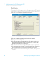
Troubleshooting
Conversion of the ALS two-groove rotor to a three-grove rotor for SFC can only
negatively affect reproducibility and carryover under the following conditions:
1 The user is NOT running the supplied injector program.
Figure 8
Injector program
2 The user is running a standard broken loop injection method.
3 A two-groove rotor is being used.
4 The tube that connects the wash pump in the SFC control module to the
inlet of the metering pump (syringe) in the Agilent ALS is not leak tight,
allowing the metering device to aspirate air.
5 The other end of the tube is not tight, allowing the syringe to aspirate air.
6 The wash pump is not delivering. To check: turn on the wash pump for 30 s
and see if liquid drips out of the waste line from the injection valve.
7 The check valve on the outlet of the wash pump is leaking, allowing solvent
to siphon.
20
1260 Infinity Analytical SFC System User Manual
1
Introduction to Supercritical Fluid Chromatography (SFC)
The Agilent 1260 Infinity Analytical SFC System
The Column Compartment (G1316C)
The temperature of the mobile phase prior to detection is a critical parameter
for minimizing baseline noise recorded in the detector flow cell. The heat
exchanger on the right side of the column compartment is used to pre-heat the
mobile phase before it enters the column, indirectly heating the column. The
heat exchanger on the left side is used to change the temperature of the mobile
phase to achieve minimum noise. This is of crucial importance, since the
refractive index of carbon dioxide responds up to 50 times stronger than
water-based mobile phases; thus, even small changes in temperature can
significantly affect noise levels. Temperature changes of mobile phase with the
left side heat exchanger e.g. between 38 °C and 49 °C resulted in a variation in
peak-to-peak noise of over an order of magnitude.
The recommended temperature setting on the left heat exchanger in order to
achieve minimum noise is typically between 37 °C and 40 °C for G1315C or
G1365C detectors.
UV-detection (DAD G1315C and MWD G1365C)
The system can be equipped either with a DAD (G1315C) or an MWD (G1365C)
using a high pressure detector flow cell suitable for SFC (10 mm path length,
13 μL volume), with short transfer tubing to minimize peak broadening.
Electronic temperature control provides highest baseline stability and stable
sensitivity values under fluctuating temperature and humidity conditions.
This feature aids greatly in minimizing detector noise, and now enables
impurity and EE (enantiomeric excess) analysis by SFC, particularly when
using elevated temperatures.
Applications
SFC has gained a wide interest and acceptance in many small molecule
applications because of its high separation speed and efficiency, selectivity,
low operating costs, and due to low generation of organic solvent waste.
Important applications have been developed for the analysis of
pharmaceutical drugs, natural products, fatty acids, vitamins, pesticides,
lipids and chiral compounds. See Figure 9 on page 22.
1260 Infinity Analytical SFC System User Manual
21
1
Introduction to Supercritical Fluid Chromatography (SFC)
The Agilent 1260 Infinity Analytical SFC System
Columns
In contrast to reversed phase separation, there is no universal stationary
phase available for SFC separations. Most typically used stationary phases are
ethyl pyridine, diol, cyano, amino, Silica and SCX columns. This usually leads
to additional effort to screen different columns in order to achieve optimum
separation. On the other hand, it provides a valuable tool for achieving
different selectivities for a given analyte mixture. A review of column
developments for SFC was recently published by T.Berger, B.Berger &
R.E.Majors in LCGC North America, May 1, 2010
L]ZgZH;8;^ih>c/[gdbcdc"edaVgid]^\]an"X]Vg\ZY
EZciVcZ
:i]Zg
:hiZgh
6aXd]dah
6cVa^cZh
6b^YZh
>cdg\Vc^X
^dchAVg\Z
6a^e]Vi^XVb^cZh6be]diZg^Xh EZei^YZh egdiZ^ch9C6$GC6
6X^YhEg^bVgn
H;8/ejgZ8D '
H;8/ejgZ8D' bdY^[^Zg
H;8/ejgZ8D' bdY^[^Zg VYY^i^kZh
H;8/ejgZ8D' bdY^[^Zg VYY^i^kZh lViZg
>dceV^g^c\
GZkZghZYE]VhZ=EA8
>dcX]gdbVid\g\gV]n
CdgbVaE]VhZ=EA8
>dcZmX]Vc\Z
Figure 9
22
Where SFC Fits In: from non-polar to highly-charged
1260 Infinity Analytical SFC System User Manual
1260 Infinity Analytical SFC System User Manual
2
Site Requirements and Specifications
Site Requirements 24
Power Considerations
Power Cords 25
Bench space 26
Environment 27
Ventilation 27
24
Specifications 28
System Specifications 28
Specifications 28
Agilent 1260 Infinity System
32
This chapter provides information on environmental requirements, physical and
performance specifications only for the G4309 Agilent 1260 Infinity Analytical
SFC System.
Agilent Technologies
23
2
Site Requirements and Specifications
Site Requirements
Site Requirements
A suitable environment is important to ensure optimal performance of the
instrument.
Power Considerations
The module power supply has wide ranging capability. It accepts any line
voltage in the range described in Table 5 on page 33. Consequently there is no
voltage selector in the rear of the module. There are also no externally
accessible fuses, because automatic electronic fuses are implemented in the
power supply.
WA R N I N G
Hazard of electrical shock or damage of your instrumentation
can result, if the devices are connected to a line voltage higher than specified.
➔ Connect your instrument to the specified line voltage only.
WA R N I N G
The module is partially energized when switched off, as long as the power cord is
plugged in.
Repair work at the module can lead to personal injuries, e.g. electrical shock, when
the cover is opened and the module is connected to power.
➔ Always unplug the power cable before opening the cover.
➔ Do not connect the power cable to the instrument while the covers are removed.
24
1260 Infinity Analytical SFC System User Manual
2
Site Requirements and Specifications
Site Requirements
CAUTION
Inaccessible power plug.
In case of emergency it must be possible to disconnect the instrument from the power
line at any time.
➔ Make sure the power connector of the instrument can be easily reached and
unplugged.
➔ Provide sufficient space behind the power socket of the instrument to unplug the
cable.
Power Cords
Different power cords are offered as options with the module. The female end
of all power cords is identical. It plugs into the power-input socket at the rear
of the module. The male end of each power cord is different and designed to
match the wall socket of a particular country or region.
WA R N I N G
Absence of ground connection or use of unspecified power cord
The absence of ground connection or the use of unspecified power cord can lead to
electric shock or short circuit.
➔ Never operate your instrumentation from a power outlet that has no ground
connection.
➔ Never use a power cord other than the Agilent Technologies power cord designed
for your region.
WA R N I N G
Use of unsupplied cables
Using cables not supplied by Agilent Technologies can lead to damage of the
electronic components or personal injury.
➔ Never use cables other than the ones supplied by Agilent Technologies to ensure
proper functionality and compliance with safety or EMC regulations.
1260 Infinity Analytical SFC System User Manual
25
2
Site Requirements and Specifications
Site Requirements
Bench space
Agilent 1260 Infinity SFC Control Module
The Agilent 1260 Infinity SFC Control Module requires approximately 1 foot of
linear bench space immediately adjacent to the target Agilent 1260 Infinity
system stack. Approximately 5 inches of free space is required behind the
instrument for cable access and adequate air flow for ventilation. Similar
access to the rear of the 1260 Infinity system is also required to install cables
and interface cards. As mentioned earlier, for optimal performance, the rear
air space should not be heated significantly above room temperature by the
exhaust of other instrumentation in the lab; rather, hot exhaust should be
vented or directed upward from the instrument.
The module is designed to be installed on either side of the 1260 Infinity
system stack with sufficient high pressure transfer tubing to attach to a
double-stacked system. If the 1260 Infinity system is attached to a split-flow
detector such as Mass Spec or ELSD, the Agilent 1260 Infinity SFC Control
Module should be positioned on the opposite side of the stack. Shelves
overhanging the Agilent 1260 Infinity SFC Control Module should provide a
minimum of 6 inches of clearance to allow access to the rear power switch.
Finally, the PC system interface to the Agilent 1260 Infinity SFC Control
Module is USB 2.0. A six-foot cable is supplied with the system. The CPU must
be placed within range of this cable. Alternately, the user may supply an
extended length USB cable not to exceed 16 feet.
While the Agilent 1260 Infinity SFC Control Module can exist on either side of
the 1260 Infinity system, it is often easier to locate it on the left side. For more
specification details see “Agilent 1260 Infinity SFC Control Module” on
page 28
Agilent modules
The dimensions and weight of your module (see “Agilent 1260 Infinity
System” on page 32) allow it to be placed on almost any laboratory bench. It
needs an additional 2.5 cm (1.0 inches) of space on either side and
approximately 8 cm (3.1 inches) at the rear for the circulation of air and
electric connections.
The module should be operated in a horizontal position.
26
1260 Infinity Analytical SFC System User Manual
2
Site Requirements and Specifications
Site Requirements
If a Thermostatted Autosampler is installed, an additional 25 cm (10 inches)of
space on either side for the circulation of air, and approximately 8 cm
(3.1 inches) at the rear is required for electrical connections.
If a complete 1260 Infinity system is to be installed on the bench, make sure
that the bench is designed to carry the weight of all the modules. For a system
including the Thermostatted Autosampler it is recommended to position the
modules in two stacks.
Environment
CAUTION
Condensation within the module
Condensation will damage the system electronics.
➔ Do not store, ship or use your module under conditions where temperature
fluctuations could cause condensation within the module.
➔ If your module was shipped in cold weather, leave it in its box and allow it to warm
slowly to room temperature to avoid condensation.
Ventilation
WA R N I N G
Waste tube has to be connected to hood or vent
➔ The effluent from a supercritical fluid chromatograph may contain vaporized, toxic
solvents. Never vent into an enclosed, occupied space. Always vent into a fume
hood or vent to the outside.
1260 Infinity Analytical SFC System User Manual
27
2
Site Requirements and Specifications
Specifications
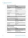
Specifications
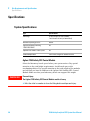
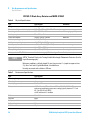
System Specifications
Type
Specifications
Flow range
0.1 mL/min to 5 mL/min (settable),
1 mL/min to 5 mL/min (recommended)
Maximum operating pressure
600 bar
Upgrade possibility of exisiting
1100/1200/1260 LC
Yes
Option for SFC/UHPLC in one system
Yes
Unattended operation
Leak sensors, diagnostic software features
Agilent 1260 Infinity SFC Control Module
Select the laboratory bench space before your system arrives. Pay special
attention to the total height requirements. Avoid bench space with
overhanging shelves. Pay special attention to the total weight of the modules
and solvents you have in addition to the Agilent 1260 Infinity SFC Control
Module. Make sure that your laboratory bench can support this weight.
WA R N I N G
Personal injury
The Agilent 1260 Infinity SFC Control Module module is heavy.
➔ Enlist the aid of a co-worker to share the lifting load to avoid personal injury.
28
1260 Infinity Analytical SFC System User Manual
Site Requirements and Specifications
Specifications
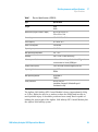
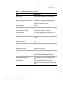
Table 1
2
Physical Specifications (G4301A)
Type
Specification
Weight
26 kg
56 lbs
Dimensions (height × width × depth)
60 cm x 26 cm x 48 cm
23 in x 10 in x 18 in
Line voltage
100 - 240 VAC, ±10 %
Line frequency
50 - 60 Hz, ±5 %
Power consumption
700 VA Max
Operating temperature
15 - 30 °C
Non-operating temperature
-40 - 70 °C
Humidity
<95 %, at 40 °C, Non-condensing
Laboratory ventilation
minimum 6 air exchanges/hr for lab air; CO2 monitor
recommended w/ alarm @ 5000 ppm
Exhaust vent capacity
>20 L/min with sustained negative pressure
Operating altitude
up to 2000 m
6500 ft
Non-operating altitude
up to 4600 m
14950 ft
Safety standards
IEC, EN, CSA, UL
Installation Category II, Pollution Degree II
For Indoor Use only
The Agilent 1260 Infinity SFC Control Module is heavy (approximately 26 kg
or 56 lbs). Enlist the aid of a co-worker to share the lifting load in order to
avoid possible injury. It should be positioned on a sturdy bench capable of
holding the total weight of the Agilent 1260 Infinity SFC Control Module plus
the Agilent 1260 Infinity system.
1260 Infinity Analytical SFC System User Manual
29
2
Site Requirements and Specifications
Specifications
Table 2
Chemical Specifications (G4301A)
Type
Specifications
Inlet CO2 bulk purity
>99.99 % vapor; >99.999 % liquid
Inlet CO2 phase
vapor from non-dip-tube high pressure cylinder; liquid
from commercial CO2 delivery system
Inlet CO2 supply pressure
40 - 70 bar
580 - 1000 psi
Inlet CO2 temperature
15 - 30 °C
Wash solvent
HPLC grade alcohol
Liquid coolant
30 % propylene glycol in deionized water; proprietary
antioxidants; red dye added for safety
Coolant volume
< 280 mL
Table 3
Wetted Materials Specifications (G4301A)
Type
Specifications
High pressure flow path
300 and 400 series stainless steel PEEK, carbon filled
PEEK PTFE, PTFE, FEP, CTFE UHMW PE ruby,
sapphire, ceramic
Low pressure flow paths [waste, wash
pump, leak tray]
316 stainless steel PEEK PTFE, PTFE, FEP, CTFE CPE;
LDPE Tygon PVC
Vapor exhaust
Tygon PVC
Performance Specifications
Table 4
30
Performance Specifications (G4301A)
Type
Specifications
Hydraulic system
Single piston with proprietary motor control
Total hydraulic volume
<5 mL @ pressure <70 bar
<25 mL @ pressure up to 400 bar
1260 Infinity Analytical SFC System User Manual
2
Site Requirements and Specifications
Specifications
Table 4
Performance Specifications (G4301A)
Type
Specifications
Chiller system
Thermoelectric cooling with secondary air/liquid
cooling circuit
Back Pressure Regulation (BPR) system
Low volume diaphragm type with proprietary drive
control; replaceable BPR head assy; No recalibration
required after head replacement
Chiller temperature
-20 – 9 °C
Booster pump speed range
0 – 6000 steps/sec average step rate
Booster pump pressure range
100 – 400 bar up to 5 mL/min demand
Pressure pulsation
<2 % amplitude at pump speed >300 steps/sec and
outlet pressure >100 bar
BPR thermal range
40
- 70 °C
104 – 158 F
BPR thermal precision
±1 °C
BPR pressure range
100 – 400 bar
Backpressure accuracy
±1 %
Backpressure precision
±0.5 bar (±0.2 bar typical)
Backpressure thermal precision
±1 °C
Control and data evaluation
Agilent ChemStation for LC with SFC Control Module
driver; SFC Control Module Diagnostic Program
Analog in pressure monitoring
1 V FS; one input; range set by calibration to host
pump
Communications
USB 2.0; APG Remote: ready, start, stop and
shut-down signals; relay contact closure [wash pump
only]
1260 Infinity Analytical SFC System User Manual
31
2
Site Requirements and Specifications
Specifications
Agilent 1260 Infinity System
WA R N I N G
Unspecified Conditions
Operating the instrumentation under conditions other than its intended use might
result in a potential safety hazard or might damage the instrumentation.
➔ Never operate your instrumentation under conditions other than those specified by
the vendor.
32
1260 Infinity Analytical SFC System User Manual
Site Requirements and Specifications
Specifications
2
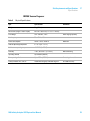
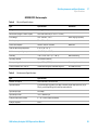
G4225A Vacuum Degasser
Table 5
Physical Specifications
Type
Specification
Weight
5 kg (11 lbs)
Dimensions (height × width × depth)
80 x 345 × 435 mm (3.1 x 13.5 × 17 inches)
Line voltage
100 – 240 VAC, ± 10%
Line frequency
50 or 60 Hz, ± 5%
Power consumption
30 VA / 30 W / 102 BTU
Ambient operating temperature
0 – 55 °C (32 – 131 °F)
Ambient non-operating temperature
-40–70 °C (-4–158 °F)
Humidity
< 95%, at 25–40 °C (77–104 °F)
Operating altitude
Up to 2000 m (6562 ft)
Non-operating altitude
Up to 4600 m (15091 ft)
For storing the module
Safety standards: IEC, CSA, UL
Installation category II, Pollution degree 2
For indoor use only.
1260 Infinity Analytical SFC System User Manual
Comments
Wide-ranging capability
Maximum
Non-condensing
33
2
Site Requirements and Specifications
Specifications
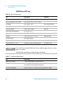
G1315C/D Diode Array Detector and MWD G1365C
Table 6
Physical Specifications
Type
Specification
Comments
Weight
11.5 kg (26 lbs)
Dimensions (height × width × depth)
140 x 345 x 435 mm (5.5 x 13.5 x 17 inches)
Line voltage
100 – 240 VAC, ± 10 %
Line frequency
50 or 60 Hz, ± 5 %
Wide-ranging capability
Power consumption
160 VA / 160 W / 546 BTU
Ambient operating temperature
0–55 °C (32–131 °F)
Ambient non-operating temperature
-40 – 70 °C (-4 – 158 °F)
Humidity
< 95 %, at 25 – 40 °C (77 – 104 °F)
Maximum
Non-condensing
Operating altitude
Up to 2000 m (6562 ft)
Non-operating altitude
Up to 4600 m (15091 ft)
For storing the module
Safety standards: IEC, CSA, UL
Installation category II, Pollution degree 2
For indoor use only.
NOTE
ASTM: “Standard Practice for Testing Variable Wavelength Photometric Detectors Used in
Liquid Chromatography”.
Reference conditions: cell path length 10 mm, time constant 1 s (equal to response time
2 s), flow 1 mL/min LC-grade Methanol, slit width 4 mm.
Linearity measured with caffeine at 265 mm.
Table 7
Performance Specifications
Type
Specification
Wave length range
190 – 950 nm
Wavelenghth accuracy
±1 nm
Linearity range
2.0 AU at 265 nm
Noise, wet
±0.05 mAU under SFC conditions at 254 nm, 20 % MetOH/80 % CO2 at
optimum preconditioning temperature setting (typically between 37 °C and
40 °C for G1315C or G1365C).
±0.007 mAU under LC condition
Drift
0.9 mAU/h
Data rate
80 Hz
Cell pressure limit
400 bar
Cell path length
10 mm
Cell volume
13 µL
34
1260 Infinity Analytical SFC System User Manual
Site Requirements and Specifications
Specifications
2
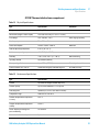
G4303A SFC Autosampler
Table 8
Physical Specifications
Type
Specification
Weight
15.5 kg (34.2 lbs)
Dimensions (height × width × depth)
200 x 345 x 440 mm (8 x 13.5 x 17 inches)
Line voltage
100 – 240 VAC, ± 10 %
Line frequency
50 or 60 Hz, ± 5 %
Power consumption
300 VA / 200 W / 683 BTU
Ambient operating temperature
4–55 °C (41–131 °F)
Ambient non-operating temperature
-40 – 70 °C (-4 – 158 °F)
Humidity
< 95 %, at 25 – 40 °C (77 – 104 °F)
Operating altitude
Up to 2000 m (6562 ft)
Non-operating altitude
Up to 4600 m (15091 ft)
For storing the module
Safety standards: IEC, CSA, UL
Installation category II, Pollution degree 2
For indoor use only.
Table 9
Comments
Wide-ranging capability
Maximum
Non-condensing
Performance Specifications
Type
Specification
Number of samples
100 x 2 mL vials, 30 x 6 mL vials
Injection volume
5 µL for full loop injections (5 µL loop as default) larger loops possible (10 µL,
20 µL), partial loop filling for smaller injection volumes
Injection principle
Fixed loop
Injection precision
<0.3 % RSD for 5 µL
Sample temperature control
4 – 40 °C with sample thermostat
Sample carryover
0.05 %
1260 Infinity Analytical SFC System User Manual
35
2
Site Requirements and Specifications
Specifications
G4302A Binary SFC Pump
Table 10
Physical Specifications
Type
Specification
Weight
15.5 kg (34 lbs)
Dimensions (height × width × depth)
180 x 345 x 435 mm (7 x 13.5 x 17 inches)
Line voltage
100 – 240 VAC, ± 10 %
Line frequency
50 or 60 Hz, ± 5 %
Power consumption
220 VA, 74 W / 253 BTU
Ambient operating temperature
0–55 °C (32–131 °F)
Ambient non-operating temperature
-40 – 70 °C (-4 – 158 °F)
Humidity
< 95 %, at 25 – 40 °C (77 – 104 °F)
Operating altitude
Up to 2000 m (6562 ft)
Non-operating altitude
Up to 4600 m (15091 ft)
For storing the module
Safety standards: IEC, CSA, UL
Installation category II, Pollution degree 2
For indoor use only.
NOTE
Comments
Wide-ranging capability
Maximum
Non-condensing
For use with flow rates below 500 µL/min, or for use without damper and mixer, a vacuum
degasser is required.
All specification measurements are done with degassed solvents.
Table 11
Performance Specifications
Type
Specification
Number of co-solvents
1, with SSV pump option 3, with external SSV 12
Precision of flow rate
Same as G1312B, ≤0.07 %0.07 RSD or ≤0.02 min SD, whatever is greater based
on retention time at constant room temperature
Precision of composition
Same As G1312B, <0.15 % RSD or <0.04 min SD whatever is greater
36
1260 Infinity Analytical SFC System User Manual
Site Requirements and Specifications
Specifications
2
G1316C Thermostatted column compartment
Table 12
Physical Specifications
Type
Specification
Weight
11.2 kg (22 lbs)
Dimensions (height × width × depth)
140 x 345 x 435 mm (5.5 x 13.5 x 17 inches)
Line voltage
100 – 240 VAC, ± 10 %
Line frequency
50 or 60 Hz, ± 5 %
Power consumption
320 VA / 150W / 512 BTU
Ambient operating temperature
0–55 °C (32–131 °F)
Ambient non-operating temperature
-40 – 70 °C (-4 – 158 °F)
Humidity
< 95 %, at 25 – 40 °C (77 – 104 °F)
Operating altitude
Up to 2000 m (6562 ft)
Non-operating altitude
Up to 4600 m (15091 ft)
For storing the module
Safety standards: IEC, CSA, UL
Installation category II, Pollution degree 2
For indoor use only.
Table 13
Comments
Wide-ranging capability
Maximum
Non-condensing
Performance Specifications
Type
Specification
Column
Up to 300 mm length x 4.6 mm ID (or less)
Column capacity
Up to 3, with additional 2 x TCCs up to 9
Switching valve
Optional (2/6, 2/10, 8/9, 6 column selector)
Temperature range
Ambient -10 °C to 100 °C
Column compartement temperature
accuracy
±0.5 °C
Column compartement temperature
stability
±0.05 °C
Active solvent pre-heating and
post-conditioning
As standard
Automated method development
Optional
1260 Infinity Analytical SFC System User Manual
37
2
38
Site Requirements and Specifications
Specifications
1260 Infinity Analytical SFC System User Manual
1260 Infinity Analytical SFC System User Manual
3
Installing the G4309A Agilent 1260
Infinity SFC System
Hardware Installation 40
General Procedures 40
Installing Agilent 1260 Infinity SFC Control Module (G4301A)
Preparing the HPLC 62
43
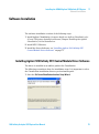
Software Installation 75
Installing Agilent 1260 Infinity SFC Control Module Driver
Software 75
This chapter provides an overview of the installation and setup of the hardware
and software
Agilent Technologies
39
3
Installing the G4309A Agilent 1260 Infinity SFC System
Hardware Installation
Hardware Installation
General Procedures
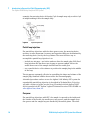
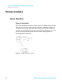
Proper use of wrenches
Some of the plumbing connections require a nut to be tightened onto a fitting.
There are often two sets of flats next to each other. Attempting to tighten the
nut without securing the other part of the fitting with a second wrench can
result in loosening yet another connection upstream or downstream. It is best
practice to always hold the fitting with one wrench while tightening or
loosening another connection.
Figure 10
40
Proper tightening of Fittings
1260 Infinity Analytical SFC System User Manual
Installing the G4309A Agilent 1260 Infinity SFC System
Hardware Installation
3
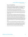
Compression (Swaged Fittings)
The fittings used in the Agilent 1260 Infinity SFC Control Module are Valco.
Fittings used in all Agilent modules are Swagelok. Use the appropriate fitting
as recommended by the equipment manufacturer. The recommended
tightening procedure to install new fittings is to tighten the nut finger tight,
then an additional 1/4 to 1/2 turn to seal. In general, previously swaged
fittings need only an additional 1/8th turn once finger tight.
In Supercritical Fluid Chromatography, the fluid has 1/10th the viscosity of
water, so this may not be tight enough. All connections should be checked for
leaks and tightened further if necessary. Soapy water or Snoop make it easy to
find leaks if carbon dioxide is in the fluid. Tiny bubbles appear in the liquid
around the fitting.
Each fitting should be individually and carefully installed. The depth of the
tube inside the fitting is very important. If the tube pilot (length beyond the
ferrule end) is too long, the fitting can leak or, after excessive tightening, bind
permanently. If the pilot is too short, a poorly swept volume can be created.
This poorly swept volume will create noticeable chromatographic tailing. If the
pilot is much too short, the fitting could fail under use. Pilot depths are not
always interchangeable between fittings. It is a best practice to swage a tube in
the fitting in which it will be used. It is best to provide some light force to hold
the tube in the fitting and prevent the tube from exiting while tightening the
fitting.
Excessive force can result in breakage of some components, and should
obviously be avoided. It may be more expedient to replace the whole fitting if
one of the connections fails to seal. You may notice that some of the more
expensive components (such as a pressure transducer) have a less expensive
fitting mounted to them to act as a sacrificial fitting. Connections should be
made to the less expensive component, and repetitive removal and
replacement to one of the more expensive fittings should be avoided.
1260 Infinity Analytical SFC System User Manual
41
3
Installing the G4309A Agilent 1260 Infinity SFC System
Hardware Installation
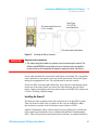
Cji
E^adi9Zei]
;ZggjaZ
IjW^c\
Compression fittings used in the
Agilent 1260 Infinity SFC Control
Module use a nut and ferrule. As
the nut is tightened the ferrule
compresses on the tubing creating
a leak-tight seal
When correctly installed, there is
minimal additional volume. All
volume is well swept.
When improperly set, the pilot
does not fill the fitting, leading to
additional poorly swept volumes.
If over-tightened, the ferrule can
compress the tubing and cause
sufficient deformation to prevent
removal of the fitting.
Figure 11
42
Compression fittings
1260 Infinity Analytical SFC System User Manual
Installing the G4309A Agilent 1260 Infinity SFC System
Hardware Installation
3
Installing Agilent 1260 Infinity SFC Control Module (G4301A)
CAUTION
Early connection may damage the instrument
➔ Do not connect AC power or interconnection cables or gas tubing to the Agilent
1260 Infinity SFC Control Module until these installation procedures direct you to do
so.
Preparation
Locate all modules, devices and supporting equipment before continuing.
Ensure that the supply tubing can reach a physically secured source of CO2.
Ensure that adequate venting is available and within reach of supplied waste
systems.
This document describes a particular order of plumbing the system, with
plumbing and electrical connections described last. These operations are
performed at the rear of the systems. Depending upon your individual
installation, you may wish to perform operations at the rear of the
instruments first. This is perfectly acceptable, provided you can maintain
access to supply connections to ensure integrity and leak tightness of fittings
and connections.
1260 Infinity Analytical SFC System User Manual
43
3
Installing the G4309A Agilent 1260 Infinity SFC System
Hardware Installation
Unpacking the Agilent 1260 Infinity SFC Control Module
Damaged Packaging
When you receive your Agilent 1260 Infinity SFC Control Module (G4301A),
inspect the shipping boxes for any signs of damage. If the shipping container
or cushioning material is damaged, notify the carrier and save the shipping
material for inspection. Save all materials until the contents have been
checked for completeness and the instrument has been mechanically and
electrically checked.
CAUTION
Signs of damage
➔ If there are signs of damage to the module, please do not attempt to install or use
the instrument.
Delivery Checklist
Compare the delivery checklist with the contents of the shipping boxes to
ensure completeness of the shipment.
For parts identification see “Parts for Maintenance” on page 119. Please
report missing or damaged parts to your local Agilent Technologies
representative.
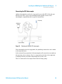
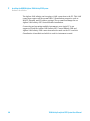
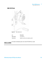
Connecting the Waste system to the SFC control module BPR Outlet
The Agilent 1260 Infinity SFC Control Module has a waste bottle located
outside of the cabinet. It can be located anywhere easily accessible and visible
within the range of the supplied tubing. The waste bottle serves multiple
purposes and collects liquid waste from multiple sources. The primary
purpose is to separate the gaseous and liquid waste from the outlet of the BPR
(system) in such a manner that the gaseous waste can be appropriately vented
outside of the lab environment. The waste bottle has input and output ports
located above any collected liquids. The mixed stream enters the waste bottle
and the gaseous stream exits from the spout.
NOTE
44
Proper system operation requires adequate space in the waste bottle to allow gaseous exit.
It is the responsibility of the operator to ensure that the waste bottle is empty before
beginning operation of the SFC control module, and to monitor and empty the waste bottle
as needed during usage. This is not a warning.
1260 Infinity Analytical SFC System User Manual
3
Installing the G4309A Agilent 1260 Infinity SFC System
Hardware Installation
H;8XdcigdabdYjaZLVhiZA^cZ
&$&+^cX]iZ[adc
IjW^c\In\dc
($-&$)>9
KZciZYLVhiZA^cZ
H;8XdcigdabdYjaZLVhiZ7diiaZ
Figure 12
WA R N I N G
Installing the Waste Container
Exposure to toxic substances
➔ The vapor exiting the module may contain several percent organic solvent. The
effluent should NEVER be vented directly into an enclosed space occupied by
humans because of the potential for long-term exposure to toxic substances.
Locate and assemble the waste bottle and Tygon vent tubing. The vent tubing
can be placed over the spout on the top of the waste bottle. Route the Tygon
tubing to an appropriate vent. The system must be actively vented.
Locate the SFC control module Waste line. Insert the free end through a hole
in the top of the waste bottle cap. Insert the tube half-way into the waste
bottle. Connect the fitting end to the outlet union on the BPR. This union uses
a 10-32 CPI fitting. Tighten snugly.
Installing the Flowcell
The back pressure regulator exists after any detectors in the HPLC system
Thus, the detector flow cells (or splitter in the case on an ELSD or Mass
Spectrometer), operate at an elevated pressure relative to HPLC.
Agilent Technologies offers a Diode Array Detector (DAD) flow cell that has
been extensively optimized for use in Supercritical Fluid Chromatography
(SFC). This cell is pressure-rated and tested to 400 bar. It contains extensive
1260 Infinity Analytical SFC System User Manual
45
3
Installing the G4309A Agilent 1260 Infinity SFC System
Hardware Installation
thermal conditioning not found in standard HPLC flow cells. Agilent
Technology’s cell is highly recommended for SFC usage.
The flow cell should already be installed in the DAD/MWD. Carefully examine
the inlet and outlet ports of the cells to ensure that flow is in the correct
direction. In the DAD/MWD, the outlet port is normally located below the inlet
port on the connection block.
The inlet port of the DAD/MWD flow cell enters the stationary portion of the
handle. This stationary bar acts as an initial thermal conditioning zone.
Normally, this port has a male fitting. The outlet port connects directly to the
cylindrical portion of the flow cell. Normally, this connection has a female
fitting.
Figure 13
CAUTION
DAD SFC Flowcell
Damage to the flowcell
➔ Verify that the cell installed in the detector is capable of the high pressures used in
Supercritical Fluid Chromatography (SFC). Exposing a standard 1260 Infinity flow
cell to high pressures will result in leakage or damage to the cell.
46
1260 Infinity Analytical SFC System User Manual
Installing the G4309A Agilent 1260 Infinity SFC System
Hardware Installation
3
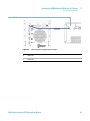
Connecting the BPR to the 1260 Infinity stack
Connect the Agilent 1260 Infinity SFC Control Module return transfer tube to
the outlet block of the detector. This tube can then be routed out the concave
opening in the bottom of the detector behind the detector cover. The return
transfer tube should then be routed to the space between the 1260 Infinity
stack and the Agilent 1260 Infinity SFC Control Module. Move the tube
upward between the units and through the upper tee-slot on the side cover of
the Agilent 1260 Infinity SFC Control Module. The return transfer tube can
then be fastened in the right port of the tee in the lower center of the BPR
drawer.
GZijgcigVch[Zga^cZ
Figure 14
Connecting the SFC control module return Line
1260 Infinity Analytical SFC System User Manual
47
3
Installing the G4309A Agilent 1260 Infinity SFC System
Hardware Installation
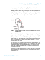
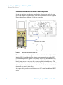
Optimized Agilent 1290 Infinity Thermostatted column compartment
Plumbing
Supercritical Fluid Chromatography (SFC) is susceptible to increased noise
due to poor thermal matching of components within the Agilent 1260 Infinity
stack. (The refractive index of carbon dioxide is 50 times more susceptible to
temperature changes than water. Consequently, thermal control in SFC is
extremely important). The Agilent 1290 Infinity Thermostatted Column
Compartment (TCC) contains two thermal conditioning zones that can greatly
increase system performance by matching temperatures of the mobile phase
to the modules being used.
Each of these zones contains internal transfer lines that can be used to
thermally condition the fluid flowing through them. The two zones exist on the
left and right side blocks within the TCC.
The block on the right side has a 6 μL internal conditioning volume that is
used to precondition the mobile phase before it enters the column. When using
150 mm or shorter columns, place them in the right side of the oven. This zone
is used to precondition the fluid to column temperature and provide thermal
control of the column.
The left side block is plumbed with the effluent from the column. The purpose
of the left side block is to independently match the temperature of the mobile
phase to the optimum temperature for the detector. In order to achieve
minimum noise it is important to use the optimum conditioning temperature
prior to detection (typically between 37 °C and 40 °C for G1315C)
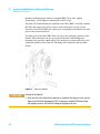
AZ[i]ZViZmX]Vc\ZgVY_jhiZYid
dei^b^hZYZiZXidgcd^hZedhiXdajbc#
Figure 15
48
G^\]i]ZViZmX]Vc\Zg^hjhZYid
VY_jhiiZbeZgVijgZegZ"Xdajbc#
I]^hiZbeZgVijgZVY_jhibZci]Vh
Z[[ZXihdchZaZXi^k^in
Plumbing the Agilent 1290 Infinity Thermostatted column compartment
1260 Infinity Analytical SFC System User Manual
Installing the G4309A Agilent 1260 Infinity SFC System
Hardware Installation
3
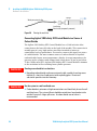
Connecting the SFC Autosampler
Agilent Autosamplers need to be converted for use with SFC. If this has not
already been done, refer to the installation and upgrade section of the
Autosampler compatibility kit for specific instructions.
[gdbejbe
cZZYaZhZVi
XdciV^cZYlVhiZ
Figure 16
idXdajbc
Plumbing the G4203A SFC Autosampler
If the autosampler has been upgraded, the plumbing connections can be made
to the injection valve.
In the external loop operation of the autosampler, all connections are made on
the injection valve as shown. Port 1 is connected to the inlet of the right side
(column pre-heater) thermal conditioning block of the oven.
Port 6 is connected to the output flow from the binary pump.
1260 Infinity Analytical SFC System User Manual
49
3
Installing the G4309A Agilent 1260 Infinity SFC System
Hardware Installation
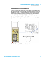
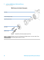
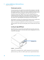
Connecting the Booster to the Agilent 1260 Infinity system
Locate the stainless steel booster transfer line. Connect one end to the top
port of the output tee on the center right side of the booster drawer. Tighten
finger tight with an additional 1/8th turn as needed.
EjbeigVch[Zga^cZVhhZbWan
Figure 17
Connecting the Booster outlet line
This tube can be routed through the tee slots on the side of the Agilent 1260
Infinity SFC Control Module. The tube is routed upward between the SFC
control module and the Agilent 1260 Infinity stack to the bottom side of the
binary pump. The tube is then routed horizontally to the bottom center of the
binary pump where it can enter the concave opening behind the cover. The
tube should then be routed to the left side of the pump beneath the Channel A
(left side). The end of the booster transfer tube can then be installed with the
adapter in the passive inlet valve.
Any spare tubing can be located between the SFC control module and HPLC
stack.
50
1260 Infinity Analytical SFC System User Manual
Installing the G4309A Agilent 1260 Infinity SFC System
Hardware Installation
3
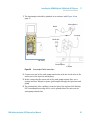
The injector wash pump
The wash pump is required only with autosamplers normally operated as
broken loop autosamplers converted to external loop autosamplers. The
injector wash pump requires a source of wash solvent. This wash solvent is
used to prime the injector system to ensure proper operation while aspirating
sample. If the metering device in the autosampler is not filled with solvent, it
can cavitate and yield anything between poor area reproducibility to no peaks
(no actual injection). The wash pump also washes the injection system (needle
interior, needle seat, injection valve, and sample loop) before and after each
injection.
The injector wash pump is connected to a bottle filter (supplied) through the
wash pump inlet line. The wash pump inlet line is connected to the lower port
on the injector wash pump located on the left side of the BPR drawer. The
other end should be connected to the bottle filter. The filter can then be placed
in a user-supplied wash solvent bottle.
The wash solvent bottle can be left on the bench or placed in the 1200 Infinity
Series solvent cabinet. The wash pump is connected to the metering device
(syringe pump) through a check valve intended to prevent siphoning. The
operation of the check valve should be verified to ensure it is not leaking,
because this can cause a loss of injection precision.
1260 Infinity Analytical SFC System User Manual
51
3
Installing the G4309A Agilent 1260 Infinity SFC System
Hardware Installation
LVh]ejbe^caZiVhhZbWan
&$-IZ[adcIjW^c\
7diiaZ[^aiZg
Figure 18
Connecting the wash pump inlet
The outlet of the injector wash pump is connected to the metering device in
the Agilent autosampler. To plumb the outlet side of the injector wash pump,
locate the was pump transfer line with check valve and install it in the upper
port of the injector wash pump. Flow through the wash pump is in the upward
direction. The injection wash system will not function if the check valve is
improperly installed. An arrow embossed on the check valve body indicates
the direction of flow; verify that the check valve is firmly installed.
Connect the wash pump transfer line with the spring loaded check valve. A
union is provided on the other side of the of the wash pump transfer line.
Follow instructions below for priming the injector wash pump before
connecting the union and the autosampler metering device.
52
1260 Infinity Analytical SFC System User Manual
Installing the G4309A Agilent 1260 Infinity SFC System
Hardware Installation
3
BZiZg^c\YZk^XZ
CZZYaZ
LVh]ejbeigVch[Zga^cZ
LVh]ejbeigVch[Zga^cZ
Jc^dc&%"('
EZZ`ijW^c\
Figure 19
Connecting the Wash Line and Check Valve
Priming the Injector Wash Pump
The wash pump is NOT self priming; it must be filled with wash solvent. See
the plumbing scheme, Figure 19 on page 53. There is an extra in-line check
valve downstream of the wash pump. This check valve contains a ball pushed
into a seat using a spring. The purpose of the spring is to prevent siphoning of
the wash solvent from the container, through the injection valve to waste. With
the check valve in place, it is easy to prime the injector wash pump without
siphoning.
Once the wash pump transfer line and spring loaded check valve are
connected to the injector wash pump, you can fill the pump through the
injector wash pump transfer line. A syringe and several Luer adapters are
included in the ship kit (see Figure 20 on page 54). The syringe can be
connected to the wash pump transfer line (once the union is removed) using
the Luer adapter. Retracting the syringe pulls solvent through the system,
check valves, and tubing. This effectively primes the injector wash pump. After
priming, remove the Luer adapter, reinstall the union, and connect to the
autosampler metering device.
1260 Infinity Analytical SFC System User Manual
53
3
Installing the G4309A Agilent 1260 Infinity SFC System
Hardware Installation
Hng^c\Z
LVh]ejbeigVch[Zga^cZ
AjZg[^ii^c\
8]ZX`kVakZiZbedgVg^angZbdkZY
Figure 20
Priming the wash line
Connecting Agilent 1260 Infinity SFC Control Module to a Source of
Carbon Dioxide
The Agilent 1260 Infinity SFC Control Module has a 1/8th inch tube inlet
connection on the lower left side on the back of the module. This connection is
actually part of a very high surface area filter intended to intercept
catastrophic levels of particulates. You need to connect this input to a source
of carbon dioxide. The most common source of carbon dioxide is liquefied
carbon dioxide from a room-temperature cylinder. At room temperature, the
pressure in the cylinder could change from a little above 50 bar to just below
70 bar. Unlike most SFCs, Agilent 1260 Infinity SFC Control Module is immune
to the variations in flow resulting from cylinder pressure.
WA R N I N G
Creating severe frostbite in a short time
➔ Expanding carbon dioxide can become extremely cold, capable of creating severe
frostbite in a short time. Avoid contact with expanding gases. Do not vent
substantial quantities into the laboratory.
WA R N I N G
Use the system in a well ventilated area
➔ Carbon dioxide is poisonous at high concentrations and should only be used in well
ventilated areas. The system effluent should be vented into a fume hood or to the
outside. Evacuate if a large spill occurs. A carbon dioxide sensor/alarm is
recommended.
54
1260 Infinity Analytical SFC System User Manual
Installing the G4309A Agilent 1260 Infinity SFC System
Hardware Installation
3
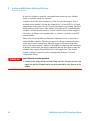
Individual cylinders
WA R N I N G
CO2 cylinders can be dangerous if handled improperly
➔ Carbon dioxide in cylinders is partially liquefied under high pressure and contains a
great deal of energy. If containment is breached (a break in the line or cylinder) the
entire contents will vaporize and quickly expand up to 500 times in volume and
create very forceful high velocity gas streams. Cylinders must be properly
constrained, and proper tubing used, to avoid damage that could generate
projectiles.
Any industrial grade of carbon dioxide is acceptable provided it is supplied in
a cylinder without a DIP tube. Drawing off the vapor phase leaves non-volatile
contaminants behind in the cylinder. Using cylinders with a DIP tube subjects
the chromatograph to contaminants soluble in the dense, liquid layer.
Larger tanks are more convenient in that they require to be changed less
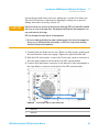
frequently. Cylinders can contain up to 35 kg of CO2. Generally, 4.6 mm
columns are run at 3 – 5 mL/min, which is approximately 2.5 – 4 g/min of
carbon dioxide. This is equivalent to 150 – 250 g/h; 1.2 – 6 kg/day. Thus, a
15 kg cylinder should last 2.2 to 11 days; a 25 kg cylinder would last 4 to 19
days; and a 35 kg cylinder could last 5.3 to 27 days - all depending on use (3 –
5 mL/min; 8 – 24 h/day). For individual users, particularly new users, the use
of cylinders is perfectly acceptable. Larger groups should consider installing a
gas delivery system and a bulk storage tank.
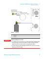
Locate the cylinder as close to the instrument as possible. In the past, the
cylinders were stored at much higher temperature than the lab temperature,
which resulted in vaporization in the supply line coming into the lab. Most
SFC pumps cannot condense this vapor and therefore, cannot deliver CO2.
Agilent 1260 Infinity SFC Control Module has a very powerful condenser
designed to accept vapor phase CO2. Nevertheless, it is always advisable to not
stress any equipment.
Facilities and safety personnel often wish to store and mount the cylinders
outside the lab — sometimes quite far from the intended location of the
instrument. They should recognize that the transfer lines can hold large
volumes, equivalent to a large fraction of a cylinder, particularly if tubing with
large ID is used. Shut-off valves at both ends of a transfer line are not
recommended, unless one or both has a pressure relief valve or burst disk.
1260 Infinity Analytical SFC System User Manual
55
3
Installing the G4309A Agilent 1260 Infinity SFC System
Hardware Installation
Be sure the cylinder is properly constrained and cannot tip over. Suitable
chains or cylinder straps are required.
Cylinders in the USA and Canada use a CGA 320 cylinder adapter. One is
included in the module USA ship kit, along with a 1/4 inch FNPT to 1/8 inch
compression fitting, and 6 feet of 1/8 inch OD stainless steel tubing. The filter
fitting sticking out the back of the Agilent 1260 Infinity SFC Control Module
contains 1/8 inch nut and ferrule(s), which could be used with the supplied
6 feet tube, or a longer, user-supplied tube, to connect a cylinder to the SFC
control module.
There are at least four different European standards for the connection of
carbon dioxide cylinders. They do not appear to change at national borders
(some users in one country have different supply connections from other
users in the same country). Agilent Technologies recommends that customers
in Europe contact their gas supply companies and ask them how to mate the
cylinders they supply with an American 1/8 OD supply line. This should
require a cylinder connector and a reducing union down to a 1/8 inch
compression fitting.
WA R N I N G
Leaks will not be sensed or protected
➔ Carefully check supply cylinders and inlet fittings for leaks. Any leaks present in the
supply line and inlet fitting will not be sensed or protected by safety features in the
module.
56
1260 Infinity Analytical SFC System User Manual
Installing the G4309A Agilent 1260 Infinity SFC System
Hardware Installation
3
8<6('%l^i]<Vh`Zi
Cdgi6bZg^XVdcan#
8djcignheZX^[^XVYVeeiZgcdi^cXajYZY#
8DHjeeana^cZ6hhZbWan
'
&$-^cX]
HlVY\ZadX`
Figure 21
WA R N I N G
Figure 3.25
O
Power off
I
Power on
Improper plumbing can cause leaks
➔ It is imperative to use two wrenches to install the supply fitting in the bulkhead filter
(entry connection) on the back of the module. Turning or twisting the bulkhead
supply filter could cause failures or leaks in tubing within the module.
➔ All supply fittings need to be thoroughly checked for leaks. Any leaks in the supply
fittings can vent the CO2 supply.
1260 Infinity Analytical SFC System User Manual
57
3
Installing the G4309A Agilent 1260 Infinity SFC System
Hardware Installation
CAUTION
Overtightening the fitting could damage the filter
➔ Use two wrenches when installing the CO2 supply line to the bulkhead filter (entry
connection) on the back of the module. Although the filter is captured and should
not rotate, there is a remote possibility that fittings inside the module could be
loosened by severe stress on the nut on the supply line. Leakage inside the cabinet
requires service by trained personnel.
Gas Delivery Systems (GDS)
Anyone performing semi-prep SFC has probably been convinced that
operation without a GDS is problematic. Thus, many laboratories are now
plumbed with carbon dioxide boosted to 70 – 80 bar outlet pressure. Even
though an analytical system does not need such a GDS, it is perfectly adapted
to its use.
The Agilent 1260 Infinity SFC Control Module has an inlet safety shut-off valve
rated to 1500 psi (>100 bar). While this is rating is well above the outlet
pressure of any typical GDS, past experience suggests that it is wise to allow
for some extra margin. Agilent Technologies suggests setting the local output
of any GDS between 60 bar and 70 bar, through local outlet pressure
regulators.
Under these conditions, the GDS will almost always provide liquid carbon
dioxide to the chromatograph. Unlike some earlier systems, the Agilent 1260
Infinity SFC Control Module easily condenses any fluid that is present as a
vapor, and prevent pump cavitations.
Cable connections to the HPLC
WA R N I N G
Personal injury
➔ Ensure that the AC power cord is NOT yet connected to the instrument.
Cable connections to the Agilent 1260 Infinity SFC Control Module are
dependent upon the installed configuration. The primary decision to be made
is whether or not an Agilent autosampler is present. When an Agilent 1260
Infinity SFC Autosampler is present, the Agilent 1260 Infinity SFC Control
Module remote line and relay contacts lines are connected to the autosampler.
58
1260 Infinity Analytical SFC System User Manual
Installing the G4309A Agilent 1260 Infinity SFC System
Hardware Installation
3
The Binary pump analog output signal should be connected to the Agilent
1260 Infinity SFC Control Module Reference in terminal.
GZ[ZgZcXZh^\cVa
GZbdiZh^\cVa
GZaVnh^\cVa
Figure 22
Reference, Remote and Relay Signal Connections
O
Power off
I
Power on
Lastly, a cable should be connected to the Agilent 1260 Infinity SFC Control
Module USB port. This can be run to any convenient, compatible USB port on
the PC.
CAN cabling between the Agilent 1260 Infinity modules is unchanged from the
normal, recommended means of interconnecting HPLC devices.
1260 Infinity Analytical SFC System User Manual
59
3
Installing the G4309A Agilent 1260 Infinity SFC System
Hardware Installation
The Agilent 1260 infinity stack requires a LAN connection to the PC. This LAN
connection requires all the normal HPLC/ChemStation properties such as
BOOTP, Firewall, and IP Address settings. These remain unchanged in an
Agilent 1260 Infinity SFC Control Module installation.
Connecting and operating multiple instruments on a single PC is not
supported. Both the Agilent 1260 Infinity SFC Control Module USB and
Agilent 1260 Infinity LAN connections must be made on the PC on which
ChemStation is installed and which is used for instrument control.
60
1260 Infinity Analytical SFC System User Manual
Installing the G4309A Agilent 1260 Infinity SFC System
Hardware Installation
3
Connecting the Leak Tray Waste Line
The Agilent 1260 Infinity SFC Control Module contains a leak tray on the
bottom of the instrument to collect and sense any liquid spills that may occur
in the Agilent 1260 Infinity SFC Control Module cabinet. In the bottom of this
leak tray is an active sensor that continuously monitors for the presence of
liquid.
The drip tray contains an overflow drain to divert any large amounts of
collected liquid to an external collection container. The overflow tube
incorporates a simple push-to-connect fitting. It is connected to the port on
the bottom center on the front of the instrument. Pushing on the outside ring
of the port allows this line to be removed.
Since this liquid may be organic solvents, you should supply an appropriate
collection container.
AZV`igVnlVhiZa^cZ
,$&+In\dc*$&+>9
Figure 23
Leak Tray Waste Line
1260 Infinity Analytical SFC System User Manual
61
3
Installing the G4309A Agilent 1260 Infinity SFC System
Hardware Installation
Preparing the HPLC
Preferred Stack Arrangement
To minimize delays and broadening caused by excessive tube lengths, we
recommend the following stack layout. The Agilent 1260 Infinity SFC Control
Module needs to be immediately adjacent to the LC stack, but can be placed on
either side. In the preferred arrangement, the degasser and solvent tray are
located on the top of the stack. These feed into the binary pump, and the SFC
control module injection wash pump. The binary pump is located below the
degasser and directly above the autosampler. The thermostatted column
compartment is located below the autosampler, with the detector at the
bottom of the stack.
9Z\VhhZg
7^cVgnH;8Ejbe
H;86jidhVbeaZg
I]ZgbdhiViiZYXdajbcXdbeVgibZci
969dgBL9
Figure 24
62
Preferred order of Agilent HPLC Components
1260 Infinity Analytical SFC System User Manual
Installing the G4309A Agilent 1260 Infinity SFC System
Hardware Installation
3
It is recommended to plumb the system with small diameter tubing. For
general use 0.17 mm or 0.007 inch tubing should be used. In more demanding
applications where pressure drops are not excessive, 0.12 mm or 0.005 inch
tubing can be selectively used. Use ferrules and tubing connections as
recommended by the equipment manufacturer.
All four degasser channels will be available for solvent usage. It is highly
recommended that one channel be reserved for neat methanol (no additives).
Reserving this channel will minimize the time needed for flushing the degasser
as solvents are changed. Failure to adequately flush the degasser when
switching solvents will greatly impact sensitivity.
Agilent 1260 Infinity SFC Binary Pump
It is highly recommended that you familiarize yourself with standard
maintenance functions and terminology used in the binary pump. This
information is available in the Agilent Binary pump reference manual and
user guide.
9VbeZgl^i]Wj^aY^cEgZhhjgZHZchdg!egZhhjgZa^b^i+%%WVg!VcY8a^e[dgb^mZg
8Ve^aVgnEK
KVakZ=daYZg
KVakZ]daYZg[dgi]^gYD7K
8Ve^aaVgn
6YVeiZgbVaZ$[ZbVaZ
8d^aZY8Ve^aaVgn
Figure 25
Diagram of the Agilent Binary Pump
The G4303A SFC Pump is a binary high pressure mixing pump, optimized for
the usage in a SFC System. The Purge Valve is mounted on the right side for
purging the Modifier Channel (Channel B) only. An additional third Outlet
1260 Infinity Analytical SFC System User Manual
63
3
Installing the G4309A Agilent 1260 Infinity SFC System
Hardware Installation
Ball Valve (OBV) is installed with a Valve Holder on Pumphead B, to allow the
Channel B to be flushed, even if CO2 tank pressure is supplied to the System.
On the Passive Inlet valve of the CO2 Channel (Channel A) is an Adapter to
allow a Swagelok fitting to be connected to the valve. The damper includes the
pump pressure sensor and allows a pressure up to 600 bar. Different set of
piston seals are installed in the two pump heads. Normal phase seals (yellow
PE) in pump head channel A, standard seals PTFE, carbon filled in pump head
channel AB.
WA R N I N G
Toxic, flammable and hazardous solvents, samples and reagents
The handling of solvents, samples and reagents can hold health and safety risks.
➔ When working with these substances observe appropriate safety procedures (for
example by wearing goggles, safety gloves and protective clothing) as described in
the material handling and safety data sheet supplied by the vendor, and follow good
laboratory practice.
➔ The volume of substances should be reduced to the minimum required for the
analysis.
➔ Do not operate the instrument in an explosive atmosphere.
The BNC coaxial cable can be used to connect the Analog Output on the back
panel of the Binary pump to the Agilent 1260 Infinity SFC Control Module
Reference In terminal/connector on the back of the SFC control module. Be
aware that the output of similar appearance on the DAD and VWD detectors
should NOT be used.
64
1260 Infinity Analytical SFC System User Manual
Installing the G4309A Agilent 1260 Infinity SFC System
Hardware Installation
3
GZVgd[H;87^cEjbe
Figure 26
Connecting the Analog Reference Signal
O
Power off
I
Power on
1260 Infinity Analytical SFC System User Manual
65
3
Installing the G4309A Agilent 1260 Infinity SFC System
Hardware Installation
Modifications to the Agilent Autosampler
KVakZ7dYn
>hdaVi^dcHZVaHeg^c\id7VX`
6jgdgV(<gddkZGdidgHZVa
HiVidg=ZVY
.$+)]ZmhXgZlh
Figure 27
NOTE
66
Exploded View of the Autosampler Injection Valve
Replacing a rotor seal is well documented in Agilent manuals, and service videos. Please
refer to these guides for further assistance.
1260 Infinity Analytical SFC System User Manual
3
Installing the G4309A Agilent 1260 Infinity SFC System
Hardware Installation
1 The Autosampler should be plumbed in accordance with Figure 28 on
page 67.
BZiZg^c\9Zk^XZ
CZZYaZ
[gdbejbe
CZZYaZHZVi
8]ZX`KVakZ
8dciV^cZYLVhiZ
idXdajbc
Figure 28
Autosampler Fluidic connections
2 Connect one end of the wash pump transfer line with the check valve to the
outlet port of the injection wash pump.
3 Before connecting the union end of the wash pump transfer line, use a
syringe and Luer Adapter to prime (pull sample through) the injection wash
pump
4 The existing line (blue capillary) from the inlet of the Agilent 1260 Infinity
SFC Autosampler metering device can be plumbed into the union on the
wash pump transfer line
1260 Infinity Analytical SFC System User Manual
67
3
Installing the G4309A Agilent 1260 Infinity SFC System
Hardware Installation
Positioning the waste line
In normal operation, the sample loop is switched from mainpass i(n the high
pressure flow stream) to bypass (out of the flow stream and connected to the
seat capillary and waste). As the valve switches, the fluid in the loop expands
and rushes out of the loop through the waste line. If the waste line is
positioned to empty into a liquid reservoir such as a WPA flush port, the
exiting fluid from the sample loop could splash the flush port fluid across the
ALS. The preferred positioning of the waste line is through the leak vent. In
this position, the expanding fluid exits harmlessly into the leak tubing.
Alternatively, a waste line can be fabricated that empties into the Agilent 1260
Infinity SFC Control Module gas liquid separator (waste bottle).
Under no circumstances should the waste line be allowed to be unconstrained.
During operation of the injection wash pump, this is the final exit of the wash
fluid.
Installing the Agilent BCD Board
The BCD Interface card ( Interface board (BCD) with external contacts and
BCD outputs (G1351-68701)) and relay cable from the shipping kit are used to
control the wash pump.
789>ciZg[VXZXVgY
Figure 29
BCD Interface Card
Agilent HPLC autosamplers have a small compartment located on the back
panel near the top, with a cover held in place by two captured knurled nuts.
68
1260 Infinity Analytical SFC System User Manual
3
Installing the G4309A Agilent 1260 Infinity SFC System
Hardware Installation
Loosen the nuts and remove the cover, taking care to retain it for future use.
Take the BCD Interface card from the shipping kit, taking care to prevent
damage from static electricity, solvent, etc.
CAUTION
Electronic boards are sensitive to electrostatic discharge (ESD) and should be handled
with care so as not to damage them. Touching electronic boards and components can
cause electrostatic discharge.
ESD can damage electronic boards and components.
➔ Be sure to hold the board by the edges and do not touch the electrical components.
Always use an ESD protection (for example, an ESD wrist strap) when handling
electronic boards and components.
1 Carefully slide the board into the slot. When it is fully in place, gently push
the bezel until the connectors engage. Tighten the captive knurled nuts.
2 With the BCD card in place, connect the 15-pin relay contacts connector to
the relay input connector on the back of the SFC control module.
3 Connect the 9-pin Remote connector on the back left of the autosampler to
the 9-pin Remote connector on the back of the SFC control module.
Figure 30
Autosampler Signal Cable Connections
O
Power off
I
Power on
1260 Infinity Analytical SFC System User Manual
69
3
Installing the G4309A Agilent 1260 Infinity SFC System
Hardware Installation
Installing an Injection Program in the Method
The injector program is delivered as part of the default setup, but you can
enter it manually, if necessary.
Table 14
Agilent 1260 Infinity SFC Autosampler Injector Program
Injection
Injection Volume
15.0 µL
Injection Mode
Injector Program
Time
Stoptime
No Limit
Posttime
Off
High Throughput
Autom. Delay Vol. Reduction
Off
Overlapped Injection
disabled
Minimized Carry Over
Off
Needle Wash
Wash Mode
Wash in Flushport
Wash Time
1.0 s
Wash Location
Vial 10
Repeat
1 times
Injector Cleaning
Injection Valve Cleaning / Valve Switching
Time 1 Bypass
off
Time 2 Mainpass/Bypass
off
Time 3 Mainpass/Bypass
off
Time 4 Mainpass/Bypass
off
Valve Movements
1
Auxiliary
70
Draw Speed
100 µL/min
Eject Speed
100 µL/min
Draw Position
0.0 mm
1260 Infinity Analytical SFC System User Manual
Installing the G4309A Agilent 1260 Infinity SFC System
Hardware Installation
Table 14
3
Agilent 1260 Infinity SFC Autosampler Injector Program
Equilibration Time
2.0 s
Sample Flush-Out Factor
5.0 times Injection Volume
Vial/Well Bottom Sensing
No
Store Temperature
No
Injector program table
Row
Action
1
NEEDLE down
2
CONTACT B CLOSED
3
WAIT 0.10 min
4
CONTACT B OPEN
5
VALVE bypass
6
DRAW 1.5 µL from air, def. speed
7
DRAW def. amount from sample, def. speed,
def. offset
8
DRAW 5 µL from air, def. speed
9
NEEDLE wash as method
10
EJECT max. amount into seat, def. speed
11
VALVE mainpass + start pulse
12
CONTACT B CLOSED
13
WAIT 0.10 min
14
CONTACT B OPEN
Agilent Contacts Option
NOTE
Contact 1
Open
Contact 2
Open
Contact 3
Open
Contact 4
Open
Using the Agilent SFC Autosampler as a fixed loop to (external) loop autosampler has
several minor consequences that need to be understood to achieve adequate performance.
1260 Infinity Analytical SFC System User Manual
71
3
Installing the G4309A Agilent 1260 Infinity SFC System
Hardware Installation
Dead Volume-Partial Loop Injections
Plumbed as a loop injector, the Agilent 1260 Infinity SFC Autosampler has a
dead volume between the high pressure needle seat and the groove on the
rotor of the injection valve. Two different diameter tubes are used to make this
connection. Thus, the actual dead volume can have several different values,
depending on the ID of the tubing that is used. This dead volume can be
several micro liters or more. When attempting to make low-volume injections,
it may be possible that no sample enters the loop unless precautions are taken.
Use an air bubble on each side of the sample, insert a plug of modifier or other
solvent behind the sample, or any other method to ensure that the sample
reaches the loop.
L^i]YgVl
Gjc
&
'
LVhiZ
LVhiZ
CZZYaZ
CZZYaZ
AdVY
8dajbc
Ejbe
8dajbc
Ejbe
(
>c_ZXi"GdiViZ
)
LVhiZ
LVhiZ
lVh
'#*"'#* μ A
* μA
8dajbc
*
8dajbc
gdiViZkVakZ
Figure 31
72
Ejbe
Ejbe
Full Loop Injection
1260 Infinity Analytical SFC System User Manual
3
Installing the G4309A Agilent 1260 Infinity SFC System
Hardware Installation
9gVlV^gWjWWaZ
9gVl'cYV^gWjWWaZ
CZZYaZ
CZZYaZ
LVhiZ
LVhiZ
8dajbc
8dajbc
Ejbe
CZZYaZ
LVhiZ
8dajbc
Figure 32
CZZYaZ
Ejbe
8dajbc
Ejbe
LVhiZ
CZZYaZ
Ejbe
LVhiZ
8dajbc
Ejbe
Partial Loop Injection
Some General Injection Rules
20 μL loops are commonly used in HPLC. In SFC, the sample is often dissolved
in a solvent that is stronger than the mobile phase. Injecting large volumes,
such as 20 μL, of such a solvent will cause peak distortion.
As a rule of thumb, no more than approximately 5 μL of a polar solvent such
as methanol should be injected onto a 4.6 mm ID column, as shown in
Figure 33 on page 74.
This should NOT have a major impact on area reproducibility but should
destroy efficiency as indicated in Figure 33 on page 74.
1260 Infinity Analytical SFC System User Manual
73
3
Installing the G4309A Agilent 1260 Infinity SFC System
Hardware Installation
Use Small Loops
The loop should not be much larger than the maximum desired injection (or
=<5 μL). Bear in mind that the loop is washed with a strong solvent, and is
usually filled with that solvent. The sample displaces some or all of this
solvent.
b6J
If the loop is too large, too much strong solvent is injected, regardless of
whether the loop is filled with sample or wash solvent. Peaks will be distorted
and efficiency will degrade.
>c_ZXi^dcKdajbZ
Figure 33
Plot showing loss of efficiency with large injection volume
If a large loop is used, air bubbles can be used to displace the wash solvent.
Less Polar Sample Solvents Help
Replacing the sample solvent with a much less polar solvent can allow
injection of much larger volumes. However, the new solvent must be
significantly less polar than the modifier used. Replacing methanol with
ethanol or even isopropanol has minimal effect. Solvents such as chloroform
or methylene chloride tend to cause significant focusing (NO broadening), but
since they are chlorinated should probably be avoided.
74
1260 Infinity Analytical SFC System User Manual
3
Installing the G4309A Agilent 1260 Infinity SFC System
Software Installation
Software Installation
The software installation consists of the following steps:
1 Install Agilent ChemStation, for more details see Agilent ChemStation for
LC and CE Systems Installation Manual, Chapter Installing the Agilent
ChemStation, Initial Installation.
2 Install SFC USB driver.
3 Install the Driver Software, see “Installing Agilent 1260 Infinity SFC
Control Module Driver Software” on page 75
Installing Agilent 1260 Infinity SFC Control Module Driver Software
The driver is installed as an add-on product for ChemStation.
The following screenshots show the installation steps. It is important to select
the ChemStation installation directory as destination path!
1 Start the Sfc Fusion ChemStation Interface Setup Wizard
1260 Infinity Analytical SFC System User Manual
75
3
Installing the G4309A Agilent 1260 Infinity SFC System
Software Installation
2 Select installation folder.
3 Confirm installation.
76
1260 Infinity Analytical SFC System User Manual
Installing the G4309A Agilent 1260 Infinity SFC System
Software Installation
3
4 Install the Sfc Fusin ChemStation Interface.
5 Complete the installation.
1260 Infinity Analytical SFC System User Manual
77
3
78
Installing the G4309A Agilent 1260 Infinity SFC System
Software Installation
1260 Infinity Analytical SFC System User Manual
1260 Infinity Analytical SFC System User Manual
4
Configuring the System
Configuring SFC interface in ChemStation
Setting up the Method
Status
Control
80
84
86
87
Testing the System
88
How to configure the Agilent 1260 Infinity SFC Analytical system and Agilent
1260 Infinity SFC Control Module in ChemStation.
Agilent Technologies
79
4
Configuring the System
Configuring SFC interface in ChemStation
Configuring SFC interface in ChemStation
NOTE
The Agilent 1260 Infinity SFC Control Module ChemStation interface works with the
ChemStation Modular LC System, not with Modular LC System (Classic). The Modular LC
System (Classic) instrument does not support RC.Net drivers, which are necessary for the
LC modules.
1 Select Modular LC System as instrument type.
2 Start the Agilent ChemStation.
3 Configure the devices in the Agilent ChemStation, see Agilent ChemStation
for LC and CE Systems Installation Manual, Chapter Configuring the
Instruments, Configuring a Modular 3D LC System or Modular LC System.
80
1260 Infinity Analytical SFC System User Manual
Configuring the System
Configuring SFC interface in ChemStation
4
4 Depending on the current configuration, Agilent ChemStation startup
phase asks if the configuration shall be modified.
5 In the Instrument Configuration editor Auto Configuration sets up the Agilent
system as usual.
CAUTION
Conflict with SFC macro implementation
➔ It is important that the SFC Control Module is listed below the Agilent pump;
otherwise, the SFC will become pump 1 of the system, which conflicts with the
current SFC macro implementation. The SFC macro always checks the first pump of
the system for error or standby.
1260 Infinity Analytical SFC System User Manual
81
4
Configuring the System
Configuring SFC interface in ChemStation
6 To set up the SFC module, scroll down the Configurable Modules slider until
you see the SFC icon. Select it with a double-click or right arrow to move it
to the Selected Modules panel.
7 Select Configure to open the SFC configuration dialog box.
82
1260 Infinity Analytical SFC System User Manual
4
Configuring the System
Configuring SFC interface in ChemStation
8 In the Aurora SFC Configuration, enter the device name or use the default to
identify the module within Agilent ChemStation. Select a COM Port in the
Aurora COM Port field.
9 Press OK to accept the settings.
10 Click OK in the Agilent ChemStation Instrument Configuration to apply all
configurations.
1260 Infinity Analytical SFC System User Manual
83
4
Configuring the System
Setting up the Method
Setting up the Method
1 In the Agilent ChemStation, the method parameters for all RC.Net devices,
including SFC settings, are combined into a single tabbed dialog box:
84
1260 Infinity Analytical SFC System User Manual
Configuring the System
Setting up the Method
4
2 The Instrument Curves tab shows all instrument curves (monitor traces)
available for storing with the acquired data file:
1260 Infinity Analytical SFC System User Manual
85
4
Configuring the System
Status
Status
1 To start Aurora SFC Status in Agilent ChemStation go to View > Instrument
Actuals. The Instrument Actuals have to be enabled.
2 The available status information depends on the configuration (e.g. Aux
Pressure).
3 The button in the upper left corner of the Status user interface allows you to
either switch the device ON or put it into Standby mode.
86
1260 Infinity Analytical SFC System User Manual
Configuring the System
Control
4
Control
The following steps show you how you can control your SFC instrument in the
Agilent ChemStation.
1 In Instrument > More SFC you find more menu items that allow you to control
the device directly.
2 To change the status of the SFC device and to Depressurize, go to Instrument
> More SFC > Control. This displays the Aurora SFC Control dialog box.
1260 Infinity Analytical SFC System User Manual
87
4
Configuring the System
Testing the System
Testing the System
The SFC driver lists all available configuration, method and status values in
ChemStation registers, available by macros.
Additionally, it works with the ChemStation
SendModule$-function. Using this command, you can send commands
directly to the SFC module. There are special commands, allowing you to
enable and disable diagnostic mode (
print SendModule$(SFC1, EnableDiag) /
print SendModule $(SFC1, DisableDiag).
Enabling Diagnostic immediately shows additional status information in the
Status window. Additionally, a separate configuration menu item shows up in
Instrument > More, and Additional instrument curves are available in the Online
plot.
NOTE
88
Enabling Diagnostic mode requires a restart of Agilent ChemStation, to show the
Additional configuration item and Instrument curves.
1260 Infinity Analytical SFC System User Manual
1260 Infinity Analytical SFC System User Manual
5
Using the Agilent 1260 Infinity SFC
Control Module
Powering up the Module
90
Power-up Sequence and Operational Control States
91
Operational Control States 92
The OFF State 93
The STANDBY State 93
The ON State 94
Controlling the Agilent 1260 Infinity SFC Control Module through the
Agilent ChemStation 95
Running a method on the SFC system
Shutting Down the SFC System
Partial Shutdown 101
98
101
This chapter provides information and hints on the use of the SFC System.
Agilent Technologies
89
5
Using the Agilent 1260 Infinity SFC Control Module
Powering up the Module
Powering up the Module
The Agilent 1260 Infinity SFC Control Module is powered on by pressing the
top of the rocker-type power switch located on the upper right rear of the
module. Once the rocker is pressed, the module responds by entering its
power-up sequence. The power button of the module must remain accessible at
all times. Never arrange equipment so that the switch cannot be accessed.
WA R N I N G
The power switch has to be reachable for emergency
➔ The power switch of the module must remain accessible at all times. Never arrange
equipment so that the switch cannot be accessed.
90
1260 Infinity Analytical SFC System User Manual
5
Using the Agilent 1260 Infinity SFC Control Module
Power-up Sequence and Operational Control States
Power-up Sequence and Operational Control States
When power is applied to the Agilent 1260 Infinity SFC Control Module, a
series of events is initiated. The order of these events is designed to safely
initialize and test individual component functionality. The module power-up
sequence executes the following steps:
1 Power is automatically applied to the processor and the two module fans.
2 The processor initializes:
a Any temporary configuration or calibration data that has not been
stored in flash memory is lost.
b A checksum validation is made of data stored in flash memory.
c A self test is run to test power supply voltage levels and sensor readings
for in-range values
d Stored calibration and configuration data are downloaded to RAM.
e The event logbook is updated
3 The booster pump drive is rotated to find its index pulse.
4 Index pulses are tested for module fans and the coolant pump.
5 The BPR is homed to its fully open (depressurized) position.
6 If installed, the wash pump is rotated to its index pulse.
At the completion of a successful power-up sequence, the processor places the
module in the OFF operational state, described in “Operational Control
States” on page 92. If an error is encountered and unresolved after multiple
attempts, the module is placed into the ERROR state and a notation is stored
in the event log.
1260 Infinity Analytical SFC System User Manual
91
5
Using the Agilent 1260 Infinity SFC Control Module
Operational Control States
Operational Control States
The Agilent 1260 Infinity SFC Control Module has three defined operational
control states: OFF, STANDBY and ON. You control the three states by
selecting the Control option from either the ChemStation SFC Fusion icon, by
pressing various icons of the ChemStation GUI, or from the Aurora A5
Diagnostic Program status tab.
Some components of the Agilent 1260 Infinity SFC Control Module are not
governed by the three described states but are continuously on. These include:
✔ The processor.
• Continuously records and transmits sensor data to the host control
system.
• Handles status and command requests from the host controller.
• Monitors sensors for safety-related parameters.
• Updates the event log.
✔ Pressure and temperature sensors are continuously powered and sensed.
✔ Coolant and electronics bay fans are continuously powered.
✔ The wash pump is activated by contact closure of the external contacted
board placed in the SFC Autosampler, independent of the Agilent 1260
Infinity SFC Control Module control state.
92
1260 Infinity Analytical SFC System User Manual
Using the Agilent 1260 Infinity SFC Control Module
Operational Control States
5
The OFF State
The OFF state is characterized as follows:
✔ The CO2 supply valve is closed (unpowered).
✔ The booster pump drive is unpowered.
✔ The BRP drive is unpowered.
✔ The BRP heater is unpowered.
✔ The chiller is unpowered.
✔ The secondary cooling circuit pump is unpowered.
The OFF state is always entered after a successful power-up sequence. It can
also be entered by selecting the Off option in the control window, by a timeout
from the STANDBY state or by pressing Off in the Agilent ChemStation
graphical user interface twice in succession.
When the Agilent 1260 Infinity Control Module is in the OFF state, the top
“power” status light is constant and the bottom “ready” status light is off.
The STANDBY State
The STANDBY state is characterized as follows:
✔ The CO2 supply valve is closed (unpowered).
✔ The booster pump drive is unpowered.
✔ The BRP drive is powered.
✔ The BRP heater is powered.
✔ The chiller is powered.
✔ The secondary cooling circuit pump is powered.
The STANDBY state can also be entered by selecting the Standby option in the
control window, by pressing the power button associated with the SFC icon of
the GUI, or by pressing Off in the ChemStation graphical user interface once
while the system is running.
When the STANDBY state is entered from the OFF state, the BPR must be
homed. Once this is accomplished, the BPR drive is active but in a hold state.
1260 Infinity Analytical SFC System User Manual
93
5
Using the Agilent 1260 Infinity SFC Control Module
Operational Control States
When the Agilent 1260 Infinity SFC Control Module is in the STANDBY state,
the two status lights flash alternately. The STANDBY state remains active for up
to three hours. If no user-initiated action is taken to change or renew the state
within this time, a timeout occurs and the processor automatically enters the
OFF state.
The ON State
The ON state is characterized as follows:
✔ The CO2 supply valve is open (powered).
✔ The booster pump drive is powered and begins to pump CO2 to the pressure
target.
✔ The BRP drive is powered and the BRP begins the process of regulating to
its setpoint.
✔ The BRP heater is powered.
✔ The chiller is powered.
✔ The secondary cooling circuit pump is powered.
The ON state can also be entered by selecting the On option in the control
window, by pressing the power button associated with the SFC icon of the
GUI, or by pressing On in the ChemStation graphical user interface.
When the Agilent 1260 Infinity SFC Control Module is in the ON state, the top
status light is continuously lit. The bottom status light is lit when the system
reaches a “ready” state, indicating that backpressure and booster pump
pressure are under control and stabilized within their control band.
Modules that start from the OFF state generally must first perform an
initialization routine before moving to ON. In the case of the Agilent 1260
Infinity SFC Control Module, initialization causes the BPR first to home, then
move to a default initialization position. The booster pump delays operation
until the chiller passes below a threshold temperature value.
94
1260 Infinity Analytical SFC System User Manual
Using the Agilent 1260 Infinity SFC Control Module
Controlling the Agilent 1260 Infinity SFC Control Module through the Agilent ChemStation
5
Controlling the Agilent 1260 Infinity SFC Control Module through
the Agilent ChemStation
Exploring the module Graphical User Interface (GUI)
Figure 34
Setting Control State
1260 Infinity Analytical SFC System User Manual
95
5
Using the Agilent 1260 Infinity SFC Control Module
Controlling the Agilent 1260 Infinity SFC Control Module through the Agilent ChemStation
Figure 35
Editing the SFC control module Method Parameters
Editable method parameters for the Agilent 1260 Infinity SFC Control Module
are the Nozzle Pressure (system back-pressure) and the Nozzle Temperature
(temperature of the back-pressure regulator).
96
1260 Infinity Analytical SFC System User Manual
Using the Agilent 1260 Infinity SFC Control Module
Controlling the Agilent 1260 Infinity SFC Control Module through the Agilent ChemStation
5
Controlling the wash pump
When the wash pump icon is clicked, the wash pump starts pumping for 30
seconds and flushes the autosampler metering, loop, needle and needle seat
with solvent, Typically, modifier solvent is used to flush the autosampler. The
wash pump is controlled by the Agilent SFC autosampler via the built-in BCD
board, and works independently of the current state of the Agilent 1260
Infinity SFC Control Module.
1260 Infinity Analytical SFC System User Manual
97
5
Using the Agilent 1260 Infinity SFC Control Module
Running a method on the SFC system
Running a method on the SFC system
Loading the SFC_Def analysis method
When the SFC Driver add-on for ChemStation is installed, the method
SFC_Def.M is copied to the default method folder. This method contains
parameters most commonly used in SFC. You should develop your SFC
methods from this default method.
SFC_DEF.M contains an injector program for full loop injection.
98
1260 Infinity Analytical SFC System User Manual
Using the Agilent 1260 Infinity SFC Control Module
Running a method on the SFC system
5
Adjusting the method for use
The Injector timetable includes an additional flush of the Autosampler for
0.1 min by the wash pump. By default, the injection volume is 15 μL, which
corresponds to an overfill of the sample loop by approximately three times.
Default Pump setting is 80 % CO2 : 20 % modifier. Typical Flow rate in SFC is
3 mL/min; however, when
SFC_DEF.M is loaded, the flow rate is set to 0 mL/min. Solvent compressibility
should be always set to no compensation for the CO2 Channel, and to the
corresponding value for the modifier.
1260 Infinity Analytical SFC System User Manual
99
5
100
Using the Agilent 1260 Infinity SFC Control Module
Running a method on the SFC system
1260 Infinity Analytical SFC System User Manual
5
Using the Agilent 1260 Infinity SFC Control Module
Shutting Down the SFC System
Shutting Down the SFC System
The manner of shutting down the SFC depends on the requirement for rapid
equilibration of the system on the next startup, and the duration of the
shutdown. If the system will be shut down for some time, it is probably best to
shut down all components including the DAD and column oven. These
components tend to take longer to reach their stable operating conditions than
the other components in the system. You should always shut down both the
SFC control module and the binary pump if the system is to be idle for a long
time.
Partial Shutdown
WA R N I N G
Injuries from pressurized CO2
➔ Setting the pump to STANDBY does not depressurize the system. Do not attempt to
loosen fittings or perform maintenance under these conditions. Serious skin and
eye injuries can occur as the result of sudden release of CO2 in the liquid or
supercritical state. Always wear gloves and eye protection when maintaining the
module.
1260 Infinity Analytical SFC System User Manual
101
5
Using the Agilent 1260 Infinity SFC Control Module
Shutting Down the SFC System
Leaving the system pressurized
If the system is to be shut down for less than two hours, a partial pressurized
shutdown is recommended. Press the control buttons (for example, button 2) to
switch the Agilent 1260 Infinity SFC Control Module and binary pump states
to STANDBY. In this case, the system remains pressurized, and slowly bleeds
pressure through the nozzle. A residual pressure remains in the system when
the nozzle closes fully at lower pressure. The booster remains chilled, and
much of the startup CO2 is preserved. You should be aware that the system is
pressurized and not to attempt maintenance under these conditions.
The detector and column oven are left in the ON state, to maintain their
readiness. You may elect to exit the ChemStation in this state, and should
answer NO to the “Shutdown Lamps…” query that appears during shutdown.
Restarting the ChemStation brings the system to this same state. If more than
two hours elapse in STANDBY mode, the Agilent 1260 Infinity SFC Control
Module enters the OFF state, and pressure may be lost at a more rapid rate.
102
1260 Infinity Analytical SFC System User Manual
5
Using the Agilent 1260 Infinity SFC Control Module
Shutting Down the SFC System
Depressurizing the system
When maintenance is required on the SFC system, such as replacing the
column, the system should be depressurized. It is not necessary to shut down
all modules, but only the pumps and any other devices undergoing
maintenance. To depressurize the system, stop the Agilent 1260 Infinity SFC
Control Module and the binary pump. In the Control… menu of the Agilent 1260
Infinity SFC Control Module booster (the standby state will be selected) check
the Depressurize box and click OK.
NOTE
If the Agilent 1260 Infinity SFC Control Module unit itself is to be serviced, select OFF in the
Control window. This shuts off the BPR heater and booster chiller and allows them to move
toward ambient temperature.
This causes the BPR to home and fully open the CO2 path to depressurize. The
Agilent 1260 Infinity SFC Control Module unit contains approximately 25 mL
of stored CO2. This amount of CO2 should be vented properly, which takes
several minutes. You should allow the system to drain below 40 bar before
cracking any fittings. At this point the, CO2 is in the vapor state, and
represents a small expanded volume. However, do not inhale vapor directly
from a cracked fitting. The concentration of CO2 emerging from a flow line,
even at low pressure, can be dangerous or even lethal.
WA R N I N G
Avoid inhaling high concentration of CO2
➔ Never inhale vapor issuing from an SFC flow line. Exposure to concentrations of CO2
over 5 % in air can be lethal. Always keep tubes directed away your face. CO2 is
ubiquitous in the atmosphere, but at high levels should be treated with the same
care as other toxic chemicals. Always wear gloves and eye protection for safety.
Avoid inhaling venting gas near open fittings.
Alternatively, if the column oven contains a column switching valve, one path
may be jumpered without a column. The reduced restriction will allow the
system to depressurize much faster. Further, the isolated column can be
exchanged immediately since the contained volume of CO2 is small.
1260 Infinity Analytical SFC System User Manual
103
5
Using the Agilent 1260 Infinity SFC Control Module
Shutting Down the SFC System
WA R N I N G
System contains always 25 ml liquid CO2 under pressure
➔ The Agilent 1260 Infinity SFC Control Module unit contains approximately 25 mL of
liquid CO2. The CO2 must be vented properly since the expanded volume will allow
local concentrations exceeding the OSHA PEL. Always allow the system to
depressurize to below 40 bar before cracking any fittings. Always keep fittings
directed away from the face.
104
1260 Infinity Analytical SFC System User Manual
1260 Infinity Analytical SFC System User Manual
6
Maintenance and Repair
Inspection and Preventative Maintenance Intervals
Daily Inspection and Maintenance 106
Every 3 months 107
As Needed (Corrective) 107
106
General Maintenance procedures 108
Booster Drawer 108
Replacing Fuses 115
Standard Decontamination 115
Plugged BPR Decontamination 116
Preparing for storage or shipping 117
In this chapter only the SFC specific procedures are described. For procedures
similar to the Agilent module procedures, please refer to the single module
manuals (G1312C, G1329B, G1316C, G1315/65C, G4225A)
Agilent Technologies
105
6
Maintenance and Repair
Inspection and Preventative Maintenance Intervals
Inspection and Preventative Maintenance Intervals
Inspection and maintenance of the Agilent 1260 Infinity Analytical SFC
System are critical elements of long term reliability and performance of the
system. Maintenance falls into two categories, preventative and corrective.
Preventative maintenance intervals can vary based on the system use. The
intervals offered in this section are for systems with average use of
approximately 30 hours per week. Infrequently used systems may extend
these intervals, while heavily used systems may require more frequent
preventative maintenance. Most service can be performed directly by the user
or in-house maintenance technicians.
Daily Inspection and Maintenance
✔ Verify that power and signal cables are firmly connected and not under
strain.
✔ Inspect all user-serviceable high pressure tubes and transfer lines for
crimping or very tight bends. Replace as necessary.
✔ Wipe up any visible liquid spills or condensation on or near the instrument.
✔ Verify that all covers are securely fastened to the frame.
✔ Inspect all reservoirs to ensure an adequate solvent supply.
✔ Prime the wash pump and modifier pumps. Check that the purge valve
reseals without leaking
✔ Empty all waste containers
✔ Check that the exhaust line is attached to a ventilation system, and that the
ventilation system is drawing.
✔ If an inlet step-down regulator is used with a gas supply system, check that
the inlet pressure is between 40 and 70 bar.
✔ Check the integrity of the SFC Flow path (that is, that column, flow cell etc
have not been removed).
✔ With the system running, visually inspect unions and tees for leaks. Run
diagnostic leak test for added sensitivity.
✔ Check CO2 air monitor, if available, for suitable exposure level [< 5000 ppm
CO2]
106
1260 Infinity Analytical SFC System User Manual
Maintenance and Repair
Inspection and Preventative Maintenance Intervals
6
Every 3 months
✔ Run nozzle diagnostic test.
✔ Run system leak test.
✔ Evaluate system calibration.
✔ Check chiller efficiency curve.
✔ If CO2 cylinders are used as supply, change the cylinder seal (approximately
every 10 cylinders) at the next tank change.
✔ Remove visible dust accumulation in the area of the module.
As Needed (Corrective)
✔ Change booster and CO2 pump check valves.
✔ Change high pressure transfer lines with metal ferrules or PEEK end
fittings after 10-20 reseals or when leaking.
✔ Change Booster piston (rare).
✔ Exchange BPR head (rare).
1260 Infinity Analytical SFC System User Manual
107
6
Maintenance and Repair
General Maintenance procedures
General Maintenance procedures
Booster Drawer
8]ZX`kVakZXVgig^\Z
DjiaZi8K]daYZg
E^hidc
8]^aaZgeaViZVcYheVXZg
E^hidc
Ejbe
GZiV^c^c\cji
8]ZX`kVakZXVgig^Y\Z
>caZi8K]daYZg
Figure 36
108
Exploded view of Booster Components
1260 Infinity Analytical SFC System User Manual
6
Maintenance and Repair
General Maintenance procedures
Removing the vapor shield
The vapor shield is not shown in the graphic Figure 36 on page 108.
Most maintenance procedures require removal of the vapor shield to access
the underlying pump unit.
Tools required
•
A 3/16” hex-drive wrench (mounted on the back of the front cover)
1 Set the Control state to OFF on the SFC control module.
2 Wait for the chiller temperature to approach room temperature to prevent
significant condensation on the chiller assembly and pump head.
3 Turn the power OFF on the SFC control module. Unplug the power cord.
4 Remove the front cover of the SFC control module unit by pulling gently at
the upper left and right indents to the rear of the cover. The cover will
release from its magnetic catch. Lift the cover upward to clear the two
mounting pins at the base and set it aside.
HINT
The 3/16” hex wrench used to remove the vapor shield and pump head is stored inside the
removable front cover.
5 While holding the vapor shield with one hand, use the 3/16” hex wrench to
loosen the four cap screws attaching each corner of the shield until they
each disengage from the front panel. The screws are captured in the shield;
do not try to remove them completely.
6 Remove the shield and store it in a safe location. Do not use a container for
disassembled parts. This will scratch the plastic and impair visibility of the
pump head during operation.
Replacing the vapor shield
1 Locate the vapor shield approximately over the mounting holes in the
booster drawer front panel.
2 Engage each screw approximately one turn.
3 Inspect the border of the vapor shield to make sure it is in sealing contact
with the foam seal of the drawer face. Adjust as necessary.
4 Tighten the mounting screws to ensure at least 50 % compression of the
foam seal by the shield.
5 Replace the front cover by aligning the two base mounting pins and tilting
forward to engage the magnetic catches.
1260 Infinity Analytical SFC System User Manual
109
6
Maintenance and Repair
General Maintenance procedures
Replacing Booster Pump check valves
Tools required
•
•
A 1/4” open-end wrench
A 9/16” open-end wrench
Parts required
#
p/n
Description
1
G4301-00200
Plastic cover with screws
1 Remove the vapor shield.
2 Using the 1/4” and 9/16” wrenches, loosen and remover the inlet or outlet
capillary tube.
3 Using the 9/16” wrench, loosen and remove the desired check valve holder.
The check valve may or may not be extracted with the holder.
4 The inlet check valve assembly includes a PEEK gasket. Set this gasket aside
for reuse. (Inlet CV only)
5 Remove the defective check valve cartridge.
CAUTION
Do not mix up check valve directions
➔ The orientation of the CV cartridge is critical. An arrow on the side of the cartridge
indicates the direction of flow. Make sure the cartridge is installed to allow flow in
the proper direction when installed into the pump head.
6 Insert the new check valve cartridge into the holder oriented correctly for
the direction of flow (arrow up). The inlet check valve is inserted with the
non-filter end of the cartridge showing. The outlet check valve is inserted
with the filter end of the cartridge showing.
7 Replace the PEEK gasket on the top of the inlet check valve cartridge with
the flat side of the gasket facing the cartridge. (Inlet CV only)
8 Insert the CV holder into the pump head and tighten with a 9/16” wrench.
9 Refasten the inlet or outlet capillary line, holding the CV holder with a
9/16” wrench, and tightening the fitting with the 1/4” wrench to seal.
10 Replace the vapor shield
110
1260 Infinity Analytical SFC System User Manual
6
Maintenance and Repair
General Maintenance procedures
Removing the Pump head
Tools required
Parts required
•
•
•
•
•
•
•
#
p/n
Description
1
G4301-60220
Boaster pump piston kit
1
NOTE
A 1/4” open-end wrench
A 9/16” open-end wrench
A 3/16” hex-drive wrench
seal insertion/removal tool
Ultrasonic bath
Isopropanol
Deionized water
Piston seal
Each time the booster pump head is removed, the piston seal should be exchanged, since
the seal surface may be easily scratched or distorted during removal. For this reason, the
procedures are bundled. Cleaning the pump head is optional after visual inspection. Sealing
surfaces of the pump head are critical to successful operation. Never use metal tools or
paper toweling to wipe, probe or contact these surfaces.
1 Set the SFC control module mode to OFF.
2 Wait for the pump head to reach room temperature.
3 Power off the SFC control module.
4 Remove the vapor shield
5 Using the 9/16” and 1/4” wrenches, remove the inlet line from the inlet
check valve holder and the outlet line from the outlet check valve holder.
CAUTION
Danger of piston breakage
➔ Be careful not to break the piston when removing the pump head. Twisting the
pump head can cause the piston to break.
6 Using the 3/16” hex-drive, carefully remove the two knurled nuts at the
front of the pump head.
7 Carefully separate the pump head from the pump. Move the pump head
straight out from the pump and remove it from the piston. Be careful not to
break or damage the piston. Also remove the seal from the piston if it did
not stay in the pump head.
1260 Infinity Analytical SFC System User Manual
111
6
Maintenance and Repair
General Maintenance procedures
8 If the seal remains with the pump head, insert the flanged end of the seal
insertion/removal tool into the seal cavity. Tilt it slightly so that flange is
under the seal and pull out the seal.
Inspecting and Cleaning the Pump Head
1 Visually inspect the piston seal cavity in the pump head. Use magnification
if necessary. Remove any foreign material using a cotton swab, or
equivalent, and avoid scratching the sealing surfaces. Be sure no fibers
from the cleaning swab remain in the components.
2 The pump head, may be further cleaned as follows:
a Remove inlet and outlet check valves.
b Clean with 50 % isopropanol in water in an ultrasonic bath for at least
30 min, followed by rinsing for at least 10 min in 100 % isopropanol. Be
sure that all particles loosened by the above procedures have been
removed from the components before re-assembly.
c Replace the check valves.
3 Wipe off any residual liquid from external (non-sealing) surfaces with a soft
cloth such as a microfiber towel.
Replacing the Piston Seal
1 Sonicate or soak the new seal in isopropanol for 15 min to clean and
provide lubrication for installing.
2 Place the replacement seal on the rod-shaped end of the seal
insertion/removal tool so that the spring is visible when the seal is fully
seated on the tool.
3 Insert the tool into the pump head so that the open side of the seal enters
first, facing the high-pressure cavity of the pump head.
4 Be careful to line up the seal with the cavity while inserting. Withdraw the
tool, leaving the seal in the pump head.
When you look into the pump head cavity, only the polymer portion of the
seal should be visible.
112
1260 Infinity Analytical SFC System User Manual
6
Maintenance and Repair
General Maintenance procedures
Replacing the Pump Head
1 Fill the pump head cavity about one third full with isopropyl alcohol.
2 Wet the piston tip with a few drops of isopropyl alcohol.
3 Holding an absorbent towel beneath the pump head assembly, line up the
pump head and carefully slide it into place. Be sure that the inlet valve is on
the bottom and the outlet valve is on the top. Do not force the pump head
into place.
4 Finger tighten both knurled nuts into place. To tighten firmly, alternately
turn nuts 1/4 turn while gently wiggling the pump head to center it.
5 Re-attach the inlet and outlet lines.
Cleaning or Replacing Booster Pump Piston
Tools required
•
•
NOTE
Tools for removing the vapor shield (see “Removing the vapor shield” on page 109) and pump
head (see “Removing the Pump head” on page 111)
A 9/64” hex-drive wrench
In most cases, this procedure will be used only to replace a broken piston. Pumping CO2
does not tend to leave deposits on the piston. Development of such deposits warrants
examination of the CO2 supply system and correcting the source of the deposited materials.
Release of extraneous materials into the CO2 supply system may cause contamination of
the Agilent 1260 Infinity Analytical SFC System.
1 Remove the Vapor Shield.
2 Remove the pump head.
3 Clean the pump head.
CAUTION
Take care not to break coolant tubes
➔ Use care removing the chiller assembly from the mounting posts. The assembly is
connected to a circulation pump behind the drawer panel. Do not pull the flow lines
hard as this may loosen or crimp the tubes and cause the chiller to lose efficiency or
cause leaks in the secondary cooler system.
1260 Infinity Analytical SFC System User Manual
113
6
Maintenance and Repair
General Maintenance procedures
4 With a gentle rocking motion, loosen the chiller plate assembly and
carefully slide it forward off the pump head mounting posts. Carefully twist
the assembly out of the way.
5 Use the 9/64” hex wrench to unscrew the two cap screws attaching the
spacer and very carefully remove the spacer by pulling straight back. This
fully exposes the piston and retaining ring.
6 Remove the retaining ring by prying it out with a small blunt instrument or
tweezers at the slot provided.
7 Grasp the metal base of the piston assembly so that you avoid exerting any
side load on the sapphire rod, and remove the piston from the slot in the
carrier by sliding it up.
8 Grasp the metal base of the replacement piston assembly, and insert it into
the slot in the piston carrier until it bottoms in the slot.
9 Replace the retaining ring and spacer. Reattach the spacer mounting
screws. If properly positioned, the spacer should be pressed into the foam
wall seal.
10 Gently slide the chiller back onto the pump mounting posts and firmly
press it onto the spacer. If properly positioned, the chiller heat exchanger
should now be pressed into the foam wall seal.
11 Replace the piston seal
12 Replace the pump head
13 Replace the vapor shield
Replacing the CO2 Inlet Filter
1 Unscrew the filter closure from the filter housing.
2 Use a seal insertion/removal tool or a non-metallic object (such as a wooden
toothpick) to remove the large seal that remains in the housing
3 Unscrew the old filter and remove the small seal from the filter closure.
4 Place one of the small seals included in the replacement element kit over
one of the new filters from the kit. Screw the new filter into the filter
closure (finger tight).
5 Place one of the large seals from the replacement kit on the filter closure.
Insert the filter closure into the housing and tighten.
114
1260 Infinity Analytical SFC System User Manual
6
Maintenance and Repair
General Maintenance procedures
Replacing Fuses
The power entry module of the Agilent 1260 Infinity SFC Control Module unit
contains an external fuse drawer that is user serviceable.
To replace fuses: (before replacing fuses, first try to determine cause of fuse
activation and repair)
1 Power down the unit.
2 Disconnect the power cable from the power entry module.
3 Depress the release lever of the fuse drawer and pull the drawer straight
back to remove.
4 Replace blown fuses with 8 A250 V Time Delay fuses of matching size. (A
set of replacement fuses is included shipping kit).
5 Replace the fuse drawer by sliding it into the power entry module until it
locks into place.
Standard Decontamination
Cleaning
External surfaces of the enclosure can be wiped with a damp soft cloth. More
stubborn marks can be removed with a 50 % isopropanol:water mixture or
mild cleanser such as Soft Scrub™. The latter may also be used to remove
surface paint blemishes that may result from normal use.
The vapor shield of the booster drawer should be wiped only with a very soft
cloth such as a microfiber polypropylene cloth, otherwise the surface may be
scratched. Other user-accessible internal surfaces can be cleaned with a damp
cloth.
BPR
The BPR head contacts CO2, modifiers and sample material. To
decontaminate, rinse with 50 % modifier flow at 5 mL/min for 15 min followed
by pure CO2 for 5 min.
1260 Infinity Analytical SFC System User Manual
115
6
Maintenance and Repair
General Maintenance procedures
Wash Pump
1 Drain the inlet line of old solvent.
2 Flush the inlet line and filter from a small intermediate reservoir to rinse
contaminated residual fluid from the lines.
3 Insert the inlet line into a fresh supply of pure solvent
4 Prime the wash pump for 2 min (four consecutive presses of the 30 s timer)
to clear the remaining flow path.
Plugged BPR Decontamination
Decontamination of plugged BPR heads may require more aggressive solvents.
In this case use the following procedure:
1 Depressureize the SFC control module unit completely.
2 Disconnect the BPR inlet and outlet tubes from the BPR drawer.
3 Attach the Inlet tube via a transfer line to waste.
4 Attach a solvent pump to the outlet tube of the BPR head
5 Prime the pump with a suitable solvent for the obstructing material.
6 Flush backwards with strong solvent at 1 mL/min for 20 minutes. Do not
exceed a pressure of 400 bar.
7 If the pump cannot transfer fluid at less than 400 bar discontinue the
operation and perform steps to exchange the BPR head.
8 If the backflush is successful, rinse the BPR head with Isopropanol for 10
minutes at 1 mL/min to clear the strong solvent.
9 Reconnect the BPR inlet and outlet lines.
10 Complete the standard decontamination procedure listed above
116
1260 Infinity Analytical SFC System User Manual
6
Maintenance and Repair
General Maintenance procedures
Preparing for storage or shipping
If the SFC control module needs to be stored in other than its operational
location, it is best to store it in the original factory packaging. This packaging
can also be used to reship the device to a secondary location. If the original
packaging is unavailable, the unit should be stored upright and preferably
covered in a plastic bag or wrap to prevent exposure to dust.
To prepare the unit for storage use the following procedure:
1 Follow the standard decontamination procedure.
2 Depressurize the SFC system completely.
3 Power off the unit.
4 Remove the front panel.
5 Disconnect the wash pump transfer line from the autosampler.
6 Drain the wash pump lines of fluid.
7 Coil the lines to fit in the SFC control module behind the removable front
panel.
8 Disconnect the booster pump transfer line from the binary pump at the
pump inlet check valve.
9 Disconnect the BPR return line from the detector.
10 Coil both lines to fit inside the SFC control module behind the removable
front panel.
11 Replace the front panel
12 Disconnect the power cord and all signal cables from both ends of the
connection.
13 Store cables and cords in a large plastic zip-lock bag.
14 Cover the unit with a large plastic bag.
15 If the original container is available, place the unit with its left side down in
the packaging. Otherwise, store the unit upright in the storage area.
16 If the HPLC will also be stored or shipped, and will be reconfigured as an
SFC system, the upgrade components can remain in the system.
17 If the two systems are to be permanently separated, uninstall the check
valves, modifier purge valve, 3-groove rotor and high pressure flow cell by
reversing the installation procedures in “Hardware Installation” on page 40.
Store the components along with the original software disc and any
upgrades with the module.
1260 Infinity Analytical SFC System User Manual
117
6
118
Maintenance and Repair
General Maintenance procedures
1260 Infinity Analytical SFC System User Manual
1260 Infinity Analytical SFC System User Manual
7
Parts for Maintenance
Agilent 1260 Infinity SFC Control Module Parts
Agilent Module Parts
120
121
This chapter provides information on parts for maintenance and repair.
Agilent Technologies
119
7
Parts for Maintenance
Agilent 1260 Infinity SFC Control Module Parts
Agilent 1260 Infinity SFC Control Module Parts
120
p/n
Description
G4301-60350
Tee (Valco)
G4301-60260
Booster Pump Head
G4301-60250
A5 Pump Seals, 2pk
G4301-60140
Wash Pump Seal Kit
G4301-60130
Wash Pump Piston Assy
G4301-60210
Check Valve Cartridge; 0.125 ball
G4301-60230
Check Valve Holder (A5)
G4301-60120
Wash Pump Check Valve PKG OF 2
G4301-60240
Check Valve Gasket Inlet, 5pk
G4301-60241
Check Valve Gasket Outlet
G4301-60300
CO2 Supply Line
G4301-60310
Pump Transfer Line
G4301-60320
Return Transfer Line
G4301-60150
Wash Pump Transfer Line
G4301-60160
Wash Pump Transfer Line (EVO)
G4301-60560
Cross and Cap. Kit for Aux Pres.Sensor
G4301-60340
Pressure sensor Witness line short
G4301-60330
Pressure sensor Witness line long
0100-2606
Manifold 6 to 1 for Column screening
G4301-00200
Thermal Isolation Cover Assy
G4301-60220
Booster Pump Piston Kit
G4301-60500
Heated Nozzle Assembly
1260 Infinity Analytical SFC System User Manual
Parts for Maintenance
Agilent Module Parts
7
Agilent Module Parts
Agilent 1260 Infinity SFC Binary Pump
,
(
&%
.
&
)
+
'
*
Figure 37
Agilent 1260 Infinity SFC Binary Pump specific SFC Parts
p/n
Description
G4302-20000
Adapter OV SFC
5023-1803
Adapter male/female
G1311-60065
Damper (600bar with pressure Sensor)
G1312-87306 (2x)
Capillary 105x0.17 mm
G1312-87300
Absorber capillary
G1312-60061
Purge valve
G1312-60067
Outlet check valve
G1312-60066
Passive inlet valve
G1312-04100
Mixer Clamp
G1312-87330
Mixer
0905-1420
Pump seals, PE (PumpHead A)
0905-1503
Pump seals, PTFE (PumpHead B)
1260 Infinity Analytical SFC System User Manual
121
7
Parts for Maintenance
Agilent Module Parts
NOTE
For all other Part Numbers please refer to the G1312B User manual.
Agilent 1260 Infinity SFC Autosampler
Figure 38
Autosampler Valve
p/n
Description
0101-1409
3 Groove rotor seal
0101-1248
Sample Loop 5µl
NOTE
122
For all other Part Numbers please refer to the G1329B User manual.
1260 Infinity Analytical SFC System User Manual
Parts for Maintenance
Agilent Module Parts
7
DAD SFC Parts
Figure 39
NOTE
DAD Flowcell SFC
p/n
Description
G4301-60100
SFC Flow Cell
79883-68700
High Pressure Flow cell refurbishment Kit
For all other Part Numbers please refer to the G1315/65C User manual.
1260 Infinity Analytical SFC System User Manual
123
7
124
Parts for Maintenance
Agilent Module Parts
1260 Infinity Analytical SFC System User Manual
1260 Infinity Analytical SFC System User Manual
8
Identifying Cables
SFC Control Module Cables
Overview
126
127
BCD Cables
128
External Contact Cable
CAN/LAN Cables
RS-232 Cables
130
131
132
This chapter provides information on cables used with the Agilent 1200 Infinity
Series modules.
Agilent Technologies
125
8
Identifying Cables
SFC Control Module Cables
SFC Control Module Cables
126
p/n
Description
00-84-2040
Relay Cable, HD15M/F (VGA type), 6'
00-84-2020
BNC Cable
00-84-2030
Remote Cable, DB9 M/M
00-84-2090
USB Cable - 6'
1260 Infinity Analytical SFC System User Manual
8
Identifying Cables
Overview
Overview
NOTE
Never use cables other than the ones supplied by Agilent Technologies to ensure proper
functionality and compliance with safety or EMC regulations.
BCD cables
p/n
Description
G1351-81600
Agilent module to general purpose
p/n
Description
5181-1516
CAN cable, Agilent module to module, 0.5 m
5181-1519
CAN cable, Agilent module to module, 1 m
p/n
Description
G1530-60600
RS-232 cable, 2 m
p/n
Description
5023-0203
Cross-over network cable, shielded, 3 m (for point to point connection)
5023-0202
Twisted pair network cable, shielded, 7 m (for point to point
connection)
CAN cables
RS-232 cables
LAN cable
1260 Infinity Analytical SFC System User Manual
127
8
Identifying Cables
BCD Cables
BCD Cables
One end of these cables provides a 15-pin BCD connector to be connected to
the Agilent modules. The other end depends on the instrument to be
connected to
Agilent Module to General Purpose
p/n G1351-81600
128
Wire Color
Pin Agilent
module
Signal Name
BCD Digit
Green
1
BCD 5
20
Violet
2
BCD 7
80
Blue
3
BCD 6
40
Yellow
4
BCD 4
10
Black
5
BCD 0
1
Orange
6
BCD 3
8
Red
7
BCD 2
4
Brown
8
BCD 1
2
Gray
9
Digital ground
Gray
Gray/pink
10
BCD 11
800
Red/blue
11
BCD 10
400
White/green
12
BCD 9
200
Brown/green
13
BCD 8
100
not connected
14
not connected
15
+5V
Low
1260 Infinity Analytical SFC System User Manual
8
Identifying Cables
BCD Cables
Agilent Module to 3396 Integrators
p/n 03396-60560
1260 Infinity Analytical SFC System User Manual
Pin 3396
Pin Agilent
module
Signal Name
BCD Digit
1
1
BCD 5
20
2
2
BCD 7
80
3
3
BCD 6
40
4
4
BCD 4
10
5
5
BCD0
1
6
6
BCD 3
8
7
7
BCD 2
4
8
8
BCD 1
2
9
9
Digital ground
NC
15
+5V
Low
129
8
Identifying Cables
External Contact Cable
External Contact Cable
5
10
15
1
6
11
One end of this cable provides a 15-pin plug to be connected to
Agilent modules interface board. The other end is for general purpose.
Agilent Module Interface Board to general purposes
p/n G1103-61611
130
Color
Pin Agilent
module
Signal Name
White
1
EXT 1
Brown
2
EXT 1
Green
3
EXT 2
Yellow
4
EXT 2
Grey
5
EXT 3
Pink
6
EXT 3
Blue
7
EXT 4
Red
8
EXT 4
Black
9
Not connected
Violet
10
Not connected
Grey/pink
11
Not connected
Red/blue
12
Not connected
White/green
13
Not connected
Brown/green
14
Not connected
White/yellow
15
Not connected
1260 Infinity Analytical SFC System User Manual
8
Identifying Cables
CAN/LAN Cables
CAN/LAN Cables
Both ends of this cable provide a modular plug to be connected to
Agilent modules CAN or LAN connectors.
CAN Cables
p/n
Description
5181-1516
CAN cable, Agilent module to module, 0.5 m
5181-1519
CAN cable, Agilent module to module, 1 m
LAN Cables
p/n
Description
5023-0203
Cross-over network cable, shielded, 3 m (for point to point connection)
5023-0202
Twisted pair network cable, shielded, 7 m (for point to point
connection)
1260 Infinity Analytical SFC System User Manual
131
8
Identifying Cables
RS-232 Cables
RS-232 Cables
132
p/n
Description
G1530-60600
RS-232 cable, 2 m
RS232-61601
RS-232 cable, 2.5 m
Instrument to PC, 9-to-9 pin (female). This cable has special pin-out,
and is not compatible with connecting printers and plotters. It's also
called "Null Modem Cable" with full handshaking where the wiring is
made between pins 1-1, 2-3, 3-2, 4-6, 5-5, 6-4, 7-8, 8-7, 9-9.
5181-1561
RS-232 cable, 8 m
1260 Infinity Analytical SFC System User Manual
1260 Infinity Analytical SFC System User Manual
9
Appendix
General Safety Information
134
The Waste Electrical and Electronic Equipment (WEEE) Directive
(2002-96-EC) 137
Radio Interference
Sound Emission
138
139
Solvent Information
140
Agilent Technologies on Internet
141
This chapter provides addition information on safety, legal and web.
Agilent Technologies
133
9
Appendix
General Safety Information
General Safety Information
Safety Symbols
Table 15
Safety Symbols
Symbol
Description
The apparatus is marked with this symbol when the user should refer to
the instruction manual in order to protect risk of harm to the operator and
to protect the apparatus against damage.
Indicates dangerous voltages.
Indicates a protected ground terminal.
Indicates eye damage may result from directly viewing the light produced
by the deuterium lamp used in this product.
The apparatus is marked with this symbol when hot surfaces are available
and the user should not touch it when heated up.
WA R N I N G
A WARNING
alerts you to situations that could cause physical injury or death.
➔ Do not proceed beyond a warning until you have fully understood and met the
indicated conditions.
CAUTION
A CAUTION
alerts you to situations that could cause loss of data, or damage of equipment.
➔ Do not proceed beyond a caution until you have fully understood and met the
indicated conditions.
134
1260 Infinity Analytical SFC System User Manual
9
Appendix
General Safety Information
General Safety Information
The following general safety precautions must be observed during all phases of
operation, service, and repair of this instrument. Failure to comply with these
precautions or with specific warnings elsewhere in this manual violates safety
standards of design, manufacture, and intended use of the instrument. Agilent
Technologies assumes no liability for the customer’s failure to comply with
these requirements.
WA R N I N G
Ensure the proper usage of the equipment.
The protection provided by the equipment may be impaired.
➔ The operator of this instrument is advised to use the equipment in a manner as
specified in this manual.
Safety Standards
This is a Safety Class I instrument (provided with terminal for protective
earthing) and has been manufactured and tested according to international
safety standards.
Operation
Before applying power, comply with the installation section. Additionally the
following must be observed.
Do not remove instrument covers when operating. Before the instrument is
switched on, all protective earth terminals, extension cords,
auto-transformers, and devices connected to it must be connected to a
protective earth via a ground socket. Any interruption of the protective earth
grounding will cause a potential shock hazard that could result in serious
personal injury. Whenever it is likely that the protection has been impaired,
the instrument must be made inoperative and be secured against any intended
operation.
Make sure that only fuses with the required rated current and of the specified
type (normal blow, time delay, and so on) are used for replacement. The use of
repaired fuses and the short-circuiting of fuse holders must be avoided.
1260 Infinity Analytical SFC System User Manual
135
9
Appendix
General Safety Information
Some adjustments described in the manual, are made with power supplied to
the instrument, and protective covers removed. Energy available at many
points may, if contacted, result in personal injury.
Any adjustment, maintenance, and repair of the opened instrument under
voltage should be avoided whenever possible. When inevitable, this has to be
carried out by a skilled person who is aware of the hazard involved. Do not
attempt internal service or adjustment unless another person, capable of
rendering first aid and resuscitation, is present. Do not replace components
with power cable connected.
Do not operate the instrument in the presence of flammable gases or fumes.
Operation of any electrical instrument in such an environment constitutes a
definite safety hazard.
Do not install substitute parts or make any unauthorized modification to the
instrument.
Capacitors inside the instrument may still be charged, even though the
instrument has been disconnected from its source of supply. Dangerous
voltages, capable of causing serious personal injury, are present in this
instrument. Use extreme caution when handling, testing and adjusting.
When working with solvents, observe appropriate safety procedures (for
example, goggles, safety gloves and protective clothing) as described in the
material handling and safety data sheet by the solvent vendor, especially when
toxic or hazardous solvents are used.
136
1260 Infinity Analytical SFC System User Manual
9
Appendix
The Waste Electrical and Electronic Equipment (WEEE) Directive (2002-96-EC)
The Waste Electrical and Electronic Equipment (WEEE) Directive
(2002-96-EC)
Abstract
The Waste Electrical and Electronic Equipment (WEEE) Directive
(2002/96/EC), adopted by EU Commission on 13 February 2003, is
introducing producer responsibility on all Electric and Electronic appliances
from 13 August 2005.
NOTE
This product complies with the WEEE Directive (2002/96/EC) marking requirements. The
affixed label indicates that you must not discard this electrical/electronic product in
domestic household waste.
Product Category: With reference to the equipment types in the WEEE Directive Annex I,
this product is classed as a “Monitoring and Control instrumentation” product.
Do not dispose off in domestic household waste
To return unwanted products, contact your local Agilent office, or see www.agilent.com for
more information.
1260 Infinity Analytical SFC System User Manual
137
9
Appendix
Radio Interference
Radio Interference
Never use cables other than the ones supplied by Agilent Technologies to
ensure proper functionality and compliance with safety or EMC regulations.
Test and Measurement
If test and measurement equipment is operated with equipment unscreened
cables and/or used for measurements on open set-ups, the user has to assure
that under operating conditions the radio interference limits are still met
within the premises.
138
1260 Infinity Analytical SFC System User Manual
Appendix
Sound Emission
9
Sound Emission
Manufacturer’s Declaration
This statement is provided to comply with the requirements of the German
Sound Emission Directive of 18 January 1991.
This product has a sound pressure emission (at the operator position) < 70 dB.
• Sound Pressure Lp < 70 dB (A)
• At Operator Position
• Normal Operation
• According to ISO 7779:1988/EN 27779/1991 (Type Test)
1260 Infinity Analytical SFC System User Manual
139
9
Appendix
Solvent Information
Solvent Information
Flow Cell
To protect optimal functionality of your flow-cell:
• Avoid the use of alkaline solutions (pH > 9.5) which can attack quartz and
thus impair the optical properties of the flow cell.
Use of Solvents
Observe the following recommendations on the use of solvents.
• Brown glass ware can avoid growth of algae.
• Avoid the use of the following steel-corrosive solvents:
• Solutions of alkali halides and their respective acids (for example,
lithium iodide, potassium chloride, and so on),
• High concentrations of inorganic acids like sulfuric acid and nitric acid,
especially at higher temperatures (if your chromatography method
allows, replace by phosphoric acid or phosphate buffer which are less
corrosive against stainless steel),
• Halogenated solvents or mixtures which form radicals and/or acids, for
example:
2CHCl3 + O2 → 2COCl2 + 2HCl
This reaction, in which stainless steel probably acts as a catalyst, occurs
quickly with dried chloroform if the drying process removes the
stabilizing alcohol,
• Chromatographic grade ethers, which can contain peroxides (for
example, THF, dioxane, di-isopropylether) such ethers should be filtered
through dry aluminium oxide which adsorbs the peroxides,
• Solvents containing strong complexing agents (e.g. EDTA),
• Mixtures of carbon tetrachloride with 2-propanol or THF.
140
1260 Infinity Analytical SFC System User Manual
9
Appendix
Agilent Technologies on Internet
Agilent Technologies on Internet
For the latest information on products and services visit our worldwide web
site on the Internet at:
http://www.agilent.com
1260 Infinity Analytical SFC System User Manual
141
Index
Index
A
F
P
Agilent
on internet 141
algae 140
ambient non-operating temperature 33,
34, 35, 36, 37
ambient operating temperature 33, 34,
35, 36, 37
flow cell 140
solvent information 140
frequency range 33, 34, 35, 36, 37
physical specifications 33, 34, 35, 36,
37
power consideration 24
power consumption 33, 34, 35, 36, 37
power cords 25
humidity
33, 34, 35, 36, 37
I
B
cable
128, 127
C
laboratory bench 26
LAN
cable 131, 127
line frequency 33, 34, 35, 36, 37
line voltage 33, 34, 35, 36, 37
N
non-operating altitude 33, 34, 35, 36,
37
non-operating temperature 33, 34, 35,
36, 37
D
dimensions
33, 34, 35, 36, 37
E
electrostatic discharge (ESD)
external contact
cable 130
69
132
127
S
L
cable
BCD 128, 127
CAN 131
external contact 130
LAN 131, 127
RS-232 132, 127
cables
overview 127
CAN
cable 131
condensation 27
R
RS-232C
cable
RS-232
cable
installation
power cords 25
site requirements 24
internet 141
BCD
142
H
safety class I 135
safety
general information 135
standards 35, 34, 37, 33, 36
symbols 134
site requirements 24
solvents 140
specification
physical 37, 34, 35, 33, 36
Specifications 28
V
vacuum degasser 36
voltage range 33, 34, 35, 36, 37
O
operating Altitude 33, 34, 35, 36, 37
operating temperature 33, 34, 35, 36,
37
W
weight
33, 34, 35, 36, 37
1260 Infinity Analytical SFC System User Manual
www.agilent.com
In This Book
The manual describes the following:
• Introduction
• Site Requirements and Specifications
• Installing the System
• Configuring the System
• Using the Agilent 1260 Infinity SFC Control
Module
• Maintenance and Repair
• Parts for Maintenance
• Identifying Cables
• Appendix
© Agilent Technologies 2010 - 2012
Printed in Germany
12/2012
*G4301-90001*
*G4301-90001*
G4301-90001
Agilent Technologies