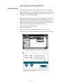
1
Thermo Scientific ULT-80 & ULT-95 Low Temperature Bath Circulators Thermo Scientific Manual P/N U00487 Rev. 07/08/2015 Installation Operation Visit our Web site at: http://www.thermoscientific.com/tc Product Service Information, Applications Notes, MSDS Forms, e-mail. Voice Info: (800) 258-0830 Thermo Scientific ULT-80 & ULT-95 Low Temperature Bath Circulators Thermo Scientific Manual P/N U00487 Rev. 07/08/2015 Installation Operation Visit our Web site at: http://www.thermoscientific.com/tc Product Service Information, Applications Notes, MSDS Forms, e-mail. Voice Info: (800) 258-0830 Thermo Fisher Scientific Sales, Service, and Customer Support 25 Nimble Hill Road Newington, NH 03801 Tel : (800) 258-0830 or (603) 436-9444 Fax : (603) 436-8411 www.thermoscientific.com/tc 25 Nimble Hill Road Newington, NH 03801 Tel: (800) 258-0830 Sales: 8:00 am to 5:00 pm Service and Support: 8:00 am to 6:00 pm Monday through Friday (Eastern Time) Fax: (603) 436-8411 [email protected] Dieselstrasse 4 D-76227 Karlsruhe, Germany Tel : +49 (0) 721 4094 444 Fax : +49 (0) 721 4094 300 [email protected] Building 6, No. 27 Xin Jinqiao Rd., Shanghai 201206 Tel : +86(21) 68654588 Fax : +86(21) 64457830 [email protected] Statement of Copyright Copyright © 2015 Thermo Fisher Scientific. All rights reserved. This manual is copyrighted by Thermo Fisher Scientific. Users are forbidden to reproduce, republish, redistribute, or resell any materials from this manual in either machine-readable form or any other form. ULT 80 and ULT 95 Table of Contents Preface Compliance ............................................................................................... 3 WEEE/RoHS ............................................................................................ 3 After-sale Support .................................................................................... 3 Unpacking ................................................................................................. 3 Out of Box Failure ..................................................................................... 3 Warranty ................................................................................................... 3 Section I Safety Warnings ................................................................................................... 4 Section II General Information Description ................................................................................................ 5 Specifications ............................................................................................ 5 Section III Installation Site ........................................................................................................... 7 Electrical Requirements ............................................................................ 7 Plumbing Requirements ............................................................................ 8 Fluids ........................................................................................................ 8 Filling Requirements .................................................................................. 8 Flow Control ............................................................................................. 9 Nitrogen Purge .......................................................................................... 9 Drain ......................................................................................................... 9 Section IV Operation Start Up .................................................................................................. 10 Controller Keypad & Display ................................................................... 10 Changing a Value .................................................................................... 11 Controller Displays .................................................................................. 11 Operator's Loop ..................................................................................... 12 Setup Loop ............................................................................................. 12 Error Messages ...................................................................................... 15 High Temp/Low Liquid Level Safety ........................................................ 15 9-Pin Accessory Connector ..................................................................... 16 Analog Interface ..................................................................................... 17 Section V Maintenance & Troubleshooting Service Contracts ................................................................................... 18 Cleaning .................................................................................................. 18 Rust ........................................................................................................ 18 Checklist ................................................................................................. 18 Service Assistance .................................................................................. 20 Technical Support ................................................................................... 20 ULT 95 Rear View .................................................................................. 21 ULT 95 Left Side View ............................................................................ 21 ULT 80 Right Side View .......................................................................... 22 ULT 80 Left SideView ............................................................................. 22 Additional Loops .................................................................................... 23 Calibration Loop ..................................................................................... 24 Calibration Procedure ............................................................................. 24 -1- Appendix A Serial Communications Protocol Appendix B Programming Software Declaration of Conformity WARRANTY -2- Preface Compliance WEEE/RoHS After-sale Support Refer to the Declaration of Conformity in the back of this manual. Thermo Fisher Scientific has contracted with one or more recycling/disposal companies in each EU Member State, and this product should be disposed of or recycled through them. Further information on Thermo Fisher Scientific’s compliance with these Directives, the recyclers in your country, and information on Thermo Scientific products which may assist the detection of substances subject to the RoHS Directive are available at: www.thermofisher.com/WEEERoHS Thermo Fisher Scientific is committed to customer service both during and after the sale. If you have questions concerning the operation of your circulator or the information in this manual, contact our Sales Department. If your circulator fails to operate properly or if you have questions concerning spare parts or Service Contracts, contact our Service Department. Before calling, please refer to the serial number label to obtain the following: - BOM number _________________________ - Serial number _________________________ - Software version (see page 23) ___________ Unpacking Retain all cartons and packing material until the circulator is operated and found to be in good condition. If the circulator shows external or internal damage, or does not operate properly, contact the transportation company and file a damage claim. Under ICC regulations, this is your responsibility. Out of Box Failure An Out of Box Failure is defined as any product that fails to operate in conformance with sellers published specifications at initial power up. The circulator must be installed in accordance with manufacturer's recommended operating conditions within 30 days of shipment from the seller. Any Thermo Fisher Scientific product meeting the definition of an Out of Box Failure must be packed and shipped back in the original packaging to Thermo Fisher Scientific for replacement with a new circulator; Seller to pay the cost of shipping. Customer must receive a Return Material Authorization (RMA) from Thermo Fisher prior to shipping the circulator. Warranty Circulators have a warranty against defective parts and workmanship for one full year from date of shipment. See back page for more details. -3- Section I Safety Warnings Make sure you read and understand all instructions and safety precautions listed in this manual before installing or operating your circulator. If you have any questions concerning the operation of your circulator or the information in this manual, contact our Sales Department (see After-sale Support). Performance of installation, operation, or maintenance procedures other than those described in this manual may result in a hazardous situation and may void the manufacturer's warranty. Transport the circulator with care. Sudden jolts or drops can damage the refrigeration lines. Observe all warning labels. Never remove warning labels. Never operate damaged or leaking equipment. Never operate the circulator without cooling fluid in the bath. Always turn off the circulator and disconnect the line cord from the power source before performing any service or maintenance procedures, or before moving the circulator. Always empty the bath before moving the circulator. Never operate equipment with damaged line cords. Refer service and repairs to a qualified technician. For proper travel, the compressors' support springs are tightened prior to shipping. The springs (four per compressor) must be loosened before operating the circulator. Remove the rear and side panels for easy access to the compressors and springs. or In addition to the safety warnings listed above, warnings are posted throughout the manual. These warnings are designated by an exclamation mark inside an equilateral triangle with text highlighted in bold print. Read and follow these important instructions. Failure to observe these instructions can result in permanent damage to the circulator, significant property damage, personal injury or death. -4- Section II General Information Description The Thermo Scientific ULT 80 and ULT 95 are self-contained refrigerated bath/circulators. The circulators consist of a circulating pump; heater; stainless steel reservoir; microprocessor temperature controller; and a cascade configuration, air-cooled refrigeration system. The refrigeration control is independent of the main power switch so that the compressor may be turned off to allow fast warm-up. The automatic load reset feature compensates the proportioning for changes in the bath load, thereby eliminating shifts in setpoint accuracy. Specifications ULT 80 ULT 95 Temperature Range1 -80°C to +10°C -90°C to -30°C Temperature Stability ± 0.03°C ± 0.2°C Cooling Capacity2,3 250 watts at -70°C 340 watts at -80°C Work Area Dimensions4 (L x W x D) Inches Centimeters 53/8 x 7 x 9½ 13.7 x 17.8 x 24.1 2" DIA Fill Hole 5.1 cm Fill Hole 2 x 1 H.P. 2 x 1.5 H.P. 1200 watts 1650 watts Compressor Heater Working Volume Gallons Liters Circulator Dimensions (H x W x D) Inches Centimeters 4.0 15.1 47½ x 273/8 x 17¾ 120.7 x 69.5 x 45.1 48 x 321/8 x 21½ 121.9 x 81.6 x 54.6 336 152.4 370 168.0 Pump “Z” Pump (Force/Suction) "H" Pump (Force only) Pump Head5 60 Hz 50 Hz Max. Head 12' (3.7M) Max. Head 10' 10" (3.3M) Weight Pounds Kilograms Flow5 60 Hz 50 Hz 0-10 liters/minute at 0' Head 0-10 liters/minute at 0' Head Max. Head 31' (9.4M) Max. Head 21' (6.4M) 0-16.0 liters/minute at 0' Head 0-12.4 liters/minute at 0' Head 1. 50 Hz ULT 95 circulators -85°C to -30°C. ULT 80 +80°C temperature range circulators are available, these circulators have 2400 watt heaters (BOMs 180104201601 and 180106201601). 2. 200 watts for ULT 80, 50 Hz operation. 280 Watts for ULT 95, 50 Hz operation. 3. Cooling capacity is affected by ambient temperature - cooling capacity will decrease at the rate of 1% per °F above 75°F. 4. Usable depth for ULT-80 is 8 inches. 5. Using fluid with specific gravity of 1.0. -5- 900 Cooling Capacity 800 A Herat Load (Watts) 700 B 600 C 500 400 D 300 200 100 -80 -60 Pumping Capacity -40 -20 0 Temperature (°C) 20 40 Meters Feet 9.8 32 A=ULT-95, 60HZ B=ULT-95, 50HZ C=ULT-80, 60HZ D=ULT-80, 50HZ Pressure A 7.3 24 4.9 16 2.4 8 B C D 4 1 8 2.2 Flow 12 3.1 16 Lpm 4.2 Gpm 40 Time to Temperature A=ULT-80, 60HZ B=ULT-95, 60HZ Temperature 20 0 -20 A -40 -60 -80 B 30 -6- 60 90 Time (Minutes) 120 Section III Installation Site The refrigeration system requires that the circulator must be located on a level surface. Never place the circulator in a location where excessive heat, moisture, or corrosive materials are present. Locate the circulator in a laboratory or clean industrial environment. Ambient Temperature Range 10°C to 35°C (50°F to 95°F) Overvoltage Category II Pollution Degree 2 Circulators have an air-cooled refrigeration system. Air is drawn through the front and discharged through side and rear panels. Position the circulator so the intake and discharge are not impeded. A minimum clearance of 3 feet (1 meter) on all four sides is necessary for adequate ventilation. Inadequate ventilation will reduce cooling capacity and, in extreme cases, can cause compressor failure. Excessively dusty areas should be avoided and a periodic cleaning schedule should be instituted (see Section V, Cleaning). The circulator will retain its full rated capacity in ambient temperatures up to approximately +75°F (+24°C). Reduce the cooling capacity 1% for every 1°F above +75°F, up to a maximum ambient temperature of +95°F. In terms of °C, reduce the cooling capacity 1% for every 0.5°C above +24°C, up to a maximum ambient temperature of +35°C. Electrical Requirements The circulator construction provides protection against the risk of electrical shock by grounding appropriate metal parts. The protection will not function unless the power cord is connected to a properly grounded outlet. It is the user's responsibility to assure a proper ground connection is provided. Refer to the serial number label on the rear of the circulator to identify the specific electrical requirements. Make sure the voltage of the power source meets the specified voltage, ±10%. -7- Plumbing Requirements Before installing the circulator to an instrument that previously used tap water as a cooling fluid, flush the instrument several times to remove any rust or scale that has built up. The manufacturer of the instrument should be able to recommend a cleaning fluid for their equipment. The inlet/outlet connections are located on the right side of the control box. These connections are 3/8" O.D. stainless steel serrated pipes, which will accept 3/8" or 5/16" I.D. tubing. Connect the pump inlet to the outlet of the external system. Connect the outlet to the inlet of the internal system. Ensure plugs are installed on the inlet/outlet if you are not circulating to an external system. Flexible tubing, if used, should be of heavy wall or reinforced construction. Make sure all tubing connections are securely clamped. Avoid running tubing near radiators, hot water pipes, etc. If substantial lengths of tubing are necessary, insulation may be required to prevent loss of cooling capacity. It is important to keep the distance between the circulator and your application as short as possible, and to use the largest diameter tubing practical. Tubing should be straight and without bends. If reductions must be made, make them at the inlet and outlet of your application, not at the circulator. If substantial lengths of cooling lines are required, pre-filled the lines with cooling fluid before connecting them to the circulator. Fluids Do not use flammable or corrosive fluids with this circulator. The selected cooling fluid should have a viscosity of 50 centistokes or less at the lowest operating temperature. When operating below +8°C, use a nonfreezing fluid. Filling Requirements Never run the circulator when the bath is dry. Fill the bath to within ¾ inch of the top plate. Low fluid level in the bath can cause serious damage to the pump and the reservoir heater. Always maintain the level to within ¾ inch of the top plate. When pumping to an external system, be sure to have additional bath fluid on hand to compensate for the loss of volume to that system. -8- Flow Control ULT 80s are equipped with a flow adjustment control knob. The knob is located directly in front of the control panel on the right side. When shipped, the flow is completely off. (Check that flow is off before starting.) To start flow, turn the knob in a counterclockwise direction until desired flow is obtained. Full flow is obtained by turning the knob approximately 3½ rotations. To avoid damage, do not overtighten the adjustment knob in either the open or closed position. Nitrogen Purge NOTE: This is a standard feature on ULT 95s, an optional feature for ULT 80s. The nitrogen purge valve is designed to accept a constant flow of dry nitrogen into the reservoir. The nitrogen blankets the cooling fluid, preventing air oxidation and water absorption. Remove the reservoir cover by removing the screws. Fill the reservoir with cooling fluid following the procedure listed above. Replace the cover and screws. Connect the nitrogen line to the valve on the reservoir cover. Use a pressure regulator, set to 0.5 psig (0.035 kg/cm2) or lower, to prevent fluid overflow. Drain A reservoir drain is located on the rear of the circulator. The drain is a Parker 6PNBZ plug. -9- Section IV Operation Start Up Before starting, check all electrical, plumbing, and inlet/outlet connections; and make sure the work area has been properly filled with bath fluid. To start the bath, place the MAIN ON/OFF switch to the ON position. The pump will start and the controller will display the temperature of the fluid in the reservoir. (The controller may display Er21 until the reservoir fluid temperature drops within 5°C of the circulator's high-end temperature range, see page 15.) To start the refrigeration system place the REFRIGERATION ON/OFF switch to the ON position. NOTE: For high-temperature circulators the refrigeration automatically shuts down above 35°C. The light in the REFRIGERATION ON/OFF switch will also extinguish. If rapid cool down is needed above 35°C immerse a tap water cooling coil into the reservoir. Either of these methods can also be used to increase stability. Once the cooling system has been turned off, it should remain off for approximately 10 minutes before attempting to restart. Failure to allow this time for pressure equalization within the refrigeration system could cause the compressors to cycle on their overloads. Controller Keypad & Display The microprocessor controller maintains temperature using a ProportionalIntegral-Derivative (PID) algorithm. It is designed with self-diagnostic features and easy to use operator interface. The controller's HEAT indicator shows the status of the heater. The HEAT indicator is lit when the heater is on. The HEAT indicator flashes when the heater is pulsating. - 10 - The REMOTE indicator illuminates whenever the circulator is configured to accept a remote setpoint. The controller's SENSOR indicator illuminates whenever the external sensor is selected. See Controller Displays on the next page. NEXT ENTER Use this key to scroll forward through the menus and also to accept and save changes. YES, This dual purpose key is used to answer yes to YES/NO questions or to increment numerical values upward for setting numeric values. NO, This dual purpose key is used to answer no to YES/NO questions or to decrement numerical values downward for setting numeric values. Changing a Value The YES key increments the value. The NO key decrements the value. The display will flash as soon as either key is depressed, and will continue to flash until the NEXT ENTER key is pressed twice to accept the new value. The new value will not be used by the controller until the NEXT ENTER key is depressed twice and the display stops flashing. NOTE: If the ENTER key is not depressed twice within 10 seconds, the controller will time out and the new value will not be accepted. The controller will revert to the previous setpoint value. Controller Displays An alphanumeric display presents numeric readings of various operating conditions within the bath. Display function is selected by pressing the appropriate keys to move through a menu of available information. When the controller is first powered up it performs a quick self-test then enters the Operator's Loop. The Operator's Loop displays the bath temperature and is used to change the setpoint, see Figure 1 on next page. The Setup Loop can be accessed from the Operator's Loop by pressing and holding the key combinations shown on Figure 1. The Setup Loop is used to adjust the controller's PID parameters, select the internal or external sensor, select a remote setpoint source, and set the high/low temperature limits. It is also used to select and configure RS-232 operation. See Figure 2 on pages 13-14. - 11 - Operator's Loop When the controller is first powered up it enters the Operator's Loop, displaying reservoir fluid temperature. Press the NEXT ENTER key to view the setpoint. SP displays the controller setpoint. The display will flash between SP and the actual setpoint number. Use the YES/NO keys to change the setpoint value. Once the desired setpoint is displayed, press the NEXT ENTER key twice. NOTE: If the bath is controlled via RS-232 communications, the setpoint can not be changed from the keypad. HOLD XXX.X NO NEXT ENTER NEXT ENTER NEXT ENTER GO TO SETUP LOOP XXX.X = Reservoir Fluid Temperature SP = Setpoint SP NEXT ENTER Figure 1 Operator's Loop Setup Loop The Setup Loop is used to adjust the controller's PID parameters; select the internal (1) or external (2) sensor; select a remote setpoint source; set the high/low temperature limits; and select and configure RS-232 operation. Enter the Setup Loop from the Operator's Loop by pressing and holding the NO key, then press the NEXT ENTER key. Use the YES/NO keys to adjust the values. Press the NEXT ENTER key twice to accept the new value. While in the Setup Loop, if any key is not pressed during a one-minute time span, the controller will automatically return to the Operator's Loop temperature display. NOTE: If the circulator exceeds either temperature limit, the appropriate error message will flash, see page 15. The circulator will not shut down (unless the temperature exceeds the high temperature safety setting, see page 15). You will also receive an error code if the optional external sensor is selected but it is not installed. - 12 - tUnE = Tune HEAt = Heat PID Parameters Pro = Proportional Band (factory value 1.5%) Int = Integral (factory value 0.75 repeats per minute) dEr = Derivative (factory value 0.05 minutes) rtd = Sensor 1 = Internal 2 = External SP = Remote setpoint source, see page 17 Hit = High Temperature Limit Figure 2 Setup Loop (1 of 2) - 13 - Hit = High Temperature Limit Lot = Low Temperature Limit r232 = RS232 Protocol bAUd = BAUD rate (default 9600) dAtA = Data bits (default 8) StoP = Stop bit (default 1) PAR = Parity (default none) Stor = Store Figure 2 Setup Loop (2 of 2) NOTE: Should you desire to return to the temperature display and abort all changes, keep pressing the NEXT ENTER until the display reads Stor, then press NO. - 14 - Error Messages Error Action Er00: Er01: Er02: Er04 - Er13: Er14: Er15: Er16: Er19: Er21: Er23: Er24: Er25: Er26: HTC: Er52: ROM Checksum RAM Test Failed Keypad Test Failed Interrupt Error Synchronous Error Asychronous Error Bad Calibration Low Temp Limit High Temp Limit RTD2 Shorted RTD2 Open/Not Installed RTD1 Shorted RTD1 Open High Temperature Cutout System Error NOTE: On start up Er21 is active until the reservoir fluid temperature drops within 5°C of the circulator's high-end temperature range. Errors 00 through 15 will lockup the controller keypad. Errors 00 through 03 may be cleared by depressing the NEXT ENTER key. High Temp/ Low Level Cutout To protect your application, the adjustable High Temperature/Low Liquid Level Safety (HIGH TEMP/LOW LEVEL) ensures the heater will not exceed temperatures that can cause serious damage to your circulator. A single temperature sensor, located on the heater coils in the bath, monitors both conditions. A High Temperature/Low Liquid Level fault occurs when the temperature of the sensor exceeds the set temperature limit. In the event of a fault, the circulator will shut down. The cause of the fault must be identified and corrected before the circulator can be restarted. The safety is not preset and must be adjusted during initial installation. To set the safety, locate the HIGH TEMP/LOW LEVEL SAFETY adjustment dial on the rear of the pump box. Turn the dial fully clockwise and turn the Power switch OFF then back ON. Start the circulator. Adjust the setpoint for a few degrees higher than the highest desired fluid temperature and allow the bath to stabilize at the temperature setpoint. Turn the HIGH TEMP/LOW LEVEL SAFETY dial counterclockwise until you hear a click and the circulator shuts down. The FAULT LED will light to indicate a fault has occurred. Cool the bath and then, without moving the adjustment dial, turn the Power switch OFF then back ON. NOTE: The safety switch has a temperature range of 7°C to 180°C. - 15 - 9-Pin Accessory Connector The circulator is equipped with two 9-pin D-connectors located on the rear of the control box. The female COMM is used for RS232 communication (see Appendix); the male is used with an optional external sensor. RS232 Pin Connections Pin # 1 2 3 4 5 6 7 8 9 Hardware Function No connection. TX = Transmitted data from controller RX = Received data to controller No connection GND = Signal ground No connection. CTS = Clear to send RTS = Request to send No connection Internal Connector AMP Part# 745491-2 Mating Connector AMP Part# 745492-2 Remote Sensor Connections Function 3-wire RTD connection A 2 3 4 5 6 7 8 9 No connection No connection 3-wire RTD connection A No connection No connection. 3-wire RTD connection B No connection No connection Hardware Internal Connector AMP Part# 745492-2 - 16 - Example RTD Pin # 1 Mating Connector AMP Part# 745491-2 Analog Interface An 15-pin D subminiature female receptacle for analog interface is located on the rear of the control/pump box. ACCESSORY Pin # Function 1 Chassis ground. 2 No connection. 3-5 No connection. 6 Analog Ground. The analog ground is physically separated from the power ground throughout the circulator. To prevent offsets that result from ground currents, the analog and power grounds are only connected at the circulator's power supply. Analog ground should only be used as a reference pin . 7 Temperature Out. The fluid temperature, as measured by the controller’s sensor located in the reservoir, can be read at this pin. The temperature scale is 10mV/°C, referenced to analog ground, pin 6 (example: +150mV = +15.0°C). 8 No connection. 9 Power Ground (5V RTN). 8 7 15 6 14 5 13 4 12 3 11 2 10 1 9 15 pin D-subminiature female receptacle 10 - 13 No connection. 14 +5V. Power supply of +5VDC (15mA maximum). 15 Setpoint In. The temperature setpoint can be controlled by applying a known voltage to this pin. The temperature scale is 10mV/°C, referenced to analog ground, pin 6 (example: +230mV = +23.0°C). Note: The setpoint is updated only when the voltage represents a temperature within the setpoint limits. The analog setpoint signal (Setpoint In) is enabled using the circulator's software. Using the Setup Loop discussed on pages 12 - 14, keep depressing the NEXT ENTER key until SP is displayed. Use the YES or NO key to display the desired mode, AnA for analog or LoC for local, then press NEXT ENTER twice to continue with the loop. NOTE: The last value entered is maintained when SP is changed from AnA to LOC or LOC to AnA. Store the changes. - 17 - Section V Maintenance & Troubleshooting Service Contracts Service Contracts are designed to provide extended life and minimal downtime for your circulator. For more information, contact our Service Department. Cleaning Periodically inspect the reservoir. If cleaning is necessary, flush the reservoir with a cleaning fluid compatible with both the circulating system (if applicable) and the cooling fluid. Do not use steel wool; its too abrasive and will lead to rusting. Dry the bath using a soft cloth. Also, cooling fluid should be replaced periodically when operating at low temperatures. Moisture concentration in cooling fluid will increase with time leading to a build up of ice on the cooling coil. Raise the temperature of the bath to deice the cooling coil. Shut the circulator off, and replace the cooling fluid. Periodic vacuuming of the condenser fins is necessary. The frequency of cleaning depends on the operating environment. We recommend a monthly visual inspection of the condenser after initial installation. After several months, the frequency of cleaning will be established. Rust Stainless steel will rust if not properly used and maintained. Any damage, such as scratching or pitting, can cause rusting. The stainless steel parts exposed to bath fluids should be thoroughly cleaned periodically. Checklist Circulator Will Not Start Check High Temperature/Low Level cutout (see Section IV, High Temp/Low Level Cutout). Check all circuit breakers. Check power source for correct voltage output. Check line cord wiring (see Section III, Electrical Requirements). - 18 - Loss of Cooling Capacity Check cooling capacity specifications (see Section II, Specifications). Check temperature setpoint. Check to ensure that external heat load has not overcome the cooling capacity at the desired working temperature. If the circulator starts and no cooling occurs, listen for a clicking sound from the inside of the circulator. The clicking is an indication of compressor shortcycling. Check the following for causes of compressor short-cycling: If the circulator is shut off for any reason, allow it to remain off for approximately ten minutes before attempting to restart. The refrigeration compressor will short-cycle if time is not allotted for the equalization of refrigerant pressures. Standard circulators are not designed for high temperature applications. If the cooling coils are subjected to temperatures above the maximum high temperature for the circulator, compressor short-cycling will occur. For high-temperature circulators the refrigeration automatically shuts down above 35°C. The light in the switch will also extinguish. If the power source is 10% below the circulator’s voltage requirements, the compressor will short-cycle. Check power source for correct voltage output. When operating below 8°C, a non-freezing solution must be added to the bath fluid. At low temperature, a higher concentration of the non-freezing solution is required to prevent ice build up on the circulator’s cooling coil. This ice build up will act as insulation and reduce the cooling capacity. Raise the temperature of the bath to deice the cooling coil and increase the concentration of the non-freezing solution. Also, replace the bath fluid periodically when operating at low temperatures. Moisture concentration in the bath fluid will increase with time leading to ice buildup. Circulator Will Not Heat Check the temperature setpoint to be certain that it is at your desired temperature (see Section IV, Operator's Loop). Check the circulator configuration in the controller's Setup Loop. - 19 - No Temperature Control If recirculating to an external system, do not exceed the cooling capacity of the circulator. Exceeding the circulator's cooling capacity results in a loss of temperature control. No External Circulation On ULT 80s, make certain adjustable Flow Control is open (turn counterclockwise). Check for plug in external system line. Recirculation will cease when pump head pressure is exceeded. Review pump specifications (see Section II, Specifications). No serial communications All circulators are tested for serial communications before they leave the factory. Ensure the REMOTE indicator on the controller is illuminated. Check all communications commands, they must be exact. See Appendix A. Check communications settings. The protocol uses an RS-232 serial interface with the parameters: 9600 baud, 8 data bits, 1 stop bit and no parity. Check all wiring for proper connections or possible shorts. Software to verify serial communication is available from Thermo Fisher. Service Assistance If, after following these troubleshooting steps, your circulator fails to operate properly, contact our Service Department for assistance (see Preface, Aftersale Support). Before calling please obtain the following information: Part number Serial number Voltage of power source Software version, see page 23 Technical Support Our Service Department can provide you with a complete list of spare parts for your circulator (see Preface, After-sale Support). Before calling, please obtain the following information: Part number Serial number - 20 - ULT-95 Rear View ULT-95 Left Side View - 21 - ULT-80 Left SideView L = Low stage H = High stage ULT-80 Right Side View - 22 - - 23 - Calibration Loop The Calibration Loop is used to calibrate the RTD high and low temperature. The controller's internal temperature sensor is factory calibrated. We recommend calibrating any external sensor. Enter the Calibration Loop from the Operator's Loop by pressing and holding the NO key while pressing the YES key three times. Calibration Procedure Install a calibrated reference thermometer in the bath. (For external mode, also install the sensor in the bath.) Place the cover on the circulator. The procedure uses the Operator's, Setup and Calibration Loops. In the Setup Loop place the circulator in either the internal or remote RTD mode of operation (RTD1 = Internal , RTD2 = External). Return to the Operator's Loop and adjust the setpoint to an appropriate high-end temperature. NOTE: When calibrating the external sensor ensure the controller's SENSOR indicator is illuminated. Once the bath reaches the setpoint and stabilizes, go to the Calibration Loop and, as illustrated on the next page, enter the actual reference thermometer reading at either the r1H or r2H prompt. Store the change and return to the Operator's Loop. Adjust the setpoint to an appropriate low-end temperature. Once the bath reaches the setpoint and stabilizes, return to the Calibration Loop and enter the reference thermometer reading at either the r1L or r2L prompt. Store the change. Do not pick points that are outside the safe operating limits of the circulator and the fluid in your application. Analog In calibration is done by applying a 10.000Vdc signal for AiH, and a 0.000Vdc signal for AiL. Reference the appropriate pins on the ACCESSORY connector. Analog Out calibration is done by measuring the appropriate pins on the ACCESSORY connector. Adjust the AoH to 1.000Vdc using the YES and NO keys then press ENTER twice. Adjust the AoL to 0.000Vdc using the YES and NO keys then press ENTER twice. - 24 - rtdn n= 1 = Internal sensor, n = 2 = external sensor rnH = High temperature rnL = Low temperature Ain = Analog in Aout = Analog out Stor = Store Figure 4 Calibration Loop NOTE: To stor all changes, when the display reads Stor press YES. Should you desire to return to the temperature display and abort all changes, when the display reads Stor press NO. - 25 - Appendix A Serial Communications Protocol NOTE: This appendix assumes you have a basic understanding of communications protocols. All data is sent and received in binary form, do not use ASCII. In the following pages the binary data is represented in hexadecimal (hex) format. The NC Serial Communications Protocol is based on a master-slave model. The master is a host computer, while the slave is the bath's controller. Only the master can initiate a communications transaction (half-duplex). The slave ends the transaction by responding to the master’s query. The protocol uses an RS-232 serial interface with the default parameters: 9600 baud, 1 start bit, 8 data bits, 1 stop bit and no parity. NOTE: Before the circulator will communicate, RS-232 must be turned on in the controller's Setup Loop. The circulator can be controlled through your computer’s serial port by using a standard 9-pin RS-232 connection on the rear of the temperature controller. Data transmit of the computer's serial port connects to data read (pin 3) of the bath. Data read of the computer's serial port connects to the data transmit (pin 2) of the bath. Communication cables are available. Contact our sales department for additional information. All commands must be entered in the exact format shown in the tables on the following pages. Table 1 shows all commands available, their format and responses. Controller responses are either the requested data or an error message. The controller response must be received before sending the next command. The host sends a command embedded in a single communications packet, then waits for the controller’s response. If the command is not understood or the checksums do not agree, the controller responds with an error command. Otherwise, the controller responds with the requested data. If the controller fails to respond within 1 second, the host should re-send the command. - 26 - NC Serial Communications Protocol NOTE: All byte values are shown in hex, hex represents the binary values that must be sent to the bath. Do not use ASCII. The framing of the communications packet in both directions is: Checksum region Lead char CA Addr-MSB 00 Addr-LSB Command 01 n d-bytes d-byte 1 ... d-byte n Checksum Lead char CA (hex). Addr-msb Addr-lsb Device address is 1 Most significant byte of device address is 00 hex. Least significant byte of device address is 01 hex. Command Command byte (see Table 1). n d-bytes d-byte 1 ... d-byte n Checksum Number of data bytes to follow (00 to 03 hex). 1st data byte (the qualifier byte is considered a data byte). ... nth data byte. Bitwise inversion of the 1 byte sum of bytes beginning with the most significant address byte and ending with the byte preceding the checksum. (To perform a bitwise inversion, "exclusive OR" the one byte sum with FF hex.) The master requests information by sending one of the Read Functions as shown in Table 1. Since no data is sent to the bath during a read request, the master uses 00 for the number of data bytes following the command byte. The bath will respond to a Read Function by echoing the lead character, address, and command byte, followed by the requested data and checksum. When the bath sends data, a qualifier byte is sent first, followed by a two byte signed integer (16 bit, MSB sent first). The qualifier byte indicates the precision and units of measure for the requested data as detailed in Table 2. As an example, the master requests to read internal temperature by sending: The checksum is the bitwise inversion of 21 (00+01+20+00) command byte CA 00 01 20 00 DE byte values are in hex 0 bytes of data If the temperature is -10.5°C, the bath would reply: The qualifier byte of 11 indicates a precision of 1 decimal point and units of °C. The temperature of -10.5°C is -105 decimal = FF97 hex. command byte CA 00 01 20 03 11 FF 97 34 The checksum is the bitwise inversion of CB (00+01+20+03+11+FF+97) 3 bytes to follow - 27 - The master sets parameters in the bath by sending one of the Set Functions as shown in Table 1. The master does not send a qualifier byte in the data field. The master should be preprogrammed to send the correct precision and units (it could also read the parameter of interest first to decode the correct precision and units needed). For example, if the master wants to set the setpoint to 30°C, it would send : The checksum is the bitwise inversion of 20 (00+01+F0+02+01+2C) command byte CA 00 01 F0 02 01 2C DF 2 bytes to follow The temperature of 30.0°C is 300 decimal = 012C hex. The bath responds: The qualifier byte of 11 indicates a precision of 1 decimal point and units of °C. The temperature of 30.0°C is 300 decimal = 012C hex. command byte CA 00 01 F0 03 11 01 2C CD The checksum is the bitwise inversion of 32(00+01+F0+03+11+01+2C) 3 bytes to follow - 28 - Table 1 (All bytes are in hex) FUNCTION MASTER SENDS BATH RESPONDS READ Read Internal Temperature Read External Sensor Read Setpoint (control point) Read Low Temperature Limit Read High Temperature Limit Read Proportional Band (P) Read Integral (I) Read Derivative (D) CA 00 01 20 00 DE CA 00 01 21 00 DD CA 00 01 70 00 8E CA 00 01 40 00 BE CA 00 01 60 00 9E CA 00 01 71 00 8D CA 00 01 72 00 8C CA 00 01 73 00 8B CA 00 01 20 03 qb d1 d2 cs CA 00 01 21 03 qb d1 d2 cs CA 00 01 70 03 qb d1 d2 cs CA 00 01 40 03 qb d1 d2 cs CA 00 01 60 03 qb d1 d2 cs CA 00 01 71 03 qb d1 d2 cs CA 00 01 72 03 qb d1 d2 cs CA 00 01 73 03 qb d1 d2 cs SET Set Setpoint (control point)* Set Low Temperature Limit* Set High Temperature Limit* Set Proportional Band (P=1-99.9) Set Integral (I = 0-9.99) Set Derivative (D= 0-5.0) CA 00 01 F0 02 d1 d2 cs CA 00 01 C0 02 d1 d2 cs CA 00 01 E0 02 d1 d2 cs CA 00 01 F1 02 d1 d2 cs CA 00 01 F0 03 qb d1 d2 cs CA 00 01 C0 03 qb d1 d2 cs CA 00 01 E0 03 qb d1 d2 cs CA 00 01 F1 03 qb d1 d2 cs CA 00 01 F2 02 d1 d2 cs CA 00 01 F3 02 d1 d2 cs CA 00 01 F2 03 qb d1 d2 cs CA 00 01 F3 03 qb d1 d2 cs BATH ERROR RESPONSES Bad Command Bad Checksum N/A N/A CA 00 01 0F 02 01 ed cs CA 00 01 0F 02 03 ed cs MISCELLANEOUS Request Acknowledge CA 00 01 00 00 FE CA 00 01 00 02 v1 v2 cs command bytes shown in bold qb = qualifier byte d1,d2 = 16 bit signed integer of the value being sent or received cs = the checksum of the string (see text) ed = echo back of the command byte as received v1,v2 = protocol version * = limited to the range of the bath Table 2 QUALIFIER BYTE 10 hex 20 hex 11 hex 0.1 precision, no units of measure 0.01 precision, no units of measure 0.1 precision, °C units Example: The temperature of 45.6 °C would be represented by the qualifier 11 hex, followed by the 2 bytes 01 C8 hex (456 decimal). - 29 - Appendix B Programming Software NEScom Software The Thermo Fisher Scientific Communications Software is a user friendly software that allows you to automate your temperature control process. The software includes a 3½" disk, comprehensive operator’s manual and a tollfree number to a trained technical staff. NEScom Software allows you to write custom temperature programs for our Digital or Microprocessor based temperature control apparatus. Choose upper or lower temperature limits and monitor system status with an alarm. NEScom can also record your results on a user selectable graph. NesCom must be used with an IBM or 100% compatible computer. Select from easy to use product icons. Create graphs and charts. Easily configure ramping functions which set the setpoint over time. View pop-up alarm windows which display if an alarm condition occurred. Select software functions from the easy to use pulldown menus. View a virtual controller screen which allows remote monitoring and operation of product control panel. - 30 - Laboratory Equipment Div. 25 Nimble Hill Road Newington, NH 03801 DECLARATION OF CONFORMITY Manufacturer: Address: Thermo Fisher Scientific 25 Nimble Hill Road Newington, NH 03801 We declare that the equipment named below has been designed to comply with the relevant sections of the below referenced specifications and is in accordance with the requirements of the indicated directives. Product: Ultra Low Temperature Bath/Circulators for Process Fluids Models: ULT-80, ULT 95 Directives and Standards: 2004/108/EC ± Electromagnetic Compatibility Directive (EMC) EN 61326-1: 2013 Electrical equipment for measurement, control, and laboratory use - EMC requirements. General requirements 2006/95/EC - Low Voltage Directive (LVD): EN 61010-1: 2010 Safety requirements for electrical equipment for measurement, control, and laboratory use -- Part 1: General requirements. EN 61010-2-010: 2003 Safety requirements for electrical equipment for measurement, control, and laboratory use - Part 2-010: Particular requirements for laboratory equipment for the heating of materials 2011/65/EU – Restriction of the use of certain hazardous substances in electrical and electronic equipment EN 50581: 2012 - Technical documentation for the assessment of electrical and electronic products with respect to the restriction of hazardous substances Authorized representative in the EC: Name: Address: Thermo Fisher Scientific Dieselstrasse 4 76227 Karlsruhe Germany On behalf of the manufacturer: Date: 06/26/2015 13 Mark Sinclair R&D Director Laboratory Equipment Division Thermo Fisher Scientific Newington, NH, USA D of C 098256.1 DWG # 098256 Form 094233-P Rev 14 Sept 11 Warranty Thermo Fisher Scientific warrants for 12 months from date of shipment any Thermo Scientific product according to the following terms. Any part of the circulator manufactured or supplied by Thermo Fisher Scientific and found in the reasonable judgment of Thermo Fisher to be defective in material or workmanship will be repaired at an authorized Thermo Fisher Repair Depot without charge for parts or labor. The circulator, including any defective part must be returned to an authorized Thermo Fisher Repair Depot within the warranty period. The expense of returning the circulator to the authorized Thermo Fisher Repair Depot for warranty service will be paid for by the buyer. Our responsibility in respect to warranty claims is limited to performing the required repairs or replacements, and no claim of breach of warranty shall be cause for cancellation or recision of the contract of sales of any circulator. With respect to circulators that qualify for field service repairs, Thermo Fisher Scientific’s responsibility is limited to the component parts necessary for the repair and the labor that is required on site to perform the repair. Any travel labor or mileage charges are the financial responsibility of the buyer. The buyer shall be responsible for any evaluation or warranty service call (including labor charges) if no defects are found with the Thermo Scientific product. This warranty does not cover any circulator that has been subject to misuse, neglect, or accident. This warranty does not apply to any damage to the circulator that is the result of improper installation or maintenance, or to any circulator that has been operated or maintained in any way contrary to the operating or maintenance instructions specified in this Instruction and Operation Manual. This warranty does not cover any circulator that has been altered or modified so as to change its intended use. In addition, this warranty does not extend to repairs made by the use of parts, accessories, or fluids which are either incompatible with the circulator or adversely affect its operation, performance, or durability. Thermo Fisher Scientific reserves the right to change or improve the design of any circulator without assuming any obligation to modify any circulator previously manufactured. THE FOREGOING EXPRESS WARRANTY IS IN LIEU OF ALL OTHER WARRANTIES, EXPRESSED OR IMPLIED, INCLUDING BUT NOT LIMITED TO WARRANTIES OR MERCHANTABILITY AND FITNESS FOR A PARTICULAR PURPOSE. OUR OBLIGATION UNDER THIS WARRANTY IS STRICTLY AND EXCLUSIVELY LIMITED TO THE REPAIR OR REPLACEMENT OF DEFECTIVE COMPONENT PARTS AND Thermo Fisher Scientific DOES NOT ASSUME OR AUTHORIZE ANYONE TO ASSUME FOR IT ANY OTHER OBLIGATION. Thermo Fisher Scientific ASSUMES NO RESPONSIBILITY FOR INCIDENTAL, CONSEQUENTIAL, OR OTHER DAMAGES INCLUDING, BUT NOT LIMITED TO LOSS OR DAMAGE TO PROPERTY, LOSS OF PROFITS OR REVENUE, LOSS OF THE CIRCULATOR, LOSS OF TIME, OR INCONVENIENCE. This warranty applies to chillers sold by Thermo Fisher Scientific. (Refer to the warranty for baths sold by the affiliated marketing company of Thermo Fisher Scientific for any additional terms.) This warranty and all matters arising pursuant to it shall be governed by the law of the State of New Hampshire, United States. All legal actions brought in relation hereto shall be filed in the appropriate state or federal courts in New Hampshire, unless waived by Thermo Fisher Scientific. Thermo Fisher Scientific 81 Wyman Street P.O. Box 9046 Waltham, Massachusetts 02454-9046 United States www.thermofisher.com