1
Rev 1.0
n
Introduction
n
Front panel facilities and controls
n
Rear Panel Connections
n
SaffireControl LE
n
Recording using a microphone (mono or stereo)
n
Recording line level sources (mono or stereo)
n
Recording a guitar or bass directly
n
Recording a digital (S/PDIF) source
n
Connecting Speakers
n
Managing a recording session with SaffireControl LE
How to set up an input mix on the monitors/headphones
How to set up a playback track mix on the monitors/headphones
Blending between inputs and playback tracks on the monitors/headphones
n
Direct Audio Streaming to the Saffire LE Outputs: Soundcard (S/CARD) mode
n
Direct AC3/DTS streaming to the RCA Output
n
Control and Linking of Output Levels
n
Float and Shrink Modes
n
Setting the Sample Rate and Synchronising to the S/PDIF In
n
Changes to GUI at 88.2/96kHz
n
MIDI
n
Saffire Plug-in Suite
EQ
Compression
Reverb
Amp Sim
n
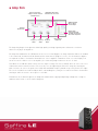
Saffire Signal Flow Diagram
n
Troubleshooting
n
Specifications
n
Warranty
n
Accuracy
n
Copyright
n
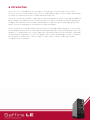
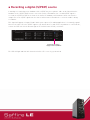
Introduction
Saffire LE is the second addition to the now highly acclaimed range of Firewire audio interfaces from
Focusrite, one of the most prestigious names in the recording industry. With a total of 6 Inputs and 8 Outputs,
the Saffire LE should satisfy all your recording and monitoring needs.
Four of the six inputs are analogue, comprising two expertly designed Focusrite pre-amps and two additional
balanced inputs, switchable between Line and Instrument level signal – just plug in your guitar and play. On
the digital side, unrivalled conversion and 24-bit/96kHz processing ensure professional signal quality, with
S/PDIF connections making up the remaining stereo inputs and outputs.
On the rear panel are 6 analogue Outputs, ideally suited to 5.1 surround mixing or playback, as well as MIDI
I/O and a digital RCA port that can stream digital surround (AC3/DTS) directly from DVD playing software. The
hardware is accompanied by a free software application called SaffireControl LE, which provides a multitiude
of monitoring and setup options, as well as the popular suite of Saffire VST/AU plug-ins for processing in the
mix. Having such comprehensive features readily accessible, Saffire LE makes conducting a modern
recording session easy and fun.
n
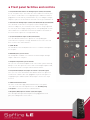
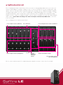
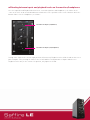
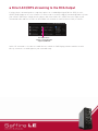
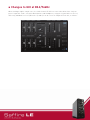
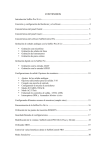
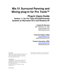
Front panel facilities and controls
1. Line/Instrument Gain Switches for Analogue Inputs 1 (above) and 2 (below)
If a 1/4” Jack (TRS or TS) is connected to either of the LINE IN sockets below, then
these switches can be used to select an appropriate gain calibration. If a Guitar is
plugged in then ensure that the yellow INST LED is lit, or if recording the analogue
output of a synthesizer or mixer for decks then make sure the green LINE LED is lit.
1
2
2. Gain Controls for Analogue Inputs 1 (above) and 2 (below) with O/L (Overload) LEDs
These two knobs can be used to set the gain (level) of the analogue inputs,
whether recording a mic, line or instrument source. Whilst receiving a signal from
the source by the artist singing or playing, rotate the corresponding knob clockwise
until a suitable level is heard. Make sure that the O/L LED does not illuminate as
this means that the signal level is too high and will clip.
3
3. O/L (Overload) LEDs for Inputs 3 (above) and 4 (below)
4
These two LEDs will illuminate if the signal for the corresponding input
5
(connected on the rear panel) is too high. Turn down the level on the connected
device if either of these LEDs illuminates.
6
4. S/PDIF IN LED
This LED indicates that a valid S/PDIF connection is received at the RCA Input on
the rear panel.
5. MONITOR (O/Ps 1/2) Level Control
This knob provides a hardware level control for the Monitor Outputs: Analogue
Outputs 1 and 2 on the rear panel.
8
7
6. Headphones Output with separate Gain Dial
This 1/4” Jack socket allows Headphones to be connected for separate monitoring
during a session. This signal is the same as that sent to Analogue Outputs 3 and 4,
the mix for which can be set using the SaffireControl LE software.
7. Line/Instrument (TRS/TS Jack) Inputs for channels 1 (left) and 2 (right)
These 1/4” Jack sockets allow a balanced or unbalanced Line level signal or an
Instrument like a Guitar or Bass to be plugged directly into the front panel. Set
an appropriate gain calibration (LINE or INST) using the switches at the top of
the fascia.
8. Global Phantom Power Switch
This switch can be used to apply +48V (Phantom Power) to a microphone
connected to either of the XLR inputs below. Check the Recording using
a microphone section for more details on Phantom Power.
9. Microphone (XLR) Inputs for channels 1 (left) and 2 (right)
These two inputs allow up to two microphones to be plugged into the front
panel, for recording mono or stereo sources.
9
n
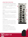
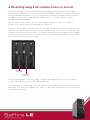
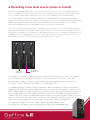
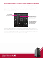
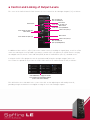
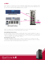
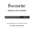
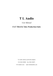
Rear Panel Connections
1. Line/Instrument (TRS/TS Jack) Inputs for channels 3 (below) and 4 (above)
These 1/4” Jack sockets allow a balanced or unbalanced Line level signal or an
Instrument like a Guitar or Bass to be connected. If plugging in an Instrument then
make sure that the High Gain Switch for the corresponding Input is activated within
the SaffireControl LE software. See the SaffireControl LE section for more details.
1
2. External PSU Input
This socket is for powering the Saffire LE using the supplied external power
supply. This is only necessary if Firewire bus powering is not available, for example
if the connected computer only has a 4-pin Firewire port.
2
3. S/PDIF I/O
These RCA connectors are for receiving or transmitting a consumer digital audio
3
(S/PDIF) signal. With the AC3 THRU switch activated in SaffireControl LE, the RCA
Output can be used to directly stream an AC3 or DTS signal from a software DVD
player to a home surround studio setup. See the Direct AC3/DTS streaming to the
RCA Output section for more details.
4. MIDI I/O
These standard MIDI ports allow MIDI data to be received from and transmitted
4
to external equipment, routing through your sequencer using the Saffire LE’s
Firewire interfacing. Alternatively, if the Saffire’s MIDI In is connected to a
controller keyboard’s MIDI Out and the Saffire’s MIDI Out is connected to a sound
module or rack synth’s MIDI In, activating the MIDI Thru switch in the SaffireControl
LE software will enable the MIDI data to pass from the controller keyboard to the
sound module.
5. 2 6-pin Firewire 400 Ports
These ports allow connection to the computer for streaming of data and (if
connected to an identical type of Firewire port, rather than a smaller 4-pin port)
supply of power to the unit. Either port can be used for this purpose, leaving the
additional port free for connecting to other Firewire equipment (e.g. hard drives)
should the Saffire be using up the only available Firewire port on the computer.
The nature of Firewire connectivity means that chaining equipment in this way is
possible and will act as if the equipment is connected directly to the computer
through separate Firewire ports.
6. 6 Balanced Line Outputs: +4dBu, TRS Jack
These sockets are Saffire LE’s Analogue Outputs, labeled accordingly for
5.1 surround: Left, Right, Centre, LeftSurround, RightSurround and
LowFrequencyEffects. If recording, then connect Monitors to Outputs 1 and 2
and Headphones to the front panel socket (Outputs 3/4) and use the software
to create independent mixes for each. If mixing in surround or wanting to stream
multiple channels of audio directly to the hardware outputs from your sequencer,
then connect speakers to the relevant sockets and activate the S/CARD switch in
the SaffireControl LE software.
Saffire LE
USER MANUAL
6
5
n
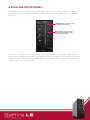
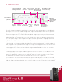
SaffireControl LE
The accompanying software SaffireControl LE is the means of setting up independent latency free mixes for
monitors and headphones, during recording sessions, as well as offering a host of other routing and setting
options. There are two main modes of operation, both with activating switches: TRACK (tracking/recording) is
the default mode and the one to use when recording and creating Input/Playback mixes on Outputs 1-4, and
S/CARD (soundcard) is a preset mode where Saffire LE behaves like a standard 8-out soundcard, routing
Outputs 1-8 in the sequencer straight to Outputs 1-8 of the Saffire LE hardware. To learn more about S/CARD
mode, read the Direct Audio Streaming to the Saffire LE Outputs: Soundcard (S/CARD) mode section later
in the User Guide.
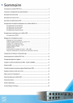
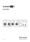
Here is a diagram of the SaffireControl LE GUI:
Levels of Inputs on O/Ps 1/2 (Monitors)
Stereo Link Switch
Levels of Inputs on O/Ps 3/4 (Headphones)
Pan Pot
Levels of Playback Tracks on O/Ps 1/2 (Monitors)
Analogue
Output Level
and Mixing
Controls
Software and Hardware Settings
Levels of Playback Tracks on
O/Ps 3/4 (Headphones)
Each section of SaffireControl LE is explained in greater depth in relevant sections of the User Guide.
n
Recording using a microphone (mono or stereo)
To record a mono source like a vocalist or guitar player, simply plug a microphone into the left (Input 1)
or right (Input 2) hand XLR socket on the front of the Saffire hardware and press the +48V (phantom power)
button if required. Phantom power is only necessary if using a condenser microphone; almost all dynamic
microphones will be unaffected, but ribbon microphones (much less common and more expensive
microphones) may be damaged.
Make sure that nothing is connected to the corresponding Line Input on the front of the Saffire LE
hardware as this will mean that the XLR input below is bypassed.
Now get the artist to play or sing and set the level of the input using the gain adjustment knob on the front
panel. Rotate the dial clockwise to increase the level, making sure that the O/L LED on the hardware never
illuminates as this indicates that the level is exceeding the maximum level of the digital converter (clipping
point). For an even easier indication of level, observe the level of the meter below Input 1 or 2 on the left of
the SaffireControl LE software GUI, as shown:
Level of Input 1
(Recorded level)
Level of Input 2
(Recorded level)
This signal will now appear as Saffire LE Input 1 or Input 2 (depending on which socket the microphone
is connected to) within your sequencer/recording application.
To record using a stereo pair, simply connect microphones to both Inputs 1 and 2 and set the Gain dials for
both Inputs on the front of the hardware to the same level, observing the Input meters in the SaffireControl
LE software, shown above.
n
Recording a line level source (mono or stereo)
All four of the analogue inputs can be used to record a line level source, such as the analogue output of a
mixer or a hardware synth. This means that some decks could be permanently connected to Inputs 3 and 4
on the rear panel, whilst Inputs 1 and 2 where free to use for recording vocal or instrumental parts.
To record using Inputs 1 and/or 2, plug 1/4” TRS (balanced, but TS/unbalanced could be used yielding a
slightly lower level) Jacks into either or both of the LINE IN sockets on the front panel. This will automatically
bypass any microphones that may be connected to the XLR Inputs below. Now make sure that the green
LINE LED is illuminated in the corresponding section(s) at the top of the front panel.
Now send a signal by starting a turntable or playing the synth etc. and set the level of the input(s) using the
gain adjustment knob on the front panel. Rotate the dial clockwise to increase the level, making sure that the
O/L LED on the hardware never illuminates as this indicates that the level is exceeding the maximum level of
the digital converter (clipping point). For an even easier indication of level, observe the level of the meter
below Input 1 or 2 on the left of the SaffireControl LE software GUI, as shown:
Level of Input 1
(Recorded level)
Level of Input 2
(Recorded level)
If recording a stereo signal then make sure that the Gain dials for both Inputs on the front of the hardware
are set to the same level, observing the Input meters in the SaffireControl LE software, shown above.
This signal will now appear as Saffire LE Input 1 and/or Input 2 (depending on which socket(s) the line
level signal is connected to) within your sequencer/recording application.
If recording using Inputs 3 and/or 4, plug 1/4” TRS (balanced, but TS/unbalanced could be used yielding a
slightly lower level) Jacks into either or both of the sockets in the top left of the hardware’s rear panel. Now,
when sending a signal to the Inputs, observe the O/L LEDs for Inputs 3 and 4 on the front of the hardware. If
they are illuminating, check that the High Gain switch/es is/are not activated within the SaffireControl LE
software’s GUI. These switches should only be used if the signal is an Instrument (Guitar or Bass connected
directly) or an extremely low line level source. If the level is too loud and the High Gain switch(es)
is/are not activated, turn down the level of the signal sent to Saffire LE on the sending device.
This signal will now appear as Saffire LE Input 3 and/or Input 4 (depending on which
socket(s) the line level signal is connected to) within your sequencer/recording application.
n
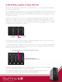
Recording a guitar or bass directly
All four of the analogue inputs can be used to record an Instrument, such as a Guitar or Bass plugged in
directly without using an amp.
To record using Input 1 or 2, plug a 1/4” TS Jack into either of the LINE IN sockets on the front panel, left for
Input 1 and right for Input 2. This will automatically bypass any microphones that may be connected to the
XLR Inputs below. Now make sure that the yellow INST LED is illuminated in the corresponding section at
the top of the front panel.
Now play the Instrument and set the level of the input using the gain adjustment knob on the front panel.
Rotate the dial clockwise to increase the level, making sure that the O/L LED on the hardware never
illuminates as this indicates that the level is exceeding the maximum level of the digital converter (clipping
point). For an even easier indication of level, observe the level of the meter below Input 1 or 2 on the left of
the SaffireControl LE software GUI, as shown:
Level of Input 1
(Recorded level)
Level of Input 2
(Recorded level)
This signal will now appear as Saffire LE Input 1 or Input 2 (depending on which socket the Instrument is
connected to) within your sequencer/recording application.
If recording using Input 3 or 4, plug a 1/4” TS Jack into either of the sockets in the top left of the hardware’s
rear panel, below for Input 3 and above for Input 4. Now, activate the High Gain switch for that Input in the
SaffireControl LE software’s GUI, as follows:
High Gain Switch for Input 3 – engage if an Instrument is connected
High Gain Switch for Input 4 –
engage if an Instrument is connected
Now play the Instrument and observe the O/L LEDs for Inputs 3 and 4 on the front of the hardware.
If they are illuminating, turn down the level on the Instrument.
This signal will now appear as Saffire LE Input 3 or Input 4 (depending on which socket the
Instrument is connected to) within your sequencer/recording application.
n
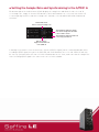
Recording a digital (S/PDIF) source
If wanting to record using some hardware with a S/PDIF Out, then a phono cable can be linked from the
hardware to the S/PDIF (RCA) In on the rear of the Saffire LE hardware. Once a valid S/PDIF signal is
received, the S/PDIF IN LED on the front of the Saffire LE hardware will illuminate. Make sure that the
sample rate of the S/PDIF signal matches that in SaffireControl LE and in the session the audio is being
recorded to.
This signal will appear as Inputs 5 and 6 within your sequencer/recording application. It is normally a good
idea to lock Saffire LE to the S/PDIF signal to synchronize devices and ensure no problems occur. To do this,
activate the EXT switch in the bottom right of the SaffireControl LE GUI, as follows:
External Sync Switch –
engage to lock to S/PDIF In
The LED will light and LOK will show when Saffire LE is correctly synchronized.
n
Connecting Speakers
On the rear panel are balanced (TRS) Jack outputs 1-6 for connecting directly to speakers or an amp
(depending on whether the speakers are powered or not). Outputs 1 and 2 are the Monitors signal so if using
a stereo pair of speakers then connect them to these sockets. Now, the SaffireControl LE software can be
used to create a latency-free mix of inputs and playback tracks using the top rows of faders in the GUI.
The level of the Monitors is controlled by the top dial in the centre of the SaffireControl LE software GUI,
and then by the MONITOR dial on the front of the Saffire LE hardware.
If using a surround setup requiring analogue signals then outputs 1-6 are labeled for 5.1 surround,
so simply connect the relevant source to the corresponding speaker using the names on the rear panel
(left, right, centre etc.).
The levels of the analogue outputs can be controlled individually using the three dials in the centre of
the SaffireControl LE GUI. Alternatively, if wanting to adjust the levels of all 6 Outputs simultaneously,
activate the CTRL LINK switch in SaffireControl, which links all three dials in the software providing
one control for all.
If using a surround setup requiring an encoded digital signal (AC3 or DTS), connect the S/PDIF (RCA)
Output on the rear panel to the input of the surround decoder then activate the AC3 THRU switch within
the SaffireControl LE software. The Saffire LE can now be used to directly stream the encoded signal to
your surround setup. For more details, read the Direct AC3/DTS streaming to the RCA Output section of
this Guide.
n
Managing a recording session with SaffireControl LE
SaffireControl LE allows you to create independent latency free mixes of inputs and playback tracks for the
monitors and headphones, so that the engineer and artist can have the specific levels they want to help the
session run smoothly. Be aware that if recording at 88.2/96kHz then the number of mix options is reduced,
see the Changes to GUI at 88.2/96kHz section for details.
n
How to set up an input mix on the monitors/headphones
The six faders on the left of the GUI relate to Inputs 1-6 of the Saffire LE, 1-4 being the analogue Inputs
and 5 + 6 being the S/PDIF Input on the rear panel. The faders on top are the mix of Inputs for the Monitors
(Outputs 1/2) and the faders below are the mix for the Headphones (Outputs 3/4).
If using stereo signals, activate the stereo button for the corresponding Inputs (located in between the pan
pots for each pair of faders), which links the level of both and sets the pan pots to L and R. Now use the
faders to set specific levels of each Input.
If you are not hearing any of the Inputs on the Monitors or Headphones then make sure that the
corresponding INPUT MIX-P/BACK MIX slider isn’t in the extreme right position, where no Inputs are heard.
Read the Blending between inputs and playback tracks on the monitors/headphones section for details.
n
How to set up a playback track mix on the monitors/headphones
The right hand side of the SaffireControl LE GUI has two sets of four (stereo) faders, each set representing
the levels of Outputs 1-8 from the sequencer/recording platform. For example, any stereo track within the
sequencer that’s routed to Saffire Outputs 5/6 will appear on the third fader from the left (S/W 5/6) on each
set – it won’t go directly from the sequencer to the Saffire LE hardware Outputs unless the S/CARD switch
is activated or SaffireControl is correctly set up. This way, the pre-recorded audio (playback tracks) can be
blended with the inputs to create latency free mixes whilst recording.
The set of faders on top are the playback mix for the Monitors (O/Ps 1/2) and the faders below are the
playback mix for the Headphones (O/Ps 3/4). When recording, route the drums, melodies and other backing
tracks to different Saffire Outputs within the sequencer so the specific levels for the Monitors/Headphones
can be set accordingly here.
n
Blending between inputs and playback tracks on the monitors/headphones
Once the Input Mix and Playback Mix have been created for Monitors and Headphones, the sliders in the
centre of the GUI can be used to blend between both mixes. The top slider relates to the Monitors whilst the
bottom slider is for the Headphones, as follows:
Crossfader for Outputs 1/2 (Monitors)
Crossfader for Outputs 3/4 (Headphones)
Setting either slider to the extreme right position will mean only Playback tracks will be heard on that stereo
pair of Outputs. Then, moving the slider to the left will add increasing amounts of Inputs and decrease
Playback tracks until, in the extreme left position, only Inputs are heard.
n
Direct Audio Streaming to the Saffire LE Outputs: Soundcard (S/CARD) mode
The S/CARD switch within SaffireControl LE is a one-click solution to sending audio directly from your
sequencer to the Saffire LE hardware outputs. Activating the switch sets both of the INPUT MIX-P/BACK MIX
sliders to the extreme right position, so that no Inputs are heard, and then turns all S/W faders down apart
from the corresponding one, which is set to maximum. In other words, the Monitors (the upper row of S/W
(playback track) faders) only has the S/W 1/2 fader up as these faders relate to O/Ps 1/2 of Saffire LE.
Therefore, the lower row of S/W faders (relating to the Headphones) only has the S/W 3/4 fader up as
these relate to O/Ps 3/4 of Saffire LE.
Sliders in extreme
right position
(just Playback tracks)
Only S/W 1/2 fader up (only
audio routed to O/Ps 1/2
within sequencer goes to
O/Ps 1/2 of Saffire LE)
Only S/W 3/4 fader up (only
audio routed to O/Ps 3/4
within sequencer goes to
O/Ps 3/4 of Saffire LE)
Similarly, although not visibly within the SaffireControl LE software GUI, only sequencer tracks routed to
Saffre LE Outputs 5/6 and 7/8 will be sent to Outputs 5/6 (Analogue) and Outputs 7/8 (SPDIF), respectively.
To return to recording/tracking mode, simply activate the TRACK switch directly below the S/CARD switch
within SaffireControl LE. This will return to the previous session settings.
n
Direct AC3/DTS streaming to the RCA Output
If using a home surround speaker setup that requires an encoded digital signal (AC3 or DTS), then the
S/PDIF (RCA) Output on the rear of Saffire LE can be used to stream the digital surround signal directly from
your software DVD Player. Simply attach a phono cable from Saffire LE’s S/PDIF Out to the input of your
surround decoder and then activate the AC3 THRU switch within the SaffireControl LE GUI, as follows:
AC3 THRU switch –
engage to stream AC3/DTS
signal to S/PDIF Out
Saffire LE can now be selected as the audio interface within the DVD Playing software and then used to
directly stream the encoded signal to your surround setup.
n
Control and Linking of Output Levels
The centre of the SaffireControl LE GUI features the level controls for the Analogue Outputs (1-6), as follows:
Mono switch
Level controls for O/Ps 5/6
Mute switch
Level controls for O/Ps 3/4
Mix crossfader for
O/Ps 1/2 (Monitors)
Dim switch
Level controls for O/Ps 1/2
Mute switch
Sends O/Ps 1/2 to S/PDIF Out
Meters for O/Ps 1/2
Mute switch
Meters for O/Ps 3/4
Mix crossfader for
O/Ps 3/4 (Headphones)
In addition to Mute switches, O/Ps 1/2 also offer a Mono switch for making the signal Mono, as well as a Dim
switch for reducing the level by 12dB. If you want to send the O/Ps 1/2 signal to the S/PDIF Out for carrying
out a digital transfer then the switch labelled S/PDIF, below the Gain dial for O/Ps 1/2, should be active.
If using the Saffire LE to playback or mix in surround sound (using the analogue outputs) where one
level control is required for all, activate the CTRL LINK switch in the SaffireControl LE GUI, as follows:
CTRL LINK switch – engage to link the
Level controls for all Analogue Outputs
(in the centre of the window)
This will link the three Gain dials in the centre of the GUI so that adjusting one will modify them all,
providing a single method for increasing/decreasing the level of all analogue outputs.
n
Float and Shrink Modes
The SHRINK switch in the SaffireControl LE GUI reduces the size of the software window to a compact
format where only the central OUTPUT MIX section and SaffireControl LE settings switches are available,
as follows:
EXPAND Switch - activate to return
the window to normal size
FLOAT Switch - activate to make
the window permanently visible.
Click again to deactivate
Furthermore, the FLOAT switch activates a mode where the SaffireControl LE window is always visible so
that, even when editing in your sequencer, the interface settings can always be seen. SaffireControl LE will
FLOAT in normal or ‘shrunken’ modes. Whilst shrunken, an EXPAND switch is available for returning the
window to normal size as shown above.
n
Setting the Sample Rate and Synchronising to the S/PDIF In
The bottom right of the SaffireControl LE GUI displays the sample rate and allows it to be selected. To
set a sample rate, simply click on the LED beside it, which will illuminate once selected. If the Saffire LE
is currently being used to record then a sample rate cannot be selected and IN USE will be illuminated,
as follows:
Click on LED next to
value to select that sample rate
This illuminates when the sample
rate can’t be changed as the Saffire
is in use with a session
This illuminates when the Saffire LE
is correctly synchronised
EXT sync switch –
engage to lock Saffire LE
to its S/PDIF In
If wanting to synchronise to an external source (via the S/PDIF In signal), which is normally advisable when
recording a S/PDIF signal, then press the EXT LED, which will illuminate once selected. Saffire LE will only
be correctly synchronised to this source if LOK is illuminated next to it. If not, make sure that the sample rate
of the incoming S/PDIF signal is the same as the one set in this window.
n
Changes to GUI at 88.2/96kHz
When working at higher sample rates, the SaffireControl LE GUI has some reduced functions. Only one
generic Input Mix can be created for both Monitors and Headphones, using the 6 Input faders on the left,
whilst only individual levels of S/W tracks 1/2 and 3/4 can be set on the Playback Track side, as follows:
n
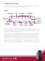
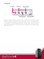
MIDI
Saffire LE operates as a MIDI interface with one input and one output. A MIDI controller keyboard or similar
device can be connected to the MIDI In, whilst a rack synth or multiple instruments (via a MIDI splitter) can
be connected to the MIDI Out using standard MIDI cables, as follows:
MIDI receiving device
MIDI Out
(SuperNova II Rack - not included)
MIDI In
To Mac
or PC
2 way
MIDI traffic
MIDI Transmitting device
(Novation ReMOTE 25 - not included)
Saffire LE can operate in one of two possible MIDI modes. The state of the MIDI THRU switch in
SaffireControl LE determines which MIDI mode will be used, as follows:
Normal MIDI Mode (switch inactive)
This mode should be used when wanting to send MIDI signals from a controller keyboard to the sequencer,
from where MIDI data can also be sent to any external devices, if required. This mode is necessary when the
sequencer is running, because it will prevent doubling of notes that occur when the same MIDI information
is transmitted by both the input device and the sequencer.
MIDI THRU Mode (switch active)
In this mode, all MIDI data received at Saffire LE’s MIDI In is routed directly to the MIDI Out. This mode
is designed for simply passing MIDI through Saffire LE. This may be useful when no sequencer is running,
because you don t need to route MIDI data in and out of you Mac or PC..
n
Saffire Plug-in Suite
Saffire LE comes free with the suite of Saffire plug-ins, provided in VST/AU format for use in the mix.
EQ, Compression, Reverb and Amp Simulation are all available.
n
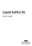
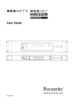
EQ
EQ On/Off switch
(illuminated when active);
use to bypass the EQ
Template
Select slider
Dials adjust the level
of the four bands preset
in each Template
EQ mode select; choose
between Template and
Advanced modes
Fader and Meter for
adjusting and viewing
the level of the signal
at the EQ Input
Switches select Band 1
as a peak/notch (top),
low-shelf (middle) or
high-pass (bottom) filter
Fader and Meter for
adjusting and viewing
the level of the signal
at the EQ Output
Dial sets the
frequency of
Band 1 (freq of
the high-pass
filter)
Dial sets the
cut/boost of
Band 2 (central
position has no
effect)
Dial sets the
resonance (lowpass filter) or Q
(peak/notch) for
Band 4
Switches select Band
4 as a band-pass
(top), high-shelf
(middle) or low-pass
(bottom) filter
Buttons allow
copying and pasting
of settings to and
from other Saffire
compressors
Equalisation of sound is an essential part of the recording process, necessary to remove or boost various
sections of the audible frequency spectrum. The Saffire EQ is 4-band parametric, with the option of shelving
and high/low-pass on bands 1 and 4, and exhibits the same curves as the classic Focusrite EQ; all that’s
required to sculpt sound with truly professional flair!
The EQ window functions in two modes, template mode and advanced mode. When the EQ window is first
launched, the EQ will be set flat in template mode. To switch to advanced mode, simply press the mode
button on the right of the EQ window just to the left of the OUT fader (as shown in the diagram) that
alternates between the two modes. The LED button on the left activates/bypasses the EQ from within the
plug-in window. A fader at either end controls the gain of the signal before and after EQ, respectively.
In advanced mode, all areas of the four band parametric EQ can be adjusted. When the plug-in is first
launched, the advanced mode will be loaded but set flat, i.e. with no gain increase or decrease at any stage
over the entire frequency range. All four EQ bands have three dials each to adjust the frequency (FREQ),
n
EQ (continued)
Gain and Q of the EQ band. Rotating the dials clockwise will increase the value in each case, the exact
numerical value being displayed in a box below the dial whilst rotating and when the mouse cursor moves
over it. The outer two bands controlled by each set of three dials on either end of the panel can be
independently set to be band pass (as default), high/low shelf (middle button) or high/low-pass (bottom
button) by pressing the corresponding small buttons at either end as shown in the diagram. When in
high/low shelf mode, only the GAIN and FREQ dials will be active for that band, and when in high/low-pass
mode, only the FREQ and Q dial will be active to select the cut-off frequency and resonance of the filter. For
example, if wanting to set up a low shelf to increase the bass, press the middle button on the left (Band 1)
and then rotate the GAIN dial on the first band (on the left) clockwise. If wanting to insert a low-pass filter in
the signal path to cut out high frequencies, press the bottom button on the right (Band 4) and then rotate the
FREQ dial on the last band (on the right) to set the cut-off frequency for the filter (above which all
frequencies will not be heard).
In template mode, the slider is used to select a different preset EQ configuration, such as one ideally suited
to recording vocals, guitar, percussion and so on. Click on the desired slider position and the slider will jump
to it. (These templates have configured the EQ controls for all four bands available within the advanced mode
{the lower controls} so that the dials above control the main sonic characteristics of the source being
recorded). For example, with the slider in the Vocal position, the four knobs in template mode relate to the
warmth, presence, harshness and breathiness respectively. Rotating the knobs in a clockwise direction
increases the amount of this property. This does not necessarily mean just increasing the gain of that EQ
band but could be both the gain and Q for instance.
If wanting to set up your own EQ settings starting with a particular template, simply click the mode button
to switch to advanced mode and adjust the controls as detailed above.
Two buttons in the bottom right of the EQ window allow copying and pasting of EQ settings to and from
other instances of the Saffire EQ.
n
Compression
Compressor On/Off switch
(illuminated when active);
use to bypass Compressor
Compressor Mode
Template Defines the amount
Select; choose
select slider of compression in between Advanced
template mode
and Template Mode
Fader and Meter to adjust
the level of the signal at
the Compressor Output
Fader and Meter to
adjust the level of
the signal at the
compressor input
Buttons allow
copying and pasting
of settings to and
from other Saffire
compressors
Dial sets the
Threshold of the
compressor
Dial sets the
Ratio of the
compressor
Dial sets the
Attack time of
the compressor
Dial sets the
Release time
of the
compressor
Dial sets the
Makeup Gain of
the compressor
Meter shows the
amount of gain
reduction caused by
the compressor
The Saffire Compressor plug-in is modelled on the legendary Focusrite hardware devices, with individually
tuned optos to help create the sound of vintage 1960s compression. The plug-in can be used to squash the
dynamics of a sound in varying degrees, e.g. remove the sudden loud bursts, so that the overall level can
then be turned up to make the signal as loud as possible. A compressor essentially acts like an automatic
volume control, turning down the volume of a signal if it gets too loud. This reduces variation between loud
and quiet passages, as it automatically reduces the gain when the signal exceeds a given volume, defined
as the threshold. Using the Saffire Compressor helps to ‘even out’ a performance, stopping a signal from
clipping and/or disappearing in the mix, and can also give it a whole new sonic character.
The Compressor window functions in two modes, template mode and advanced mode. When the window
is first launched, the Compressor will be switched off and set flat in template mode. To switch to advanced
mode, simply press the mode button on the right of the Compressor window just to the left of the OUT fader
(as shown in the diagram) that alternates between the two modes. The LED button on the left
activates/bypasses the Compressor from within the plug-in window. Two faders at either end control the
gain of the signal before and after compression.
In advanced mode, the full range of standard compressor controls are available. The first dial to set is the
threshold (THRESH), which sets the level at which compression begins. The lower this value is set, the
more of the signal will be compressed as the audio will compress when the threshold is reached. Rotate
the THRESH dial anticlockwise to lower the threshold and so increase the compression.
Set the RATIO next, as this determines how much the signal is reduced by when it exceeds the threshold.
For example, a ratio of 10:1 means that when the level of the uncompressed signal exceeds the threshold by
10dB, the compressed signal will only increase by 1dB. The higher the ratio therefore (the further the dial is
n
Compression (continued)
rotated in a clockwise direction) the more heavily the signal is compressed. The next dials to set are the
ATTACK and RELEASE times of the compressor, fastest/shortest position being fully anticlockwise and
slowest/longest being fully clockwise. The ATTACK time defines how quickly the compressor kicks in, e.g.
how fast the signal is turned down when it exceeds the threshold. In other words, setting a slower/longer
attack time by rotating the dial clockwise will mean more of the loud part of the signal gets through
uncompressed, which makes the signal much more punchy but also more likely to clip. The RELEASE time
defines how quickly the compressor stops acting on the signal after it has begun to compress. Setting a
quicker/shorter release time by rotating the dial anticlockwise will normally make the signal louder overall,
however this is dependant on how often the level exceeds the threshold and how fast the attack time is.
Last but not least, the GAIN dial defines how much the level of the compressed signal is increased after
compression. This means that a heavily compressed signal can be turned up loud to give it much more
presence without fear of any overload or clipping occurring. The Gain Reduction (GR) vertical meter to the
right of the plug-in window indicates the amount of compression taking place, which provides a visible
means of determining the Compressor’s effect. All dials have a surrounding blue line to show their value,
with the exact numerical amount displayed whilst rotating and when the mouse cursor moves over the dial.
For those new to compression and wanting to hear its effect in the most obvious way, turn the THRESH down
low and the RATIO up high, then set the ATTACK dial fully anti-clockwise and the RELEASE to a fairly low
value also. Now experiment with the parameters, adjusting the attack time and so on, to see how this
affects the sound. Two buttons in the bottom right of the Compressor window allow copying and pasting of
Compressor settings to and from other instances of the Saffire Compressor.
n
Reverb
Dial sets the amount
of reverberation
Dial sets the size of the
reverberant space
Dial sets the tone (amount
of high and low frequency)
of the reverberation
Dial sets the absorption of the
reverberant space, decreasing
when rotating clockwise
Switches allow the copying and
pasting of settings to and from
other Saffire Reverbs
The reverb settings are defined by three dials. The first dial sets the AMOUNT of reverb, whilst the second
dial defines the SIZE of the reverberant space, both rotating clockwise to increase. The third dial, labelled
DIFFUSION, modifies the absorption of the reverb, rotating clockwise to decrease (increasing the amount of
reflected sound). The fourth dial, labelled TONE, filters the reverberant sound to create more low frequency
(in the fully anticlockwise position) and more high frequency (in the fully clockwise position). The smaller
button to the left of the dials has the same function as with the other plug-ins, to activate/bypass the plug-in
(illuminated when active).
n
Amp Sim
Amp selection slider;
simply click on the desired
simulation name
DRIVE knob allows Amp
distortion to be increased
Additional output
fader to adjust
level of Output
Amp Sim
On/Off switch
Buttons allow
copying and pasting
of settings to and from
other Saffire Amp Sims
Low
Frequency
adjust
Mid
Frequency
adjust
High
Frequency
adjust
Meter displays
output level
The Amp Sim plug-in is designed to allow high quality tracking of guitar parts without the need for a
whole host of physical amplifiers.
The Amp Sim window has an LED button on the left to activate/bypass the amp simulation. When the window
is first launched, the button will be illuminated to show that the plug-in is active; click the button to bypass
as required. A slider is featured to allow different classic amplifier simulations to be selected. Simply click
on an area of the slider to select an amplifier, the slider will jump to whatever area is clicked.
Four dials are included to allow control over the amp’s settings. The first is DRIVE, which increases the level
of distortion when rotated clockwise. The next three are for adjusting the EQ of the amp sim; rotating the
dials clockwise increases the gain of the LOW, MID and HIGH frequency bands respectively from left to right.
The levels of all dials are indicated by the blue surrounding lines, with precise numerical values shown while
rotating or while the mouse cursor passes each dial.
Two buttons in the bottom right of the Amp Sim window allow copying and pasting of Amp Sim settings to
and from other intances of the Saffire Amp Sim.
n
Troubleshooting
LEDs on the Saffire LE hardware aren’t working
• Does the unit have power? This is supplied by the Firewire cable, is one connected? If connecting to a
4-pin Firewire port, is the external PSU connected?
Saffire LE is not recognised as a valid audio interface by the recording software in use (e.g. Ableton)
• Is the hardware connected to the computer over Firewire?
• If using a PC, have the ASIO/WDM drivers been correctly installed from the accompanying DVD?
No signal when using mic inputs
• Is the unit powered correctly? See above.
• Is the gain dial of the corresponding input on the hardware set sufficiently high? Rotate clockwise to
increase the level.
• Is something connected to the corresponding line input on the hardware? This will deactivate the mic input.
• For microphones that require phantom power (e.g. condenser mics), is the +48V switch on the front panel
engaged? (If you are unsure about whether your microphone requires phantom power, check the user
guide for your microphone.)
• If seeing but not hearing a level, is the slider for the monitoring pair of outputs far enough to the left
(towards the INPUT MIX position)? If over to the right (in the P/BACK position), only the tracks from the
sequencer will be heard.
No signal when using line inputs 1 and 2
• Is the unit powered correctly? See above.
• Is the gain dial of the corresponding input on the hardware set sufficiently high? Rotate clockwise to
increase the level.
• Is the Line/Inst switch on the hardware set correctly? The LINE LED must be active.
• If seeing but not hearing a level, is the slider for the monitoring pair of outputs far enough to the left
(towards the INPUT MIX position)? If over to the right (in the P/BACK position), only the tracks from the
sequencer will be heard.
No signal when plugging an instrument into line inputs 1 and 2
• Is the unit powered correctly? See above.
• Is the gain dial of the corresponding input on the hardware set sufficiently high? Rotate clockwise to
increase the level.
• Is the Line/Inst switch on the hardware set correctly? The INST LED must be active.
• If seeing but not hearing a level, is the slider for the monitoring pair of outputs far enough to the left
(towards the INPUT MIX position)? If over to the right (in the P/BACK position), only the tracks from the
sequencer will be heard.
No signal when using Line Inputs 3 and 4
• Is the level on the sending device or instrument high enough?
• If using an Instrument (Guitar or Bass plugged in directly), is the corresponding High Gain switch on
the left of the SaffireControl GUI active?
• If seeing but not hearing a level, is the slider for the monitoring pair of outputs far enough to the left
(towards the INPUT MIX position)? If over to the right (in the P/BACK position), only the tracks from
the sequencer will be heard.
n
Troubleshooting (continued)
No signal heard on the Monitors
• Is the level of the Monitors turned up within SaffireControl LE and the Mute switch inactive?
• Is the MONITOR dial on the hardware set sufficiently high.
• Are the mix controls (Input Mix faders, S/W (Playback) faders and INPUT MIX-P/BACK MIX slider) set
correctly? If you are attempting to play back tracks from the sequencer and the slider is in the extreme
left position (just INPUT MIX) then no Playback Tracks will be heard.
No Playback tracks heard on Monitors/Headphones
• Is the INPUT MIX-P/BACK MIX slider for the Monitors/Headphones set far enough to the right, towards
the P/BACK MIX end? If not, only the INPUT MIX will be heard.
• Do the tracks within the sequencer have sufficient level? The level set by the faders on the right of the
SaffireControl LE window are respective to that set within the sequencer.
• Are the S/W faders that audio is routed to in the sequencer set correctly in SaffireControl LE? If you have
routed all tracks to Saffire LE Outputs 5/6 and 7/8 and S/W faders 5/6 and 7/8 are down for the monitoring
outputs, no signal will be heard.
Cannot set a sample rate
• Is Saffire LE being used to record audio? Whilst audio is being recorded, IN USE will show and the sample
rate cannot be selected.
Cannot lock to an external device
• Is a valid S/PDIF source connected to the S/PDIF Input on the rear panel?
• Is Saffire LE set to the same sample rate as the digital audio received at the S/PDIF In? If not, a Lock
cannot be achieved.
• Are you using a Mac rather than a PC? You could be experiencing a core audio driver problem. Check the
Apple website for core audio driver updates or consult the Focusrite online answerbase.
The Compressor is not working
• Is the plug-in active? The small switch on the left of the plug-in window must be illuminated.
• Are the compressor controls set correctly? The threshold must be low enough for the signal to exceed it
for the compressor to have any effect.
The EQ is not working
• Is the plug-in active? The small switch on the left of the plug-in window must be illuminated.
• Are the EQ controls in a position to have an effect on frequencies that are present in the signal?
For example, a low-pass filter working on the upper frequencies will have little effect on a bass part.
The Reverb is not working
• Is the AMOUNT dial set sufficiently high? If not, no reverb will be added.
• Is the TONE control set to an extreme position in the plug-in window?
For more technical support, visit the online ANSWERBASE @ www.focusrite.com
n
Specifications
MIC
• Frequency Response: 20Hz - 20kHz +/- 0.1 dB
• THD+N: 0.001% (measured at 1kHz with a 20Hz/22kHz bandpass filter)
• Noise: EIN > 120dB (measured at 60dB of gain with 150 Ohm termination (20Hz/22kHz bandpass filter)
LINE
• Frequency Response: 20Hz - 20kHz +/- 0.1dB
• THD+N: 0.001% (measured with 0dBFS input and 22Hz/22kHz bandpass filter)
• Noise: -88dBu (22Hz/22kHz bandpass filter)
INSTRUMENT
• Frequency Response: 20Hz - 20kHz +/- 0.1dB
• THD+N: 0.004% (measured with 0dBu input and 20Hz/22kHz bandpass filter)
• Noise: -87dBu (20Hz/22kHz bandpass filter)
DIGITAL PERFORMANCE
• Clock Source: Internal clock or sync to word clock on SPDIF
• A/D Dynamic Range 104dB 'A-weighted' (Inputs 1+2)
• A/D Dynamic Range 106dB 'A-weighted' (Inputs 3+4)
• D/A Dynamic Range > 105dB ‘A-weighted' (all outputs)
• Clock Jitter < 250 pico seconds
• Sample rate 44.1 to 96kHz
WEIGHT and DIMS
• 1.1kg - 6.5cm x 17cm x 17cm
ANALOGUE INPUTS
• Mic: 2 x XLR on front panel
• Mic Gain: +13dB to + 60dB
• Line 1&2: 2 x 1/4” TRS Jack (front panel)
• Line 1&2 Gain: -10dB to +36dB
• Instrument: As above, switched to Instrument
• Instrument Gain: +13dB to +60dB
• Line 3&4: 2 x 1/4” TRS Jack (rear panel)
• Line 3&4 Gain: +16dBu or –10dBV for full scale input (software switchable)
ANALOGUE OUTPUTS
• Line level 6 x 1/4” TRS Jack
• Nominal output level 0dBFS = 16dBu, balanced
• Frequency Response: 20Hz – 20kHz +/- 0.2dB
• THD+N <0.0014% (measured with 0dBFS input 22Hz/22kHz bandpass filter)
• Front Panel Analogue Volume control for outputs 1&2
• Software Digital Volume control for outputs 3-6
All outputs are useable as monitoring outputs
n
Specifications (continued)
DIGITAL I/O
• 2 x SPDIF (RCA phono) on rear panel (24-bit, 96kHz) Output transformer isolated
MIDI I/O
• 1 in / 1 out on rear panel
FIREWIRE S400
• 2 ports
POWER
• Either via FIREWIRE or external PSU (included)
HEADPHONE MONITORING
• 1 x 1/4” TRS Jack on front panel (mirrors outputs 3-4)
• High power headphone driver
n
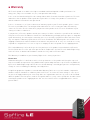
Warranty
All Focusrite products are built to the highest standards and should provide reliable performance for
many years, subject to reasonable care, use, transportation and storage.
In the event of a Manufacturing Defect becoming evident within 12 months from date of purchase Focusrite
undertakes that the product will be repaired or replaced free of charge if the product is returned to the
authorised dealer from whom it was purchased.
In these circumstances, or if you need an out-of-warranty repair to your Focusrite product, please contact
Focusrite at: [email protected] and you will be advised of the correct return procedure. Alternatively
contact the Focusrite Reseller from which you purchased the product or the Focusrite Distributor in your
country of residence or business.
If you purchase a Focusrite product outside your country of residence or business you will not be entitled to
ask your local Focusrite Distributor to honour this Limited Warranty, although you may request a chargeable
repair. Alternatively, the unit may be returned at your cost to the dealer you purchased the unit from so that
they can organise a Warranty repair with their Focusrite Distributor. This Warranty does not include cost of
shipping to and from the authorised dealer from whom it was purchased. In every case it will be necessary
to provide the original invoice or store receipt to accompany the defective product to the supplying dealer.
This Limited Warranty is offered solely to the first purchaser of the product from an Authorised Focusrite
Reseller (defined as a reseller which has purchased the Product directly from Focusrite Audio Engineering
Ltd. in the UK or its Authorised Distributors outside the U.K,) and is not transferable.
This Warranty is in addition to your Statutory Rights in the country of purchase.
Please note:
A Manufacturing Defect is defined as a defect in the performance of the product which may be expected
from a reasonable interpretation of the published description and performance specifications as published
by Focusrite Audio Engineering Ltd. This does not include damage caused by post-purchase transportation,
storage or careless handling, nor damage caused by misuse.
A significant proportion of products returned under Warranty (which are very few in number compared to
numbers sold) are found not to exhibit any fault at all. Please check that the mains voltage is correctly set
for your local supply and that your connecting cables are in good order and correctly connected. If in doubt
about the product functions please read the user guide and if necessary contact your dealer for advice before
returning the product to the supplying dealer. You can also email Focusrite at [email protected] for
general advice.
n
Accuracy
Whilst every effort has been made to ensure the accuracy and content of this manual, Focusrite Audio
Engineering Ltd makes no representations or warranties regarding the contents.
n
Copyright
Copyright 2005 Focusrite Audio Engineering Ltd. All rights reserved. No part of this manual may be
reproduced, photocopied, stored on a retrieval system, transmitted or passed to a third party by any
means or in any form without the express prior consent of Focusrite Audio Engineering Ltd.
E and OE