1
AUTOMATION TECHNOLOGY GROUP
MOTION TECHNOLOGY DIVISION
110 Fordham Road
Wilmington, MA 01887
(978) 988-9800
Fax (978) 988-9940
Part# 903-524000-02
List Price $25 U.S.
May 31, 1994
Rev C
5240/5220
Stepper/Motor Indexer/Driver
Programming Reference Manual
Rev C
T.....................................................
able of Contents
1 Introduction to 5240 Programming
1.1
1.1 RS-232 Serial Port . . . . . . . . . . . . . . . . . . . . . . . . . . . . . 1.1
1.2 Modes of Operation . . . . . . . . . . . . . . . . . . . . . . . . . . . . 1.3
1.2.1 Immediate Mode . . . . . . . . . . . . . . . . . . . . . . . . . . 1.3
1.2.2 Program Execution Mode and Edit Mode . . . . . . . . . . . . . 1.5
1.3 Abort Commands . . . . . . . . . . . . . . . . . . . . . . . . . . . . . 1.6
1.3.1 ESCape . . . . . . . . . . . . . . . . . . . . . . . . . . . . . . . 1.7
1.3.2 ”S” or ”s” . . . . . . . . . . . . . . . . . . . . . . . . . . . . . . 1.7
1.3.3 Remote Stop . . . . . . . . . . . . . . . . . . . . . . . . . . . . . 1.8
1.4 Jog Inputs . . . . . . . . . . . . . . . . . . . . . . . . . . . . . . . . . 1.8
1.5 5240 Start Up . . . . . . . . . . . . . . . . . . . . . . . . . . . . . . . 1.9
1.5.1 Single-Axis Start Up . . . . . . . . . . . . . . . . . . . . . . . . 1.9
1.5.2 Multi-Axis Start Up . . . . . . . . . . . . . . . . . . . . . . . . . 1.10
2 Quick Reference
3 5240 Programming Instructions
Appendix A: ASCII Codes
Appendix B: Terminal Program Example
Appendix C: Non-Volatile Memory
Appendix D: High Speed Considerations
Appendix E: Ramp Algorithm & Lookup Table
Appendix F: Daisy-Chain Input Commands
Appendix G: Command Summary
Index
5240/ 5220 Pro g ra m m ing Re fe re nc e M a nua l - Re v C
2.1
3.1
A-1
B-1
C-1
D-1
E-1
F-1
G-1
1 Introduc tion to 5240
Progra mming
In this
Chapter
This chapter contains informations necessary to become familiar
with the 5240 programming environment. Topics covered are:
•
RS-232 serial port
•
Modes of operation
•
Abort commands
•
5240 Start up
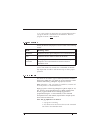
1.1 RS-232 Se ria l Po rt
The 5240 indexer/driver may be interfaced to the RS232 port of a
terminal or PC. Baud rates of 300 through 9600 are selectable by
asserting combinations of plug-in jumpers.
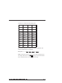
Jumpers E16, E17, and E18 are used to set baud rates as shown
in the table below. The cover must be removed for access. Refer
to Section 2.6 of your Installation and Hardware Manual for the
location of these jumpers and instructions for removing the cover.
Baud Rate
E16
E17
E18
9600
L-C
L-C
L-C
4800
H-C
L-C
L-C
2400
L-C
H-C
L-C
1800
H-C
H-C
L-C
1200
L-C
L-C
H-C
600
H-C
L-C
H-C
300
L-C
H-C
H-C
Illegal
H-C
H-C
H-C
Notes:
1. The factory default setting is 9600 baud.
5240/ 5220 Pro g ra m m ing Re fe re nc e M a nua l - Re v C
1-1
2. The 5240 tests the state of these jumpers at
power-up. Therefore, they have no effect until power is
cycled.
Procedure
Connect the 5240 to your terminal or host computer as shown in
Section 2.5.3, “J2 Serial Port Connection”, of the 5240
Installation and Hardware Reference portion of this manual.
If you are using a PC or compatible, use the PACCOM disk
supplied with your 5240 to emulate a terminal.
1. Insert the PACCOM diskette into the PC and select that drive
(usually A: or B:).
2. Type “PACCOM<ENTER>” to start PACCOM.
3. On PACCOM’s main menu, use the arrow keys to highlight
“Select Hardware” and press <ENTER>.
4. Select “5220/5240 Series” and press <ENTER>.
5. Press <Esc> to return to the main menu. Now select
“Terminal Emulator” and press <ENTER>.
Note: The PC is now acting as a “dumb” terminal.
To verify communication with your 5240, apply power to the
5240 and press the space bar twice. You should see the message:
Sigma Products/Pacific Scientific
285-1 v1.06 23
If you do not get this message, remove power from the 5240 and:
1. Check all the cabling.
2. Check that:
a. The terminal and baud rates are the same.
b. The correct COM port is selected.
c. The following parameters are met:
Parity: None
Stop Bits: One
Data Bits: Eight
1-2
5240/ 5220 Pro g ra m m ing Re fe re nc e M a nua l - Re v C
Note: The terminal’s serial port parameters can be set using
PACCOM’s “Init Serial Port” function.
1.2 M o d e s o f O p e ra tio n
The 5240 Indexer/Driver can be operated in three modes:
•
Immediate
•
Program execution
•
Edit
1.2.1 Im m e d ia te M o d e
In the immediate mode, commands are loaded via the RS-232
port and executed upon receipt of a carriage return. 1 When AC
power is applied, the 5240 will enter the immediate mode after:
1. Receiving an Esc character. The 5240 will then send the #
character, followed by a carriage-return/line-feed to the
terminal.
or
2. Receiving two space characters. The 5240 will then send the
sign-on message described in Section 1.1 “RS-232 Serial
Port.”
Note: This is true unless the “Remote Start” Input (J1-9) is
pulsed or held low which would force the 5240 to enter the
program execution mode.
For example, the following sequence will cause the 5240 to
perform a 1000 step incremental move in the clockwise direction:
1. Apply power to the 5240.
2. Press the Esc key on the terminal. The 5240 will enter the
immediate mode and send the # character, followed by
carriage-return/line-feed to the terminal.
1
Multiple 5240s can be daisy chained so that a single terminal can be used to
communicate with several axes. The command format is slightly different than the
single axis format described here and is covered in Section 1.5.2 and Appendix F.
5240/ 5220 Pro g ra m m ing Re fe re nc e M a nua l - Re v C
1-3
3. Type the following:
+1000<ENTER>
The 5240 will initiate a 1000 step incremental move. Parameters
such as ramp rate and speed will be at the power-on default
values set at the factory unless you have changed them using the
“P” command described later.
Immediate
mode
guidelines
•
A command can be changed prior to entry by using the
Backspace key.
•
Command lines may be up to 11 characters long, including
the carriage-return. Only one command can be included on
the line.
•
Spaces are optional between command characters and the
first number. Commands with two numbers require at least
one space between numbers.
•
Command characters may be either upper case or lower case.
•
The 5240 echoes characters until a carriage-return is
received.2 When a carriage return is received (signaling the
end of a command) the 5240 normally sends a
carriage-return/line-feed as soon as action is taken on the
command3 unless the command is a request for data. If the
command is a request for data (such as query), the 5240
sends the requested data followed by a
carriage-return/line-feed.
•
If a non-motion command (such as setting an output discreet)
is sent to the controller while a motion command (such as an
2
If more than 11 characters are received before a carriage-return, then the 5240
sends the character #, followed by a carriage-return/line-feed indicating too long a
line.
3
The carriage-return/line-feed does not mean execution of the command is
complete, only that execution of the command has begun. For example, for a long
incremental move, carriage-return/line-feed is sent as soon as the move starts.
1-4
5240/ 5220 Pro g ra m m ing Re fe re nc e M a nua l - Re v C
index move) is being executed, the non-motion command
will be executed as soon as it is received.
•
If a second motion command is sent to the controller while
another is in process, the first will run to completion before
the second is executed. The 5240 will not send a
carriage-return/line-feed following the receipt of the second
command until the first is complete because no action is
taken on the second command until then. No additional
commands can be sent to the 5240 until it sends the
carriage-return/line-feed.
The 5240 will not respond to immediate commands if either the
Jog+ or Jog- inputs are active prior to the sending of the first
character of a command line. Conversely, once the first character
of a command line is transmitted to the 5240, the Jog+ and Joginputs are ignored.
1.2.2 Pro g ra m Exe c utio n M o d e a nd Ed it M o d e
In program execution mode, commands stored in non-volatile
(NV) memory are executed sequentially. Jump and looping
instructions, which can be conditional on the state of the inputs,
allow complex motion profiles.
A program is created by typing “Enn”<ENTER> while in the
immediate mode. This exits the immediate mode and enters the
edit mode at line nn. For example, typing “E0” <ENTER> allows
entering line 0 of the program.
Pressing <ENTER> stores the command line. The 5240 will then
send the line number for the next command to the terminal and
the next command can be typed.
The edit mode is terminated, and the immediate mode entered by
typing “E”<ENTER> or by pressing the Esc key. Typing
“E”<ENTER> causes the 5240 to put and “End” symbol after the
last line so that program execution will terminate after that line.
Pressing <Esc> will exit the edit mode without the “End”
symbol. Therefore, to modify a line of a program already in
memory, enter the edit mode by typing “Enn” where nn is the
desired line number, retype the line followed by <ENTER>, and
exit the edit mode by pressing <Esc>.
5240/ 5220 Pro g ra m m ing Re fe re nc e M a nua l - Re v C
1-5
A program can be run by typing “Gnn”<ENTER> while in the
immediate mode where nn is the first line number of your
program.
Program
execution
mode and
edit mode
guidelines
Below are some specific guidelines to be followed while in the
program execution mode and edit mode.
•
One command can be entered per program line.
•
If a program begins at line 0 (using E00), it can be started by
typing “G”<ENTER> or by pulling the Remote Start input
(J1-9) low.
•
Program execution as well as motor motion can always be
stopped by pressing the <Esc> key.
•
Several non-overlapping programs can reside in memory at
the same time, each starting at different line numbers.
•
Program memory can be read using the list from Address
Command (L).
•
The TRACE feature displays the instruction being executed
while a program is running which is useful for program
debugging. See the “G aa b” Command for more information.
1.3 A b o rt C o m m a nd s
The following commands abort an operation in process:
1-6
•
ESCape
•
“S”
•
Remote stop
5240/ 5220 Pro g ra m m ing Re fe re nc e M a nua l - Re v C
1.3.1 ESC a p e
Sending the ESC character (CHR$(27)) to the indexer over the
RS-232 port results in the following actions:
Mode
Resulting Action
Immediate
Clears input buffer and terminates all motion. Step output is
terminated immediately (no ramping).
Edit
Exit edit mode and return to immediate mode without
inserting “END” in program.
Program
Execution
Aborts program execution and terminates all motion. Step
output is terminated immediately (no ramping). Indexer
returns to immediate mode.
Note: If more than one process is active when an ESCape
command is issued, ALL processes are aborted.
1.3.2 S o r s
Sending “S” (a following carriage-return is required when indexer
is in immediate mode) to the indexer over the RS-232 port results
in the following actions:
Mode
Resulting Action
Immediate
Terminates motion. Speed ramped to zero at deceleration rate.
Edit
Enters “S” in program line. No effect on any motion in
progress.
Program
Execution
Aborts program execution and terminates all motion. Speed
ramped to zero at deceleration rate. Indexer returns to
immediate mode.
Note: 1. Sending “S”<CR> does not terminate motion properly
in the immediate mode when one motion command is in process
and another has already been commanded. In this case, ESC
should be used to terminate motion.
5240/ 5220 Pro g ra m m ing Re fe re nc e M a nua l - Re v C
1-7
2.“S” can be used as an instruction in a program. When used in
a program, motion is terminated as described here. However,
program execution is not terminated.
1.3.3 Re m o te Sto p
Forcing the Remote Stop Input (J1-8) low results in the following
actions:
Mode
Resulting Action
Immediate
Terminates motion. Speed ramped to zero at deceleration rate.
Edit
Terminates motion. Indexer remains in edit mode.
Program
Execution
Aborts program execution and terminates all motion. Speed
ramped to zero at deceleration rate. Indexer returns to
immediate mode.
Note: If in the immediate mode and one motion command is in
process and another has already been commanded, the Remote
Stop Input must be held low until motion stops to insure proper
operation.
1.4 Jo g Inp uts
The motor can be made to jog at constant speed in the clockwise
direction by pulling the + Jog Input (J1-25 low and in the counter
clockwise direction by pulling the -Jog Input (J1-24) low.
Note: If both the + and - Jog inputs are pulled low, rotation will
be in the positive or clockwise direction.
High jog speed is selected by pulling the Jog Hi/Lo Input (J1-10)
low. Leaving (J1-10) disconnected or by pulling it high selects
the low jog speed. Both the low and high jog speeds are
programmed using the ^11 hh command (see the command
descriptions later in this manual). Speed will be ramped up and
down at the accel/decel rate.
Note: The jog inputs have no effect if:
1. A program is executing.
2. Any character has been entered to start the command
line while in the immediate mode.
1-8
5240/ 5220 Pro g ra m m ing Re fe re nc e M a nua l - Re v C
3. A positioning move is in process while in immediate
mode. (A ramp to Velocity command will be overridden
by a jog command.).
1.5 5240 Sta rt Up
This section explains the two kinds of 5240 start up. These are:
•
Single-axis
•
Multi-axis
1.5.1 Sing le -A xis Sta rt Up
The start up sequence for single axis units consists of two
consecutive space characters. The result is a pre-defined sign on
message:
Sigma Products/Pacific Scientific
285-1 v1.06 23
The 5240 Indexer/Driver is now in the immediate mode.
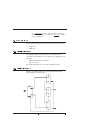
1.5.2 M ulti-A xis Sta rt Up
Multiple 5240 indexer/drivers can be interconnected directly
(daisy-chained) as shown below.
5240/ 5220 Pro g ra m m ing Re fe re nc e M a nua l - Re v C
1-9
Note: All 5240 baud settings must be the same.
Connection
diagram
Procedure
The start up sequence for multi-axis operation requires
transmitting the Line Feed Character (^J) to the first axis
followed by a valid “Name” character that must be a, b, ...z or A,
B, ....Z (names are case sensitive).
The first axis adopts this character as its name and sends the next
highest ASCII character to the next axis and so on. Thus, if the
host sends ^J “A” to the first axis after power-up, the first axis
will adopt the name A, the second B, the third C, etc.
Once this start up sequence is complete, each axis echoes
received characters to the next axis in the daisy chain. A
command can be sent from the host to a particular axis by
sending the command:
Name Command ^J
If the third axis in the string has the name C, sending the
command:
C R 1000^J
results in the third axis ramping up to 1000 steps/sec.
The ESCape command does not need a prefix and will abort
motion and programs in all axes.
Notes:
1. Once the recognized sequence is received, the 5240 will
assume the name until a hardware reset is made.
2. In multi-axis configuration, sign-on messages will not be
generated.
3. Refer to Appendix F, “Daisy Chain Input Commands” for
additional information on multi-axis execution.
1-10
5240/ 5220 Pro g ra m m ing Re fe re nc e M a nua l - Re v C
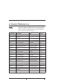
2 Quic k Re fe re nc e
In this
Cha pte r
This section contains an alphabetized list of 5240 programming
commands including a brief description and the operating modes
where they apply. Detailed descriptions of each command is
given on the page indicated in Chapter 3.
Command
Description
Mode
Page #
A 1 and A
All clear/restore
Immediate
3-2
B
Not used
Cn
Current enable
Immediate/Program
3-3
D
Not used
E aa
Edit from address
Immediate
3-5
F nn
Start/Stop velocity
Immediate/Program
3-6
G aa b
Go from address/trace
Immediate/Program
3-8
Hs d
Home
Immediate/Program
3-10
I
Not used
J aa n
Jump to address
Program
3-12
K
Read input port
Immediate/program
3-13
L aa
List from address
Immediate
3-16
Mn
Accel/Decel slope
Immediate/Program
3-17
N
Not used
Op
Distance event
Immediate/Program
3-19
P
Parameters store
Immediate
3-21
Qn
Query
Immediate
3-22
R nn
Ramp to velocity
Immediate/Program
3-24
S
Stop
Immediate/Program
3-26
T
Not used
U aa k
Loop on input port
Program
3-27
5240/ 5220 Pro g ra m m ing Re fe re nc e M a nua l - Re v C
2 - 1
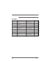
Ta ble (c ontd)
Command
Description
Mode
Page #
V nn
Velocity
Immediate/Program
3-29
W nn
Wait
Program
3-30
X
Not used
Yn
Set output port
Immediate/Program
3-31
Zp
Set position counter
Immediate/Program
3-33
.
Hold and wait
Immediate/Program
3-34
+ nn
Positive incremental move
Immediate/Program
3-36
- nn
Negative incremental move
Immediate/Program
3-37
@p
Absolute move
Immediate/Program
3-38
^ 11 hh
Jog velocity
Immediate
3-39
\n
Divide
Immediate/Program
3-40
ESC
Abort
Immediate
3-41
2 - 2
5240/ 5220 Pro g ra m m ing Re fe re nc e M a nua l - Re v C
A1 a nd A
All Cle a r / Re store
Im m e d ia te
Purpose
These commands initialize the 5240. The command A1<ENTER>
clears all programs and restores the variables M, F, and V to their
factory default values. The factory default values can not be altered by
the user and are:
M=5
Acceleration/Deceleration Slope
F = 400
Start/stop speed
V = 5009
Final velocity
A <ENTER> sets the values of M, F, and V to the values stored in
non-volatile memory (which can be altered using the “P” command).
Nothing in non-volatile memory is altered by A <ENTER>.
Syntax
A1 <ENTER>
A <ENTER>
Note: Frequent use of the A1 command should be avoided because
lifetime of the non-volatile memory will be reduced. For additional
information, refer to Appendix C, “Non-Volatile Memory.”
Programming
guidelines
To find the active values for M, F, and V, simply type “Q” <ENTER>.
The terminal will display:
Q M = mmm(ssss) F= fff, V= vvvv
where mmm is the value of M, ssss is the corresponding
number of steps to reach the final velocity, fff is the value of
F, and vvvv is the value of V.
3 - 2
5240/ 5220 Pro g ra m m ing Re fe re nc e M a nua l - Re v C
C n
Curre nt Ena ble
Im m e d ia te / Pro g ra m
Purpose
This command enables and disables the driver section of the 5240.
Syntax
C n <ENTER>
C0
Disables driver so no current is applied to the motor
windings. DISABLE red LED will illuminate.
Caution
Care should be practiced when using this command since the motor
shaft will have no holding torque.
C1
Default
Enables driver. C1 forces DISABLE red LED to be
turned OFF.
C1
Note: The user may change the default value by using the “P”
command.
Programming
guidelines
On receipt of any “Move” command, motor phases are enabled
automatically and are energized while stepping. When stepping is
completed a settling time of 255 steps at the initial velocity is provided
before the motor phases (Enable) are automatically de-energized.
5240/ 5220 Pro g ra m m ing Re fe re nc e M a nua l - Re v C
3 - 3
Program
segment
3 - 4
Program line
Explanation
E0
Enter the program block starting at address 0
0 M5
Set ramp factor to 5
2 F 300
Set start/stop speed to 300 sps
5 V 1000
Set final velocity to 1000 sps
8 + 5000
Index 5000 steps in the positive direction
11 W 100
Wait 0.1 second
14 C 0
Disable the driver
E
End of program block terminator
5240/ 5220 Pro g ra m m ing Re fe re nc e M a nua l - Re v C
E aa
Edit from Addre ss
Im m e d ia te
Purpose
This command is used to enter or edit a program.
Syntax
E aa <ENTER>
Range
aa = 0 to 255
Programming
guidelines
If “aa” is left blank, the editing will start from address 0.
Existing programs can be modified by specifying starting address.
ESCape will cause a return to the Immediate mode without inserting
an end of program terminator.
Entering a second “E” command will terminate the program mode and
will insert a program terminator in the stored program followed by a
return to the immediate mode.
Instructions are stored directly in the non-volatile memory after each
line is entered.
Program
segment
Program line
Explanation
E0
Enter the edit mode at address 0
0M5
Set ramp factor to 5
2 F 400
Set start/stop speed to 400 sps
5 V 1200
Set the velocity to 1200 sps
8 - 2500
Index 2500 steps in the negative direction
E
End of program block terminator
Note: For additional information, refer to Appendix B, “Terminal
Program Example”, and Appendix C, “Non-Volatile Memory.”
5240/ 5220 Pro g ra m m ing Re fe re nc e M a nua l - Re v C
3 - 5
F nn
Sta rt/ Stop V e loc ity
Im m e d ia te / Pro g ra m
Purpose
This parameter sets the start/stop velocity (initial velocity) in steps per
second. This is the lowest velocity commanded when ramping the
speed up during acceleration and ramping the speed down during
deceleration.
Syntax
F nn <ENTER>
Default
400 steps/sec
Note: The user may change the default value by using the ”P”
command.
Value
nn = 14 to 2003
Programming
guidelines
As with all velocity parameters, the start/stop speed is divided by the
divide command (\n).
The Query “Q” command can be used to examine and display the
updated velocities.
The start/stop velocity applies to:
•
•
•
•
3 - 6
All positioning commands. (+, -, @p)
Ramp to velocity command. (R)
Software stop (S) and hardware stop input.
Final phase in homing sequence if home speed is above
start/stop speed.
5240/ 5220 Pro g ra m m ing Re fe re nc e M a nua l - Re v C
Program
segment
Program line
Explanation
E0
Enter the program block starting at address 0
0 M5
Set ramp factor to 5
2 F 300
Set Start/stop speed to 300 sps
5 V 1200
Set velocity to 1200 sps
8 - 5000
Index 5000 steps in the negative direction
E
End of program block terminator
Note: For additional information, refer to Appendix D, “High Speed
Considerations”, and Appendix E, “Ramp Algorithm and Lookup
Table”.
5240/ 5220 Pro g ra m m ing Re fe re nc e M a nua l - Re v C
3 - 7
G aa b
G o from A ddre ss, Tra c e
Im m e d ia te / Pro g ra m
Purpose
This command will execute the programmed sequence starting at
location “aa”.
Most programs will begin at “0”. However, the user may wish to start
at another address. The address must begin at a stored instruction
address.
Syntax
G aa b <ENTER>
If b = 1, the trace mode is turned on. A display of the current step
being executed is produced while the program is running.
Programming
guidelines
The format of the displayed program lines is the same as that of the
“L” command.
The Trace mode will be in effect until the program ends or is aborted.
The Trace mode is useful in developing or debugging programs.
3 - 8
5240/ 5220 Pro g ra m m ing Re fe re nc e M a nua l - Re v C
Program
segment
Program line
Explanation
E0
Enter the program block starting at address 0
0 \5
Set divide factor to 5
2 M 50
Set ramp factor to 50
4 F 1000
Set start/stop speed to 1000 sps
7 V 10000
Set velocity to 10000
10 + 10000
Index 10000 steps in the positive direction
13 S
Stop
14 G 40 1
Go to address 40 and turn trace mode on
E
End of program block terminator
E40
Enter the program block starting at address 40
40 \ 1
Set divide factor to 1
42 M 5
Set ramp factor to 5
44 F 350
Set start/stop speed to 350 sps
47 V 1500
Set velocity to 1500 sps
50 - 5000
Index 5000 steps in the negative direction
53 S
Stop
E
End of program block terminator
Note: For additional information, please refer to Appendix B,
“Terminal Program Example”.
5240/ 5220 Pro g ra m m ing Re fe re nc e M a nua l - Re v C
3 - 9
Hs d
Hom e
Im m e d ia te / Pro g ra m
Purpose
This command initiates a search for the home position. Home position
is defined by the home input (J1-13) transitioning from low to high.
The search algorithm insures that the transition is sensed with the
motor turning in the same direction to eliminate affects of backlash.
Syntax
Hs d <ENTER>
s specifies the speed while searching for the home switch while d
specifies the initial search direction as described below.
Value
s = 1 to 255
Step rate equals ten times s (10 - 2550 steps per second)
d = 0 or 1
d = 0:
If the home input is high, initial rotation will be counter-clockwise at
the speed specified by parameter s. When the home input goes low, the
motor will stop, then reverse direction and rotate clockwise at the start
speed until the home input goes high. This transition defines the home
position and rotation stops.
d = 1:
If the home input is high, initial rotation will be clockwise at the speed
specified by parameter s. When the home input goes low, the motor
will stop, then reverse direction and rotate counterclockwise at the start
speed until the home input goes high. This transition defines the home
position and rotation stops.
Programming
guidelines
3 - 10
As with all velocity parameters, the home search speed is divided by
the divide command (\n).
5240/ 5220 Pro g ra m m ing Re fe re nc e M a nua l - Re v C
Program
segment
Program line
Explanation
E0
Enter the program block starting at address 0
0 M5
Set ramp factor to 5
2 F 300
Set start/stop speed to 300 sps
5 V 100
Set velocity to 100 sps
8 H 50 1
Initiate home routine
10 Z 0
Set position counter to 0
E
End of program block terminator
5240/ 5220 Pro g ra m m ing Re fe re nc e M a nua l - Re v C
3 - 11
J aa n
Jum p to A ddre ss a a , n tim e s
Pro g ra m
Purpose
Executes a program segment n + 1 times.
Syntax
aa Start of program segment
.
.
.
bb J aa n
The above lines cause the program segment starting at line aa to be
executed n + 1 times (once before the jump is executed and n more
times due to the n jumps).
Values
aa must be a valid program number
n = 0 to 255
Programming
guidelines
This instruction cannot be nested because there is only one jump
counter available for use at a given time.
Program
segment
Program line
3 - 12
Explanation
E0
Enter the program block starting at address 0
0 M5
Set the ramp factor to 5
2 F 300
Set start/stop speed to 300 sps
5 V 1000
Set the velocity to 1000 sps
8 + 200
Index 200 steps in the positive direction
11 W 500
Wait 0.5 seconds
14 J 8 9
Jump to address 8, 9 times (index 200 steps 10
times)
E
End of program block terminator
5240/ 5220 Pro g ra m m ing Re fe re nc e M a nua l - Re v C
K
Re a d I/ O Sta tus
Im m e d ia te / Pro g ra m
Purpose
This command returns a decimal number corresponding to the I/O
Status. The number returned is formed as follows:
N = I/O(1) + 2 * I/O(2) + 4 * I/O(3) + 8 * I/O(4) + 16 * I/O(5) + 32 *
M + 64 * T + 128 * CCW
where
I/O(1) - I/O(5) correspond to the state of the corresponding
programmable input/output ports. I/O(n) is equal to 0 if the port n is
high and the port n output is set equal to 0. I/O(n) is equal to 1 if the
port n input is pulled low or the port n output is set equal to 1.
M equals 1 if the Moving port (J1-22) is low (steps being generated).
Otherwise, M equals 0.
T equals 1 if the Trip output (J1-11) is low and 0 if the Trip output is
high. The Trip output toggles every time the position crosses the value
of the Distance Event parameter (See the O p instruction description).
CCW equals 1 if the active or most recent motion is in the
counterclockwise direction, otherwise CCW equals 0.
Example:
All outputs set to 0
Input 1 is low (1)
Input 2 is high (0)
Input 3 is low (1)
Input 4 is high (0)
Input 5 is low (1)
Moving is 1
T is 0
CCW is 1
The number returned by the K command is:
1 + 0 + 4 + 0 + 16 + 32 + 0 + 128 = 181
5240/ 5220 Pro g ra m m ing Re fe re nc e M a nua l - Re v C
3 - 13
Syntax
K <ENTER>
Value
returned
0 to 255
Programming
guidelines
This command is only used to return I/O port status to the host
terminal since the 5240 has no commands which can use the
information provided.
At hardware reset, all ports (Inputs/Outputs) are high.
Caution
Ports are bi-directional. To avoid confusion it is recommended that
each port be used as an input or an output but not both.
Note: The K and the Y129 commands are equivalent. Both commands
can be used interchangeably to read and display the ports
(inputs/outputs). Refer to the “Y” command for additional information.
Program
segment
Program line
Explanation
E60
Enter the program block at address 60
60 M 5
Set ramp factor to 5
62 F 450
Set start/stop speed to 450 sps
65 V 1500
Set velocity to 1500
68 O- 1000
Set distance event at 1000 steps counterclockwise
71 Z 0
Set the position to 0
74 - 5000
Index 5000 steps in the negative direction
77 K
Return the ports status
E
End of program block terminator
Executing the above program segment returns the data 192 to the
terminal. The value 192 indicates that distance event has passed and
motion is in the negative direction (64 + 128).
3 - 14
5240/ 5220 Pro g ra m m ing Re fe re nc e M a nua l - Re v C
Program
segment
Program line
Explanation
E80
Enter the program block at address 80
80 M 5
Set ramp factor to 5
82 F 450
Set start/stop speed to 450 sps
85 V 1200
Set velocity to 1200 sps
88 Z 0
Set the position counter to 0
91 + 1100
Index 1100 steps in the positive direction
94 Z 0
Set the position counter to 0
97 0 -1000
Set distance event at 1000 steps counterclockwise
100 - 5000
Index 5000 steps in the negative direction
103 Y 129
Return the port status
105 + 5000
Index 5000 steps in the positive direction
108 O 0
Disable the distance event
111 S
Stop
E
End of the program block terminator
Executing the above program returns the data 192 back to the terminal.
The value 192 indicates that distance event has passed and motion is in
the negative direction (64 + 128).
5240/ 5220 Pro g ra m m ing Re fe re nc e M a nua l - Re v C
3 - 15
L aa
List from Addre ss
Im m e d ia te
Purpose
This command lists programs stored in non-volatile memory using the
following format:
Address
Instruction
Value1 Value2
Note: Values will be displayed only if applicable to the particular
instruction type.
Syntax
L aa <ENTER>
Programming
guidelines
A maximum of twenty instructions are displayed (listed) at any time.
Programs will be listed until the “E” (end of program) character is
encountered. To list a program starting at a higher address, issue
another “L” command specifying the starting address of the new
program.
To verify program:
Enter:
Laa<ENTER>
where
“aa” is the start address of the program block
The terminal will display the instructions and addresses that reside in
non-volatile memory.
Note: For additional information, please refer to Appendix B,
“Terminal Program Example.”
3 - 16
5240/ 5220 Pro g ra m m ing Re fe re nc e M a nua l - Re v C
M n
A c c e le ra tion/ De c e le ra tion Slope
Im m e d ia te / Pro g ra m
Purpose
This command sets the acceleration and deceleration rates. A
predefined lookup table of step rates as well as the parameter “M”
defines the acceleration/deceleration profile. “M” defined how many
steps are generated at each step rate.
Note: Please see Appendix E, “Ramp Algorithm & Lookup Table”, for
a detailed descrition of the ramping algorithm.
Syntax
M n <ENTER>
Range
n = 0 to 254
N = 0 will eliminate any ramping
Default
n=5
Note: The user may change the default value by using the “P”
command.
Programming
guidelines
Larger values of “n” increase the length of the acceleration ramp.
5240/ 5220 Pro g ra m m ing Re fe re nc e M a nua l - Re v C
3 - 17
Program
segment
Program line
Explanation
E0
Enter the program block at address 0
0\5
Set the divide factor to 5
2 M 50
Set the ramp factor to 50
4 F 1000
Set start/stop speed to 1000 sps
7 V 10000
Set velocity to 10000 sps
10 + 10000
Index 10000 steps in the positive direction
13 S
Stop
14 \ 1
Set the divide factor to 1
16 M 5
Set the ramp factor to 5
18 F 350
Set start/stop speed to 350 sps
21 V 1500
Set the velocity to 1500 sps
24 - 5000
Index 5000 steps in the negative direction
27 S
Stop
E
End of program block terminator
Note: Refer to Appendix D, “High Speed Considerations”, and
Appendix E “Ramp Algorithm and Lookup Table.”
3 - 18
5240/ 5220 Pro g ra m m ing Re fe re nc e M a nua l - Re v C
O p
Dista nc e Eve nt
Im m e d ia te / Pro g ra m
Purpose
This command is used to set the distance event. During moves, the
current position (position counter) is compared to the distance event
position at each step.
The distance event output will be toggled (alternated) each time the
Position Counter reaches or passes the Distance Event Value. If a
program is running, a jump to line 200 occurs at this time.
Syntax
O p <ENTER>
p = 0, disable the distance event
p = -0, sets the distance event position to 0
Range
p = -32,767 to +32,767
Default
p = 0(Off)
Programming
guidelines
If in the programming Run mode, a user program located at address
200 will be automatically executed(called).
The distance event can be displayed using the “Q” (Query) command.
The distance event may be reset to a logic high by use of Y64
command.
5240/ 5220 Pro g ra m m ing Re fe re nc e M a nua l - Re v C
3 - 19
Program
segment
Program line
Explanation
E0
Enter the program block starting at address 0
0 M5
Set the ramp factor to 5
2 F 350
Set start/stop speed to 350 sps
5 V 1250
Set velocity to 1250 sps
8 Z 0
Set position counter
11 O 1000
Set distance event to 1000 steps in the clockwise
direction
14 + 2000
Index 2000 steps in the positive direction
17 S
Stop
18 Z 0
Set position counter
21 @ 1000
Index 1000 steps clockwise from position 0
24 S
Stop
25 O 0
Disable the distance event
E
End of program block terminator
E200
Enter the program starting at address 200
200 Y 31
Turn all outputs On
202 W 500
Wait 0.5 seconds
205 Y 0
Turn all outputs Off
207 W 500
Wait 0.5 seconds
210 J 200 4
Jump to address 200, 4 times (turn outputs
ON/OFF 5 times)
213 S
Stop
E
End of program block terminator
Note: For additional information, refer to Appendix D, “High Speed
Considerations.”
3 - 20
5240/ 5220 Pro g ra m m ing Re fe re nc e M a nua l - Re v C
P
Pa ra m e te rs Store
Im m e d ia te
Purpose
The following parameters are saved in the non-volatile memory and
will be recalled as defaults during power-on reset.
F(nn)
Start/Stop Speed
M(n)
Acceleration/Deceleration Slope
V(nn)
Velocity
O(p)
Distance Event
\n
Divide
^ 11 hh
Jog Velocity
C0
Current Enable
These default values will be overridden by an A1 command which
restores the factory default values.
Programming
guidelines
Frequent use of “P” and “A1” commands should be avoided, as
memory longevity may be affected.
Note: For additional information, refer to Appendix C, “Non-Volatile
Memory.”
5240/ 5220 Pro g ra m m ing Re fe re nc e M a nua l - Re v C
3 - 21
Q(n)
Que ry
Im m e d ia te
Purpose
This command can be used to examine various parameter settings.
Syntax
Qn <ENTER>
Programming
guidelines
The display is as follows:
Q Command
Explanation
Q
Returns M, F, V, and O values
Note: The number in parentheses after the value displayed for M
represents the total number of steps required to reach full speed.
Q1
Returns position counter value.
Q2
Displays status of various inputs and parameter settings. The value
returned is defined by:
N = 2 * D + 32 * H + 64 * L+ + 128 * Lwhere the values of D, H, L+ and L- are defined as follows:
D = 1 if current is disabled (by C0 command)
D = 0 if current is enabled (power-on default or
after C1 command)
H = 1 if the Home input (J1-13) is low
H = 0 if the Home input is high.
L+ = 1 if the Limit+ input (J1-120) is low
L+ = 0 if the Limit+ input is high
L- = 1 if the Limit- input (J1-23) is low
L- = 0 if the Limit- input is high.
Note: D is not affected by the Disable input (J1-21).
3 - 22
5240/ 5220 Pro g ra m m ing Re fe re nc e M a nua l - Re v C
Q Command
Explanation
Q3
Returns status of move in progress. The value returned is defined
by:
N=P+2*V+8*H
where
P, V, and H are defined as follows:
P = 1 if a Positioning move is in progress. This
includes + and - incremental moves and absolute
moves. Otherwise P = 0.
V = 1 if a Velocity move is in progress. This
includes moves resulting from the R command
(ramp to velocity) as well as homing moves.
Otherwise, V = 0.
H = 1 if Homing is in progress. Otherwise, H = 0.
Note: The value returned during a homing move will be
10 since both H = 1 and V = 1.
5240/ 5220 Pro g ra m m ing Re fe re nc e M a nua l - Re v C
3 - 23
R nn
Ra m p to V e loc ity
Im m e d ia te / Pro g ra m
Purpose
This command causes the motor to ramp up or down to a constant
velocity of nn steps/sec.
Note: The velocity will be divided by the \n value. See the \n command
Syntax
R [-]nn <ENTER>
Programming
guidelines
Motion will continue at the given speed until a new (R nn) velocity is
entered, or motion is terminated as described below.
Ramp parameters may be modified prior to each velocity command
allowing different ramp slopes.
The direction is specified by the sign preceding the velocity nn (no
sign is interpreted as positive).
Motion can be terminated by:
•
•
•
The R0 command
The software stop command “S” or hardware remote stop
The ESCape key
A distance move cannot be executed directly from an R nn command
unless the R nn command is R0.
3 - 24
5240/ 5220 Pro g ra m m ing Re fe re nc e M a nua l - Re v C
Program
segment
Program line
Explanation
E0
Enter the program block starting at address 0
0 M5
Set ramp factor to 5
2 F 300
Set start/stop speed to 300 sps
5 R 1000
Ramp up to a constant speed of 1000 sps
8 W 3000
Wait for 3 seconds
11 R 0
Ramp down to 0 sps
E
End of program block terminator
Note: For additional information, refer to Appendix D, “High Speed
Considerations”, and Appendix E, “Ramp Algorithms and Lookup
Table.”
5240/ 5220 Pro g ra m m ing Re fe re nc e M a nua l - Re v C
3 - 25
S
Stop
Im m e d ia te / Pro g ra m
Purpose
This command causes the motor to ramp to a stop using the ramp
parameter.
Syntax
S <ENTER>
Programming
guidelines
If a program is running when this command is entered, the move will
terminate after deceleration, but the program will continue executing.
Program
segment
Program line
3 - 26
Explanation
E0
Enter the program block starting at address 0
0 M5
Set ramp factor to 5
2 F 300
Set start/stop speed to 300 sps
5 R 1500
Ramp up to constant sped of 1500 sps
8 W 3000
Wait 3.0 seconds
11 S
Stop motion
12 Y 0
Set all outputs OFF
14 W 1000
Wait 1.0 second
17 Y 128
Increment outputs in binary fashion
19 J 14 30
Jump to address 14, 30 times
25 Y 0
Set all outputs Off
E
End of program block terminator
5240/ 5220 Pro g ra m m ing Re fe re nc e M a nua l - Re v C
U aa k
Loop on Input Port
Pro g ra m
Purpose
This command will test the specified input port for the required
condition.
If the port is not at the stated level, the program will jump to the
specified address. Otherwise, the program will continue at the next
instruction.
If the specified address is for a previous instruction, the program will
loop until the input reaches the specified level. The program then
continues to the next step.
Syntax
U aa k <ENTER>
where aa is the address specified and k is the port condition
Port conditions are:
Programming
guidelines
Port
Test for Input Low
Test for Input High
K1
k=0
k=1
K2
k=2
k=3
K3
k=4
k=5
K4
k=6
k=7
K5
k=8
k=9
The examples below will clarify the use of the U command.
U 40 0
Jump to address 40 if K1 is high
U 50 1
Jump to address 50 if K1 is low
U 60 2
Jump to address 60 if K2 is high
U 120 8
Jump to address 120 if K5 is high
U 130 9
Jump to address 130 if K5 is low
5240/ 5220 Pro g ra m m ing Re fe re nc e M a nua l - Re v C
3 - 27
Program
segment
3 - 28
Program line
Explanation
E0
Enter the program block at address 0
0 M5
Set ramp factor to 5
2 F 300
Set the start/stop speed to 300 sps
5 Y0
Turn Off all outputs
7 U 40 1
Jump to address 40 if K1 is low
10 U 60 3
Jump to address 60 if K2 is low
13 S
Stop all motion
14 G 7 0
Go to address 7 (Trace mode is Off)
E
End program block terminator
E40
Enter the program block at address 40
40 U 40 5
Loop until K3 = 5(input port 3 is low)
43 V 1000
Set velocity to 1000 sps
46 + 1000
Index 100 steps in the positive direction
49 Y 16
Turn output 5 On
51 W 500
Wait 0.5 second
54 G 5 0
Go to address 5(Trace mode is Off)
E
End program block terminator
E60
Enter the program block at address 40
60 U 60 7
Loop until K4 = 7(input port 4 is low)
63 R -2000
Ramp to 2000 sps in the negative direction
66 Y 16
Turn output 5 On
68 W 2000
Wait 2.0 seconds
71 G 5 0
Go to address 5(Trace mode is Off)
E
End program block terminator
5240/ 5220 Pro g ra m m ing Re fe re nc e M a nua l - Re v C
V nn
V e loc ity
Im m e d ia te / Pro g ra m
Purpose
This command sets the final velocity (steps per second) whenever an
absolute or an incremental move is commanded or required.
Syntax
V nn <ENTER>
Range
nn = 14 to 10,000
Default
nn = 5,009
Note: The user may change the default value by using the “P”
command.
Programming
guidelines
The final output velocity is divided by the value of the divide (\n)
command.
This value is independent of ramp to velocity, jog or home speeds.
Program
segment
Program line
Explanation
E0
Enter the program block starting at address 0
0 M5
Set ramp factor to 5
2 F 300
Set start/stop speed to 300 sps
5 V 1000
Set velocity to 1000
8 + 10000
Index 10000 steps in the positive direction
E
End program block terminator
Note: For additional information, refer to Appendix D, “High
Speed considerations”, and Appendix E, “Ramp Algorithms and
Lookup Table.”
5240/ 5220 Pro g ra m m ing Re fe re nc e M a nua l - Re v C
3 - 29
W nn
Wa it
Pro g ra m
Purpose
This command produces a delay of ”nn” milliseconds. The controller
will remain in an idle state for the specified time. The program will
then continue in the Ramp to Velocity mode.
Syntax
W nn <ENTER>
Value
nn = 1 to 65,535
Programming
guidelines
High speed operation during wait time commands will increase delay
time by as much as 14 times the normal value.
The wait command will not start timing if issued while indexing, until
the motion has been completed.
Program
segment
3 - 30
Program line
Explanation
E0
Enter the program block starting at address 0
0 M5
Set ramp factor to 5
2 F 300
Set start/stop speed to 300 sps
5 R 1000
Ramp up to velocity of 1000 sps
8 W 3000
Wait for 3.0 seconds
11 Y 1
Turn only output 1 On
13 W 1000
Wait 1.0 second
16 Y 2
Turn only output 2 On
18 W 1000
Wait 1.0 second
21 Y 0
Turn Off all outputs
23 S
Stop motion
E
End of program block terminator
5240/ 5220 Pro g ra m m ing Re fe re nc e M a nua l - Re v C
Yn
Se t Output Port
Im m e d ia te / Pro g ra m
Purpose
This command controls the state of output ports 1 through 5 (J1-3,
J1-15, J1-2, J1-14, J1-1).
Syntax
Yn <ENTER>
Value
n ranges from 0 to 31 (except for special cases described below).
n is selected as follows:
n = Out(1) + 2 * Out(2) + 4 * Out(3) + 8 * Out(4) + 16 * Out(5)
where Out(n) is 1 to force output port n on (low) and Out(n) is 0 to set
output port n off (high).
Examples:
•
•
•
•
Y0 sets all output ports off (high)
Y1 sets output port 1 on (low)
Y3 sets output ports 1 and 2 on (low)
Y31 sets all output on (low)
Special cases
Y128 will cause output ports 1 through 5 to increment in a binary
fashion. For example, if the outputs are all off (zero), then the
command Y128 results in output port 1 switching on (low). Another
Y128 results in output port 1 switching off and output port 2 switching
on.
Y129 reads I/O status. Y129 is equivalent to the K instruction. See
“K” for additional information.
5240/ 5220 Pro g ra m m ing Re fe re nc e M a nua l - Re v C
3 - 31
Programming
guidelines
At power-up, all output ports are turned off (high).
Because the I/O ports are bi-directional, the following precautions
should be taken:
1. If a port is to be used for input, be sure that any Y instruction
writes “0” to the corresponding output. For example, if I/O port
1 is to be used for input, the argument n for any Yn instruction
must be even.
2. If a port is to be used for output, be sure that the corresponding
input pin is left open and not pulled low. For example, if I/O
port 1 is to be used for output, be sure that pin J1-1 is left
disconnected.
Caution
To avoid confusion, it is recommended that each port be used as an
input or an output but not both.
3 - 32
5240/ 5220 Pro g ra m m ing Re fe re nc e M a nua l - Re v C
Zp
Se t Position Counte r
Im m e d ia te / Pro g ra m
Purpose
This command sets the position to the value “p”.
Syntax
Z p <ENTER>
Range
p = -32,768 to 32,767
Programming
guidelines
The value of the position counter can be examined using Q1.
The position counter is set to 0 at power-up (hardware reset).
This command is typically used in conjunction with the home, H(nn,
b), and the absolute move (@p) commands.
Program
segment
Program line
Explanation
E0
Enter the program block starting at address 0
0 M5
Set the ramp factor to 5
2 F 300
Set start/stop speed to 300 sps
5 Z0
Set position counter to 0
8 W 1000
Wait 1.0 second
11 Q 1
Return the value of the position counter
13 W 100
Wait 0.1 second
16 + 2000
Index 200 steps in the positive direction
19 Q
Return the value of the position counter
1
21 @ 0
Go to position zero
24 Q 1
Return the value of the position counter
E
End program block terminator
5240/ 5220 Pro g ra m m ing Re fe re nc e M a nua l - Re v C
3 - 33
.
Hold a nd Wa it
Im m e d ia te / Pro g ra m
Purpose
Instruction or commands that have the “period” command will wait
until a low trigger level is input to Port 1. Input K1 (J1-5) or Output
Y1 (J1-3) only.
Entering a period (.) will generate a software trigger which is DC level
sensitive.
Syntax
.
command <ENTER>
Example:
+1000.
This command will begin a 1000 step incremental move after input
port 1 is pulled low.
Programming
guidelines
Consecutive instructions with the “period” command will execute as
long as the port is held low, due to either a signal input or a previous
set output on Port 1 (K1 or Y1).
The instructions, in both program and immediate modes, will not be
executed, but put on hold until Port 1 (K1 or Y1) goes low.
When listing a program using the “L” command, instructions are listed
with a period (.) immediately after the instruction letter.
Caution
If the Hold and wait instruction is used to trigger on Input 1, be sure
that any Y command only writes 0 to Output 1.
3 - 34
5240/ 5220 Pro g ra m m ing Re fe re nc e M a nua l - Re v C
Program
segment
Program line
Explanation
E0
Enter the program block starting at address 0
0 M5
Set ramp factor to 5
2 F 350
Set start/stop speed to 350 sps
5 V 1250
Set velocity to 1250 sps
8 + 5000
Index 5000 steps in the positive direction
11 - 5000
Index 5000 steps in the negative direction
14 W 500
Wait 0.5 second
17 J 8 4
Jump to address 8, 4 times (Alt. moves 5 times)
20 V 1000
Set velocity to 1000 sps
23 + 1000
Index 1000 steps in the positive direction
26 - 4000.
Wait for port 1 to go low, then index 4000 steps
in the negative direction
E
End of program block terminator
Note: For additional information, refer to Appendix B, “Terminal
Program Example.”
5240/ 5220 Pro g ra m m ing Re fe re nc e M a nua l - Re v C
3 - 35
+ nn
Inc re m e nta l Move , Positive
Im m e d ia te / Pro g ra m
Purpose
This command will step the motor “nn” steps in the positive direction.
Syntax
+ nn <ENTER>
Range
nn = 0 to 65,535
Programming
guidelines
The motion profile for this move is defined per the previously set
values for M(nn), F(nn), and V(nn) parameters.
The position counter will overflow at 32,767. However, this will not
affect operation of the + nn command.
Program
segment
3 - 36
Program line
Explanation
E0
Enter the program block starting at address 0
0 M5
Set the ramp factor to 5
2 F 300
Set the Start/Stop speed to 300 sps
5 V 1000
Set the velocity to 1000 sps
8 + 1000
Index 1000 steps in the positive direction
11 Y 1
Turn Output 1 On
E
End of block terminator
5240/ 5220 Pro g ra m m ing Re fe re nc e M a nua l - Re v C
- nn
Inc re m e nta l Move , Ne ga tive
Im m e d ia te / Pro g ra m
Purpose
This command will step the motor “nn” steps in the negative direction.
Syntax
- nn <ENTER>
Range
nn = 0 to 65,535
Programming
guidelines
The motion profile for this move is defined per the previously set
M(nn), F(nn), and V(nn) parameters.
The position counter will overflow at -32,768. However, this will not
affect operation of the -nn machine.
Program
segment
Program line
Explanation
E0
Enter the program block starting at address 0
0 M5
Set ramp factor to 5
2 F 300
Set start/stop speed to 300 sps
5 V 1000
Set the velocity to 1000 sps
8 - 1000
Index 1000 steps in the negative direction
11 Y 2
Turn output 2 On
E
End program block terminator
5240/ 5220 Pro g ra m m ing Re fe re nc e M a nua l - Re v C
3 - 37
@p
Absolute Move
Im m e d ia te / Pro g ra m
Purpose
This command will step the motor until the position counter value
equals the value “p”.
Syntax
@ p <ENTER>
Range
p = -32,768 to 32,767
Programming
guidelines
The move profile is defined by M(nn), F(nn), and V(nn) previously set
parameters and is relative to the position counter value (”Z” command).
The position counter can be initialized using the ”Zp” command.
Usually this is done after searching for the Home switch using the ”H”
command.
Program
segment
3 - 38
Program line
Explanation
E0
Enter the program block starting at address 0
0 M5
Set the ramp factor to 5
2 F 300
Set the start/stop speed to 300 sps
5 V 1000
Set velocity to 1000 sps
8 Z0
Set the position counter to zero
11 @ 2000
Index 2000 negative steps from zero position
14 W 1500
Wait 1.5 seconds
17 Y 1
Turn output 1 On
19 @ 0
Go to position zero
22 W 1500
Wait 1.5 seconds
25 Y 0
Turn all outputs Off
E
End of program block terminator
5240/ 5220 Pro g ra m m ing Re fe re nc e M a nua l - Re v C
^
11 hh
Se t Jog V e loc ity
Im m e d ia te
Purpose
This command sets the low and high jog speeds.
Syntax
^11 hh <ENTER>
where 11 defines the low jog speed and hh defines the high jog speed.
The values for 11 and hh are multiplied by ten to determine the jog
speeds in steps/sec.
Example:
^10 100
sets the low jog speed to 100 steps/sec and the high jog speed to 1000
steps/sec.
Value
11: 0 to 255
hh: 0 to 255
Default
11 = 3 (30 steps/sec)
hh = 20 (200 steps/sec)
Note: The user may change the power-on default values using the ”P”
command.. However, the A0 command will always return the power-up
default values back to the factory settings.
Programming
guidelines
Speeds are divided by the (\n) command.
Note: For additional information, refer to Appendix C, “Non-Volatile
Memory”.
5240/ 5220 Pro g ra m m ing Re fe re nc e M a nua l - Re v C
3 - 39
\ N
Divide
Im m e d ia te \ Pro g ra m
Purpose
This command causes all speeds during ramping and constant velocity
to be divided by the value of “n”.
Syntax
\n <ENTER>
Range
n = 1 to 255
Programming
guidelines
Speeds as low as 3 steps per minute may be obtained.
As “n” is increased, other parameters such as M(nn), F(nn), and V(nn)
should be increased to obtain the desired output.
This command is used to produce smoother acceleration at low speeds.
This command should not be changed while moving.
Program
segment
Program line
Explanation
E0
Enter the program block starting at address 0
0 \5
Set the divide factor to 5
2 M 50
Set the ramp factor to 50
4 F 1000
Set the start/stop speed to 1000 sps
7 V 10000
Set the velocity to 10000 sps
10 + 10000
Index 10000 steps in the positive direction
E
End of program block terminator
Note: For additional information, refer to Appendix C, “Non-Volatile
Memory”, Appendix D, “High Speed Considerations”, and Appendix
E, “Ramp Algorithm and Lookup Table”.
3 - 40
5240/ 5220 Pro g ra m m ing Re fe re nc e M a nua l - Re v C
ESC
A bort
Im m e d ia te
Purpose
This command terminates motion and stops any program. The indexer
will be in the immediate mode after the ESC command.
Programming
guidelines
Current enable or ports are not affected.
Stepping and position counter update will cease immediately without
deceleration. The lack of deceleration can cause mechanical overshoot.
5240/ 5220 Pro g ra m m ing Re fe re nc e M a nua l - Re v C
3 - 41
A ppe ndix A A SCII C ode s
ASCII Code
Result
0
1
2
3
4
5
6
7
8
9
10
11
12
13
14
15
16
17
18
19
20
21
22
23
24
25
26
27
28
29
30
31
^@
^A
^B
^C
^D
^E
^F
^G
^H
^I
^J
^K
^L
^M
^N
^O
^P
^Q
^R
^S
^T
^U
^V
^W
^X
^Y
^Z
^[
^\
^]
^^
^_
NUL
SOH
STX
ETX
EOT
ENQ
ACK
BEL
BS
HT
LF
VT
FF
CR
SO
SI
DLE
DC1
DC2
DC3
DC4
NAK
SYN
ETB
CAN
EM
SUB
ESC
FS
GS
RS
US
ASCII Code
Result
ASCII Code
Result
ASCII Code
Result
32
33
34
35
36
37
38
39
40
41
42
43
44
45
46
47
48
49
50
51
52
53
54
55
56
57
58
59
60
61
62
63
64
65
66
67
68
69
70
71
72
73
74
75
76
77
78
79
80
81
82
83
84
85
86
87
88
89
90
91
92
93
94
95
96
97
98
99
100
101
102
103
104
105
106
107
108
109
110
111
112
113
114
115
116
117
118
119
120
121
122
123
124
125
126
127
!
\
#
$
%
&
‘
(
)
*
+
,
.
/
0
1
2
3
4
5
6
7
8
9
:
;
<
=
>
?
5240/ 5220 Pro g ra m m ing Re fe re nc e M a nua l - Re v C
@
A
B
C
D
E
F
G
H
I
J
K
L
M
N
O
P
Q
R
S
T
U
V
W
X
Y
Z
[
\
]
^
_
‘
a
b
c
d
e
f
g
h
i
j
k
l
m
n
o
p
q
r
s
t
u
v
w
x
y
z
{
|
}
~
A - 1
A ppe ndix B Te rmina l Progra m
Exa mple
The following example illustrates how to create, edit and execute
programs through a serial port.
Entry
Remark
E0<ENTER>
Place in edit mode, insert instructions at
address 0
Note: Start inserting instructions. the address is displayed during
entry.
Entered
Address
Instruction
Remark
(0)
\ 5 <ENTER>
Set divide factor to 5
(2)
M 50 <ENTER>
Set ramp factor to 50
(4)
F 1000 <ENTER>
Set start/stop speed to 300
steps/sec
(7)
V 10000
Set velocity to 10000 sps
(10)
+ 10000 <ENTER>
Index 10000 steps in the
positive direction
(13)
S <ENTER>
Stop motion
(14)
\ 1 <ENTER>
Set divide factor to 1
(16)
M 5 <ENTER>
Set ramp factor to 5
(18)
F 350 <ENTER>
Set start/stop speed to 350
steps/sec
(21)
V 1500 <ENTER>
Set velocity to 1500 sps
(24)
- 5000 (.)
Wait for port 1 to go low then
index 5000 steps in the negative
direction.
(27)
S <ENTER>
Stop motion
Note: Addresses in parentheses are supplied by the 5240.
5240/ 5220 Pro g ra m m ing Re fe re nc e M a nua l - Re v C
B- 1
Terminate
editing
Type E<ENTER>
The 5240 will respond with a carriage-return/line-feed. The
program now resides in non-volatile memory.
Verify and list
program
Type L0<ENTER> or L <ENTER>
The terminal will display the program (both addresses and
instructions)
Exa mple
0 \
2 M
5
50
4 F
1000
7 V
10000
10 +
10000
13 S
14 \
1
16 M
5
18 F
350
21 V
1500
24 -
5000
27 S
Execute
If the user wishes to display the commands as they are executed,
the TRACE mode should be turned ON.
Type G 01 <ENTER>
The 5240 will begin executing the pre-programmed instructions
beginning with address 0. Because the TRACE option is in effect,
the display will list each instruction prior to execution.
The user may terminate program execution at any time by
entering <ESCape>.
B- 2
5240/ 5220 Pro g ra m m ing Re fe re nc e M a nua l - Re v C
Edit program
Exa mple
The user may want to change one or more instructions.
For example, to change the instructions at address 4 to 1100
steps/sec and instructions at address 24 to 7500 steps in the
negative direction, perform the following.
E4 <ENTER>
F 1100 <ENTER>
ESC
E24 <ENTER>
- 7500
ESC
The edit is complete.
Type
L <ENTER>
The program will be listed:
0\
2M
5
50
4F
1100
7V
10000
10 +
10000
13S
14 \
1
16 M
5
18 F
350
21 V
1500
24 -
7500
27 S
5240/ 5220 Pro g ra m m ing Re fe re nc e M a nua l - Re v C
B- 3
A ppe ndix C Non-Vola tile
Me mory
The non-volatile memory allows storage of power up default
values and user programs even when AC power is removed from
the indexer/driver.
Stored
parameters
Parameters are stored in both volatile memory (RAM) and
non-volatile memory (EEPROM). The values stored in RAM are
used during execution of motion commands. Upon power up, or
when the RESTORE (A) command is issued, parameters are
transferred from EEPROM to RAM. When a parameter is
changed, using the commands listed below, the value in RAM is
changed but not the value in EEPROM. Values stored in RAM
are transferred to EEPROM when the STORE (P) command is
issued. Finally, the ALL CLEAR (A1) command restores the
values of M, F, and V stored in both EEPROM and RAM to their
default values.
Command
Description
Command Description
^11 hh
Jog speeds
M
Ramp slope
\n
Divide
O
Distance event
Fnn
Initial velocity
V
Final velocity
C0
Current disable
Program
Write cycles
All program entries or changes, using the edit mode, are made
directly in EEPROM.
The 5240 is designed using a non-volatile EEPROM for storage
of programs and parameters. This device is rated to retain data for
over 100 years.
As with all EEPROMs, there is a limit to the number of times it
may be re-programmed. Each time a cell is written to a small
number of electrons are trapped in the dielectric.
5240/ 5220 Pro g ra m m ing Re fe re nc e M a nua l - Re v C
C - 1
After numerous write cycles, the dielectric becomes less effective
and the cell cannot retain its charge.
In order to extend the life of the EEPROM in your controller,
eliminate any unnecessary commands that write directly to the
EEPROM. These include the ALL CLEAR command “A1” and
the STORE command “P”.
Use the STORE command “P” sparingly. If possible, let the host
download the parameters into RAM as needed and do not store
them in EEPROM.
If a host is to initiate several different stored motion sequences,
program each as a separate program starting at different addresses
and initiate each using the GO FROM ADDRESS command.
This is much faster than downloading a motion sequence each
time and avoids constant writing into EEPROM.
C - 2
5240/ 5220 Pro g ra m m ing Re fe re nc e M a nua l - Re v C
Appendix D High Speed
Considerations
Because motion control is of the highest priority, processing
received information may be delayed if commands are sent while
stepping at very fast rates. This condition will only occur at
internal/external step rates exceeding 10,000 steps per second at a
baud rate 9600.
In serial applications where commands at high baud rates are sent
while motion is active, the user should insure a small delay
between characters.
Note: The internal rate is defined as the output step rate times
the divide factor.
The 5240 indexer/driver is designed to control the step rate with a
high degree of accuracy. Therefore, step control is given priority
over other processes. At high step rates, this will manifest itself
as a slight latency. Execution time increases when a high step rate
is active during command cycles.
For example, reading positions while moving at high rates will
usually have little effect when step rates are below 10,000
steps/sec. But, when speeds approach the maximum step rate,
latency effects may have to be taken into consideration.
The distance event output is activated for the exact position
specified. When running a program (“G” command) several
“fetches” from the non-volatile memory are required (along with
service time). Latency may allow several motor steps to occur by
the time address 200 is reached.
“Loop on port” may exhibit similar latency effects at high speeds.
The port will require a longer “true” condition to be recognized.
A faster method to implement the “wait for port” condition is to
use the Hold and Wait command (“.”).
5240/5220 Programming Reference Manual - Rev C
D - 1
Appendix E Ramp Algorithm &
Lookup Table
Introduction
The 5240 Indexer/Driver uses a lookup table to determine the
number of steps in the velocity ramp that occur from the initial
(start/stop speed) velocity to the final velocity. The lookup table
contents are included at the end of this appendix.
The velocity profile is a quantized linear ramp with discrete
velocities stored in a lookup table. The velocity commands are in
pulses per second.
The algorithm begins at the exact start/stop velocity entered, then
runs at the next highest velocity in the lookup table. The velocity
increments until it reaches the value immediately before the final
velocity entered. The next velocity will be the final velocity.
The number of pulses output at each velocity is determined by
the M(slope) command. The M value sets the number of pulses at
each velocity.
For example:
M5
F300
V3000
The start/stop velocity and table velocities are:
300
1776
2656
721
1973
2810
1054
2158
2954
1324
2333
3000
1562
2498
Five pulses will be generated at each of these rates as set by the
M 5 command. The total ramp time from initial to final velocity
is given by the sum of the times at each velocity during ramp up.
5240/5220 Programming Reference Manual - Rev C
E - 1
V = Last table entry below final velocity
Ramp time = M *
Σ
1/V
V = start/stop velocity
For example, ramp time for the above is:
Ramp time = 5 * [
1
1
1
1
1
+
+
+
+
+
300 721 1054 1324 1562
1
1
1
1
1
1
1
1
+
+
+
+
+
+
+
]
1776 1973 2158 2333 2498 2656 2810 2954
Divide
command
The divide command (\n) can be used to modify the ramp profile.
The divide command allows you to add more points to the
velocity ramp, resulting in smaller velocity increments and
smoother ramping.
All commanded velocities are divided by the (\n) command.
When using the (\2) command with the previous example, the
actual output pulse rate would be divided by 2. The initial
velocity (Fnn) will be 150 pulses per second and the final
velocity (Vnn) will be 1500 pulses per second. The new,
modified ramp time will be :
Ramp time = 5 * 2 [
1
1
1
1
1
+
+
+
+
+
300 721 1054 1324 1562
1
1
1
1
1
1
1
1
+
+
+
+
+
+
+
]
1776 1973 2158 2333 2498 2656 2810 2954
To run between the same start and final velocities as the original
example (300 to 3000) with (\2) command, the program
parameters will be:
\2
M5
F 600
V 6000
E - 2
5240/5220 Programming Reference Manual - Rev C
Velocities are found from the lookup table:
300
2810
4228
5389
721
2954
4347
5486
1054
3103
4452
5585
1324
3245
4562
5689
1562
3376
4678
5760
1776
3504
4775
5870
1973
3628
4876
5946
2158
3762
4982
6000
2333
3889
5092
2498
4007
5207
2656
4114
5297
The velocity ramp now consists of 41 points compared to the
initial 14 without the (\2) command.
Ramp time = 5 * [
1
1
1
1
+
+
+〈+
]
5946
300 721 1054
Note: If the final velocity is below 721 sps (the second speed in
the lookup table) there will be NO ramping associated with that
move. Instead, the move is completed in one step.
5240/5220 Programming Reference Manual - Rev C
E - 3
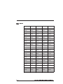
Ramp lookup
table
E - 4
75
4678
7089
8948
10593
721
4775
7144
9035
10716
1054
4876
7257
9125
10716
1324
4982
7314
9216
10842
1562
5092
7373
9216
10842
1776
5207
7493
9309
10971
1973
5297
7554
9404
10971
2158
5389
7617
9501
10971
2333
5486
7680
9501
11104
2498
5585
7745
9600
11104
2656
5689
7877
9600
11239
2810
5760
7945
9701
11239
2954
5870
8014
9804
11378
3103
5946
8084
9804
11378
3245
6063
8156
9910
11378
3376
6144
8229
9910
11520
3504
6227
8303
10017
11520
3628
6312
8378
10127
11520
3762
6400
8455
10127
11666
3889
6490
8533
10240
11666
4007
6583
8613
10240
11815
4114
6678
8613
10355
11815
4228
6727
8694
10355
11815
4347
6827
8777
10473
11969
4452
6929
8862
10473
11969
4562
6982
8948
10593
11969
5240/5220 Programming Reference Manual - Rev C
Appendix F Daisy-Chain Input
Commands
This appendix contains a few guidelines for multi-axis operation
using 5240 units.
As with the single-axis mode, the 5240 echoes all characters
received.
The first character of a command MUST be the “name” character
assigned to the appropriate axis. The command line terminator
MUST be a line feed character (LF = ^J).
name
command (^J)
The line feed “clears” the command buffer for all units. The
controller tests the character immediately following the line feed.
If the character matches the assigned “name”, the 5240 will
interpret the remaining characters (up to 11 characters) as an
input command. If the controller does not detect a proper name
and command, the data is simply echoed to the next controller in
the chain.
The designated controller re-issues the line feed after processing
the command. If the command is of the type that results in a data
output (i.e. Q1), the data (result) will be inserted before the line
feed. The line feed does not indicate that a move or other time
consuming command is completed, but only that it is initiated.
The ESCape command does not require the use of, and will not
be qualified by, a “name” prefix. All controllers in the daisy
chain will respond.
Program entry and editing, though possible, are difficult in
multi-axis mode. It is recommended that programs be entered into
each controller separately, using single-axis mode and then the
controllers connected in a daisy chain. If editing must be done
thorough the daisy chain, enter the edit mode with the line:
“name” E ^J
5240/5220 Programming Reference Manual - Rev C
F - 1
Then enter each program line preceded by “name” and terminated
by ^J.
Note: Unlike editing in single-axis mode, line numbers are not
displayed while editing a program in multi-axis configuration
mode. Also, the List command does not display a complete copy
of the program.
Examples
Assuming two controllers are serially connected with name
assignments of “A” and “B”,. the characters in parentheses are
echoed back to the host after passing through all the controllers.
Input from host
Response from controller
A+1000 (line feed)
A +1000 (line feed)
B-500 (line feed)
B -500 (line feed)
A Q (line feed)
A xxx (line feed)
1. xxx is the data required (the motion parameters of axis A).
2. The Q command , in the multi-axis mode, will return and
display the data in the following format:
mm nnn fff vvv ooo (line feed)
A slight delay may be encountered which is determined by
the baud rate.
Note: The labels that identify the data in the single-axis
configuration are omitted in the daisy chain configuration.
F - 2
5240/5220 Programming Reference Manual - Rev C
Result data
The result output is similar in format to the format for single-axis
mode operation. The ASCII numbers are followed by a line feed
character. The spaces act as delimits for multiple number
responses. Below are a few examples of data output:
A Q1 (LF)
B Q1 (CR, LF)
AQ1
ppp (LF)
BQ1
(CR) ppp (LF)
“ppp” represents the position counter value requested by Q1.
(CR) represents the carriage return character (^M).
(LF) represents the line feed character (^J).
5240/5220 Programming Reference Manual - Rev C
F - 3
Appendix G Command Summary
Command Description
Modes
Refer to Note
A1
Clear and reset controller
Immediate
1
Cn
Current enable
Immediate, program
1
E aa
Edit from address
Immediate
1
F nn
Start/stop speed
Immediate, program
1
G aa b
Go from address, mode
Immediate
1
H nn b
Seek home
Immediate
1
J aa n
Jump to address n+1 times
Program
K
Read input port
Immediate, program
L aa
List from address
Immediate
Mn
Accel/Decel slope
Immediate, program
Op
Distance event
Immediate, program
P
Parameter store
Immediate
Qn
Query
Immediate
R nn
Ramp to velocity
Immediate, program
S
Stop
Immediate, program
U aa k
Loop on input port
Program
V nn
Velocity
Immediate, program
W nn
Wait
Program
Y nn
Set output port
Immediate, program
Zp
Set position counter
Immediate, program
.
Hold and wait
Immediate, program
+nn
Positive incremental move
Immediate, program
5240/5220 Programming Reference Manual - Rev C
2
1
1
G - 1
Command Description
Modes
Refer to Note
-nn
Negative incremental move
Immediate, program
1
@p
Absolute move
Immediate, program
1
^ 11 hh
Jog velocity
Immediate
1
\n
Divide
Immediate, program
1
ESCape
Abort
Immediate
3
1 Command should not be executed with motion in progress.
2 Slope can be changed during ramp to velocity moves.
3 May be executed at any time.
G - 2
5240/5220 Programming Reference Manual - Rev C
5240 Programming
Reference Index
A
A, A1, 3-2
Abort, 3-41
Abort Commands, 1-6
Absolute Move, 3-38
Acceleration/Deceleration Slope, 3-17
All Clear/Restore, 3-2
ASCII Codes, A-1
Edit From Address, 3-5
EEPROM, C-1
ESC, 3-41
ESCape, 1-7
F
F nn, 3-6
G
B
G aa b, 3-8
Go From Address, Trace, 3-8
Baud rate, 1-1
C
C n, 3-3
Command summary, G-1
Current Input, 3-3
D
Daisy Chain Input Commands, F-1
diagram, 1-11
Divide, 3-40, E-2
Distance Event, 3-19
E
H
High speed considerations, D-1
Hold and Wait, 3-34
Home, 3-10
Hs d, 3-10
I
Incremental move, positive, 3-36
Incremental move, negative, 3-37
Immediate mode, 1-3
Inputs, jog, 1-8
E aa, 3-5
Edit mode,
5240/5220 Programming Reference Manual - Rev C
Index - 1
J
O
J aa n, 3-12
Jog inputs, 1-4
Jog velocity, set, 3-39
Jump to Address aa, 3-12
O p, 3-19
Operation, modes of, 1-3
P
P, 3-21
Parameter Store, 3-21, C-1
Position counter, set, 3-33
Programming instructions, 3-1
Program execution mode, 1-5
K
K, 3-13
L
L aa, 3-16
List From Address, 3-16
Lookup table, E-1
Loop On Input Port, 3-27
M
Memory, non-volatile, C-1
M n, 3-17
Modes of operation, 1-3
immediate, 1-3
program execution, 1-5
edit, 1-5
Multi-axis start up, 1-10
Q
Q(n), 3-22
Query, 3-22
Quick reference, 2-1
R
Ramp algorithm & lookup table, E-1
Ramp To Velocity, 3-24
Read I/O Status, 3-13
Remote stop, 1-8
R nn, 3-24
RS-232 serial port, 1-1
N
+ nn, 3-36
- nn, 3-37
”name” command, F-1
Non-volatile memory, C-1
Index - 2
5240/5220 Programming Reference Manual - Rev C
S
Z
S, 3-26
Serial port, RS-232, 1-1
Set Jog Velocity, 3-39
Set Output Port, 3-31
Set Postion Counter, 3-33
Start up
single axis, 1-9
multi-axis, 1-10
Stop, 3-26
Z p, 3-33
T
Terminal program example, B-1
U
U aa k, 3-27
V
Velocity, 3-29
V nn, 3-29
W
Wait, 3-30
Warranty, i
W nn, 3-30
Write cycles, C-1
Y
Yn, 3-31
5240/5220 Programming Reference Manual - Rev C
Index - 3