1
AUTOMATION TECHNOLOGY GROUP
MOTION TECHNOLOGY DIVISION
110 Fordham Road
Wilmington, MA 01887
(978) 988-9800
Fax (978) 988-9940
Part# 903-564502-03
List Price $65 U.S.
August, 1997
Rev F
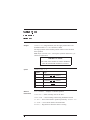
StepperBASIC
Programming Reference Manual
for use with 5645/5445/5345 Microstep Indexer
Rev F
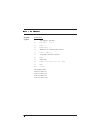
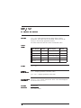
Table
of Contents
.....................................................
1 Conventions
1-1
1.1 Variable Names . . . . . . . . . . . . . . . . . . . . . . . . . . . . . . . 1-1
1.2 Characters . . . . . . . . . . . . . . . . . . . . . . . . . . . . . . . . . . 1-3
1.3 Operators Used in Programming . . . . . . . . . . . . . . . . . . . . . . 1-4
1.4 Constants . . . . . . . . . . . . . . . . . . . . . . . . . . . . . . . . . . 1-6
1.5 Notation Conventions . . . . . . . . . . . . . . . . . . . . . . . . . . . 1-7
1.6 StepperBASICTM Instruction Types . . . . . . . . . . . . . . . . . . . . 1-8
1.7 Interface Requirements . . . . . . . . . . . . . . . . . . . . . . . . . . . 1-10
1.7.1 Setting Up Communications . . . . . . . . . . . . . . . . . . . . . 1-10
1.8 Programming . . . . . . . . . . . . . . . . . . . . . . . . . . . . . . . . 1-14
1.8.1 Programming Modes . . . . . . . . . . . . . . . . . . . . . . . . 1-14
1.8.2 Program Memory and Filing . . . . . . . . . . . . . . . . . . . . 1-15
1.8.3 Writing and Editing Programs in StepperBASIC . . . . . . . . .
1-15
1.8.4 Writing and Editing Programs Using the Screen Editor . . . . . . 1-17
1.8.5 Program Header . . . . . . . . . . . . . . . . . . . . . . . . . . . 1-18
1.9 Error Messages . . . . . . . . . . . . . . . . . . . . . . . . . . . . . . . 1-20
1.9.1 Syntax Errors . . . . . . . . . . . . . . . . . . . . . . . . . . . . 1-20
1.9.2 Runtime Errors . . . . . . . . . . . . . . . . . . . . . . . . . . . . 1-22
1.9.3 System Errors . . . . . . . . . . . . . . . . . . . . . . . . . . . . 1-23
2 Using StepperBASIC Functions
2-1
2.1 Scan Functions . . . . . . . . . . . . . . . . . . . . . . . . . . . . . . . 2-1
2.1.1 Setting the SCAN Trigger Condition . . . . . . . . . . . . . . . . 2-2
2.1.2 Setting the SCAN Output Action . . . . . . . . . . . . . . . . . . 2-2
2.1.3 Enabling and Disabling SCANs . . . . . . . . . . . . . . . . . . . 2-3
2.2 Homing Routines . . . . . . . . . . . . . . . . . . . . . . . . . . . . . . 2-4
2.3 Using the Software Overtravel Limit Function . . . . . . . . . . . . . . 2-4
2.3.1 Setting up the Software Overtravel Function . . . . . . . . . . . . 2-5
2.4 Using the Position Check Function . . . . . . . . . . . . . . . . . . . . . 2-7
StepperBASIC Reference Manual
Rev F
2.5 Using the Position Verification and Correction Function . . . . . . . . 2-10
2.6 Stall Detection Function . . . . . . . . . . . . . . . . . . . . . . . . . 2-13
2.7 Using the WHEN Statement . . . . . . . . . . . . . . . . . . . . . . . 2-17
2.8 Electronic Gearing . . . . . . . . . . . . . . . . . . . . . . . . . . . . 2-19
2.9 Making the Motor Move . . . . . . . . . . . . . . . . . . . . . . . . . 2-23
2.9.1 Descriptions of Motion Statements . . . . . . . . . . . . . . . . 2-25
2.10 Registration Functionality . . . . . . . . . . . . . . . . . . . . . . . . 2-29
3 StepperBASIC Instructions
3-1
4 Quick Reference
4-1
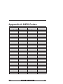
Appendix A ASCII Codes
A-1
Appendix B Input Statements
B-1
Index
Rev F
StepperBASIC Reference Manual
1 Conventions
Introduction
This chapter contains a summary of conventions used with Pacific
Scientific StepperBASIC™. Topics covered are:
• Variable names
• Characters
• Operators used in programming
• Constants
• Notation conventions
• StepperBASIC instruction types
• Getting started
• Programming
• Error messages
1.1 Variable Names
Introduction
Variables are used with BASIC functions and statements for
general programming tasks. There are three basic types of
variables:
• INTEGER
• FLOAT
• FLAG
Variable names are the values acted upon by functions. The
variables are predefined or user-defined.
Note: Variable names are not case sensitive.
Rev F
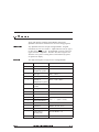
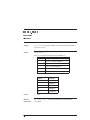
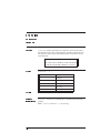
Type of Variable
Characteristic
Integer
4 byte 2’s complement
Float
4 byte IEEE single precision
Flag
single bit flag
StepperBASIC Reference Manual
1 - 1
These three types of variables are organized into two groups:
• Global - meanings and usage defined by Real Time Software
• User - available for user-defined purposes
All three types occur in both groups. Unlike standard BASIC,
Pacific Scientific StepperBASIC variable names are pre-defined.
Note: No variable names other than pre-defined names may be
used. Arrays may not be used.
Examples
Global variables
Type of Variable
Pre-defined Names
Integer
INT1, INT2, INT3, ..., INT32
Floating point
FLT1, FLT2, FLT3, ..., FLT32
Flag
FLG1, FLG2, FLG3, ..., FLG8
Global variables are used to communicate with Real Time
Software. The Real Time Software is that part of the software
which directly controls the motion of the motor. Values of global
variables can be set to control the operation of the motor when
used in conjunction with other commands such as the CALL
command. Other global variables report the current status of
various aspects of motor operation.
Some Global variables are Read-Only. This means that the value
of these variables cannot be changed by the user directly. For
instance, the variable named INPUTS is the current state of
discrete inputs. This value can be printed or used in an
expression, but a new value cannot be assigned to INPUTS by a
Pacific Scientific StepperBASIC program. The only way to
change the value of INPUTS is to actually change the voltage
level at the connector pins used for the discrete inputs.
Note: Global variables are treated the same as user variables
within expressions and programs.
1 - 2
StepperBASIC Reference Manual
Rev F
1.2 Characters
Along with Pacific Scientific StepperBASIC instructions,
alphabetic and numeric characters are used in creating programs.
Alphabetic
Any alphabetic character is legal in StepperBASIC. Program
instructions are not case sensitive. Alpha characters may be typed
in either upper or lower case. StepperBASIC processes all text in
upper case after compilation. The drive does not recognize case
when the text is part of a string, that is text bracketed by quotes
for printout or display.
Numeric
The digits 0 through 9 are legal for use in StepperBASIC.
Character
Rev F
Name
Example
Space
PRINT “Hello”, “ ”, FLT1
=
Equal sign of
assignment symbol
FLT1 = VELOCITY
+
Plus sign
INT1 = INT2 + 3
-
Minus sign
INT1 = RUN.SPEED - 100
∗
Asterisk or
FLT1 = 6.28 * FLT3
multiplication symbol
/
Slash or division
symbol
FLT1 = INDEX.DIST/4096
<>
Not equal
IF VELOCITY < > 0 GOTO 100
<
Less than
IF VELOCITY < 100 GOTO 10
>
Greater than
IF POSITION > 0 GOTO 10
(
Open parenthesis
)
Closed parenthesis
,
Comma
PRINT FLT1, FLT2
;
Semicolon
PRINT “No line feed”;
”
Quote
.
Period, dot or
decimal point
ACCEL.RATE = 10
‘
Single quote
‘This is a comment
INT1 = 3 * (INT2 ∗ INT3)
StepperBASIC Reference Manual
1 - 3
1.3 Operators Used in Programming
Introduction
The operators used by StepperBASIC are arithmetic, relational
and logical, and are evaluated in that order of precedence.
However, operations within parentheses are performed first.
Inside the parentheses the usual order of precedence occurs.
Arithmetic
The arithmetic operators are:
Arithmetic Operator
Description of
Operation
Example
- (one variable)
Negation of value
-3
∗, /
Multiplication/Division
4.21∗3, 10.5/2
+ , - (two variables)
Addition/Subtraction
27 + 8, 19 -2
Note: When multiple arithmetic operators are used in an
expression, they are performed in the order of precedence given in
the table; that is, multiplication is performed before addition, and
so on. Also, integer division is not supported.
Example
Precedence may be altered by the use of parentheses. For example:
INT1 = 2 + 3 ∗ 5
will assign the value 17 (2 + 15) to the variable INT1. The
statement:
INT1 = (2 + 3) ∗ 5
will assign the value 25 (5 ∗ 5) to the variable INT1.
1 - 4
StepperBASIC Reference Manual
Rev F
Relational
Relational operators are used in IF-THEN-ELSE, WHILE-WEND,
and FOR-NEXT statements. The result of a comparison of two
values with these relational operators is recorded by Pacific
Scientific StepperBASIC as either true or false. The relational
operators are:
Relational
Operator
Description of
Operation
Example
Equality
10
IF INT1 = 9 THEN 20
<>
Inequality
50
IF FLT1 < > 9 THEN 15
<
Less than
30
IF INT2 < 151 THEN 100
>
Greater than
10
IF FLT1 > INT2 THEN 20
<=
Less than or
equal to
10
IF FLT1 <= INT2 THEN 20
>=
Greater than or
equal to
10
IF INT3 >= INT5 THEN 20
=
Note: Arithmetic operators are performed before relational
operators in an executing program line. Relational operators are
performed in the order of precedence shown in the table.
Rev F
StepperBASIC Reference Manual
1 - 5
Logical
Logical operators are used in IF-THEN-ELSE, WHILE-WEND,
and FOR-NEXT statements. The logical operators are:
Logical
Operator
Description of Operation Example
NOT
Condition must not be
true
NOT FLG1
AND
Both conditions must be
true
FLG2 AND (INT2 = 5)
OR
Either or both conditions
must be true
FLG1 OR DIR
XOR
Either but not both
conditions must be true
FLG5 XOR FLG6
Note: Logical operators are performed in the order of
precedence given in the table. Arithmetic operators are evaluated
before relational operators.
1.4 Constants
Introduction
Two types of constants may be used with Pacific Scientific
StepperBASIC:
• String constants
• Numeric constants
String
These constants are used with PRINT and INPUT statements. A
string constant is a sequence of alphanumeric characters enclosed
within quotation marks.
Example
“Hello There”
“3.14159”
1 - 6
StepperBASIC Reference Manual
Rev F
These constants are used in numeric expressions, in assignment
statements and in print statements. There are two types of
numeric constants:
Numeric
• integer
• float
Integer
Numbers with no values to the right of the decimal point.
Float
Numbers with values to the right of the decimal point.
1.5 Notation Conventions
The following notation conventions are used in this manual when
explaining StepperBASIC language use.
Notation
Named
Indicates
<return>
“return” surrounded by
angle brackets
the user should press the carriage return
key on the keyboard
[]
square brackets
the entry within the brackets is optional
...
three dots
the entry may be repeated multiple times
capital letters (upper
case)
entries which must be entered exactly as
shown
lower case letters
user-supplied information
Caps/lc
bold typeface capital
and lower case letters
information sent to the terminal screen
/
slash (preceding a
computer command)
a global command or an address
command within a global command
:
colon
separation between multiple commands
entered on the same line
^C
control C
stops operation of program
/^C
slash, control C
a global control C (used to stop all
programs in all controllers)
CAPS
lc
Rev F
StepperBASIC Reference Manual
1 - 7
1.6 StepperBASIC
Instruction Types
Introduction
Pacific Scientific StepperBASIC consists of programming
statements or functions, and arithmetic operations permitted in the
BASIC programming language. A complete list of these
instructions is given in Section 4, “Quick Reference,” of this
manual.
Statements
Statements are of two types, BASIC and StepperBASIC:
• BASIC statements control the flow of instructions within a
program. They direct the execution of functions, for example
comparing function results and going to specific points in the
program based on the comparison, prompting for input,
printing results of functions, and so on. An example of a
BASIC statement is:
GOTO 100
• Pacific Scientific StepperBASIC statements control the motion
of the motor in real time. Motion statements command the
motor to move at constant velocity, to move at a specified
position, etc. An example of a Pacific Scientific
StepperBASIC statement is:
GO.ABS
Commands
Commands normally operate on the program currently residing in
the controller’s memory and are not normally used within a
program. In general, if a command is used in a program the
command will operate properly but the program will be stopped.
For example, if the LIST command appears in a program, the
program will stop operating and list the program. An example of
a command is:
DELETE 120 - 300
1 - 8
StepperBASIC Reference Manual
Rev F
Functions
BASIC functions perform a computation and return a value that
can be used in arithmetic expressions. For example, BASIC
functions convert decimal numbers to integers and convert an
ASCII code to its equivalent screen display character. An
example of a function is:
INT1 = INKEY( )
Pre-defined
variable types
Variables are the values acted upon by functions, or as the result
of arithmetic operations. Variables can be further categorized as
Read/Write (R/W) or Read Only (R/O). Pre-defined variables are
reserved for use with specific Pacific Scientific functions. These
pre-defined variables are either:
• Floating points — numbers with values to the right of the
decimal place. Used with functions that require decimal
numbers, for example the VELOCITY variable contains the
motor speed in revolutions-per-minute.
or
• Integers — integers used with functions that require integers,
for example the number of steps to move the motor. Some
pre-defined variables are read-only, that is they cannot be
altered from the keyboard or by the program. The INPUTS
variable, for instance, is dependent solely on the state of the
programmable inputs at the connector interface and cannot be
altered from the keyboard.
Parameters
Rev F
The 5xx5 Indexer/Drive contain a large number of pre-defined
parameters which specify constraints on motion control and mode
control functions. Parameters are functionally analogous to
variables except once set, they typically remain constant.
StepperBASIC Reference Manual
1 - 9
1.7 Interface Requirements
Terminal types:
You can select two types of interface terminal for controlling the
unit.
Display-only
A display-only “dumb” terminal allows you to type programs and
commands, but will not save programs externally (the program can
be saved in the drive memory).
Note: The T-10C terminal, available from Pacific Scientific, is a
display-only terminal that allows you to enter values and run
downloaded programs.
Computer
A computer terminal allows you to save and work on programs
externally from the controller. In addition, you can use utilities
such as the PacCom Toolkit for editing programs, downloading
programs, and terminal emulation. An example of this type of
terminal is an IBM AT PC.
Terminal
The requirements for the terminal are:
requirements
• RS-232, RS-485, or RS-422 serial communication on board
• 9600 baud transmission rate
1.7.1 Setting Up Communications
Introduction
PacCom
installation
This section covers downloading programs and terminal emulation
using the communications utilities in the PacCom Toolkit.
1. With power disconnected from the unit, verify that the power
and earth ground connections to J1 are correctly installed.
procedure
2. Disconnect the 9-pin connector from J7 to ensure that the
enable input is disconnected.
3. Set up the PC for terminal emulation:
a. Turn On the computer.
b. Load MS-DOS boot up.
1 - 10
StepperBASIC Reference Manual
Rev F
Note: User keyboard entries are indicated in boldface, and
individual key presses, such as <enter>, are in brackets. Prompts
and selections displayed in the StepperBASIC program are
enclosed in quotes.
c. Insert the PacComTM diskette in the A drive, then type
A:<enter> to select drive A.
4. Load PacCom, version 3.1 or higher. For further information,
refer to the PacCom Software Toolkit Instruction Manual.
a. Type paccom <enter>. The Main Menu is displayed.
b. Press <enter> at “Select Hardware.”
c. Use the arrows to move to “5645.”
Note: This selection is also appropriate for the 5345/5445.
d. Press <enter>.
e. Use arrows to move to “Terminal Emulator”, then press
<enter>.
5. Power up the unit per the RS-232 or RS-422/RS-485 procedure.
Power up
procedure -
Perform the following procedure for single units controlled from
the terminal under RS-232.
RS-232
1. Apply power to the controller.
2. Verify that the POWER status indicator on the drive front
panel is On.
3. Verify that the PC display shows the following (versions
higher than 2.3 are acceptable):
Pacific Scientific
Charlestown, MA
StepperBASIC Version X.X
Copyright © 1988. 1991
OK
Program Loaded Properly
Variables Loaded into RAM
Rev F
StepperBASIC Reference Manual
1 - 11
Pack Function Executing ...
Pack Function Done.
where (X.X) is the Version Number
6. Verify operation by typing the following:
RUN.SPEED = 10 <enter>
DIR = 0 <enter>
GO.VEL <enter>
The motor rotates slowly (10 RPM) in the clockwise direction.
7. Stop motor motion by pressing the <Ctrl> and <c> keys.
Continue testing and programming as appropriate for your
application.
8. Press the <Ctrl><e> keys to return to the PacCom Main
Menu for access to other PacCom tools.
Upon successful completion of these procedures, the unit is
ready to be programmed.
Power up
procedure RS-422/RS-485
Perform the following procedure for multiple unit control under
RS-422/RS-485. Follow the steps outlined here to log onto and
test each indexer/drive individually.
1. Apply power to all indexer/drives.
2. Verify that the POWER status indicator on each drive front
panel is On. No cursor or message is displayed on the PC
screen when operating under RS-422/RS-485.
3. Type /x <enter> with the address for the first unit for log on
in the x position.
For example, to log on to a drive with address 1, type / 1
<enter>.
Note: Unique addresses must be set for each unit on the bus.
If incorrect or duplicate addresses are set, erratic
performance will occur. Refer to Section 2.6.2, ”Setting Up
Serial Addresses Using Switch S2”, in the Installation Manual
to set addresses.
1 - 12
StepperBASIC Reference Manual
Rev F
4. The OK prompt is displayed. If you do not see this prompt,
check:
- that you set a unique address
- that you logged on to a valid address
- that the serial cable is properly installed
- the PacCom steps used in setting up the PC
Caution
Do not continue with this procedure until proper serial link
communication has been established.
5. Make sure that the Enable input J7-5 is open and plug the
9-pin connector cable into J7.
6. Enable the drive by connecting Enable J7-5 to ground. Be
ready to disconnect the Enable from ground quickly if
there is unwanted motion or excessive noise from the
motor.
7. Verify operation by typing the following:
RUN.SPEED = 10 <enter>
DIR = 0 <enter>
GO.VEL <enter>
The motor rotates slowly (10 RPM) in the clockwise direction.
8. Stop motor motion by pressing <Ctrl> <c> .
9. Repeat steps 3 to 8 for the other indexer/drives in your
installation.
10. Press <Ctrl> <e> to return to the PacCom Main Menu.
Upon successful completion of these procedures, the
indexer/drive is ready to be programmed.
Rev F
StepperBASIC Reference Manual
1 - 13
1.8 Programming
Introduction
The Pacific Scientific 5xx5 Indexer/Drives control motor velocity
and position. The user interacts with the controller via a computer
or a standard “dumb” terminal. The computer or terminal is
connected to the controller by one of two serial communications
ports:
• RS-232
• RS-485
Using the computer or terminal, they user may “talk” to the
controller by:
• entering BASIC commands via a programming language
(StepperBASIC) similar to standard “BASIC” computer
programming language.
• executing a StepperBASIC program stored in the memory of
the controller by typing RUN <return>.
Note: The controller can hold only one program and has no file
system.
1.8.1 Programming Modes
Mode types
StepperBASIC operates in one of two possible modes, Immediate
or Program.
Immediate
In the immediate mode, statements and commands are executed
when you press <enter> at the end of a line. Results are displayed
immediately, but the instructions cannot be recalled or stored after
they have been used. Use this mode when storing a program is not
needed; for instance, during installation you would type GO.VEL
<enter> to check the motor for excessive vibration. The motor
runs at default velocity until you type STOP <enter>.
Program
The program mode is the program writing and running mode of
the indexer/drive. This mode requires StepperBASIC instructions
preceded by line numbers. To run the program you must enter the
RUN command. Programs created are savable and can be recalled
for repeated use.
1 - 14
StepperBASIC Reference Manual
Rev F
1.8.2 Program Memory and Filing
Introduction
The drive has two types of memory, RAM and non-volatile
battery-backed RAM. The unit operates out of RAM; non-volatile
battery-backed RAM is used for storage (SAVE and SAVEVAR) or
program retrieval (LOAD and LOADVAR):
RAM memory
The drive uses RAM memory for programming and running in the
direct mode. This memory is volatile, that is, it is only available
when the unit has power, and it is lost if power is removed from
the system.
12K (12000 bytes) of memory is available for programming.
Non-volatile
battery-backe d
RAM
The drive uses non-volatile battery-backed RAM memory for
program storage. This memory is non-volatile, meaning that it is
retained if power is removed from the drive.
12K (12000 bytes) of memory is available for storage.
Note: As an alternative, you may choose to upload to PacCom for
storage (if using a computer for terminal emulation).
1.8.3 Writing and Editing Programs in StepperBASIC
Line format
StepperBASIC programs are comprised of lines of instructions,
each starting with a line number and ending when <enter> is
pressed. Line numbers are usually in increments of 10 (10, 20, 30,
and so on), to allow you to insert lines that may have been
overlooked without renumbering all subsequent lines:
Example
20
RUN.SPEED = 200 <enter>
30
ACCEL.RATE = 1000 <enter>
40
PRINT INT1 <enter>
50
IF INT1 = 6 THEN 90 <enter>
.
Rules
Start each line with a number followed by a space.
Use numbers from 1 to 65500
Do not type more than 132 characters on a line.
Rev F
StepperBASIC Reference Manual
1 - 15
Multiple
statements
Multiple instructions may be put on a single line. For ease in
reading, you may separate each instruction by a colon (:), although
this is not required. The program will run faster and take less
memory with no colons. All instructions on the line will be
executed with the same line number.
An example of program line syntax is as follows:
line number statement [ [:statement] ...] <return>
Program lines may not be preceded by the global command prefix
“/”. Thus, there can be no global edits.
If the following line is typed:
/2 INT1=1 : PRINT INT1
a new line 2 will not be added to the program of each controller.
Rather, the following will occur:
• Unit 2 will be logged on and all others will be logged off
• The local variable “INT1” of the controller with address 2 will
be assigned the value of 1
• The value of the variable “INT1” will be printed immediately
Typing in
PacCom
Type your program as if you are typing on a word processor, then
download the program to the drive using the download utility
provided by PacCom.
After a change is made to the program while in PacCom editor,
the program must be saved each time.
Note: While in the PacCom editor mode, there will be no syntax
checking. Syntax checking is only done when downloading the
program to the drive.
1 - 16
StepperBASIC Reference Manual
Rev F
1.8.4 Writing and Editing Programs Using the Screen Editor
Line format
StepperBASIC programs are comprised of lines of instructions,
each starting with a line number and ending when <enter> is
pressed. Line numbers are usually in increments of 10 (10, 20, 30,
and so on), to allow you to insert lines that may have been
overlooked without renumbering all subsequent lines:
Example
20
RUN.SPEED = 200 <enter>
30
ACCEL.RATE = 1000 <enter>
40
PRINT INT1 <enter>
50
IF INT1 = 6 THEN 90 <enter>
Rules
Start each line with a number followed by a space. Or use the
AUTO command to automatically display the next line number
each time you press <enter> when typing in the lines of your
program.
Use numbers from 1 to 65500
Do not type more than 132 characters on a line.
Editing
Once a program has been entered, it may be edited in one of the
following ways:
• a new line may be added to the program
• an existing line may be modified
• an existing line may be deleted
New lines
The line number must be legal and at least one non-blank
character must follow the line number in the line.
Existing line
If a line number that already exists in the program is typed, the
existing line is replaced with the text of the newly entered line
when <return> is entered.
(modifying)
Rev F
StepperBASIC Reference Manual
1 - 17
Existing line
(deleting)
If you type the line number of the line to be deleted with no
characters following the number, that line will be deleted when
<return> is pressed.
To delete an entire program, type:
NEW <return>.
Note: NEW will clear memory prior to entering a new program.
1.8.5 Program Header
To insure that variables previously programmed do not affect
current program, initialize all variables at the start of each
program. This shuts off any forgotten variables that may affect the
current program.
For example, if the Stall Jump Go To Line variable was not set to
zero in memory as follows:
STALL.JUMP = 1000
The variables would still try to jump to a line 1000 upon a stall. If
the current program does not have a line 1000, the program stops
execution upon a stall and displays an error message.
Procedure
1. Type the following immediate mode “header” before the
program:
STEPSIZE = 1
MIN.SPEED = 100
GEARING = 0
ENABLE = 1
RMT.START = 2
PWR.ON.ENABLE = 1
PWR.ON.OUTPUTS = 255
PREDEF.INP = 0 : PREDEF.OUT = 0
POS.CHK1.OUT = 0 : POS.CHK2.OUT = 0 :
POS.CHK3.OUT = 0
OUTPUTS = 255
CW.OT.ON = 0 : CCW.OT.ON = 0
CLR.SCAN1 : CLR.SCAN2
1 - 18
StepperBASIC Reference Manual
Rev F
HOME.ACTIVE = 1
HMPOS.OFFSET = 0
ACCEL.RATE = 1000
MAX.DECEL = 10000
STALL.STOP = 0
STALL.JUMP = 0
POS.VERIFY.JUMP = 0
2. Type in your program, programming variables as needed.
3. When through with the program, type the SAVEVAR command
to save the correct variables and type the SAVE command to
save the final version of your program to memory in case
power is cycled.
Other variables
Other variables need not be included in this header because they
are covered as follows:
CCW.OT, CCW.OT.JUMP, CW.OT, CW.OT.JUMP —
Covered by CW(CCW).OT.ON
DIR, RUN.SPEED — Must be set up as needed before GO.VEL
or SEEK.HOME
ENCODER, RATIO — Covered by GEARING = 0
INDEX.DIST — Must be set up as needed before GO.INCR
JOG.SPEED — Covered by PREDEF.INP = 0
POS.CHKn — Covered by POS.CHKx.OUT = 0
SKn.JUMP, SKn.OUTPUT, SKn.STOP,
SKn.TRIGGER— Covered by CLEAR.SKn
TARGET.POS — Must be set up as needed before GO.ABS
WAIT.TIME — Must be set up as needed before PAUSE
Rev F
StepperBASIC Reference Manual
1 - 19
1.9 Error Messages
There are three types of errors:
Introduction
• syntax
• runtime
• system
Errors are displayed on the terminal screen indicating the type of
error and the error code. All possible errors are listed in the tables
below.
1.9.1 Syntax Errors
A syntax error is an error in the syntax of an entered command.
Syntax errors may appear on the screen when a program is being
entered or when a program is running.
Introduction
Error
Code #
1 - 20
Error
Explanation
1
Command terminator
Not used.
2
Command missing
Program line does not begin with
a valid BASIC statement or
command.
3
Number missing
BASIC was expecting a number.
4
Invalid list
Not used.
5
Statement not entered
BASIC was expecting a
statement.
6
Assignment not entered
BASIC was expecting an equal
(=) sign.
7
THEN not entered
The “THEN” of an
IF-THEN-ELSE statement was
omitted.
StepperBASIC Reference Manual
Rev F
Error
Code #
Rev F
Error
Explanation
8
TO not entered
The “TO” of a FOR-NEXT
statement was omitted.
9
Variable not entered
A variable was omitted.
10
Close parenthesis not
entered
A closed parenthesis “)” was
omitted.
11
Open parenthesis not
entered
An open parenthesis “(” was
omitted.
12
Invalid factor
BASIC was expecting a
constant, variable, function, “(”
or NOT.
13
Unknown identifier
Not used.
14
Quote not entered
A quote (”) was omitted.
15
Digit not entered
A number contains a character
which is not a digit.
16
Comma or semicolon
not entered
A comma (,) or semicolon (;)
was omitted.
20
Error in WHEN
statement
Syntax of WHEN statement is
incorrect.
StepperBASIC Reference Manual
1 - 21
1.9.2 Runtime Errors
A runtime error is an error that occurs during program execution.
Coded runtime errors and their causes are:
Introduction
Error
code #
1 - 22
Error
Explanation
1
Stack overflow
Too many operations caused the
size of the stack to overflow the
amount of available memory.
2
Divide by 0
You may not divide by zero.
3
Exceeding FOR-NEXT Too many FOR-NEXT loops are
nested.
4
No matching NEXT
A “FOR” statement has no
matching “NEXT” statement.
5
No matching FOR
A “NEXT” statement has no
matching “FOR” statement.
6
Exceeded WHILE nest
Too many WHILE-WEND loops
are nested.
7
No matching WEND
A “WHILE” statement has no
matching “WEND” statement.
8
No matching WHILE
A “WEND” statement has no
matching “WHILE”.
9
No line to go to
A “GOTO” or “GOSUB” cannot
find the line number to which to
go.
10
Exceeded GOSUB nest
Too many GOSUB-RETURNs
are nested.
11
No matching GOSUB
A “RETURN” is encountered
before a GOSUB.
12
S-Curve Error
This is a profile generator error.
13
Registration overrun
Registration re-triggers before
registration GOSUB completes
execution.
StepperBASIC Reference Manual
Rev F
1.9.3 System Errors
A system error is a serious error which can only be fixed by
changes to the software system. Coded system errors are as
follows:
Introduction
Error
Code #
Rev F
Error
Explanation
1
Line without a line
number
There is no line number
associated with the line. Thus,
the integrity of the program is
lost.
2
Invalid token
A token cannot be converted
back into a known symbol while
attempting to list a program.
3
No more program
memory
The program cannot be fit into
the available memory.
4
Renumber table
overflow
Occurs during a “RENUM”
command. The temporary
number table size is exceeded.
5
GOTO table overflow
Occurs when a program is
running and the GOTO table
overflows. The GOTO table is
used to store line number
positions so they only have to be
looked up once.
StepperBASIC Reference Manual
1 - 23
2 Using StepperBASIC Functions
In this chapter
This chapter provides an in-depth description of how to perform
certain actions using StepperBASIC. These include the following:
• Scan functions
• Homing routines
• Overtravel limits
• POSITION check function
• Position verification and correction function
• Stall detection function
• Using the WHEN statement
• Electronic gearing
• Making the motor move
• Registration functionality
2.1 Scan Functions
Introduction
The purpose of the SCAN functions is to allow you to specify an
action to be taken when a given discrete input condition is
satisfied. The specified input condition is tested every millisecond
and the specified action is performed immediately as soon as the
condition is satisfied.
Similar functionality can be performed by an IF...THEN
statement in your Pacific Scientific StepperBASIC program.
However, using a SCAN function has two key advantages:
1. The SCAN response will be much faster than the
IF...THEN response because the SCAN condition is tested
every millisecond and the SCAN action is performed as soon
as the condition is satisfied.
2. When the SCAN function is used, there is no need to have a
program loop that regularly tests the specified condition.
Once the SCAN function is set up and turned on, the SCAN
condition will be automatically tested every millisecond until
the SCAN function is turned OFF.
Rev F
StepperBASIC Reference Manual
2 - 1
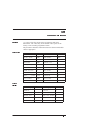
2.1.1 Setting the SCAN Trigger Condition
The SCAN input condition, which is also referred to as the SCAN
Trigger Condition, is specified using the variable SKn.TRIGGER.
The first digit of SKn.TRIGGER specifies which one of the
sixteen discrete inputs the SCAN is checking. The second digit of
SKn.TRIGGER specifies whether the SCAN condition is satisfied
when the input is equal to zero or whether the SCAN condition is
satisfied when the input is equal to 1.
For example:
SKn.TRIGGER = 51
sets the SCAN condition as input 5 (INP5) being equal to 1.
2.1.2 Setting the SCAN Output Action
There are three actions which can be performed when the SCAN
Trigger Condition is satisfied. Any combination of these actions
can be specified. The four available output actions are:
1. Turn a specified output ON or OFF. This action is specified
using the variable SKn.OUTPUT.
2. Stop the motor. This action is specified by setting the variable
SKn.STOP to 1. If SKn.STOP is set to zero, the motor will
not be stopped when the SCAN Trigger Condition is satisfied.
3. Jump to a specified line of the StepperBASIC program. This
action is specified using the variable SKn.JUMP. If
SKn.JUMP is set to zero, then the StepperBASIC program
will not be affected when the SCAN Trigger Condition is
satisfied. If SKn.JUMP is set to a non-zero value the
program will commence execution at the instruction specified
by the SKn.JUMP program line.
Note: Use of the SCAN jump (SKn.JUMP) functions may
absolutely require the execution of the RESET.STACK statement
to ensure internal program control is restored if the SCAN input
has been triggered during execution of a subroutine or looping
construct.
2 - 2
StepperBASIC Reference Manual
Rev F
2.1.3 Enabling and Disabling SCANs
SCAN functions are enabled or disabled as follows:
• The SCAN function is enabled by executing SET.SCANn.
• The SCAN function is disabled by executing CLR.SCANn.
Example
As an example, suppose you have an End of Travel Limit Switch.
If this switch is activated, then all motion must stop, an output
must be turned on and a message must be displayed on the screen
of the terminal. The following segment will perform this function:
10
20
30
40
50
.
.
.
2000
2010
2020
SK1.TRIGGER = 10
SK1.STOP = 1
SK1.JUMP = 2000
SK1.OUTPUT = 11
SET.SCAN1
PRINT “End of Travel Limit Switch activated”
IF INP1 = 0 THEN 2010
GOTO 100
Line 10 specifies the SCAN trigger condition as input 1 going to a
low voltage.
Line 20 specifies that the motor will stop when the SCAN
condition is satisfied.
Line 40 specifies that Output 1 will be turned Off when the Scan
condition is satisfied.
Line 50 enables the SCAN function.
Line 2000 prints a message on the terminal screen. This message
will be displayed when the SCAN condition is satisfied.
Line 2010 waits until 1 goes to a high voltage before proceeding
to line 2020.
Line 2020 jumps to line 100 which should be a program restart
routine in this example.
Rev F
StepperBASIC Reference Manual
2 - 3
2.2 Homing Routines
Pacific Scientific StepperBASIC is an absolute positioning system.
It maintains a position counter (POS.COMMAND) and is capable of
moving the motor shaft to any absolute position. The position
counter has a range of approximately -32,000 revolutions to
+32,000 revolutions of the motor shaft.
Electrical home
The position at which the position counter (POS.COMMAND)
equals zero is called the electrical home position. The electrical
home position can be established by executing the SEEK.HOME
function. After the SEEK.HOME function is performed, the motor
will be at the electrical home position and POS.COMMAND will be
zero. All absolute positions will then be referenced to this
electrical home position.
Note: Refer to Section 2.9, “Making the Motor Move”, for more
information on SEEK.HOME.
At any point, you may move to the electrical home position by
executing the GO.HOME function. This function is exactly
equivalent to setting TARGET.POS to zero and executing the
GO.ABS (go to absolute position) function.
2.3 Using the Software Overtravel Limit Function
Introduction
The software overtravel limit function is used to prevent the motor
from traveling outside predefined limits. Two independent
overtravel limits may be specified, one for limiting travel in the
clockwise direction and the other for limiting travel in the
counterclockwise direction.
Note: Either one or both or these limits may be enabled at any
time.
2 - 4
StepperBASIC Reference Manual
Rev F
Overtravel limit
exceeded
If either the clockwise and/or the counterclockwise overtravel limit
function is enabled the internal software constantly checks the
motor position and compares it to the overtravel limits. If the
motor position exceeds the overtravel limit (and that overtravel
limit is enabled) then the controller will decelerate the motor to a
stop and will prevent further motion in the direction for which the
limit was exceeded.
In addition, a program line number may be specified for each of
the two limits. If a program line number is specified then the
program will jump to that line when the corresponding overtravel
limit is exceeded. This allows you to write a recovery routine for
an overtravel error.
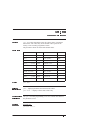
2.3.1 Setting up the Software Overtravel Function
To use the overtravel limit function set up the following variables:
VARIABLE
DESCRIPTION
CW.OT
Specifies the maximum clockwise position
CW.OT.ON
Specifies whether or not the clockwise
overtravel checking is enabled
CW.OT.JUMP
Specifies the line number to be jumped to
when the clockwise overtravel limit is exceeded
CCW.OT
Specifies the maximum counterclockwise
position
CCW.OT.ON
Specifies whether or not the counterclockwise
overtravel checking is enabled
CCW.OT.JUMP Specifies the line number to be jumped to
when the counterclockwise overtravel limit is
exceeded
Note: If you do not want the program to jump to a new line
number when the overtravel limit is exceeded, then you must set
the jump destination (CW.OT.JUMP or CCW.OT.JUMP) equal to
zero.
Rev F
StepperBASIC Reference Manual
2 - 5
OT.ERROR
Example
2 - 6
Note: The variable OT.ERROR is set by the internal software to
reflect the status of the overtravel function. OT.ERROR always
has one of the following values:
VALUE
DESCRIPTION
0
No overtravel detected
1
Clockwise overtravel detected
2
Counterclockwise overtravel detected
10
POS.COMMAND = 0
20
30
40
50
60
70
80
90
100
110
120
130
140
.
.
.
200
210
215
220
300
310
315
320
CW.OT = 100000
CW.OT.JUMP = 200
CW.OT.ON = 1
CCW.OT = -100000
CCW.OT.JUMP = 300
CCW.OT.ON = 1
DIR = 0
STEPSIZE = 25
MIN.SPEED = 25
ACCEL.RATE = 5000
RUN.SPEED = 100
GO.VEL
GOTO 110
PRINT “Clockwise Overtravel”
DIR = 1
GO.VEL
GOTO 110
PRINT “Counterclockwise Overtravel”
DIR = 0
GO.VEL
GOTO 110
StepperBASIC Reference Manual
Rev F
Explanation
This example sets up a clockwise overtravel limit of 100000
microsteps and a counterclockwise overtravel limit of -100000
microsteps. The example sets the clockwise jump line number to
200 and sets the counterclockwise jump line number to 300. The
two limit checks are turned on and the motor is commanded to
turn at 100 rpm in the clockwise direction.
When the clockwise overtravel limit is exceeded the motor will
decelerate to a stop and the program will transfer control to line
200. At line 200 a message is printed, the motor direction is
reversed and control is passed back to line 110.
When the counterclockwise overtravel limit is exceeded the motor
will decelerate to a stop and the program will transfer control to
line 300. At line 300 a message is printed, the motor direction is
reversed and control is passed back to line 110.
This process will continue until the program is aborted.
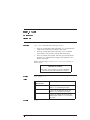
2.4 Using the Position Check Function
Introduction
The position check function is used to allow the internal software
to automatically turn On (set to 0) or turn Off (set to 1) an output
discrete (OUT1, OUT2 and/or OUT3) based upon the motor’s
position.
Note: Up to three position check functions may be defined at any
time.
When a position check function has been defined, the internal
software checks the motor position every 2.048 msec and either
turns On or turns Off the appropriate discrete output depending
upon whether the motor position is greater than or less than the
specified check position.
Rev F
StepperBASIC Reference Manual
2 - 7
Three
independen t
position checks
To set up the position check function, two variables must be
specified for each of the three position checks which may be
defined.
VARIABLE
DESCRIPTION
POS.CHKn
Specifies the position check value
POS.CHKn.OUT Specifies whether or not position check is
enabled and if enabled, whether Output n
(OUTn) is to be turned On or Off.
POS.CHKn.OUT may be set to one of three
values:
0
Position check n is disabled
10
OUTn = 0 if the motor position is
greater than POS.CHKn
OUTn = 1 if the motor position is
less than POS.CHKn
11
OUTn = 1 if the motor position is
greater than POS.CHKn
OUTn = 0 if the motor position is
less than POS.CHKn
The value of n can be 1, 2 or 3.
Note: Once a position check has been enabled by setting
POS.CHKn.OUT (where n’s value is 1, 2, or 3) equal to 10 or 11
the corresponding output cannot be changed by the program (e.g.
OUTn = 1) until that position check has been disabled.
2 - 8
StepperBASIC Reference Manual
Rev F
Example
10
POS.COMMAND = 0
20
30
40
50
60
70
80
90
100
110
120
POS.CHK1 = -5000
POS.CHK2 = 0
POS.CHK3 = 5000
POS.CHK1.OUT = 10
POS.CHK2.OUT = 11
POS.CHK3.OUT = 10
TARGET.POS = -10000
GO.ABS
TARGET.POS = 10000
GO.ABS
GOTO 80
Line 10 defines the current position as home.
Lines 20 through 40 set position check 1 to -5000, position check
2 to 0 and position check 3 to 5000.
Lines 50 through 70 turn On all position checks and specify the
output states.
Lines 80 through 120 command the motor to move from -10000 to
+10000 continuously.
Rev F
StepperBASIC Reference Manual
2 - 9
2.5 Using the Position Verification and Correction
Function
Introduction
For incremental and absolute moves, Pacific Scientific
StepperBASIC compares incremental distance traveled by the
encoder to the distance commanded on the motor shaft.
Setting up for
Position
Verification
There are five variables associated with the Position Verification.
These are:
VARIABLE
DESCRIPTION
POS.VERIFY.TIME
User defined variable which specifies the
amount of wait time in milliseconds after the
positioning move is finished before it looks at
the encoder position. This will allow for any
ringing to settle.
POS.VERIFY.CORRECTION
A read only variable that gives the difference
between the rotor position and the position
command in number of microsteps, NOT
ENCODER COUNTS. It is to be used as the
correction distance.
POS.VERIFY.ERROR
This is a flag that is tripped when the rotor error
between the rotor position and the commanded
position is greater than that allowed by the
POS.VERIFY.DEADBAND.
POS.VERIFY.DEADBAND
Is the allowable error in microsteps (± this
number) in a system. If the error between the
commanded position and the position measured
by the encoder exceeds this value, the
POS.VERIFY.ERROR flag will be tripped.
POS.VERIFY.JUMP
Causes the program to jump to a new line when
the POS.VERIFY.DEADBAND is exceeded.
This will allow the correction to be made based
upon the commands at the line jumped to.
2 - 10
StepperBASIC Reference Manual
Rev F
Related
Commands
VARIABLE
DESCRIPTION
ENCODER
Should be set to the number of PPR (pulses per revolution) of
your encoder.
STEP.DIR.INPUT
Set up the encoder port for an encoder or step and direction
inputs from another control.
Note: If STEP.DIR.INPUT = 1 for accepting step and
direction inputs, ENCODER needs to be set to Stepsize * 50.
IN.POSITION
Flag controlled by the internal software that indicates when the
motor is in position. This flag is set by the internal software to 1
or 0. It will be set to 1 when the following conditions are true:
* Motor commanded to be stopped (the last move is completed).
* POS.VERIFY.DEADBAND has not been exceeded.
Example
10 STEPSIZE = 25
20 MIN.SPEED = 5
30 RUN.SPEED = 1000
40 ACCEL.RATE = 5000
50 ENCODER = 1250
60 INDEX.DIST = 20000
70 POS.VERIFY.TIME = 200
80 POS.VERIFY.DEADBAND = 10
90 POS.VERIFY.JUMP = 1000
100 POS.COMMAND = 0
110 ENCDR.POS = 0
120 GO.INCR
130 IF MOVING THEN 130
140 GOTO 2000
Rev F
StepperBASIC Reference Manual
2 - 11
1000 PRINT “I AM CORRECTING”
1010 INDEX.DIST = POS.VERIFY.CORRECTION
1020 GO.INCR
1030 IF MOVING THEN 1030
1040 IF POS.VERIFY.ERROR THEN 1010 ELSE 2000
2000 PRINT “FINAL POSITION IS ” POS.COMMAND
2010 PRINT “FINAL ENCODER POSITION IS ”
ENCDR.POS
2020 END
Explanation
Line 10 sets the software stepsize variable (both
software and hardware stepsize should be the same).
Line 20 sets the start/stop speed to 5 rpm.
Line 30 sets the run speed to 1000 rpm.
Line 40 sets the acceleration rate to 5000 rpm/sec.
Line 50 sets the encoder variable to 1250 ppr.
Line 60 sets an incremental move of 20000
microsteps (4 revs).
Line 70 sets a wait time of 200 msec before reading the encoder
position.
Line 80 sets the maximum microstep difference
allowed for measured encoder counts versus
commanded microsteps counts to 10 counts.
Line 90 moves the program execution to line 1000
when the POS.VERIFY.ERROR is tripped.
Line 100 sets the position counter to 0 (zero).
Line 110 sets the encoder counter to 0 (zero).
Line 120 initiates an incremental move.
Line 130 holds the program executions until the move is
completed.
Line 140 causes the program to jump to line 2000.
2 - 12
StepperBASIC Reference Manual
Rev F
Explanation
(contd)
Line 1000 will print “I AM CORRECTING” if the error
had exceeded the POS.VERIFY.DEADBAND limit set in
line 80.
Line 1010 sets an incremental correction move
equal to the POS.VERIFY.CORRECTION variable.
Line 1020 initiates the incremental correction move.
Line 1030 holds the program as long as the move is not completed.
Line 1040 checks if there is a position error after the correction
move has been completed and if there is an error it will correct
again otherwise it will force the execution of the program to go to
line 2000.
Line 2000 will print the final encoder position after the motor
rotation has stopped.
Line 2010 will terminate the program execution.
2.6 Stall Detection Function
Introduction
Rev F
The Stall Detection Command, detects a stall
condition based upon the users allowable difference
between the motor commanded position and the actual
rotor position. The encoder could be in/on the
motor or the load axis.
StepperBASIC Reference Manual
2 - 13
Setting Up For
Stall Detection
There are four variables associated with the Stall Detection
function:
VARIABLE
DESCRIPTION
STALL.DEADBAND
Sets the maximum step difference allowed between the
commanded and measured steps (commanded position
versus rotor or encoder counts).
STALL.STOP
Stops the motor at the rate set by MAX.DECEL when a
stall is detected (the STALL.ERROR FLAG = 1, tripped).
STALL.ERROR
Flag controlled by the internal software that indicates a
stall has occurred (the STALL.DEADBAND variable had
exceeded). It is reset back to zero at the start of the next
move.
STALL.JUMP
A variable that moves the program execution to a new line
when STALL.ERROR is tripped (stall occurs).
Related
instruction s
VARIABLE
DESCRIPTION
MAX.DECEL
A variable that sets the maximum deceleration rate in
rpm/sec at which the motor will decelerate to stop.
The encoder position and the position command are sampled at 8
msec intervals. The value at each sample is compared to the last
sample only. If the difference is larger than the
STALL.DEADBAND value, STALL.ERROR will be set to 1.
Due to the 8 msec sample rate and since the error does not
accumulate, there are limitations in the size of the
STALL.DEADBAND.
2 - 14
StepperBASIC Reference Manual
Rev F
Maximum
The following equation is used to calculate the maximum
deadband allowed as a function of rotor speed.
Maximum STALL.DEADBAND = 8 * RPM * (#step/rev)/60000
Note: If a larger value is used, the indexer will not detect a stall
condition.
Minimum
The minimum value for the stall deadband can be calculated using
the following equation:
Minimum STALL.DEADBAND = 4 * STEPSIZE
In general stepper motors will lose 4 full steps at once when they
stall. The above equation will allow 4 full steps of error before a
stall is being detected.
Example
10 STEPSIZE = 25
20 MIN.SPEED = 5
30 ACCEL.RATE = 1000
40 MAX.DECEL = 1000
50 RUN.SPEED = 800
60 INDEX.DIST = 75000
70 ENCODER = 1250
80 STALL.DEADBAND = 100
90 STALL.JUMP = 1000
100 STALL.STOP = 1
110 POS.COMMAND = 0
120 ENCDR.POS = 0
130 GO.INCR
140 IF MOVING THEN 140
150 GOTO 110
1000 PRINT “ MOTOR STALLED ”CINT (ENCDR.POS) “
STEPS FROM START.”
1010 END
Rev F
StepperBASIC Reference Manual
2 - 15
Explanation
Line 10 sets the software stepsize variable to 25.
Line 20 through 50 sets the move profile parameters.
Line 60 sets an incremental move to 75000 steps (15 revs).
Line 70 sets the encoder to 1250 ppr.
Line 80 sets the allowable error to 100.
Line 90 will force the program to jump to line 1000 and
start executing if a stall is detected (STALL.ERROR = 1).
Line 100 will cause the motor to stop using the DECEL.RATE
of 1000 rpm/sec if a stall is detected (STALL.ERROR = 1).
Line 110 and 120 will reset the position command and the
encoder counters to zero (0).
Line 130 will initiate the incremental move.
Line 140 will hold the program until the motion is
completed.
Line 150 will take the program back to line 110.
Line 1000 will print MOTOR STALLED XXXXXX STEPS
FROM START, if a stall is detected (STALL.ERROR = 1).
2 - 16
StepperBASIC Reference Manual
Rev F
2.7 Using the WHEN Statement
The WHEN statement is used to get extremely fast response to
certain input conditions. When the Pacific Scientific
StepperBASIC program encounters a WHEN statement, it tests the
specified condition every 1.024 msec and as soon as the condition
is satisfied, the specified output action is initiated.
When the StepperBASIC program encounters a WHEN statement,
the program will not proceed to the next line of the program until
the WHEN condition is satisfied. When the WHEN condition is
satisfied and the specified action has been performed, the WHEN
statement is complete. In order to execute this function again you
must execute another WHEN statement.
For example, if you desire the motor to rotate at 1000 RPM until
Input 3 is pulled low (INP3 = 0) at which point the motor is to be
decelerated to 500 RPM, you use the following program:
10
20
30
40
RUN.SPEED = 1000
GO.VEL
RUN.SPEED = 500
WHEN INP3 = 0, GO.VEL
In this example, line 40 causes Input 3 to be checked every 1.024
msec. As soon as Input 3 is seen to be low (INP3 = 0) the
program will execute a GO.VEL (go at velocity) move.
The syntax for using the WHEN statement is:
[line number] WHEN condition, action
Condition
The condition specifies what condition must be satisfied before the
action is performed. The condition may be any one of the
following:
• Checking for an input to be equal to 0 or 1.
• Checking for the position command to be greater than or less
than some value.
• Checking for the position to be greater than or less than some
value.
• Checking for the Encoder position to be greater than or less
than some value.
Rev F
StepperBASIC Reference Manual
2 - 17
Action
The action specifies what operation is to be taken when the
condition is satisfied. The action may be any one of the following:
• Setting an Output equal to 0 or 1.
• Setting RATIO equal to a new value.
• Turning GEARING ON/OFF
• Turning REG.FUNC ON/OFF
• Performing any one of the following functions:
GO.ABS
GO.HOME
GO.INCR
GO.VEL
PAUSE
UPD.MOVE
SEEK.HOME
STOP.MOTION
• Allowing program execution to continue to the next instruction
(with no action performed).
On the 1.024 msec sample that the WHEN condition is satisfied and
the action is performed the values of POS.COMMAND, and
ENCDR.POS are stored in the variables WHENPCMD, and
WHEN.ENCPOS respectively. The values of these variables may
be used for even greater synchronization.
The following list is a sampling of some possible WHEN statements:
50
60
100
320
360
870
900
950
2 - 18
WHEN
WHEN
WHEN
WHEN
WHEN
WHEN
WHEN
WHEN
INP1 = 1, GO.VEL
INP3 = 0, OUT4 = 1
POS.COMMAND < INT6, STOP.MOTION
ENCDR.POS > INT3, GO.INCR
INP6 = 1, RATIO = FLT4
POSITION > 40960, CONTINUE
REG.FLAG, OUT2 = 1
INP5, REG.FUNC = 1
StepperBASIC Reference Manual
Rev F
Example
The following program is an example of using the WHEN
statement. This program executes an incremental move as soon as
INP3 goes low. It then waits for INP3 to go high again. When
INP3 goes high, the program goes back to waiting for INP3 to
go low so that it can perform another incremental move.
The response time from INP3 going low to the motor motion
starting will be approximately 1 msec.
10
20
30
40
INDEX.DIST = 40960
WHEN INP3 = 0, GO.INCR
WHEN INP3 = 1, CONTINUE
GOTO 20
2.8 Electronic Gearing
Introduction
Electronic gearing allows you to control the movement of the
motor shaft from an external source. Gearing usually is done with
encoder inputs. However, it can be performed using Step/Dir
inputs also.
To use electronic gearing, you must provide an external encoder or
differential Step/Dir source. This external source is used as a
master reference for electronic gearing must provide differential,
line driver type outputs in quadrature form. The receiver IC is an
SN75175.
Rev F
StepperBASIC Reference Manual
2 - 19
The encoder inputs must be wired up as follows:
Encoder Signal
Pin Number
CHA (STEP)
J6-2
CHA (STEP)
J6-3
CHB (DIR)
J6-4
CHB (DIR)
J6-5
Encoder +5V
J6-8
Encoder GND
J6-9
Note: An external power supply may be used to power
up the encoder. If this is done then the power supply ground must
be connected to J6-9.
That also applies if a differential Step/Dir source was used as a
“MASTER”, then a GND (common) from this source must be
connected to J6-9.
Encoder position
When an external reference (source) has been connected the
encoder position variable (ENCDR.POS) is updated by the internal
software every 1.024 msec. The value of the
encoder position is contained in the variable ENCDR.POS. This
variable continues to be updated even if electronic gearing is
turned off.
Setting the
electronic gear
ratio
The variable RATIO is used to specify the electronic gear ratio.
VARIABLE
DESCRIPTION
RATIO
Specifies the electronic gear ratio in terms of motor shaft to
encoder (Step @ Dir) shaft movement. The line count
of the master encoder must be specified in order to use the
RATIO variable.
Note: The actual gear ratio will be specified by the most recently
specified value.
2 - 20
StepperBASIC Reference Manual
Rev F
Related
instruction s
VARIABLE
DESCRIPTION
STEPSIZE
Step size must be >= 5 for gearing.
STEP.DIR.INPUT
Set up the encoder port to see an encoder or step @
direction inputs.
ENCODER
Should be set to the number of PPR of the installed
encoder.
Turning electronic
gearing ON and
OFF
• Bi-directional electronic gearing is enabled by setting
GEARING equal to 1.
• Electronic gearing is disabled by setting GEARING equal to 0.
• Electronic gearing, in the clockwise direction only, is enabled
by setting GEARING equal to 2.
• Electronic gearing, in the counterclockwise direction only, is
enabled by setting GEARING equal to 3.
Note: The STOP.MOTION instruction will not stop the motor
motion resulting from gearing. Therefore, turn gearing off
(GEARING = 0) before stopping motion.
• The variable MOVING does not recognize moving caused by
GEARING.
• If directional limits are set, gearing motion in the allowed
direction occurs only when the master encoder returns to the
point where it originally reversed direction.
• Other motion commands could result in motion in the
disabled gearing direction.
• The variable (read only) VELOCITY will return the actual
speed at which the motor is running.
Note: The minimum step size required is 5.
Rev F
StepperBASIC Reference Manual
2 - 21
Example
10 STEPSIZE = 25
20
30
40
50
60
70
STEP.DIR.INPUT = 0
ENCODER = 1250
RATIO = 2
GEARING = 1
WHEN INP1 = 1, CONTINUE
GEARING = 0
Line 10 sets the step size to 25 (both hardware and software
should be the same settings).
Line 20 configure J6 inputs for encoder type signal.
Line 30 the installed encoder provides a 1250 PPR (5000
quadrature counts per rev).
Line 40 sets 2 motor shaft turns per encoder shaft
revolution.
Line 50 Turn gearing ON.
Line 60 Holds the program at this line until input 1
goes high.
Line 70 Turns OFF gearing.
Using the STEP
and DIR Outputs
The controller’s STEP @ DIR out (J7), generates differential
signals as long as there is motion in progress.
These output signals can be used to drive two other controllers.
The two controllers (slaves) will follow the master’s exact profile
(speed and direction).
These output signals are fed back to the same controller (J6) when
registration functionality is required. Refer to Section 2.10,
“Registration Functionality” for additional information.
2 - 22
StepperBASIC Reference Manual
Rev F
2.9 Making the Motor Move
Introduction
There are six different statements which you can use to make the
motor move:
• GO.VEL
• GO.INCR
• GO.ABS
• GO.HOME
• SEEK.HOME
• GEARING
Each of these provides a different type of movement, described as
follows. The instruction GEARING is covered in Section 2.8,
“Electronic Gearing”
Program
execution
These instructions, except for SEEK.HOME, do not wait for
completion before continuing to the next line. For example, after a
GO.INCR is encountered, the program immediately goes to the
next line even though the move is still executing.
(The SEEK.HOME function waits for completion of the move
before the program continues to the next line.)
Rev F
StepperBASIC Reference Manual
2 - 23
Common
variables
Common variables for motion instructions are as follows. Specific
instructions are given in the appropriate instruction section.
1. ENABLE = 1. Also, enable the hardware, pulling the Enable
input low. If not done, motion instructions are ignored.
2. RUN.SPEED will determine the motor speed.
3. ACCEL.RATE (and optionally DECEL.RATE) will determine
the acceleration rate and the deceleration rate.
4. MIN.SPEED sets the initial velocity step
5. STEPSIZE sets the amount of rotation per input step (Both
hardware and software should be the same)
Note: RUN.SPEED, ACCEL.RATE, and MIN.SPEED are not
required for GEARING.
RUN.SPEED and ACCEL.RATE can be changed while a move is
in progress using UPD.MOVE (Update Move).
Stopping the
motor
There are several ways to stop the motor after a motion statement
has been executed.
• Wait for the motion to be completed.
Note: This does not apply to the GO.VEL statement.
• Type <Ctrl><C> .
• Pull the Remote Stop input low
(J5-5 with PREDEF.INP13 = 1 )
• Remove the ENABLE input from the control
Note: This will disable the motor current and torque but may not
cease motion.
• Execute a STOP.MOTION statement.
Note: Either LIMIT(-) (J5-3 with PREDEF.INP11 = 1 ) or
LIMIT (+) (J5-2 with PREDEF.INP10 = 1) inputs pulled low.
2 - 24
StepperBASIC Reference Manual
Rev F
The program stops the motor if:
• A scan triggers and a scan stop is active (SKn.STOP = 1) .
• A software overtravel has occurred.
• A stall occurs causing a STALL.STOP.
Continuou s
motion
CONTINUOUS.MOTION enables motion to proceed continuously
over multiple motion instructions.
2.9.1 Descriptions of Motion Statements
GO.VEL
This statement causes the motor to move at the specified run speed
(RUN.SPEED). The direction of rotation is specified by the DIR
variable as follows:
Value
Functionality
DIR = 0
Motor rotates clockwise
DIR = 1
Motor rotates counterclockwise
After the GO.VEL statement has been executed, the motor will
continue to rotate at the specified RUN.SPEED until one of the
STOP conditions described above occurs or until another GO.VEL
statement is executed.
If another GO.VEL statement is executed, then motor will
accelerate (or decelerate) to the new value of RUN.SPEED. If the
new value of RUN.SPEED is zero, the motor will decelerate to a
stop and the GO.VEL move will be complete.
Note: If you terminate the GO.VEL move by setting RUN.SPEED
equal to zero and executing a GO.VEL statement than you must
set RUN.SPEED equal to a non-zero value before attempting to
execute another motion statement.
Rev F
StepperBASIC Reference Manual
2 - 25
GO.INCR
Direction
2 - 26
This statement causes the motor to rotate a specified amount
(INDEX.DIST). The software uses a trapezoidal velocity profile
to rotate the motor. The acceleration rate is specified by
ACCEL.RATE and the slew speed is specified by RUN.SPEED
and MIN.SPEED sets the initial velocity step.
The direction of rotation is determined by the sign of
INDEX.DIST:
Value
Functionality
INDEX.DIST > 0
Motor rotates clockwise
INDEX.DIST < 0
Motor rotates counterclockwise
StepperBASIC Reference Manual
Rev F
GO.ABS
This statement causes the motor to move to an absolute position.
This absolute position is specified by the variable TARGET.POS.
The absolute position is relative to the HOME position (i.e. the
place where POS.COMMAND = 0).
The direction of motor rotation is determined by the value of
TARGET.POS and the current value of POS.COMMAND.
Value
Functionality
TARGET.POS >
POS.COMMAND
Motor rotates clockwise
TARGET.POS <
POS.COMMAND
Motor rotates
counterclockwise
The GO.HOME statement is exactly equivalent to:
TARGET.POS = 0 : GO.ABS
GO.HOM E
Direction
Rev F
This statement moves the motor to the zero, home position
(electrical home where POS.COMMAND = 0).
Direction of motor rotation is specified by the current value of
POS.COMMAND relative to 0 (zero):
Value
Functionality
POS.COMMAND
> 0
Motion goes in negative direction to 0
(zero)
POS.COMMAND
< 0
Motion goes in positive direction to 0
(zero)
StepperBASIC Reference Manual
2 - 27
SEEK.HOME
This statement causes the motor to move to mechanical home
position, as defined by an external limit switch connected to J5-8.
Upon initiation, the following steps occur:
1. The motor moves as specified by DIR (direction),
RUN.SPEED, ACCEL.RATE.
2. When the switch is found , it changes state (the variable
HOME.ACTIVE should be set to correspond to the desired
state change).
3. The motor decelerates to a stop.
4. Direction reverses and the motor moves slowly (defined by
MIN.SPEED) until the switch changes again.
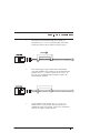
VELOCITY
RUN.SPEED
(RPM)
SLOPE =
ACCEL.RATE (RPM/S)
SWITCH CHANGES
STATE
MIN.SPEED
(RPM)
TIME
MIN.SPEED
(RPM)
5. Motion is stopped. This position is defined as mechanical
home. If no offset is programmed (see following), this
position is also defined as electrical home (where
POS.COMMAND = 0).
If an offset is needed, you can program HMPOS.OFFSET to add
an additional incremental move when the mechanical home
position is reached. This position is electrical home
(POS.COMMAND = 0).
2 - 28
StepperBASIC Reference Manual
Rev F
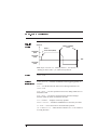
2.10 Registration Functionality
Introduction
In motion control terms, registration provides the ability to execute
a preset move with reference to an external event while the motor
is executing another move. This done by beginning with the
executing of a long move which would, under normal conditions,
cause the index to go beyond the registration mark.
As the move proceeds, the sensor detects the presence of the
registration mark. It then aborts the current move and, without
stopping, begins the Registration Move to the precise position.
REGISTRATION
MARK APPLIED
VELOCITY
DISTANCE
REGISTRATION
MARK ENABLED
IF NO REGISTRATION
MARK
TIME
Setting up for
registration
To utilize the 5xx5 registration functionality, attach the differential
registration signal to J6-6 and J6-7 (CHZ and CHZ). If the source
of registration signal does not provide a differential TTL levels,
refer to “Connecting to Registration Input” on the following page.
The registration function will trigger when the Z input goes
negative relative to the Z input. Also, connect the STEP and DIR
outputs to the STEP and DIR inputs (refer to Wiring the
controller).
Wiring the
Controller
The table below shows wiring connections for 5xx5 indexers:
Rev F
J6
J7
pin 2
pin 1
pin 3
pin 2
pin 4
pin 3
pin 5
pin 4
StepperBASIC Reference Manual
2 - 29
Connecting to
Registration
Input
The registration inputs, Z and Z, on the stepper indexers connect
to a different line receiver. It is necessary to apply a voltage across
the receiver having one polarity in the active state and the opposite
polarity in the inactive state. If the source is a single-ended device
such as a proximity or photo sensor, one of the circuits shown
below should be used to provide the required input:
75174 DIFFERENTIAL LINE
DRIVER OR EQUIVALENT
+
+
-
+
-
-
+
Note: The return used for the sensor source should be connected
to the controller’s return at a single point.
2 - 30
StepperBASIC Reference Manual
Rev F
Related
instruction s
VARIABLE
There are six variables associated with the REG.FUNC function.
They are:
DESCRIPTION
STEP.DIR.INPUT This variable must be set = 1. It will configure J6 to a STEP
and DIR input.
STEPSIZE
Both software and hardware setup should be the same (1, 2, 5,
25 or 125).
ENCODER
Based upon the designated STEPSIZE, the ENCODER variable
setting should be as follows:
STEPSIZE
ENCODER
1
50
2
100
5
250
25
1250
125
6250
REG.DIST
The distance that is moved automatically after the Registration
input is applied (REG.FLAG = 1 and REG.FUNC = 1). It will
perform a move like the GO.INCR but with microsecond
response to the input.
REG.FUNC
Setting up this variable = 1 will enable(activate) the
registration function and it will allow for a registration move
set up the REG.DIST to be performed if a registration input
was applied (REG.FLAG = 1). Setting up this variable = 0 will
disable the registration function and no registration distance
will be performed even if a registration input was applied.
REG.FLAG
Flag indicates the status of the registration input.
REG.FLAG = 1 —-Input has triggered
REG.FLAG = 0 —- Input has not triggered
This flag can be cleared in two ways:
1) Setting REG.FLAG = 0
2) Setting REG.FUNC = 1
Rev F
StepperBASIC Reference Manual
2 - 31
Example
10
STEPSIZE = 25
20
30
40
50
60
70
80
ENCODER = 1250
MIN.SPEED = 5
ACCEL.RATE = 5000
RUN.SPEED = 750
REG.DIST = 15000
INDEX.DIST = 25000
GO.INCR
90 REG.FUNC = 1
100 IF MOVING THEN 100
110 GOTO 80
Line 10 sets the software step size to 25 (the hardware
step size switch should be the same).
Line 20 sets the encoder variable to 1250 ppr.
Line 30 through 50 set the motion parameters.
Line 60 sets registration distance of 3 revs.
Line 70 and 80 perform an incremental move of 5 revs.
Line 90 enables the registration function to automatically move a
registration distance once the registration input is triggered
(REG.FLAG = 1).
Line 100 holds the program until the move is completed.
Line 110 forces the program to go to line 80.
2 - 32
StepperBASIC Reference Manual
Rev F
3 StepperBASIC Instructions
Introduction
This section is an alphabetical reference to StepperBASIC
instructions:
• commands
• functions
• parameters
• statements
• variables
The name and type of each instruction is listed at the top of the
page. The instruction is then described based on the following
categories:
Purpose: The purpose of the instruction
Syntax: The complete notation of the instruction
Related instructions: Other StepperBASIC commands that are
similar to this particular instruction
Programming guidelines: Pertinent information about the
instruction and its use in StepperBASIC
Program segment: Possible use of the instruction in a program
Rev F
StepperBASIC Reference Manual
3 - 1
ABS
function
Purpose
The Absolute Value function, ABS(x), converts the associated value
to an absolute value. If the value is negative, it is converted to a
positive value. If the value is positive, it is not changed.
Syntax
ABS(x)
Programming
guidelines
Enter the argument (the value) in parentheses immediately following
the term ABS.
Program
segment
Program line
10
INT1 = -1000
20
PRINT ABS(INT1)
RUN
<enter>
Program prints “1000".
3 - 2
StepperBASIC Reference Manual
Rev F
ACCEL.RATE
parameter
(integer)
Purpose
ACCEL.RATE (Acceleration Rate) sets the rate at which the motor
will accelerate/decelerate to change speed.
IMPORTANT NOTE
The value of this variable is saved in NVRAM
when the SAVEVAR command is executed.
Syntax
ACCEL.RATE = x
where x is the desired acceleration rate in RPM/sec and it depends on
step size with range and resolution as follows:
Range
Stepsize
Range
1
17.46 to 1,000,000 RPM/sec
2
17.46 to 1,000,000 RPM/sec
5
6.98 to 1,000,000 RPM/sec
25
5.59 to 1,000,000 RPM/sec
125
2.24 to 1,000,000 RPM/sec
Note: Below these values, ACCEL.RATE is set to 0.
Resolution
Rev F
Stepsize
Resolution
1
4.6 RPM
2
4.6 RPM
5
1.8 RPM
25
1.5 RPM
125
0.58 RPM
StepperBASIC Reference Manual
3 - 3
ACCEL.RATE (continued)
Default
x = 1000
Related
instructions
MAX.DECEL — alternative deceleration rate for special condition
stopping.
DECEL.RATE — deceleration rate when DCL.TRACK.ACL disable.
DCL.TRACK.ACL — enables same deceleration rate as acceleration.
GO.ABS — causes the motor to move to the position specified by
TARGET.POS.
GO.HOME — moves the motor shaft to the electrical home position.
GO.INCR — moves the motor shaft an incremental index from the
current position.
GO.VEL — moves the motor shaft at constant speed.
RUN.SPEED — sets the commanded velocity in RPM.
UPD.MOVE — updates the commanded motion (currently in progress)
using specified ACCEL.RATE, DECEL.RATE and RUN.SPEED.
Programming
guidelines
•
•
•
•
Program
segment
3 - 4
Program variable whenever there is a change in the rate of
motion, including negative motion.
If ACCEL.RATE = 0 and a move is initiated, the motor runs at
MIN.SPEED.
Set the ACCEL.RATE parameter prior to issuing any motion
command statement.
ACCEL.RATE can be updated using the UPD.MOVE
statement.
Program line
10
‘Set stepsize equal to 25
20
STEPSIZE = 25
30
RUN.SPEED = 300
40
‘Set an incremental move of 25000 microsteps
50
INDEX.DIST = 25000
60
GO.INCR
StepperBASIC Reference Manual
Rev F
AUTO
command
Purpose
AUTO automatically generates program line numbers, presenting a new
line number after each program line is added.
Syntax
AUTO[ line number [ , increment ] ]
Related
instructions
RENUM — renumbers program lines.
Programming
guidelines
If the new line number does not appear, the previous line was not
successfully added to the program because of a syntax error. Retype
the line number and instruction correctly to remedy this.
The AUTO command stays in effect until the user types:
<Cntl><c>
or until a line typed in by the user contains a syntax error.
Program
segment
Program line
AUTO 100, 50 <enter>
Generates line numbers 100, 150, 200, ...
AUTO <enter>
Generates line numbers 10, 20, 30, ...
Rev F
StepperBASIC Reference Manual
3 - 5
CCW.OT
parameter
(integer)
Purpose
CCW.OT (Counterclockwise Overtravel) sets the counterclockwise
software overtravel limit in motor steps.
When the counterclockwise overtravel variable is turned On
(CCW.OT.ON = 1) and the set distance is surpassed, the motor
decelerates to a stop and further counterclockwise motion is prevented.
An error code is generated and an overtravel jump occurs if
programmed.
Note: Please refer to Section 2.3, “Setting Up Overtravel Function”,
for additional information.
Syntax
CCW.OT = x
Stepsize
Steps
1
-33,554,432 < x < 33,554,431
2
-67,108,864 < x < 67,108,863
5
-67,108,864 < x < 67,108,863
25
-268,435,456 < x < 268,435,455
125
-536,870,912 < x < 536,870,911
Default
x=0
Related
instructions
CCW.OT.JUMP — sets the line number destination if overtravel
exceeded.
CCW.OT.ON — turns on counterclockwise overtravel checking.
OT.ERROR — displays value for the appropriate direction if an
overtravel error occurs.
See also corresponding clockwise variables, CW.OT, CW.OT.ON and
CW.OT.JUMP.
3 - 6
StepperBASIC Reference Manual
Rev F
CCW.OT (continued)
Programming
guidelines
1. Set CCW.OT to the desired distance in motor position. This distance
is based on POS.COMMAND = 0.
2. Program CCW.JUMP for a line number destination if desired.
3. Program CCW.OT.ON = 1 to turn On overtravel checking.
Program
segment
Program line
10
PREDEF.INP = 0
20
ENABLE = 1
30
STEPSIZE = 25
40
MIN.SPEED = 100
50
RUN.SPEED = 1000
60
ACCEL.RATE = 1000
70
POS.COMMAND = 0
80
CW.OT = 25000
90
CCW.OT = -25000
100
CW.OT.ON = 1
110
CCW.OT.ON = 1
120
CW.OT.JUMP = 1000
130
CCW.OT.JUMP = 1000
140
GO.VEL
150
WHILE MOVING : WEND
160
PRINT “ERROR”
170
END
1000
PRINT “CW & CCW OT JUMP OK”
1010
PRINT “OT.ERROR = ”; OT.ERROR
1020
DIR = NOT DIR
1030
GOTO 80
RUN
<enter>
The motor oscillates between position + 25000 and -25000.
Rev F
StepperBASIC Reference Manual
3 - 7
CCW.OT.JUMP
parameter
(integer)
Purpose
CCW.OT.JUMP (Counterclockwise Overtravel Error Jump Location)
specifies the jump location for counterclockwise overtravel errors.
If CCW.OT.JUMP is equal to zero, the program will not jump when a
counterclockwise overtravel occurs.
Note: Refer to Section 2.3, “Setting Up the Software Overtravel
Function”, for additional information.
Syntax
CCW.OT.JUMP = x
where x is the line number of counterclockwise overtravel error
handler.
CCW.OT.JUMP = 0 prevents the program from jumping when a
counterclockwise overtravel error occurs.
Default
x=0
Related
instructions
CCW.OT — sets the counterclockwise software overtravel limit
CCW.OT.ON —turns On/Off counterclockwise overtravel checking
OT.ERROR — displays value for the appropriate direction if an
overtravel error occurs.
See also corresponding clockwise variables, CW.OT and CW.OT.ON.
Programming
guidelines
1. Program CCW.OT.ON = 1 to turn On overtravel checking.
2. Set CCW.OT to the desired distance in motor position. This distance
is based on POS.COMMAND.
3 - 8
StepperBASIC Reference Manual
Rev F
CCW.OT.ON
variable
(integer)
Purpose
CCW.OT.ON (Counterclockwise Overtravel Check Enable) works with
CCW.OT and CCW.OT.JUMP to turn On the counterclockwise
software overtravel limit function.
CCW.OT.ON specifies whether the counterclockwise overtravel
checking is turned On or Off. You can set CCW.OT.ON to 0 or 1.
Note: Please refer to Section 2.3, “Setting Up Overtravel Function”,
for additional information.
Syntax
CCW.OT.ON = 1 Turns counterclockwise overtravel check On
CCW.OT.ON = 0 Turns counterclockwise overtravel check Off
Related
instructions
CCW.OT.JUMP — sets the line number destination of overtravel
exceeded.
CCW.OT — counterclockwise software overtravel limit.
OT.ERROR — displays value for the appropriate direction if an
overtravel error occurs.
See also corresponding clockwise variables, CW.OT, CW.OT.ON, and
CW.OT.JUMP.
Programming
guidelines
1. Set CCW.OT to the desired distance in motor position. This distance
is based on POS.COMMAND = 0.
2. Program CCW.JUMP for a line number destination, if desired.
3. Program CCW.OT.ON = 1 to turn overtravel checking On.
Rev F
StepperBASIC Reference Manual
3 - 9
CHR ( )
function
Purpose
CHR converts an ASCII code to its equivalent character
Syntax
CHR (n)
Related
instructions
INKEY — returns the key or control code corresponding to a key
pressed or control entered from the keyboard.
Programming
guidelines
n is a value from 0 to 255.
Refer to Appendix A, “ASCII Codes”, for a table of ASCII values.
Program
segment
Program line
10
PRINT CHR (66)
RUN
<enter>
The upper case letter B will be printed.
3 - 10
StepperBASIC Reference Manual
Rev F
CINT
function
Purpose
The convert to integer function, CINT(x), converts x to an integer by
rounding the fractional portion. If the fractional portion is greater than
.5, x is rounded up to the next integer; if less than .5, x is rounded
down to the existing integer portion.
Syntax
CINT (x)
Range
-32,768 to 332,767
Related
instructions
INT — converts a constant or variable into the largest integer that is
less than or equal to x.
Program
segment
Program line
PRINT CINT (45.67)
The value 46 will be printed
PRINT CINT (-12.11)
The value -12 will be printed
PRINT CINT (VELOCITY)
The value 1000 will be printed if the motor is moving at 1000 RPM
Rev F
StepperBASIC Reference Manual
3 - 11
CLEAR
command
Purpose
CLEAR is an immediate mode instruction that sets FLGn, FLTn, and
INTn variables to 0.
Note: CLEAR does not affect program text or global variables.
Syntax
CLEAR
Related
instructions
FLGn — flag variable cleared by CLEAR.
FLTn — float variable cleared by CLEAR.
INTn — integer variable cleared by CLEAR.
Programming
guidelines
3 - 12
Program CLEAR from immediate mode to set all user-specified
variables in RAM to 0. Variables in the program are not affected.
StepperBASIC Reference Manual
Rev F
CLR.SCANn
statement
Purpose
CLR.SCANn (Clear Scan 1 or 2) turns Off scan 1 or scan 2.
Note: Refer to Section 2.1, “Enabling and Disabling SCANs” for
additional information.
Syntax
CLR.SCANn
where n = 1 or 2
Related
instructions
SET.SCANn — activates scan 1 or scan 2.
SKn.JUMP — sets the jump line number.
SKn.TRIGGER — sets the scan trigger input.
SKn.OUTPUT — sets an output action.
SKn.GOSUB — sets the gosub line number.
SKn.STOP — stops the motor using MAX.DECEL value.
Programming
guidelines
•
•
•
Rev F
Program CLR.SCANn at the point in the program where you
wish to turn the scan off.
To turn the scan On again, program SET.SCANn.
Refer to SET.SCANn for scan information.
StepperBASIC Reference Manual
3 - 13
CLR.SCANn (continued)
Program
segment
Program line
5
‘Set scan to occur when input 2 goes to low voltage.
10
SK1.TRIGGER = 20
15
‘Stop motor when scan input seen.
20
SK1.STOP = 1
25
‘Do not jump.
30
SK1.JUMP = 0
35
‘Turn output 1 On when scan input seen.
40
SK1.OUTPUT = 11
45
‘Begin checking for scan input.
50
SET.SCAN1
55
‘Turn motor at 1000 RPM.
60
RUN.SPEED = 1000
65
‘Perform motion.
70
GO.VEL
75
‘Wait for 5 seconds.
80
WAIT.TIME = 5
85
‘Pause.
90
PAUSE
95
‘Turn Off scan 1.
100
CLR.SCAN1
RUN
<enter>
Scan1 looks for input 2 going low. Scan1 will be active for only
five seconds after motor starts to move.
3 - 14
StepperBASIC Reference Manual
Rev F
CONT
command
Purpose
CONT (Continue after Stop) is an immediate mode instruction that
causes resumption of a program interrupted by a STOP command.
Using CONT with STOP is an effective tool for testing and debugging
programs.
Syntax
CONT
Related
instructions
STOP — causes program interrupt used with CONT.
Note: Do not confuse the instruction CONTINUE, used with WHEN,
with CONT.
Programming
guidelines
Program CONT from immediate mode whenever a program is
interrupted using the STOP command.
Note: Do not change the program interrupted by STOP. Program
execution will be incorrect if a STOP interrupted program is altered.
You may, however, change variables in immediate mode during an
active STOP command.
Rev F
StepperBASIC Reference Manual
3 - 15
CONT (continued)
Program
segment
Program Line
90
‘The program stops.
100
STOP
110
‘Program resumes from here when CONT programmed.
120
PRINT “Program”
.
.
.
3 - 16
RUN
When the program runs, it completes up to line 100 and prints
“Break in line 100". You may now enter instructions in
immediate mode, including variable changes.
CONT
Program execution continues from line 110.
StepperBASIC Reference Manual
Rev F
CONTINUOUS.MOTION
variable
(integer)
Purpose
CONTINUOUS.MOTION enables motion to proceed continuously over
multiple motion instructions. Motion does not stop when new motion
instructions are encountered; instead, motion continues with the
parameters of the new motion instruction.
If CONTINUOUS.MOTION is not enabled, motion stops after each
motion instruction.
When
enabled
When enabled (CONTINUOUS.MOTION = 1), the following program
segment results in one continuous move to a position one turn beyond
the absolute position of 10000.
10 CONTINUOUS.MOTION = 1
20 POS.COMMAND = 0
30 TARGET.POS = 10000
40 INDEX.DIST = 5000
50 RUN.SPEED = 200
60 GO.ABS
70 GO.INCR
POSITION = 15000
Rev F
StepperBASIC Reference Manual
3 - 17
CONTINUOUS.MOTION (continued)
When
disabled
If line 10 had not enabled Continuous Motion
(CONTINUOUS.MOTION = 0), two distinct moves would occur:
VELOCITY
TIME
POSITION = 10000
Changing
variables
POSITION = 15000
If new motion variables are programmed following existing motion
instructions, these new variables become effective as soon as a new
motion instruction is encountered. For example, the following
program segment generates the motion profile shown:
10 CONTINUOUS.MOTION = 1
20 POS.COMMAND = 0
30 TARGET.POS = 10000
40 RUN.SPEED = 500
50 GO.VEL
60 RUN.SPEED = 100
70 WHEN POS.COMMAND > 5000, GO.ABS
500 RPM
POSITION = 5000
VELOCITY
100 RPM
TIME
POSITION = 15000
3 - 18
StepperBASIC Reference Manual
Rev F
CONTINUOUS.MOTION (continued)
Used with
Update Move
Continuous Motion must be enabled when using Update Move
(UPD.MOVE).
Syntax
CONTINUOUS.MOTION = x
Value
x = 0 to disallow Continuous Motion. Once a move is in process, the
move must complete and motion stop before other moves may initiate.
x = 1 to specify Continuous Motion when new variables and
UPD.MOVE encountered.
Default
x=0
Related
instructions
UPD.MOVE — immediately update the current move in process with
new variables.
Programming
guidelines
Set CONTINUOUS.MOTION = 1 to specify Continuous Motion.
Note: Any relevant variables that the program encounters while the
motion profile is in process will be implemented for the remainder of
the profile.
Program
segment
Program line
90
‘Specify continuous motion.
100
CONTINUOUS.MOTION = 1
110
RUN.SPEED = 2000
120
INDEX.DIST = 100000
130
GO.INCR
140
GO.INCR
RUN
<enter>
Single move of 200,000 steps will be performed without any
stopping.
Rev F
StepperBASIC Reference Manual
3 - 19
CW.OT
parameter
(integer)
Purpose
CW.OT (Clockwise overtravel) sets the clockwise software overtravel
limit in motor steps.
When the clockwise overtravel variable is turned On (CW.OT.ON = 1)
and the set distance is surpassed, the motor decelerates to a stop and
further clockwise motion is prevented. An error code is generated and
an overtravel jump occurs if programmed.
Note: Refer to Section 2.3, “Setting Up the Software Overtravel
Function” for additional information.
Syntax
CW.OT = x
Range
Stepsize
Steps
1
-33,554,432 < x < 33,554,431
2
-67,108,864 < x < 67,108,863
5
-67,108,864 < x < 67,108,863
25
-268,435,456 < x < 268,435,455
125
-536,870,912 < x < 536,870,911
Default
x=0
Related
instructions
CW.OT.JUMP — sets the line number destination if overtravel
exceeded.
CW.OT.ON — turns on clockwise overtravel checking.
OT.ERROR — displays value for the appropriate direction if an
overtravel error occurs.
See also corresponding clockwise variables, CCW.OT, CCW.OT.ON
and CCW.OT.JUMP.
3 - 20
StepperBASIC Reference Manual
Rev F
CW.OT (continued)
Programming
guidelines
1. Set CW.OT to the desired distance in motor position. This distance
is based on POSITION = 0.
2. Program CW.JUMP for a line number destination if desired.
3. Program CW.OT.ON = 1 to turn On overtravel checking.
Rev F
StepperBASIC Reference Manual
3 - 21
CW.OT.JUMP
parameter
(integer)
Purpose
CW.OT.JUMP (Clockwise Overtravel Error Jump) sets the line the
program jumps to upon an overtravel error.
This variable works with CW.OT and CW.OT.ON to implement the
clockwise software overtravel limit function.
If you set CW.OT.JUMP equal to zero then the program will not jump
when a clockwise overtravel occurs.
Note: Refer to Section 2.3, “Setting Up the Software Overtravel
Function” for more information.
Syntax
CW.OT.JUMP = x
Value
x = line number of clockwise overtravel error handler
x = 0 to prevent jumping upon a clockwise overtravel error
Default
x=0
Related
instructions
CCW.OT — counterclockwise overtravel limit.
CCW.OT.ON — turns On counterclockwise overtravel checking
CW.OT.ON — turns On clockwise overtravel checking.
CW.OT — clockwise overtravel limit.
OT.ERROR — displays value for appropriate direction if overtravel
occurs.
Programming
guidelines
1. Program CW.OT.ON = 1 to turn ON overtravel checking.
2. Set CW.OT to desired distance in motor position. This distance is
based on POS.COMMAND = 0.
3 - 22
StepperBASIC Reference Manual
Rev F
CW.OT.ON
parameter
(integer)
Purpose
CW.OT.ON (Clockwise Overtravel Check Enable) specifies whether
the clockwise overtravel checking is turned On or Off. You can set
CW.OT.ON to 0 or 1.
Note: Refer to Section 2.3, “Setting Up Software Overtravel Function”
for additional information.
Syntax
CW.OT.ON = 1 Turns Clockwise Overtravel Enable On
CW.OT.ON = 0 Turns Clockwise Overtravel Enable Off
Related
instructions
CW.OT.JUMP — sets the line number destination of overtravel
exceeded.
CW.OT — clockwise software overtravel limit.
OT.ERROR — displays value for the appropriate direction if an
overtravel error occurs.
See also corresponding clockwise variables, CCW.OT, CCW.OT.ON,
and CCW.OT.JUMP.
Programming
guidelines
1. Set CW.OT to the desired distance in motor position. This distance is
based on POS.COMMAND = 0.
2. Program CW.JUMP for a line number destination if desired.
3. Program CW.OT.ON = 1 to turn overtravel checking On.
Rev F
StepperBASIC Reference Manual
3 - 23
DCL.TRACK.ACL
variable
(integer)
Purpose
DCL.TRACK.ACL (Deceleration Tracks Acceleration) enables the
acceleration rate equal to the deceleration rate. If disabled,
deceleration is a separate value to be set using DECEL.RATE.
Syntax
DCL.TRACK.ACL = x
Value
x = 0 to turn OFF Deceleration Tracks Acceleration to use
DECEL.RATE.
x = 1 to turn ON Deceleration Tracks Acceleration. The program uses
the acceleration rate to decelerate.
Note: DCL.TRACK.ACL is automatically turned Off when a
DECEL.RATE is specified.
Default
x=1
Related
instructions
DECEL.RATE — sets the deceleration rate for motion.
ACCEL.RATE — sets the acceleration rate when speed is increased.
3 - 24
StepperBASIC Reference Manual
Rev F
DCL.TRACK.ACL (continued)
Program
segment
Program line
90
‘Disable deceleration track acceleration.
100
DCL.TRACK.ACL = 0
110
ACCEL.RATE = 1000000
120
DECEL.RATE = 1000
130
RUN.SPEED = 10000
140
INDEX.DIST = 10000
150
GO.INCR
RUN
<enter>
Line 100 disables deceleration track acceleration when line 150 is
encountered. Trapezoidal move profile is performed with
deceleration rate different from acceleration.
Rev F
StepperBASIC Reference Manual
3 - 25
DECEL.RATE
parameter
(integer)
Purpose
DECEL.RATE (Deceleration Rate) sets the deceleration performed at
the end of a move.
Syntax
DECEL.RATE = x
where x is the desired deceleration rate in RPM/ sec.
Stepsize
Range
1
17.46 to 1,000,000 RPM/sec
2
17.46 to 1,000,000 RPM/sec
5
6.98 to 1,000,000 RPM/sec
25
5.59 to 1,000,000 RPM/sec
125
2.24 to 1,000,000 RPM/sec
Stepsize
Resolution
1
4.6 RPM/sec
2
4.6 RPM/sec
5
1.8 RPM/sec
25
1.5 RPM/sec
125
0.58 RPM/sec
Default
x = 1000
Related
instructions
DCL.TRACK.ACL — specifies deceleration rate different than
acceleration.
3 - 26
StepperBASIC Reference Manual
Rev F
DECEL.RATE (continued)
Programming
guidelines
Specify DCL.TRACK.ACL = 0 then set DECEL.RATE to the desired
value.
To switch from deceleration at DECEL.RATE to deceleration at the
acceleration rate, program DCL.TRACK.ACL = 1.
Program
segment
Program line
90
‘Disables deceleration tracks acceleration.
100
DCL.TRACK.ACL = 0
110
ACCEL.RATE = 1000000
120
DECEL.RATE = 1000
130
RUN.SPEED = 10000
140
INDEX.DIST = 10000
150
GO.INCR
RUN
<enter>
Line 100 disables deceleration track acceleration when line 150 is
encountered. Trapezoidal move profile is performed with
deceleration rate different from acceleration.
Rev F
StepperBASIC Reference Manual
3 - 27
DELETE
command
Purpose
DELETE removes one or more lines from a program.
Syntax
DELETE [ line number1 ] - [ line number 2 ]
Where line number1 designates the first line number to be deleted and
line number2 designates the last line number to be deleted.
Note: A line may also be deleted by typing the line number followed by
<Return>.
Example
program
Program line
DELETE
This results in an error message because no line number was
specified.
DELETE 25
Deletes line 25 from the program.
DELETE 20-50
Deletes lines 20 through 50 from the program.
DELETE -50
Deletes all lines from the beginning of the program through line 50.
3 - 28
StepperBASIC Reference Manual
Rev F
DIR
parameter
(integer)
Purpose
DIR (Direction) sets the direction the motor turns when a GO.VEL or
SEEK.HOME function is executed.
The step counter (POS.COMMAND) increases with moves in the set
direction and decreases with moves in the opposite direction.
Note: Refer to Section 2.9, “Description of Motion Statements” for
additional information.
IMPORTANT NOTE:
The value of this valuable is saved in NVRAM
when the SAVEVAR command is executed.
Syntax
DIR = x
Value
x = 0 rotation is clockwise when looking at the motor shaft end-first
x = 1 rotation is counterclockwise when looking at the motor shaft
end-first
Default
x=0
Related
instructions
GO.VEL — moves the motor shaft at a constant speed
POS.COMMAND — displays steps and can also be set to a value.
RUN.SPEED — sets the commanded velocity
SEEK.HOME — causes the motor to find its home position based upon
a limit switch connected to INP16.
Programming
guidelines
Rev F
Note: DIR does not define direction for the GO.INCR motion
function. The sign of INDEX.DIST defines direction for this function.
StepperBASIC Reference Manual
3 - 29
DIR (continued)
Program
segment
Program line
10
DIR = 0
20
SEEK.HOME
30
DIR = NOT DIR
40
RUN.SPEED = 250
50
GO.VEL
Lines 10 and 20 determine the clockwise direction for rotation to find
the home position.
Lines 30 through 50 determine the rotation move in constant speed of
250 RPM in the counterclockwise direction.
3 - 30
StepperBASIC Reference Manual
Rev F
ENABLE
parameter
(integer)
Purpose
ENABLE allows or prevents power flow to the motor.
Syntax
ENABLE = x
Value
x = 0 to disable the drive
x = 1 to enable the drive
Default
x=1
Related
instructions
PWR.ON.ENABLE — automatically enables the drive upon power up.
ENABLED — displays drive enable state.
FAULTCODE — indicates if the controller is faulted.
Programming
guidelines
To enable, that is, allow power to flow to the motor, verify that the
following conditions are all true:
1. Drive is not faulted.
2. Enable input J7-5 connected to I/O RTN.
3. ENABLE variable set to 1.
If any of these conditions is false, power will not flow into the motor.
Therefore, when conditions 1 and 2 are true, the ENABLE variable may
be used to control whether or not power flows into the motor.
Note: When the controller is turned on, the ENABLE variable is set
equal to the value PWR.ON.ENABLE.
Rev F
StepperBASIC Reference Manual
3 - 31
ENABLED
variable
(integer)
(read only)
Purpose
ENABLED indicates whether controller is enabled.
Syntax
x = ENABLED
0 = controller disabled
1 = controller enabled
Related
instructions
ENABLE — variable to enable drive in program.
FAULTCODE — indicates if the controller has faulted.
Programming
guidelines
To enable, that is, allow power to flow to the motor, verify that the
following conditions are all true:
1. Drive is not faulted.
2. Enable input J7-5 connected to I/O RTN.
3. ENABLE variable programmed.
.
3 - 32
StepperBASIC Reference Manual
Rev F
ENCDR.POS
variable
(integer)
Purpose
ENCDR.POS (Encoder Position) displays encoder position. For
example, with a 1024 line encoder, each increment of ENCDR.POS is
equal to 1/4096 of a revolution of the encoder shaft.
Note: Refer to Sections 2.5, 2.6, 2.8, and 2.10 for additional
information.
Syntax
x = ENCDR.POS
Value
x = + 2,147,483,647 encoder line count
Related
instructions
ENCODER — sets the line count of the master encoder.
STEP.DIR.INPUT — specifies encoder or step/direction input.
ENC.FREQ — displays encoder frequency.
Programming
guidelines
•
•
•
Install an incremental quadrature encoder with differential line
driver-type outputs on the master motor. Refer to Section
2.5.5, “J6 Encoder/Step and Direction Input Connection” in the
Installation Manual.
Install the encoder input from the master and verify that it is
set to the correct ENCODER line count.
ENCDR.POS can also be used when the J6 Encoder Interface
is converted for step and direction input. Refer to
STEP.DIR.INPUT.
Note: The maximum encoder frequency is 500 kHz.
Rev F
StepperBASIC Reference Manual
3 - 33
ENC.FREQ
variable
(float)
(read only)
Purpose
ENC.FREQ (Encoder Frequency) displays the encoder frequency in
pulses per second.
Syntax
x = ENC.FREQ
Maximum
frequency
500 kHz
Related
instructions
STEP.DIR.INPUT — specifies encoder or step/direction input.
ENCODER — sets the line count of the master encoder.
Programming
guidelines
The value returned is a floating point variable. To convert the value to
an integer, use CINT.
ENC.FREQ is updated every 160 msec and represents the average
frequency over the preceding 160 msec interval.
Program
segment
Program line
10
ENCODER = 1024
20
PRINT ”ENC.FREQ = ” CINT (ENC.FREQ)
Assuming the master encoder is moving at a rate of 3000 RPM, the
output for this program will be:
ENC.FREQ = 204800
Note: ENC.FREQ = (ENCODER x Speed (RPM) x 4) / 60
3 - 34
StepperBASIC Reference Manual
Rev F
ENCODER
parameter
(integer)
Purpose
ENCODER specifies the number of line counts per revolution for the
installed encoder. This variable must be specified if using electronic
gearing, position verification and correction, stall detection, and
registration function.
Note: An incremental quadrature encoder with differential line driver
type outputs must be used. Refer to Sections 2.5, 2.6, 2.8 and 2.10 for
additional information.
IMPORTANT NOTE:
The value of this valuable is saved in NVRAM
when the SAVEVAR command is executed.
Syntax
ENCODER = x
Range
x = 200 to 10000
Default
x = 1000
Related
instructions
GEARING — turns On or Off electronic gearing.
RATIO — the electronic gearing ratio of motor shaft movement to
encoder shaft movement using encoder line count.
STEP.DIR.INPUT — selects quadrature encoder or step and
direction inputs J6.
Rev F
StepperBASIC Reference Manual
3 - 35
ENCODER (continued)
Program
segment
3 - 36
Program line
5
‘Installed encoder is 500 lines per revolution
10
ENCODER = 500
15
‘Ratio is 0.5 for a half turn of the motor shaft per encoder
revolution
20
RATIO = 0.5
25
‘Turn On electronic gearing
30
GEARING = 1
StepperBASIC Reference Manual
Rev F
END
statement
Purpose
END terminates the execution of a program
Syntax
END
Programming
guidelines
This statement may be used anywhere in a program to cause the
program to terminate and stop the motor. This statement may be used
as the last line of the program.
Note: An error will not occur if the END statement is not used.
The CONT command will not work after execution of an END
statement it will, however, continue following a STOP statement.
To restart the program following an END statement, the RUN command
must be used.
Related
instructions
STOP — Stops program and motion.
CONT — causes the program to continue after a STOP command is
encountered.
Rev F
StepperBASIC Reference Manual
3 - 37
FAULTCODE
variable
(integer)
Purpose
FAULTCODE flags general drive or microprocessor fault occurrence.
This code occurs whenever the MICROPROCESSOR FAULT LED is
lit.
Syntax
x = FAULTCODE
Value
x = 0 displayed if no fault present or is entered to clear fault code after
source of faulting has been removed
x = 1 displayed if drive faulted
x = 2 displayed if an error occurred while loading the program from
the NVRAM to RAM.
x = 3 displayed if an error occurred while loading the variables from
the NVRAM to RAM.
Programming
guidelines
•
•
Program a fault code in an expression to detect faults that
occur during operation.
If fault occurs, reset FAULTCODE by programming
FAULTCODE = 0. If a drive fault occurred, cycle power only.
If the fault recurs, troubleshoot as follows:
1. Check correct connections to motor.
Installation Manual.
See Section 2.5.1 in the
2. Check for voltage drops in line voltage. Voltage must be at 115
volts + 20%.
For further help, contact Pacific Scientific Application Engineering at
(978) 988-9800 from 8 am to 5 pm Eastern Standard Time, or contact
your Pacific Scientific distributor.
3 - 38
StepperBASIC Reference Manual
Rev F
FLGn
variable
Purpose
FLGn (Flag variables 1 to 8) are flag, that is 0 or 1, variables you
define as part of your program.
Syntax
FLGn = x
Range
x = 0 or 1
Default
FLGn = 0
Related
instructions
FLTn — thirty-two floating point user-defined variables.
INTn —thirty-two integer user-defined variables.
CLEAR — clears FLGn, FLTn, and INTn variables in immediate
mode.
Programming
guidelines
Set the individual variable to 0 or 1 as required.
Note: Flags are not saved in NVRAM by SAVEVAR. If you cycle
power you will loose the state of the FLG variables.
Program
segment
Program line
100
FLG7 = 1
Flag 7 is 1.
.
.
.
1000
IF FLG7 = 1 THEN STOP.MOTION
Stop motor if flag 7 is 1.
Rev F
StepperBASIC Reference Manual
3 - 39
FLTn
variable
(float)
Purpose
FLTn (Floating point variables 1 to 32) are decimal variables you
define as part of your program.
Syntax
FLTn = x where n = 1 to 32
Range
+ 3 x 10-39 to + 1.7 x 1038
Default
FLTn = 0
Resolution
IEEE Single Precision Floating Point
Related
instructions
FLGn — eight flag (0 to 1) user-defined variables.
INTn — thirty-two integer user-defined variables.
CLEAR — clears FLGn, FLTn, and INTn variables in immediate
mode.
SAVEVAR — FLT1...FLT32 are saved in NVRAM memory.
Programming
guidelines
Set the individual variable equal to a floating value within the range.
Program
segment
Program line
.
.
100
RATIO = FLT9 + FLT3
Set ratio equal to sum of float variable 9 and 3.
.
.
3 - 40
StepperBASIC Reference Manual
Rev F
FOR...NEXT
statement
Purpose
FOR...NEXT allows a series of statements to be executed in a loop a
given number of times.
Syntax
FOR variable start value TO end value [STEP increment]
.
.
.
NEXT = [variable]
Programming
guidelines
An integer or floating point is used as a counter. The first expression
is the initial value of the counter variable, and the second expression is
the final value of the counter variable. The program lines following the
FOR statement are executed until the corresponding NEXT statement is
encountered. Then the counter variable is incremented (or decremented
if STEP is negative) by STEP. The BASIC interpreter software checks
to see if the counter variable is greater than (or less than) the final
value. If the value of the counter variable is not greater than (not less
than) the final value, the BASIC interpreter software executes the
statement following the FOR statement and the loop is repeated.
If the variable is greater (smaller) than the final value, execution
continues with the statement following the NEXT statement.
Note: If STEP is not specified, the default value of +1 is assumed.
Rev F
StepperBASIC Reference Manual
3 - 41
FOR ... NEXT (continued)
If STEP is negative, the final value of the counter is less than the
initial value. The variable is decreased by the value of STEP each time
through the loop, and the loop is executed until the variable is less than
the final value. The body of the loop is skipped if the initial value
times the sign of the step is greater than the final value times the sign
of the step.
The NEXT statement can optionally include the name of the control
variable used in the FOR statement. FOR loops can be nested up to a
limit of eight. Each NEXT statement encountered at runtime must
correspond to the most recently encountered FOR statement. The value
of the expression is evaluated prior to the start of loop execution.
Changing any variable used in the expressions within the loop will not
affect the number of loops performed. The final expression is evaluated
before the initial value expression.
Program
segment
Program line
20
FOR INT1 = 2 to 5
30
PRINT INT1;
40
NEXT
RUN <return>
3 - 42
StepperBASIC Reference Manual
Rev F
FREE
command
Purpose
FREE displays the number of free bytes of program memory.
Syntax
FREE
Programming
guidelines
When writing a program of several hundred lines, check the size of the
program periodically to ensure that it does not exceed the 12K byte
size of NVRAM.
Program
segment
Program line
FREE
Screen displays 500 bytes used, 11500 bytes free.
OK
Rev F
StepperBASIC Reference Manual
3 - 43
GEARING
parameter
(integer)
Purpose
GEARING turns electronic gearing on or off and sets allowed direction
of motion. Electronic gearing slaves the motion of the controller’s
motor to a master encoder signal.
Note: Refer to Section 2.8, “Electronic Gearing”, for more information.
Syntax
GEARING = x
Value
Value
Description
x=0
Gearing is Off
x=1
Gearing is On
x=2
Follow clockwise master encoder
inputs only
x=3
Follow counterclockwise master
encoder inputs only
Default
x=0
Related
instructions
ENCODER — sets the line count of the master encoder.
RATIO— the electronic gearing ratio of motor shaft movement to
encoder shaft movement using encoder line count.
ENCDR.POS — displays the encoder position.
STEPSIZE — sets the full or microstep rate for the drive.
STEP.DIR.INPUT — specifies encoder or step/direction input.
3 - 44
StepperBASIC Reference Manual
Rev F
GEARING (continued)
Programming
guidelines
•
STEPSIZE must be >= 5 for gearing.
Note: Gearing usually is done with encoder inputs. However, it can
be performed using Step/Dir inputs also. Refer to STEP.DIR.INPUT.
•
•
Install an encoder input from the master and verify that it is set
to the correct ENCODER line count. Refer to Section 2.5.5, “J6
Encoder/Step and Direction Input Connection” in the
Installation Manual.
Specify RATIO before programming GEARING.
Note: Turn Off gearing before stopping motion. The instruction
STOP.MOTION will not stop motor motion resulting from gearing.
•
•
The variable MOVING does not recognize moving caused by
GEARING.
If directional limits are set, gearing motion in the allowed
direction occurs only when the master encoder returns to the
point where it originally reversed direction.
Note: Other motion commands could result in motion in the disabled
gearing direction.
Program
segment
Rev F
Program line
5
‘Installed encoder is 500 lines per revolution.
10
ENCODER = 500
15
‘Ratio is 0.5 for a half turn of the motor shaft per encoder
revolution.
20
RATIO = 0.5
25
‘Sets GEARING equal to the value of INP1 (J4-2). If INP1 is
zero then electronic gearing is turned Off (GEARING = 0); if
INP1 is one then electronic gearing is turned On (GEARING =
1).
30
WHILE (1)
35
GEARING = INP1
40
‘Monitor INP1 continually.
45
WEND
StepperBASIC Reference Manual
3 - 45
GO.ABS
statement
Purpose
GO.ABS (Go Absolute) moves the motor shaft to the position
specified by TARGET.POS. This position is based on a zero position
at electrical home.
The motor speed follows a trapezoidal velocity profile as specified by
ACCEL.RATE and RUN.SPEED, with deceleration equal to the
acceleration rate. Direction of travel depends on current position and
target position only (DIR has no effect).
Note: The program does not wait for GO.ABS completion. After the
program initiates this move it immediately goes to the next instruction.
If CONTINUOUS.MOTION is enabled, you may perform multiple
motion instructions with no stop between moves.
Variables may be changed during a move using UPD.MOVE.
Note: Refer to Section 2.9, “Making the Motion Move”, for more
information.
Syntax
GO.ABS
Related
instructions
MIN.SPEED — sets the start/stop speed for making the move
RUN.SPEED — run speed for the move.
ACCEL.RATE — acceleration rate for the move.
DECEL.RATE — deceleration rate for the move.
TARGET.POS — target position for GO.ABS.
CONTINUOUS.MOTION — enables multiple motion instructions with
no stop between moves.
UPD.MOVE — update current move in process with new variables.
3 - 46
StepperBASIC Reference Manual
Rev F
GO.ABS (continued)
Programming
guidelines
Program
segment
Rev F
•
Set appropriate RUN.SPEED, MIN.SPEED, ACCEL.RATE,
DECEL.RATE, and TARGET.POS variables.
•
Enable CONTINUOUS.MOTION for multiple motion
instructions.
•
Program parameter changes during a move using UPD.MOVE.
Program line
5
‘Set run speed to 1,000 RPM.
10
RUN.SPEED = 1000
15
‘Set acceleration
second.
20
ACCEL.RATE = 1000
25
‘Set
deceleration
RPM/second.
30
DECEL.RATE = 100000
35
‘Set target position to 10000 steps from
the electrical home position.
40
TARGET.POS = 10000
45
‘Move motor to target position.
50
GO.ABS
55
‘Hold execution of program
until move is completed.
60
WHILE MOVING : WEND
rate
StepperBASIC Reference Manual
to
rate
1,000
to
to
RPM
/
100,000
line
60
3 - 47
GO.HOME
statement
Purpose
GO.HOME moves the motor to the electrical home position. This
moves the motor shaft to home without sensing the home switch
(position determined previously with SEEK.HOME).
The motor speed follows a trapezoidal velocity profile as specified by
ACCEL.RATE, RUN.SPEED, and DECEL.RATE.
Note: The program does not wait for GO.HOME completion. After the
program initiates this move it immediately goes to the next instruction.
GO.HOME performs the same action as setting TARGET.POS to zero
and executing a GO.ABS function.
If CONTINUOUS.MOTION is enabled, you may perform multiple
motion instructions with no stop between moves.
Note: Refer to Section 2.9, “Homing Routine”, for additional
information.
Syntax
GO.HOME
Related
instructions
MIN.SPEED — sets the start/stop speed for making the move.
RUN.SPEED — run speed for the move.
ACCEL.RATE — acceleration rate for the move.
DECEL.RATE — deceleration rate for the move.
TARGET.POS — target position for GO.ABS.
POS.COMMAND — redefines the current absolute position to be the
specified absolute position.
SEEK.HOME — causes homing routine using mechanical switch.
HMPOS.OFFSET — determines offset from mechanical home to
establish electrical home.
CONTINUOUS.MOTION — enables multiple motion instructions with
no stop between moves.
UPD.MOVE — updates current move in process with new variables.
3 - 48
StepperBASIC Reference Manual
Rev F
GO.HOME (continued)
Programming
guidelines
Program
segment
Rev F
•
Set appropriate RUN.SPEED, MIN.SPEED, ACCEL.RATE,
DECEL.RATE, and TARGET.POS variables.
•
•
Enable CONTINUOUS.MOTION for multiple motion functions.
Program parameter changes during a move using UPD.MOVE.
Program line
5
‘Set run speed to 1000 RPM
10
RUN.SPEED = 1000
15
‘Set
acceleration
RPM/second.
20
ACCEL.RATE = 1000
25
‘Go to the electrical home position.
30
GO.HOME
35
‘Hold program execution at line 40 until
move completes.
40
WHILE MOVING : WEND
StepperBASIC Reference Manual
rate
to
1,000
3 - 49
GO.INCR
statement
Purpose
GO.INCR (Go Incremental) moves the motor shaft an incremental
distance.
Distance, as specified in INDEX.DIST, may be positive or negative.
The motor speed follows a trapezoidal velocity profile as specified by
ACCEL.RATE, RUN.SPEED, and DECEL.RATE.
Note: The program does not wait for motion completion. After the
program initiates this move it immediately goes to the next instruction.
If CONTINUOUS.MOTION is enabled, you may perform multiple
motion instructions with no stop between moves.
Parameters may be changed during a move using UPD.MOVE.
Note: Refer to Section 2.9, “Making the Motor Move”, for additional
information.
Syntax
GO.INCR
Related
instructions
MIN.SPEED — sets the start/stop speed for making the move
RUN.SPEED — run speed for the move.
ACCEL.RATE — acceleration rate for the move.
DECEL.RATE — deceleration rate for the move.
INDEX.DIST — index distance for each move cycle.
CONTINUOUS.MOTION — enables multiple motion instructions with
no stop between moves.
UPD.MOVE — updates current move in process with new variables.
3 - 50
StepperBASIC Reference Manual
Rev F
GO.INCR (continued)
Programming
guidelines
Set appropriate RUN.SPEED, MIN.SPEED, ACCEL.RATE, and
DECEL.RATE variables.
Note: Set direction of the motor using INDEX.DIST. Positive values
move clockwise and negative values move counterclockwise. Direction
is not affected by DIR.
Enable CONTINUOUS.MOTION for multiple motion functions.
Program parameter changes during a move using UPD.MOVE.
Program
segment
Rev F
Program line
5
‘Set acceleration rate to 100,000 RPM /second.
10
ACCEL.RATE = 100000
15
‘Set run speed to 1,000 RPM.
20
RUN.SPEED = 1000
25
‘Set the incremental index distance to 25,000 steps.
30
INDEX.DIST = 25000
35
‘Perform index distance move.
40
GO.INCR
StepperBASIC Reference Manual
3 - 51
GOSUB...RETURN
statement
Purpose
GOSUB...RETURN (Go to subroutine) branches program execution to
a subroutine, executes it, and returns..
Syntax
GOSUB line number
.
.
.
RETURN
Programming
guidelines
•
•
Subroutines may be located anywhere in the program. They
may be nested to a limit of 8; i.e. up to 8 GOSUBs can be
executed without an intervening RETURN statement. An
attempt to exceed the nesting limit will result in a run-time
error.
To test a subroutine without running the rest of the program,
issue a RUN command with the starting line number of the
subroutines as the line number parameter. When the RETURN
statement of the subroutine is executed, BASIC will return to
immediate mode, with the error message “RETURN without
GOSUB”.
Caution
Do Not use GOSUB...RETURN in immediate mode. The
program may not execute correctly if this is done.
3 - 52
StepperBASIC Reference Manual
Rev F
GOSUB ... RETURN (continued)
Program
segment
Program line
10
PRINT “BEGINNING”
20
GOSUB 100
30
PRINT “ENDING”
40
END
100
PRINT “THIS IS THE SUBROUTINE”
110
RETURN
RUN
<enter>
The screen displays:
BEGINNING
THIS IS THE SUBROUTINE
ENDING
Rev F
StepperBASIC Reference Manual
3 - 53
GOTO
statement
Purpose
GOTO causes software to jump to a specific line number and continue
executing.
Syntax
GOTO line number
Programming
guidelines
The GOTO statement should only be used where necessary. It is good
programming practice to use structured control statements
(FOR...NEXT, IF...THEN...ELSE, WHILE...WEND) instead of
GOTO statements because a program with many GOTO statements is
difficult to read and debug.
GOTO is a simple statement used to change the flow of program
execution. If the GOTO statement is used to start execution after the
program has stopped, the user should ensure that the nesting levels of
subroutines, FOR ...NEXT loops, are not altered.
Program
segment
Program line
10
INT1 = 1
15
‘Execution leaves off here.
20
GOTO 65
.
.
.
65
‘Execution continues here.
70
RUN.SPEED = 100
.
.
.
110
3 - 54
PRINT INT1
StepperBASIC Reference Manual
Rev F
GO.VEL
statement
Purpose
GO.VEL (Go Velocity) moves the motor shaft at a constant speed.
The motor accelerates and reaches maximum speed as specified by
ACCEL.RATE and RUN.SPEED, with direction determined by DIR.
Stop motion by:
•
•
•
Programming STOP.MOTION for deceleration at rate set by
MAX.DECEL.
Applying a Stop Motion input for deceleration at rate set by
MAX.DECEL.
Programming RUN.SPEED = 0 for deceleration at rate set by
DECEL.RATE (or ACCEL.RATE if DECEL.RATE not set).
Note: After the program initiates a GO.VEL it immediately goes to the
next instruction.
If CONTINUOUS.MOTION is specified, you may perform multiple
motion instructions with no stop between moves.
Variables may be changed during a move using UPD.MOVE.
Note: Refer to Section 2.9, “Making the Motor Move” for more
information.
Syntax
Rev F
GO.VEL
StepperBASIC Reference Manual
3 - 55
GO.VEL (continued)
Related
instructions
RUN.SPEED — run speed for the move.
ACCEL.RATE — acceleration rate for the move.
MAX.DECEL — maximum deceleration rate to stop motion.
DECEL.RATE — deceleration rate for the move if RUN.SPEED = 0
set to stop move.
MIN.SPEED — minimum speed for application.
STOP.MOTION — stops motor motion using deceleration rate
specified by MAX.DECEL.
CONTINUOUS.MOTION — enables multiple motion instructions with
no stop between moves.
UPD.MOVE — updates current move in process with new variables.
Programming
guidelines
•
•
•
Program
segment
3 - 56
Set appropriate RUN.SPEED, MIN.SPEED, ACCEL.RATE,
and MAX.DECEL variables.
Change the RUN.SPEED variables in the lines following
GO.VEL to change the run speed accordingly.
Set direction using DIR.
Program line
5
‘Set minimum speed for application
10
MIN.SPEED = 25
15
‘Set acceleration rate to 100,000 RPM /second.
20
ACCEL.RATE = 100000
25
‘Set run speed to 1,000 RPM.
30
RUN.SPEED = 1000
35
‘Go to RUN.SPEED velocity.
40
GO.VEL
45
‘Stop motion with input 1.
50
WHEN INP7 = 0, STOP.MOTION
StepperBASIC Reference Manual
Rev F
HMPOS.OFFSET
parameter
(integer)
Purpose
HMPOS.OFFSET (Home Position Offset) is the offset distance from
the mechanical home position.
When the SEEK.HOME homing function is performed, the motor
moves to mechanical home position as designated by the home switch
connected to input J5-8. The motor then moves the HMPOS.OFFSET
distance away from the home switch. This final position, known as
electrical home, is set to zero in the POS.COMMAND counter to
provide the zero reference home for further moves.
IMPORTANT NOTE:
The value of this variable is saved in NVRAM
when the SAVEVAR command is executed.
Syntax
HMPOS.OFFSET = x
Value
x = - 4,096,000 to + 4,096,000 steps (direction relative to
POS.COMMAND)
Default
x=0
Related
instructions
SEEK.HOME — causes homing routine using mechanical switch.
PRINT POS.COMMAND — displays current step position.
Programming
guidelines
•
Connect limit switch for homing to J5-8.
•
Program SEEK.HOME to perform the homing with the home
position offset.
Save HMPOS.OFFSET in NVRAM, if desired, using
SAVEVAR.
•
Rev F
StepperBASIC Reference Manual
3 - 57
HOME.ACTIVE
parameter
(integer)
Purpose
HOME.ACTIVE matches the software to the mechanical home switch
used for SEEK.HOME:
•
•
•
If HOME.ACTIVE = 0, the home (mechanical) switch opens at
the home position, opening J5-8 from ground.
The home switch is closed (pulled low) when the mechanical
switch contact is not in position.
If HOME.ACTIVE = 1, the home (mechanical) switch closes at
the home position, connecting J5-8 to ground (pulled low).
The home switch is open when the mechanical switch contact is
not in position.
Note: Refer to Section 2.9.1, “Descriptions of Motion Statements” for
additional information.
IMPORTANT NOTE:
The value of this variable is saved in NVRAM
when the SAVEVAR command is executed.
Syntax
HOME.ACTIVE = x
Value
x = 0 if switch normally closed, triggering open
x = 1 if switch normally open, triggering closed
Default
x=0
Related
instructions
GO.HOME — moves the motor to electrical home position
SEEK.HOME — causes homing routine using mechanical switch.
HMPOS.OFFSET — sets additional move necessary for offset.
3 - 58
StepperBASIC Reference Manual
Rev F
IF...THEN...ELSE
statement
Purpose
IF...THEN ... ELSE statements control program execution
based on the evaluation of logical expressions. The
IF...THEN...ELSE decision structure permits the execution of
program statements or allows branching to other parts of the program
based on the evaluation of the expression.
Syntax
IF expression THEN statement [ ELSE statement ]
IF expression GOTO line number [ ELSE line number ]
The ELSE clause must be on the same line as the IF-THEN statement
Note: A statement can be any Pacific Scientific StepperBASIC
statement or any series of StepperBASIC statements separated by
colons.
Programming
guidelines
•
•
•
If the expression is TRUE (not zero), the statement following
the THEN is executed, otherwise, the statement following the
ELSE is executed, if specified.
If no ELSE is used, then the statement following the
IF-THEN is executed.
The “GOTO” syntax is also used as a short form of “THEN
GOTO”. If the number of ELSE clauses do not match the
number of IF statements, each ELSE is matched with the
closest unmatched THEN or GOTO statement.
Note: IF...THEN...ELSE statements may be nested up to a limit
of eight.
Program
segment
Rev F
Program line
400
IF INT4 > INT7 GOSUB 1000 ELSE GOSUB 2000
1000
PRINT “INT4 > INT7"
1010
RETURN
2000
PRINT “INT4 <= INT7"
2010
RETURN
StepperBASIC Reference Manual
3 - 59
INDEX.DIST
parameter
(integer)
Purpose
INDEX.DIST sets the distance the motor rotates during each index
when a GO.INCR function is performed.
Note: Refer to Section 2.9.1, “Descriptions of Motion Statements” for
additional information.
IMPORTANT NOTE:
The value of this variable is saved in NVRAM
when the SAVEVAR command is executed.
Syntax
INDEX.DIST = ± x where positive values move clockwise and
negative values move counterclockwise.
Stepsize
Range
1
-33,554-432 < x < 33,554,431
2
-67,108,864 < x < 67,108,863
5
-67,108,864 < x < 67,108,863
25
-268,435,456 < x < 268,435,455
125
-536,870,912 < x < 536,870,911
Default
x = 5,000
Related
instructions
GO.INCR — performs an incremental move from the current position.
Programming
guidelines
•
3 - 60
Specify INDEX.DIST prior to issuing a GO.INCR command.
StepperBASIC Reference Manual
Rev F
INKEY
function
Purpose
INKEY returns the key or control code corresponding to a key pressed
or control entered from the keyboard. This function is useful to control
program flow based on key presses, such as “Y” or “N”.
Syntax
x =INKEY ()
Value
Refer to Appendix A, “ASCII Codes”, for an ASCII code table of
values.
Related
instructions
CHR (x) — Converts an ASCII code to its equivalent character.
Programming
guidelines
INKEY ( ) returns a string character.
If no character is pending in the serial buffer, a null string (length zero)
is returned.
If several characters are pending, only the first is returned.
Once a character is read from the buffer, it is removed from the buffer.
Use this instruction to control program flow, as shown in the example.
The control characters <Ctrl><s>, <Ctrl><q>, and <Ctrl><c> are not
returned by INKEY ( ).
Rev F
StepperBASIC Reference Manual
3 - 61
INKEY (continued)
Program
segment
Program line
5
‘Test integer 1 four times.
10
FOR INT1 = 1 TO 4
15
INT2 = 0
20
WHILE INT2 = 0
25
‘Read zero, or a character when entered.
30
INT2 = INKEY ()
35
‘Loop until a character is entered.
40
WEND
45
‘Print value.
50
PRINT “Your key value is”; INT2
60
NEXT
RUN
<enter>
The program prints:
Your key value is 97
Your key value is 98
Your key value is 99
Your key value is 100
3 - 62
StepperBASIC Reference Manual
Rev F
INPn
variable
(integer)
(read only)
Purpose
INPn (Inputs 1 to 16) displays the state of a specific discrete input.
This is a read-only variable determined by the voltage level applied to
the input pin.
Syntax
x = INPn
Value
x = 0 to read specific input On (pulled low)
x = 1 to read specific input Off (open circuit/high)
Default
x=1
Related
instructions
INPUTS — allows you to read all 16 inputs in a word.
PREDEF.INPn — predefines input 10 to 15 functionality as follows:
Input
Functionality
Input
Functionality
Input 10
Limit+
Input 13
Stop
Input 11
Limit-
Input 14
Jog+
Input 12
Start
Input 15
Jog-
Note: Home switch (input 16) is automatically predefined if a
SEEK.HOME is active.
Rev F
StepperBASIC Reference Manual
3 - 63
INPn (continued)
Programming
guidelines
0 — indicates logic low input (ON)
1 — indicates logic high input (OFF).
Note: This is a read only variable and can not be set by the software.
Program
segment
Program line
10
MIN.SPEED = 50
20
ACCEL.RATE = 5000
30
RUN.SPEED = 300
40
WHEN INP1 = 0, GO.VEL
When input 1 is switched On, perform a Go Velocity move.
3 - 64
StepperBASIC Reference Manual
Rev F
IN.POSITION
variable
(integer)
(read only)
Purpose
IN.POSITION indicates whether or not the motor is considered to be
“in position”. IN.POSITION is always either 1 (true) or 0 (false).
This variable is only valid when StepperBASIC is configured to
use Position Verification. Before using this variable, please refer
to Section 2.5, “Using the Position Verification and Correction
Function.” If StepperBASIC is not configured to use Position
Verification, then IN.POSITION will always be 0 (False).
The internal software automatically sets the IN.POSITION flag equal
to 1 when the following two conditions are met:
•
•
The last commanded move is complete
POS.VERIFY.DEADBAND is not exceeded
If either of these conditions are not satisfied then the internal software
will automatically set the IN.POSITION flag equal to 0.
Syntax
x = IN.POSITION
Value
x = 0 or 1
Related
instructions
POS.VERIFY.CORRECTION — returns the number of steps
difference for the position verification error.
POS.VERIFY.DEADBAND — sets the maximum allowed difference
in motor steps (microsteps) between encoder and pulse counts that can
occur before a position verification error is triggered.
POS.VERIFY.ERROR — indicates that a position verification error
has occurred.
POS.VERIFY.JUMP — jumps to program line number upon position
verification error.
POS.VERIFY.TIME — setting time for encoder reading.
Rev F
StepperBASIC Reference Manual
3 - 65
IN.POSITION (continued)
Program
segment
3 - 66
Program line
10
POS.VERIFY.DEADBAND = 10
20
POS.VERIFY.TIME = 100
30
GO.INCR
40
IF MOVING THEN 40
50
IF NOT IN.POSITION THEN PRINT “ERROR”
60
PRINT POS.VERIFY.CORRECTION
StepperBASIC Reference Manual
Rev F
INPUT
statement
Purpose
INPUT enables the program to prompt you for numeric input to a
running program.
Syntax
INPUT [ ; ] [ “ prompt ” ; ] variable
Value
A semicolon after the INPUT statement keeps the cursor on the same
line after the instruction is executed.
A semicolon after the prompt causes a question mark followed by a
space to be displayed. If a comma is used rather than a semicolon, no
question mark is displayed.
Related
instructions
INKEY — enables the program to prompt for alphabetic or special
characters.
Programming
guidelines
Only integer, float, or flag variables of numeric data types (no
alphabetic characters) are allowed as input.
If you are using RS-422 or RS-485 multi-unit configuration and the
drive specified for INPUT is not logged On, INPUT is automatically
set to zero.
If the drive is logged On, then the variable is set per the value entered
at the terminal.
Note: Refer to Appendix B, “INPUT Statement” for additional
information.
Program
segment
Program line
10
INPUT INT1
20
PRINT “ You entered ” ; INT1
RUN
<enter>
Program prompts for INT1. If you press 3 <enter> the program prints
“You entered 3".
Rev F
StepperBASIC Reference Manual
3 - 67
INPUTS
variable
(integer)
(read only)
Purpose
INPUTS displays the state of the 16 inputs. This is a read only
variable determined by the voltage levels applied to the discrete input
pins.
Syntax
x = INPUTS
Range
0 to 65535
Default
65535 (inputs disconnected/high or all inputs Off)
Value
where x is a decimal value corresponding to the sum of the weighted
inputs as described by:
INPUTS = (32768 * INP16) + (16384 * INP15) + (8192 * INP14)
+ (4096 * INP13) + (2048 * INP12) + (1024 * INP11)
+ (512 * INP10) + (256 * INP9) + (128 * INP8)
+ (64 * INP7) + (32 * INP6) + (16 * INP5) + (8 * INP4)
+ (4 * INP3) + (2 * INP2) + (1 * INP1)
where INPn = State of input as indicated by:
INPn = 1 = OFF (high)
INPn = 0 = ON (low)
Related
instructions
INPn — reads input signals for individual outputs.
PREDEF.INP10,...,15 — specifies the functionality of discrete
inputs 10 to 15.
3 - 68
StepperBASIC Reference Manual
Rev F
INPUTS (continued)
Programming
guidelines
If the individual inputs are connected such that:
Instruction
Value
Instruction
Value
Instruction
Value
INP16
0
INP10
1
INP4
1
INP15
0
INP9
0
INP3
0
INP14
0
INP8
1
INP2
1
INP13
0
INP7
0
INP1
0
INP12
1
INP6
1
INP11
0
INP5
0
Then INPUTS will equal:
(2048 * 1) + (1024 * 0) + (512 * 1) + (256 * 0) + (128 * 1)
+ (64 * 0 ) + (32 * 1) + (16 * 0) + (8 * 1) + (4 * 0) + (2 * 1)
+ (1 * 0)
or INPUTS = 2730
If the individual INPUTS are configured as follows:
Instruction
Value
Instruction
Value
Instruction
Value
INP16
0
INP10
0
INP4
0
INP15
0
INP9
1
INP3
1
INP14
0
INP8
0
INP2
0
INP13
0
INP7
1
INP1
1
INP12
0
INP6
0
INP11
1
INP5
1
Then INPUTS will equal :
(2048 * 0) + (1024 * 1) + (512 * 0) + (256 * 1) + (128 * 0)
+ (64 * 1 ) + (32 * 0) + (16 * 1) + (8 * 0) + (4 * 1) + (2 * 0)
+ (1 * 1)
or INPUTS = 1365
Rev F
StepperBASIC Reference Manual
3 - 69
INT ( )
function
Purpose:
INT(x) (Convert to Largest Integer) truncates an expression to a
whole number.
Syntax:
INT (x)
Related
instructions
CINT — converts x to an integer by rounding the fractional portion.
FLTn — decimal (floating point) variables you define as part of your
program.
INTn — integer variables defined as part of the program.
Program
segment
Program line
10
PRINT INT (99.89)
Prints the value 99.
10
PRINT INT (-12.11)
Prints the value -13.
3 - 70
StepperBASIC Reference Manual
Rev F
INTn
variable
(integer)
Purpose
INTn (integers 1 to 32) are integer variables you define as part of your
program.
IMPORTANT NOTE:
The value of this variable is saved in NVRAM
when the SAVEVAR command is executed.
Syntax
INTn
where n equals 1 to 32
Range
x = ± 2,147,483,648
Related
instructions
FLGn — eight flag (0 or 1) user-defined variables.
FLTn — thirty-two floating point (value to right of decimal)
user-defined variables.
CLEAR — clears FLGn, FLTn, and INTn variables in immediate
mode.
SAVEVAR — saves INTn to NVRAM memory.
Rev F
StepperBASIC Reference Manual
3 - 71
JOG.SPEED
variable
(float)
Purpose
JOG.SPEED sets the speed the motor rotates when jogging.
IMPORTANT NOTE
The value of this variable is stored in NVRAM
when the SAVEVAR command is executed.
Syntax
Programming
guidelines
JOG.SPEED = x
•
Stepsize
Range
1
MIN.SPEED to 18,750.00 RPM
2
MIN.SPEED to 18,750.00 RPM
5
MIN.SPEED to 7,500.00 RPM
25
MIN.SPEED to 6,000.00 RPM
125
MIN.SPEED to 2,399.99 RPM
The motor will jog clockwise when no program is being run if
the JOG + discrete input (J5-6) is connected to I/O RTN. The
motor will jog counterclockwise when no program is being run
if the JOG - discrete input (J5-7) is connected to I/O RTN.
Note: The jog inputs are not active when a Pacific Scientific
StepperBASIC program is running PREDEF.INP14 = 0 (JOG+) or
PREDEF.INP15 = 0 (JOG-).
3 - 72
StepperBASIC Reference Manual
Rev F
LIST
command
Purpose
LIST displays a complete program or part of a program on the
terminal screen.
Syntax
LIST [line number] - [line number]
Programming
guidelines
The LIST command displays the program lines in a standardized
output format. Extra spaces or tabs (except for character constants) will
be stripped out. Keywords and expressions are separated by a single
space, as shown in the examples of syntax in this document. To
temporarily stop the output of the LIST command on the terminal, use
<Ctrl><s>. Use <Ctrl><q> to resume the listing.
Program
segment
Program line
LIST
Lists all lines of the program.
LIST 20
Lists only line 20.
LIST 50 -
Lists all lines from 50 to the end of the program.
LIST -60
Lists all lines from the beginning of the program to line 60.
LIST 20 - 70
Lists all lines from 20 to 70.
Rev F
StepperBASIC Reference Manual
3 - 73
LOAD
command
Purpose
LOAD copies the program stored in NVRAM into RAM in order to
execute the program or to edit the program.
Note: This command does not load variables.
Syntax
LOAD
Related
instructions
LOADVAR — copies stored values for global variables
SAVE — saves program in RAM to NVRAM.
SAVEVAR — stores the values of parameters into NVRAM so they
will be saved when the controller is turned off.
Programming
guidelines
3 - 74
The LOAD command can be used to restore the program to the most
recently saved version. The program stored in NVRAM is
automatically transferred into RAM when you turn on the controller.
StepperBASIC Reference Manual
Rev F
LOADVAR
command
Purpose
LOADVAR copies stored values for the global variables from NVRAM
into RAM.
Syntax
LOADVAR — loads variables into RAM.
Loaded
Variables
ACCEL.RATE
Related
Instructions
DIR
MAX.DECEL
ENCODER
MIN.SPEED
FLT1, ..., FLT32
PREDEF.INP10,...,
PREDEF.INP15
HMPOS.OFFSET
PWR.ON.ENABLE
HOME.ACTIVE
RMT.START
INDEX.DIST
RUN.SPEED
INT1, ... INT32
STEPSIZE
JOG.SPEED
WAIT.TIME
SAVE — saves program from RAM to NVRAM
SAVEVAR — saves variables from RAM to NVRAM
LOAD — loads program from NVRAM to RAM
Rev F
StepperBASIC Reference Manual
3 - 75
LOADVAR (continued)
Programming
guidelines
Use LOADVAR to restore the values of the global variables to a set of
previously stored values. This may be done in preparation for running
a program.
When you turn on the controller, the values of the variables stored in
NVRAM are automatically transferred to RAM. If an error is
encountered during this transfer, factory default parameters are loaded.
Program
segment
Program line
LOADVAR
Variables loaded into RAM
3 - 76
StepperBASIC Reference Manual
Rev F
MAX.DECEL
parameter
(integer)
Purpose
MAX.DECEL (Maximum Deceleration) sets the maximum rate at
which the motor decelerates under any of the following conditions:
•
•
•
•
STOP.MOTION instruction is executed
STOP instruction is executed
Remote Stop (J5-5) input is activated
<Ctrl><c> is typed on the keyboard
•
•
•
SCAN1 is satisfied and SK1.STOP is set to 1
SCAN2 is satisfied and SK2.STOP is set to 1
STALL.STOP occurs
You can set this value to a high rate for emergency stops and use a
lower value for ACCEL.RATE if your application requires it.
IMPORTANT NOTE
The value of this variable is stored in NVRAM
when the SAVEVAR command is executed.
Syntax
MAX.DECEL = x
Value
x = 5 to 1,000,000 RPM/second
Default
x = 100,000
Related
instructions
STOP.MOTION — stops motion while allowing program execution.
SKn.STOP —stops motion when a scan is triggered.
STOP — stops motion and interrupts the program.
Programming
guidelines
Rev F
•
Do not set to a value below 5 RPM/second. The motor will not
stop if MAX.DECEL is set to zero (0).
StepperBASIC Reference Manual
3 - 77
MIN.SPEED
parameter
(float)
Purpose
MIN.SPEED (Minimum Speed) sets the minimum speed used in
making any move. It is commonly referred to as the Start/Stop Speed.
Note: Refer to Section 2.9, “Making the Motor Move” for additional
information.
IMPORTANT NOTE
The value of this variable is stored in NVRAM
when the SAVEVAR command is executed.
Syntax
MIN.SPEED = x
Stepsize
Range
1
4.6 to 1,171.8 RPM
2
1.8 to 1,171.8 RPM
5
1.8 to 468.7 RPM
25
1.5 to 375.0 RPM
125
0.58 to 150.0 RPM
Default
x = lowest value of range for selected step size.
Programming
guidelines
Save MIN.SPEED in NVRAM, if desired, using SAVEVAR.
3 - 78
StepperBASIC Reference Manual
Rev F
MOVING
variable
(integer)
(read only)
Purpose
MOVING is read only display that is equal to 1 when the motor is
moving.
Syntax
x = MOVING
Value
x = 0 if the motor is not moving
x = 1 if the motor is moving
Related
instructions
PREDEF.OUT — defines output 12 to output a low signal when the
motor is moving.
Programming
guidelines
Program MOVING to display the current moving status for use in an
expression.
Note: MOVING displays 0 during all stops in motion, including
commanded stops that you may not be able to see. These stops may
not be visually perceptible; however, MOVING displays 0 during the
stop interval.
Rev F
StepperBASIC Reference Manual
3 - 79
MOVING (continued)
Program
segment
Program line
10
RUN.SPEED = 200
20
INDEX.DIST = 25000
30
GO.INCR
35
WHILE MOVING
40
PRINT ”I am moving”
50
WEND
60
PRINT ”I have stopped moving”
Line 30 will execute an incremental move.
Line 50 will cause the program to go to line 40 as long as the move
is not completed and print “I am moving”.
Line 60 will print “I have stopped moving” after the move is
completed.
3 - 80
StepperBASIC Reference Manual
Rev F
NEW
command
Purpose
NEW clears the program memory and sets the value of all user variables
in RAM to zero. This command does not affect the program or the
variables stored in NVRAM.
Syntax
NEW <enter>
Related
instruction
LOAD — copies program stored in NVRAM into RAM
SAVE — saves program in RAM into NVRAM
Programming
guidelines
NEW is usually used to remove a program from memory before
entering a new program. The NEW command erases any program lines
in RAM, and sets all user variables to 0 (as when you use the
command CLEAR). No change is made to the NVRAM memory. Trace
mode is turned off if it was on (as when you use the command
TROFF). To intentionally clear the program and the stored variables,
use NEW followed by SAVE.
Program
segment
Program line
NEW
The screen displays “OK”.
Program memory in RAM is now cleared and all user variables are
set to zero.
Rev F
StepperBASIC Reference Manual
3 - 81
OT.ERROR
variable
(integer)
(read only)
Purpose
OT.ERROR indicates when either of the software over travel limits is
exceeded.
Note: Refer to Section 2.3.1, “Setting Up the Software Over travel
Function” for additional information.
Syntax
OT.ERROR = x
x = 0 for no over travel error
x = 1 for clockwise over travel error
x = 2 for counterclockwise over travel error
Note: OT.ERROR is only set when the appropriate (clockwise or
counterclockwise) checking is turned on.
Related
instructions
CCW.OT — sets the counterclockwise software over travel limit.
CCW.OT.ON — turns on counterclockwise over travel limit.
CCW.OT.JUMP — specifies the jump location for counterclockwise
over travel errors.
CW.OT — sets the clockwise software over travel limit.
CW.OT.ON — turns on clockwise over travel checking.
CW.OT.JUMP — specifies the jump location for clockwise over travel
errors.
3 - 82
StepperBASIC Reference Manual
Rev F
OUTn
parameter
(integer)
Purpose
OUTn (Outputs 1 to 12) sets the state of a specific discrete output.
Syntax
OUT1 = x
Value
OUTn = 0 for specific outputs (1 to 12) to be On (pulled low)
OUTn = 1 for specific outputs (1 to 12) to be Off (open circuit)
Default
x=1
Related
instructions
OUTPUTS — allows you to set a group of outputs.
PREDEF.OUT — predefines output 12 for motor moving.
POS.CHKn.OUT — sets outputs 1 to 3 based on position.
PWR.ON.OUTPUTS — specifies the state of the outputs when the
controller is powered up.
Programming
guidelines
•
Set the individual variable equal to 0 to output a 0 to turn On
the output or to 1 (to output a 1) to turn an output OFF.
Note: Outputs 1 to 3 are also controlled by POS.CHKn.OUT.
Rev F
StepperBASIC Reference Manual
3 - 83
OUTPUTS
parameter
(integer)
Purpose
OUTPUTS specifies the state of the 12 outputs.
Syntax
OUTPUTS = x
Range
0 to 4095
Default
4095
Value
where x is a decimal value corresponding to the sum of the weighted
outputs as described by:
OUTPUTS = (2048 * OUT12) + (1024 * OUT11) + (512 * OUT10)
+ (256 * OUT9) + (128 * OUT8) + (64 * OUT7)
+ (32 * OUT6) + (16 * OUT5) + (8 * OUT4)
+ (4 * OUT3) + (2 * OUT2) + (1 * OUT1)
where OUTn = State of output as indicated by:
OUTn = 1 = OFF (high)
OUTn = 0 = ON (low)
Related
instructions
OUT1,...,12 — outputs low signals for individual outputs.
PREDEF.OUT — predefines output 12 for motor moving.
PWR.ON.OUTPUT — specifies the state of the outputs when the
controller is powered up.
3 - 84
StepperBASIC Reference Manual
Rev F
OUTPUTS (continued)
Programming
guidelines
If the individual outputs are configured such that:
Instruction
Value
Instruction
Value
OUT12
1
OUT6
1
OUT11
0
OUT5
0
OUT10
1
OUT4
1
OUT9
0
OUT3
0
OUT8
1
OUT2
1
OUT7
0
OUT1
0
Then OUTPUTS will be equal:
(2048 * 1) + (1024 * 0) + (512 * 1) + (256 * 0) + (128 * 1)
+ (64 * 0 ) + (32 * 1) + (16 * 0)+ (8 * 1 ) + (4 * 0) + (2 * 1)
+ (1 * 0)
or OUTPUTS = 2730
If the individual outputs are configured as follows:
Instruction
Value
Instruction
Value
OUT12
0
OUT6
0
OUT11
1
OUT5
1
OUT10
0
OUT4
0
OUT9
1
OUT3
1
OUT8
0
OUT2
0
OUT7
1
OUT1
1
Then OUTPUTS will equal:
(2048 * 0) + (1024 * 1) + (512 * 0) + (256 * 1) + (128 * 0)
+ (64 * 1 ) + (32 * 0) + (8 * 0) + (4 * 1) + (2 * 0) + (1 * 1)
or OUTPUTS = 1365
Rev F
StepperBASIC Reference Manual
3 - 85
OUTPUTS (continued)
For example: Set the variable equal to the sum of the x values for Off
(high) outputs.
•
•
•
3 - 86
Outputs 1 to 8 Off (high): OUTPUTS = 255
(128 * 1) + (64 * 1 ) + (32 * 1) + (16 * 1) + (8 * 1 )
+ (4 * 1) + (2 * 1)+ (1 * 1)
All outputs On (low): OUTPUTS = 0
(2048 * 0) + (1024 * 0) + (512 * 0) + (256 * 0)
+ (128 * 0) + (64 * 0 ) + (32 * 0) + (16 * 0) + (8 * 0)
+ (4 * 0) + (2 * 0) + (1 * 0)
Output 5 Off (all others On): OUTPUTS = 16
(2048 * 0) + (1024 * 0) + (512 * 0) + (256 * 0)
+ (128 * 0) + (64 * 0 ) + (32 * 0) + (16 * 1) + (8 * 0)
+ (4 * 0) + (2 * 0)+ (1 * 0)
StepperBASIC Reference Manual
Rev F
PACK
command
Purpose
PACK speeds up program execution by generating the GOTO table
before the program executes.
The PACK command goes through the Pacific Scientific StepperBASIC
program and puts an entry in the GOTO table for every GOTO, GOSUB,
and IF-THEN-ELSE statement. This allows the program to execute
faster because this table does not need to be generated as the program
runs.
Syntax
PACK
Programming
guidelines
The PACK command is automatically executed when the controller is
turned On. For maximum program speed, the PACK function should be
executed before the program is run if the program has been changed
since the last time the program was executed.
Rev F
StepperBASIC Reference Manual
3 - 87
PAUSE
statement
Purpose
PAUSE causes the program to pause the amount of time specified by
the WAIT.TIME variable. The motion of the motor is not affected.
The Remote Stop hardware input remains active while the program is
paused. Typing <Ctrl><c> on the keyboard will also abort the program
when the program is paused.
Syntax
PAUSE
Related
instructions
WAIT.TIME — sets time for pause.
Programming
guidelines
The PAUSE function can be used in place of software loops (e.g.
FOR...NEXT) for precise control of timing.
Program
segment
Program line
10
WAIT.TIME = 0.5
20
WHILE INP1 = 1 : WEND
30
PAUSE
40
GO.INCR
This program looks at INP1 (J4-2) and waits until this input is zero
(connected to I/O RTN). The program pauses for 0.5 second and then
performs an incremental move.
3 - 88
StepperBASIC Reference Manual
Rev F
POS.CHKn
parameter
(integer)
Purpose
POS.CHKn (Position Check trigger 1, 2, or 3) specifies the position at
which outputs 1, 2, and 3 are switched to the polarity designated by the
POS.CHKn.OUT parameter. Position check function as a
programmable limit switch output.
Note: Refer to Section 2.4, “Using the Position Check Function” for
additional information.
Syntax
POS.CHKn = x
where n = 1, 2, or 3
Value
x is any valid arithmetic expression
Range
-134,217,728 to 134,217,727
Default
x=0
Related
instructions
POS.CHKn.OUT — defines output when POS.CHKn exceeded.
Programming
guidelines
Program POS.CHKn.OUT to enable the POS.CHKn.
Refer to POS.CHKn.OUT for more information.
Note: Make sure to program POS.CHKn after establishing electrical
home with SEEK.HOME or POS.COMMAND. POS.CHKn is an
absolute position variables that is changed when electronic home is
changed.
Rev F
StepperBASIC Reference Manual
3 - 89
POS.CHKn.OUT
variable
(integer)
Purpose
POS.CHKn.OUT (Position Check Output Specifier) is used in
conjunction with POS.CHKn to implement Position Check n. Position
Check functions as a programmable limit switch output.
Note: Refer to Section 2.4, “Using the Position Check Function”, for
additional information.
POS.CHKn.OUT can be set to one of three values:
Value
Description
0
Position check n disabled
10
Position check n enabled
If (POSITION >= POS.CHKn) then OUTn = 0
If (POSITION < POS.CHKn) then OUTn = 1
11
Position check n enabled
If (POSITION >= POS.CHKn) then OUTn = 1
If (POSITION < POS.CHKn) then OUTn = 0
Syntax
POS.CHKn.OUT = 0
POS.CHKn.OUT = 10
POS.CHKn.OUT = 11
Default
x=0
Related
instructions
POS.CHKn — position to trigger POS.CHKn.OUT.
3 - 90
StepperBASIC Reference Manual
Rev F
POS.CHKn.OUT (continued)
Programming
guidelines
•
•
Program
segment
OUT1 to OUT3 (Outputs 1 to 3) cannot be programmed if the
outputs are enabled using POS.CHK1.OUT to
POS.CHK3.OUT.
Set the POS.CHKn position before programming
POS.CHKn.OUT.
Program line
10
POS.COMMAND = 0
20
POS.CHK1.OUT = 10
30
POS.CHK1 = 10 * 5000
40
DIR = 0
50
GO.VEL
This program will cause OUT1 to be 1 until the motor rotates 10
revolutions if the Indexer is configured for STEPSIZE = 25. At that
point, OUT1 will be set to 0.
Rev F
StepperBASIC Reference Manual
3 - 91
POS.COMMAND
variable
(integer)
Purpose
POS.COMMAND (Position Command) is a read or write position
counter that allows you to:
•
•
Display and use the current step position to perform absolute
distance calculations.
Redefine the current position, or the electrical home position.
Note : Refer to Section 2.2, “Homing Routines”, for additional
information.
Syntax
Related
instructions
POS.COMMAND = x
Stepsize
POS.COMMAND Value
1
-33,554,432 to 33,554,431
2
-67,108,864 to 67,108,863
5
-67,108,864 to 67,108,863
25
-268,435,456 to 268,435,455
125
536,870,912 to 536,870,911
GO.HOME — moves the motor to POS.COMMAND = 0 (electrical
home position).
SEEK.HOME — causes homing routine using mechanical switch, then
sets POS.COMMAND= 0.
DIR — sets direction for POS.COMMAND increase.
WHENPCMD — specifies the motor position when the WHEN condition
is satisfied.
3 - 92
StepperBASIC Reference Manual
Rev F
POS.COMMAND (continued)
Programming
guidelines
Note: Do not change POS.COMMAND after CCW.OT, CW.OT,
TARGET.POS, or POS.CHKn have been programmed. These absolute
position variables change value if the electrical home position is
changed.
Program
segment
Program line
10
POS.COMMAND = 0
20
INDEX.DIST = 1000
30
GO.INCR
40
WHILE MOVING : WEND
50
IF (POS.COMMAND
“ERROR”
60
END
<>
INDEX.DIST)
THEN
PRINT
This program redefines the current position to zero and checks that the
correct distance is traveled.
Rev F
StepperBASIC Reference Manual
3 - 93
POS.VERIFY.CORRECTION
parameter
(integer)
(read only)
Purpose
POS.VERIFY.CORRECTION displays the number of motor steps
required to complete a move that had a position verification error.
You may program a move using this correction to insure that lost steps
are made up.
Note: Refer to Section 2.5, “Using the Position Verification and
Correction Function” for additional information.
Syntax
x steps = POS.VERIFY.CORRECTION
Related
instructions
POS.VERIFY.DEADBAND — sets the maximum allowed difference
in motor steps (microsteps) between encoder and pulse counts that can
occur before a position verification error is triggered.
POS.VERIFY.ERROR — indicates that a position verification error
has occurred.
POS.VERIFY.JUMP — jumps to program line number upon position
verification error.
POS.VERIFY.TIME — settling time for encoder reading.
IN.POSITION — indicates when step position is reached.
STEP.DIR.INPUT — selects quadrature encoder or step and
direction inputs to J6 (pin 2, 3, 4, 5).
Programming
guidelines
•
•
•
3 - 94
Install an encoder and verify that it is set to the correct
ENCODER line count.
Make sure STEPSIZE is correct.
Use GO.ABS, GO.INCR, or GO.HOME for moves. Position
verification does not work with other move instructions.
StepperBASIC Reference Manual
Rev F
POS.VERIFY.DEADBAND
parameter
(integer)
Purpose
POS.VERIFY.DEADBAND sets the maximum step difference allowed
for measured versus commanded steps (encoder versus step counts).
At the end of an absolute or incremental move, the measured versus
commanded difference is checked against the deadband variable. If the
deadband is exceeded, POS.VERIFY.ERROR,
POS.VERIFY.CORRECTION, and any programmed position verify
variables are activated.
Note: Refer to Section 2.5, “Using the Position Verification and
Correction Function” for additional information.
Syntax
POS.VERIFY.DEADBAND = x
Range
x = 0 to 4,294,967,296 steps (microsteps)
Default
x=0
Related
instructions
POS.VERIFY.CORRECTION — returns the number of steps
difference for the position verification error.
POS.VERIFY.ERROR — indicates that a position error has occurred.
POS.VERIFY.JUMP — jumps to program line number when position
error occurs.
POS.VERIFY.TIME — settling time for encoder reading.
IN.POSITION — indicates when step position is reached.
STEP.DIR.INPUT — selects quadrature encoder or step and
direction inputs to J6.
Rev F
StepperBASIC Reference Manual
3 - 95
POS.VERIFY.DEADBAND (continued)
Programming
guidelines
Note: Due to the inherent limitations of a mechanical system, the
encoder may lead or lag the motor by 1 full motor step. Account for
this by entering a POS.VERIFY.DEADBAND of at least 2 full steps
(or corresponding microsteps).
•
•
•
Install an encoder and verify that it is set to the correct
ENCODER line count.
Use GO.ABS ,GO.INCR or GO.HOME for moves. Position
verification does not work with other move instructions.
Make sure STEPSIZE is correct.
Note: If you change step size, convert the deadband by multiplying by
the corresponding factor. For example, if you go from full step to 25
microstep and the deadband was 4, program a new deadband of 100
(that is, 4 x 25).
•
3 - 96
Set STEP.DIR.INPUT = 0 if using quadrature inputs to the
J6 encoder interface.
StepperBASIC Reference Manual
Rev F
POS.VERIFY.ERROR
variable
(integer)
(read only)
Purpose
POS.VERIFY.ERROR indicates an unacceptable mismatch of
commanded versus measured steps for a move. This error display is
triggered when the POS.VERIFY.DEADBAND limit is exceeded.
Note: Refer to Section 2.5, “Using the Position Verification and
Correction Function” for additional information.
Syntax
0 (no error) or 1 (error occurred) = POS.VERIFY.ERROR
Related
instructions
POS.VERIFY.CORRECTION — returns the number of steps
difference for the position error.
POS.VERIFY.DEADBAND —sets the maximum allowed difference in
motor steps (microsteps) between encoder and pulse counts that can
occur before a position verification error is triggered.
POS.VERIFY.JUMP — jumps to program line number upon position
verification error.
POS.VERIFY.TIME — settling time for encoder reading.
IN.POSITION — indicates when step position is reached.
STEP.DIR.INPUT — selects quadrature encoder or step and
direction inputs J6.
Rev F
StepperBASIC Reference Manual
3 - 97
POS.VERIFY.ERROR (continued)
Programming
guidelines
•
The position verification error is only operational for 1 move.
It is cleared upon the next move.
•
Install an encoder and verify that it is set to the correct
ENCODER line count.
•
•
Make sure STEPSIZE is correct.
Use GO.ABS, GO.INCR , or GO.HOME for moves. Position
verification does not work with other move instructions.
Set STEP.DIR.INPUT = 0 if using quadrature inputs to the
J6 encoder interface.
•
3 - 98
StepperBASIC Reference Manual
Rev F
POS.VERIFY.JUMP
parameter
(integer)
Purpose
POS.VERIFY.JUMP moves program execution to specified line when
a position verification error occurs.
Note: Refer to Section 2.5, “Using the Position Verification and
Correction Function” for additional information.
Syntax
POS.VERIFY.JUMP = x
Range
x = the desired line number to jump to
x = 0 for no jump
Default
x=0
Related
instructions
POS.VERIFY.CORRECTION — returns the number of steps
difference for the position error.
POS.VERIFY.DEADBAND — sets the maximum allowed difference
in motor steps (microsteps) between encoder and pulse counts that can
occur before a position verification error is triggered.
POS.VERIFY.ERROR — indicates that a position verification error
has occurred.
POS.VERIFY.TIME — settling time for encoder reading.
IN.POSITION — indicates when step position is reached.
STEP.DIR.INPUT — selects quadrature encoder or step and
direction inputs to J6.
Rev F
StepperBASIC Reference Manual
3 - 99
POS.VERIFY.JUMP (continued)
Programming
guidelines
•
Install an encoder and verify that it is set to the correct
ENCODER line count.
•
•
Make sure STEPSIZE is correct.
Use GO.ABS, GO.INCR or GO.HOME for moves. Position
verification does not work with other move instructions.
Set STEP.DIR.INPUT = 0 if using quadrature inputs to the
J6 encoder interface.
•
3 - 100
StepperBASIC Reference Manual
Rev F
POS.VERIFY.TIME
parameter
(integer)
Purpose
POS.VERIFY.TIME establishes a settling time for the encoder
reading. If a value is not set, you may see position verification errors.
Note: Refer to Section 2.5, “Using the Position Verification and
Correction Function” for additional information.
Syntax
POS.VERIFY.TIME = x
Range
x = 0 to 65,536 milliseconds
Default
x=0
Related
instructions
POS.VERIFY.CORRECTION — returns the number of steps
difference for the position error.
POS.VERIFY.DEADBAND — sets the maximum allowed difference
in motor steps (microsteps) between encoder and pulse counts that can
occur before a position verification error is triggered.
POS.VERIFY.ERROR — indicates that a position verification error
has occurred.
POS.VERIFY.JUMP — jumps to program line number upon position
verification error.
Programming
guidelines
•
•
•
•
Rev F
Install an encoder and verify that it is set to the correct
ENCODER line count.
Make sure STEPSIZE is correct.
Use GO.ABS, GO.INCR or GO.HOME for moves. Position
verification does not work with other move instructions.
Set STEP.DIR.INPUT = 0 if using quadrature inputs to the
J6 encoder interface.
StepperBASIC Reference Manual
3 - 101
PREDEF.INPn
parameter
(integer)
Purpose
PREDEF.INPn (Predefined Input n) and PREDEF.INP (Predefined
Inputs) enable predefined functionality for discrete inputs INP10 to
INP15:
PREDEF.INPn specifies functionality for an individual input n.
PREDEF.INP specifies functionality for all inputs
IMPORTANT NOTE
The value of this variable is stored in NVRAM
when the SAVEVAR command is executed.
Syntax
PREDEF.INPn = x
Value
PREDEF.INPn = 0 for each individual input (n = 10 to 15) to disable
predefined functionality (enable the discrete input functionality) for the
input.
PREDEF.INPn = 1 for each individual input (10 to 15) to enable
predefined functionality as follows:
Default
3 - 102
Input
Function
PREDEF.INP10
Limit Clockwise
PREDEF.INP11
Limit Counterclockwise
PREDEF.INP12
Remote Start
PREDEF.INP13
Remote Stop
PREDEF.INP14
Jog Clockwise
PREDEF.INP15
Jog Counterclockwise
PREDEF.INPn = 0 for inputs 10 to 15
StepperBASIC Reference Manual
Rev F
PREDEF.INPn (continued)
Syntax
PREDEF.INPn = y
Range
0 < y < 63
Default
63
Value
Input
Function
PREDEF.INP10
Limit Clockwise
PREDEF.INP11
Limit Counterclockwise
PREDEF.INP12
Remote Start
PREDEF.INP13
Remote Stop
PREDEF.INP14
Jog Clockwise
PREDEF.INP15
Jog Counterclockwise
where y is the decimal corresponding sum of the weighted
PREDEF.INP as described by:
PREDEF.INP = (32 * PREDEF.INP15) + (16 * PREDEF.INP14)
+ (8 * PREDEF.INP13) + (4 * PREDEF.INP12)
+ (2 * PREDEF.INP11) + (1 * PREDEF.INP10)
Related
instructions
INPn — displays the state of individual inputs.
INPUTS — displays the state of the inputs as a binary-coded decimal
value corresponding to the sum of the binary number of the inputs.
Programming
guidelines
Individual - Set the desired input equal to 1 to enable the input for the
predefined functionality.
Group - Set the variable equal to the sum of the inputs of the BCD
equivalencies to enable predefined functionality for that group of
variables.
Rev F
StepperBASIC Reference Manual
3 - 103
PREDEF.INP (continued)
For example:
All inputs predefined: . . . . . . . PREDEF.INP = 63
(32 *1) + (16 * 1) + (8 * 1) + (4 * 1) + (2 * 1) + (1 * 1)
Inputs 10 and 11 only predefined: . . PREDEF.INP = 3
(32 *0) + (16 * 0) + (8 * 0) + (4 * 0) + (2 * 1) + (1 * 1)
No inputs predefined: . . . . . . . . PREDEF.INP = 0
(32 *0) + (16 * 0) + (8 * 0) + (4 * 0) + (2 * 0) + (1 * 0)
All inputs predefined except input 15:....................
PREDEF.INP = 31
(32 * 0) + (16 * 1) + (8 * 1) + (4 * 1) + (2 * 1) + (1 * 1)
When through, execute the SAVEVAR command to store the variable
in NVRAM.
Refer to section 2.5.4 “J4 and J5 Discrete Input/Output Connection” in
the Installation Manual for information on the predefined inputs.
Program
segment
Program line
PREDEF.INP10 = 1
Limit (+) functionality enabled.
PREDEF.INP10 = 0
Limit (+) functionality disabled.
PREDEF.INP = 0
No inputs predefined.
PREDEF.INP = 5
Inputs 10 and 12 predefined for Limit (+) and Remote Start.
3 - 104
StepperBASIC Reference Manual
Rev F
PREDEF.OUT
parameter
(integer)
Purpose
PREDEF.OUT (Predefined Output 12) specifies that output 12 is
active (low) whenever the motor is moving.
IMPORTANT NOTE
The value of this variable is stored in NVRAM
when the SAVEVAR command is executed.
Syntax
PREDEF.OUT = x
Value
x = 0 for output 12 not predefined for moving
x = 1 for output 12 predefined for moving
Default
x=0
Related
instructions
MOVING — displays a value of 1 when the motor is moving.
Programming
guidelines
Set PREDEF.OUT equal to 1 for a low output from output 12 when
the motor is moving.
Refer to section 2.5.4, “J4 and J5 Discrete Input/Output Connection” in
the Installation Manual for information on output 12 predefined for
moving.
Rev F
StepperBASIC Reference Manual
3 - 105
PRINT
statement
Purpose
PRINT displays output on the terminal screen while the program is
running.
Syntax
PRINT expression [[,;] expression ][ ; ]
Expressions can be:
Programming
guidelines
•
Variables
•
•
Calculations with numeric variables and constants
String constants enclosed in quotes
Pacific Scientific StepperBASIC defines zones of 13 characters which
can be used to produce output in columns.
•
•
•
Program
segment
If a list of expressions is separated by commas ( , ) or spaces
( ) , each subsequent expression is printed in the next
available Zone.
If a list of expressions is separated by semicolons ( ; ) the
Zones are ignored and consecutive expressions are printed in
the next character space.
If the PRINT statement ends with a comma or a semicolon,
the carriage return/line feed at the end of the screen output is
suppressed.
Program line
10
INT1 = 25
20
PRINT ”The total is ”; INT1; ”this shift”
RUN
<enter>
This program segment prints ”The total is 25 this shift”.
3 - 106
StepperBASIC Reference Manual
Rev F
PWR.ON.ENABLE
variable
Purpose
PWR.ON.ENABLE specifies the value of ENABLE when the
controller is turned on.
IMPORTANT NOTE
The value of this variable is stored in NVRAM
when the SAVEVAR command is executed.
Syntax
PWR.ON.ENABLE = x
Value
x = 0 or 1
Related
instructions
ENABLE — allows or prevents power flow to the motor.
Programming
guidelines
If you want the ENABLE flag to be equal to 1 when the controller is
turned on, set PWR.ON.ENABLE equal to 1 and execute a SAVEVAR
command. When the controller is turned on after this, ENABLE will
automatically be set to 1. If the controller is not faulted and the
ENABLE input (J7-5) is pulled low, then power will be allowed to flow
to the motor.
If you want the ENABLE flag to be equal to 0 when the controller is
turned on, set PWR.ON.ENABLE equal to 0 and execute a SAVEVAR
command. When the controller is turned on, ENABLE will
automatically be set to 0.
Note: To enable the controller, ENABLE must be set to 1. There must
be no faults present and the hardware enable input must be asserted.
Rev F
StepperBASIC Reference Manual
3 - 107
PWR.ON.OUTPUTS
variable
Purpose
PWR.ON.OUTPUTS (power on outputs) specifies the state of the
outputs when the controller is powered up.
IMPORTANT NOTE
The value of this variable is stored in NVRAM
when the SAVEVAR command is executed.
Syntax
PWR.ON.OUTPUTS = x
Range
0 to 4095
Default
4095
Value
where x is a decimal value corresponding to the sum weighted outputs
as described by:
PWR.ON.OUTPUTS = (2048 * OUT12) + (1024 * OUT11)
+ (512 * 1) + (256 * OUT9) + (128 * OUT8)
+ (64 * OUT7) + (32 * OUT6) + (16 * OUT5)
+ (8 * OUT4) + (4 * OUT3) + (2 * OUT2)
+ (1 * OUT1)
where OUTn = State of output as indicated by:
OUTn = 1 = OFF (high)
OUTn = 0 = ON (low)
3 - 108
StepperBASIC Reference Manual
Rev F
PWR.ON.OUTPUTS (continued)
Programming
guidelines
If the individual outputs are configured such that:
Instruction
Value
Instruction
Value
OUT12
1
OUT6
1
OUT11
0
OUT5
0
OUT10
1
OUT4
1
OUT9
0
OUT3
0
OUT8
1
OUT2
1
OUT7
0
OUT1
0
Then PWR.ON.OUTPUTS will be equal:
(2048 * 1) + (1024 * 0) + (512 * 1) + (256 * 0) + (128 * 1)
+ (64 * 0) + (32 * 1) + (16 * 0)+ (8 * 1) + (4 * 0)
+ (2 * 1) + (1 * 0)
or PWR.ON.OUTPUTS = 2730
If the individual outputs are configured as follows:
Instruction
Value
Instruction
Value
OUT12
0
OUT6
0
OUT11
1
OUT5
1
OUT10
0
OUT4
0
OUT9
1
OUT3
1
OUT8
0
OUT2
0
OUT7
1
OUT1
1
Then PWR.ON OUTPUTS will be equal:
(2048 * 0) + (1024 * 1) + (512 * 0) + (256 * 1) + (128 * 0)
+ (64 * 1) + (32 * 0) + (16 * 1)+ (8 * 0) + (4 * 1)
+ (2 * 0) + (1 * 1)
or PWR.ON.OUTPUTS = 1365
Rev F
StepperBASIC Reference Manual
3 - 109
PWR.ON.OUTPUTS (continued)
Set the variable equal to the sum of the x values to turn Off (high) the
desired outputs. For example:
•
•
•
•
All outputs Off (high):PWR.ON.OUTPUTS = 4095
All outputs On (low):PWR.ON.OUTPUTS = 0
Output 5 Off (all others On):PWR.ON.OUTPUTS = 16
Output 5 and 12 Off (all others On) PWR.ON.OUTPUTS = 16
When through, execute the SAVEVAR command to store the variable
in NVRAM.
Warning
For approximately 1/2 second after power is applied to the unit, a
hardware reset pulse forces all outputs to the On (low) state. Hence,
all outputs sink current for approximately 1/2 second. At the end of
this reset pulse, the outputs are set to the state defined by the
PWR.ON.OUTPUTS variable.
Make sure that any external machine logic takes this into account.
3 - 110
StepperBASIC Reference Manual
Rev F
QRY
command/statement
Purpose
QRY (Query) lists the current values of parameter and status
instructions. The values may be the default values (preset at the
factory) or the currently programmed values.
The parameters and status instructions listed are shown with default
values if appropriate.
Parameters
Parameter
Default
Parameter
Default
ACCEL.RATE
1000
MIN.SPEED
1.465
DIR
0
PREDEF.INP
63
ENCODER
1000
PREDEF.OUT
0
PWR.ON.ENABLE
1
FLT1,...,FLT8 as set
HMPOS.OFFSET
0
PWR.ON.OUTPUTS
0
HOME.ACTIVE
0
RMT.START
0
INDEX.DIST
5000
RUN.SPEED
1000
STEPSIZE
25
WAIT.TIME
1
INT1,...,INT8 as set
JOG.SPEED
1000
MAX.DECEL
100000
Status
display
Rev F
Status Display
Default
Status Display
Default
ENABLE
1
OUTPUTS
0
ENABLED
0
POS.COMMAND
0
ENCDR.POS
1
STEP.DIR.INPUT 0
FAULTCODE
0
TARGET.POS
INPUTS
65535
StepperBASIC Reference Manual
0
3 - 111
QRY (continued)
Syntax
QRY
Related
instructions
QRY.PRM — displays parameters values only.
Programming
guidelines
Use QRY after programming SAVEVAR to check the values of the
parameters saved and to check current status values.
Program
segment
Program line
3 - 112
QRY.STAT — displays current status values only.
QRY <enter>
StepperBASIC Reference Manual
Rev F
QRY.PRM
command/statement
Purpose
QRY.PRM (Query Parameters) lists the current values of parameter
instructions. The values may be the default values (preset at the
factory) or the currently programmed values.
The parameters shown are listed with default values.
Parameters
Parameter
Default
Parameter
Default
ACCEL.RATE
1000
MAX.DECEL
100000
DIR
0
MIN.SPEED
1.465
ENCODER
1000
PREDEF.INP
63
FLT1,...,FLT8 as set
PREDEF.OUT
0
GO.FUNC
0
PWR.ON.ENABLE
1
HMPOS.OFFSET
0
PWR.ON.OUTPUTS
0
HOME.ACTIVE
0
RMT.START
0
INDEX.DIST
5000
RUN.SPEED
1000
STEPSIZE
25
WAIT.TIME
1
INT1,...,INT8 as set
JOG.SPEED
1000
Syntax
QRY.PRM
Related
instructions
QRY — displays parameters and current status values.
Programming
guidelines
Use QRY.PRM after programming SAVEVAR to check the values of
the parameters saved.
Program
segment
Program line
Rev F
QRY.STAT — displays current status values only.
QRY.PRM <enter>
StepperBASIC Reference Manual
3 - 113
QRY.STAT
command/statement
Purpose
QRY.STAT (Query Status) lists the current values of status
instructions. The values may be the default values (preset at the
factory) or the currently programmed values.
The status instructions listed are shown with default values.
Status
display
Status Display
Default
Status Display
Default
ENABLE
1
OUTPUTS
0
ENABLED
0
POS.COMMAND
0
ENCDR.POS
1
STEP.DIR.INPUT 0
FAULTCODE
0
TARGET.POS
INPUTS
65535
0
Syntax
QRY.STAT
Related
instructions
QRY — displays parameters and status values.
Programming
guidelines
Use QRY.STAT to check current drive status. The values displayed
are not saved in SAVEVAR.
Program
segment
Program line
3 - 114
QRY.PRM — displays parameters values only.
QRY.STAT <enter>
StepperBASIC Reference Manual
Rev F
RATIO
parameter
(float)
Purpose
RATIO sets a ratio between an external encoder, or step and direction
source, and the motor shaft for electronic gearing motion.
Note: Refer to Section 2.8, “Electronic Gearing” for additional
information.
IMPORTANT NOTE
The value of this variable is stored in NVRAM
when the SAVEVAR command is executed.
Syntax
RATIO = ± x
Range
x = + 0.000001 to 100
Default
x=1
Related
instructions
GEARING — turns electronic gearing On or Off .
ENCODER — sets the line count of the master encoder.
STEP.DIR.INPUT — specifies encoder or step/direction input.
Programming
guidelines
•
•
•
Rev F
For an encoder input, install an encoder input from the master
and verify that it is set to the correct ENCODER line count.
A negative value for RATIO causes motion opposite to the
encoder shaft.
For step and direction inputs, use Step/Dir signals at the J6
encoder interface.
StepperBASIC Reference Manual
3 - 115
RATIO (continued)
Program
segment
Program line
10
RATIO = 0.1
20
ENCODER = 1000
30
GEARING = 1
GEARING is On. The motor follows the external encoder.
This program specifies that the motor shaft will turn 0.1 revolution for
each encoder shaft revolution.. The installed encoder is 1000 lines per
revolution.
3 - 116
StepperBASIC Reference Manual
Rev F
REG.DIST
parameter
(integer)
Purpose
REG.DIST (Registration Distance) is the distance that is moved
automatically when a Registration input is applied. This function,
specified with REG.FUNC performs a move like a GO.INCR but with
microsecond response to the input.
Note: Refer to Section 2.10, “Registration Functionality” for
additional information.
Syntax
REG.DIST = x
Value
x = -134,217,728 to 134,217,727
Default
x=0
Related
instructions
ENCODER — sets the line count of the master encoder
REG.ENCPOS — encoder position when Registration input triggers.
REG.FLAG — flag to indicate that Registration input is triggered.
REG.FUNC — specifier to perform REG.DIST index move when
Registration input triggers.
STEP.DIR.INPUT — configures J6 to a Step/Dir Input
Programming
guidelines
Attach differential Registration inputs to J6-6 (CH Z), and J6-7 (CH Z).
Program REG.FUNC = 1 to specify allowing REG.DIST.
Refer to REG.FUNC for more information.
Note: Set STEP.DIR.INPUT = 1 and ENCODER = STEPSIZE * 50
Rev F
StepperBASIC Reference Manual
3 - 117
REG.DIST (continued)
Registration
input
connection
The following is a schematic diagram of the input connections for J6-6
and J6-7.
+5 V
5XX5
4.7K
CH Z
J6 - 6
4.7K
-
75175
+
4.7K
CH Z
J6 - 7
REGISTRATION MARK
SENSOR WITH OPEN
COLLECTOR OUTPUT
Note: Registration mark handling is not operational if electronic
gearing is in use. The controller must be in motion and executing a
motion command to perform the registration distance.
3 - 118
StepperBASIC Reference Manual
Rev F
REG.ENCPOS
variable
(integer)
(read only)
Purpose
REG.ENCPOS (Registration Encoder Position) specifies the encoder
position when Registration input triggers.
Note: Refer to Section 2.10, “Registration Functionality” for
additional information.
Syntax
REG.ENCPOS
Range
-2,147,483,648 to 2,147,483,647 encoder quadrature counts.
Related
instructions
ENCODER — sets the line count of the master encoder
REG.DIST — distance moved upon Registration input.
REG.FLAG — flag to indicate that Registration input is triggered.
REG.FUNC — specifier to perform REG.DIST index move when
Registration input triggers.
STEP.DIR.INPUT —configures J6 to a Step/Dir Input
Programming
guidelines
Attach differential Registration inputs to J6-6 (CH Z), and J6-7 (CH Z).
Registration
input
connection
Please refer to REG.DIST for a schematic diagram of the input
connections for J6-6 and J6-7 and REG.FUNC for more information.
Rev F
Note: Registration mark handling is not operational if electronic
gearing is in use. The controller must be in motion and executing a
motion command to perform the registration distance.
StepperBASIC Reference Manual
3 - 119
REG.FLAG
variable
(integer)
Purpose
REG.FLAG (Registration Flag) indicates that the Registration input
has triggered.
Note: Refer to Section 2.10, “Registration Functionality” for
additional information.
Syntax
x = REG.FLAG
Value
x = 1 indicates a Registration input triggered
Default
x=0
Related
instructions
ENCODER — sets the line count of the master encoder
REG.DIST — distance moved upon Registration input.
REG.ENCPOS — encoder position when Registration input triggers.
REG.FUNC — specifier to perform REG.DIST index move when
Registration input triggers.
STEP.DIR.INPUT —configures J6 to a Step/Dir Input
3 - 120
StepperBASIC Reference Manual
Rev F
REG.FLAG (continued)
Programming
guidelines
Attach differential Registration inputs to J6-6 (CH Z), and J6-7 (CH Z).
To clear the flag, set REG.FLAG = 0
Note: REG.FLAG is automatically cleared by REG.FUNC = 1.
Program REG.DIST for the appropriate distance after specifying
REG.FUNC = 1.
Refer to REG.FUNC for more information.
Note: Registration mark handling is not operational if electronic
gearing is in use. The controller must be in motion and executing a
motion command to perform the registration distance.
Registration
input
connection
Rev F
Please refer to REG.DIST for a schematic diagram of the input
connections for J6-6 and J6-7.
StepperBASIC Reference Manual
3 - 121
REG.FUNC
parameter
(integer)
Purpose
REG.FUNC (Registration Functionality) specifies whether REG.DIST
is the distance that is moved automatically when a Registration input is
applied. This function performs a move like a GO.INCR, but with
microsecond response to the input.
Note: Refer to Section 2.10, “Registration Functionality” for
additional information.
Syntax
REG.FUNC = x
x = 1 to allow REG.DIST move upon Registration trigger.
x = 0 to disallow REG.DIST move upon Registration trigger.
Default
x=0
Related
instruction
ENCODER — sets the line count of the master encoder
REG.DIST — distance moved upon Registration input.
REG.ENCPOS — encoder position when Registration input triggers.
REG.FLAG — flag to indicate that Registration input triggered.
STEP.DIR.INPUT —configures J6 to a Step/Dir Input
3 - 122
StepperBASIC Reference Manual
Rev F
REG.FUNC (continued)
Programming
guidelines
Attach differential Registration inputs to J6-6 (CH Z), and J6-7 (CH Z).
Set REG.FUNC = 1.(REG.FLAG is now cleared).
Any motion command in process is terminated upon a Registration
input.
Note: Registration mark handling is not operational if electronic
gearing is in use. The controller must be in motion and executing a
motion command to perform the registration distance.
Registration
input
connection
Rev F
Please refer to REG.DIST for a schematic diagram of the input
connections for J6-6 and J6-7.
StepperBASIC Reference Manual
3 - 123
REM or
statement
Purpose
REM (Remark) enables you to include explanatory remarks or
comments in the program.
The text of the REM statement is not stored into the RAM. All
comments are stored as REM only; the content is not stored. The REM
statement is provided so that programs downloaded from other
computers may contain comments. A REM may appear anywhere
within the line and anything following the REM is treated as a
comment. Comments may also appear at the end of any program line,
by the use of the apostrophe ( ‘ ). These will be converted to REM and
stored as above. Since the line number for a Remark statement is
stored in RAM, GOTO and GOSUB statements may jump to these line
numbers.
Syntax
REM [text of comment]
or
‘ [text of comment]
Program
segment
3 - 124
Program line
10
REM Beginning of loop program
15
WHILE (1)
20
REM now do the loop
25
‘ Loop 5 times
30
FOR I = 1 to 5
40
PRINT
50
NEXT
60
WEND
I
StepperBASIC Reference Manual
Rev F
RENUM
command
Purpose
RENUM renumbers program lines.
Note: This is an immediate mode command.
Syntax
RENUM [ [ new number ] [ , [ existing number ] [ , increment ] ] ]
‘New number’ is the first line number to be used in the new sequence;
the default is 10. ‘Existing number’ is the number of the line where
you want the renumbering to begin. The default is the first line of the
program. ‘Increment’ is the increment to be used with the new
sequence; default is 10. RENUM changes all line number references in
GOTO, GOSUB, THEN, and ELSE statements.
Programming
guidelines
Note: RENUM does not affect SKn.JUMP program line numbers.
Change these line numbers manually after performing RENUM.
Program
segment
Program line
6
GOSUB 41
9
GOSUB 27
11
GOSUB 93
12
END
27
PRINT “SUBROUTINE A”
28
RETURN
41
PRINT “SUBROUTINE B”
42
RETURN
93
PRINT “SUBROUTINE C”
95
RETURN
RENUM
LIST
Rev F
StepperBASIC Reference Manual
3 - 125
RESET.STACK
statement
Purpose
Syntax
Programming
guidelines
RESET.STACK clears the StepperBASIC internal stack so that the
program may be restarted from within a subroutine call or after
jumping out of a WHILE...WEND or FOR...NEXT loop.
RESET.STACK
RESET.STACK permits the re-initialization of the controller’s internal
stack to allow program flow to be re-directed after aborting execution.
of a subroutine, WHILE...WEND loop or FOR...NEXT loop. These
program control mechanisms all require use of the internal stack.
Use of the SCAN jump (SKn.JUMP) functions require the execution
of the RESET.STACK statement to ensure internal program control is
restored if the SCAN input has been triggered during execution of a
subroutine or looping construct.
Program
segment
3 - 126
Program line
100
PRINT ”Program Restarted”
110
SK1.TRIGGER = 10
120
SK1.JUMP = 500
130
SET.SCAN1
140
FOR INT1 = 1 to 100
.
.
.
500
PRINT ”SCAN1 Triggered”
510
RESET.STACK
520
GO TO 100
StepperBASIC Reference Manual
Rev F
RETURN
statement
Purpose
RETURN ends a subroutine and sends control to the instruction
following the most recent GOSUB statement executed.
Syntax
RETURN
Related
instructions
GOSUB...RETURN — statement to branch to and execute a
subroutine.
Programming
guidelines
Program a RETURN at the end of the subroutine to send execution to
the line following the most recent GOSUB executed.
10
GOSUB 1000
.
.
.
Rev F
1000
PRINT ”PRINT VELOCITY” VELOCITY
1010
RETURN
StepperBASIC Reference Manual
3 - 127
RMT.START
parameter
(integer)
Purpose
RMT.START defines Remote Start input J5-4 to:
•
•
•
Power up in immediate mode and initiate a GO command upon
a high-to-low transition at the Remote Start input.
Power up in immediate mode and initiate a RUN command
upon a high-to-low transition at the Remote Start input.
Power up running the program, and after program completion,
initiate a RUN command upon a high-to-low transition at the
Remote Start input.
Note: Predefined input 12 must be set to 1 for J5-4 to function as
Remote Start.
IMPORTANT NOTE
The value of this variable is stored in NVRAM
when the SAVEVAR command is executed.
Syntax
RMT.START = x
Value
Default
3 - 128
Value of
RMT.START
Functionality
0
To power up in immediate mode and
initiate a GO command upon input
1
To power up in immediate mode and
initiate a RUN command upon input
2
To power up running the program and,
when through, initiate a RUN command
upon input
x=0
StepperBASIC Reference Manual
Rev F
RMT.START (continued)
Related
instructions
Programming
guidelines
GO — initiates motion as defined by GO.VEL, GO.ABS or GO.INCR.
PREDEF.INPn — specifies the functionality of discrete inputs 10 to
15.
•
Set PREDEF.INP12 = 1 to define input 1 for Remote Start.
•
Set RMT.START to the desired value for motion function
emulation.
Save RMT.START in NVRAM, if desired, using SAVEVAR.
•
Rev F
StepperBASIC Reference Manual
3 - 129
RUN
command
Purpose
RUN executes all or part of the program in RAM.
The RUN command is used to begin executing the program. If no line
number is specified, the program begins executing at the lowest line
number in the program.
Syntax
RUN
RUN [line number] where ‘line number’ is the line number at
which you want to start the program.
Program
segment
Example 1
Program line
10
PRINT “ LINE NUMBER
10"
20
PRINT “LINE NUMBER 20"
RUN <enter>
LINE NUMBER 10
LINE NUMBER 20
Program execution starts at the first line.
Example 2
RUN 20 <enter>
LINE NUMBER 20
Program execution starts at line 20.
3 - 130
StepperBASIC Reference Manual
Rev F
RUN.SPEED
parameter
(float)
Purpose
RUN.SPEED sets the maximum speed used in making an incremental
or absolute move. It is also used to set the velocity for a GO.VEL
command.
Note: Refer to Section 2.9, “Making the Motor Move” for additional
information.
IMPORTANT NOTE
The value of this variable is stored in NVRAM
when the SAVEVAR command is executed.
Syntax
RUN.SPEED = x
Stepsize
Range
1
0.01 to 18,750.00 RPM
2
0.01 to 18,750.00 RPM
5
0.01 to 7,500.00 RPM
25
0.01 to 6,000.00 RPM
125
0.01 to 2,399.99 RPM
Note: If the MIN.SPEED value is higher than the RUN.SPEED
value, the drive will default to the MIN.SPEED value.
Refer to MIN.SPEED for range information.
Default
Rev F
x = 1000
StepperBASIC Reference Manual
3 - 131
RUN.SPEED (continued)
Related
instructions
DIR — specifies the direction of a GO.VEL command.
GO.ABS — moves motor to target position.
GO.INCR — moves motor an index distance.
GO.VEL — moves motor at constant velocity.
MIN.SPEED — sets the minimum speed used in making a move.
Programming
guidelines
3 - 132
Specify RUN.SPEED prior to issuing motion commands.
StepperBASIC Reference Manual
Rev F
SAVE
command
Purpose
SAVE saves the program from RAM in NVRAM so that the program
is not lost when power is removed.
Syntax
SAVE
Related
instructions
SAVEVAR — saves specified variable to NVRAM.
LOAD — copies saved program from NVRAM to RAM.
LOADVAR — transfers saved variables from NVRAM to RAM.
NEW — clears the program memory
Programming
guidelines
•
•
•
Program
segment
Complete programs are saved. Portions of a program cannot
be designated to be saved.
Recover the program from NVRAM using the LOAD command
or by cycling power.
SAVE can be used as an instruction within a program, if
desired. It will not stop program execution.
Program line
SAVE
OK
Program Saved in NVRAM.
The program is now saved in NVRAM. When you turn the drive
off the program will remain in NVRAM. When the controller is
turned back on, the saved program will be loaded into RAM
automatically.
Rev F
StepperBASIC Reference Manual
3 - 133
SAVEVAR
command/statement
Purpose
Syntax
SAVEVAR saves an INTn or FLTn variable or a complete group of
variables from RAM to NVRAM memory. This is done so that the
variable or group of variables is not lost when power is removed.
SAVEVAR (INTn or FLTn)
SAVEVAR with no variable specified for group of variables
Allowed
variables
The variables that can be saved are as follows. If no variable is
specified after SAVEVAR, all of these variables are saved.
ACCEL.RATE
MAX.DECEL
DIR
MIN.SPEED
ENCODER
PREDEF.INP
FLT1,...,FLT32
HMPOS.OFFSET
HOME.ACTIVE
PREDEF.OUT
PWR.ON.ENABLE
PWR.ON.OUTPUTS
INDEX.DIST
RMT.START
INT1,...,INT32
RUN.SPEED
JOG.SPEED
STEPSIZE
WAIT.TIME
Related
instructions
SAVE — saves program from RAM to NVRAM.
LOADVAR — transfers variables from NVRAM to RAM.
LOAD — copies the program stored in NVRAM into RAM in order to
execute or edit the program.
3 - 134
StepperBASIC Reference Manual
Rev F
SAVEVAR (continued)
Programming
guidelines
•
For an INTn or FLTn, program the variable name, in
parentheses, only. Do not include its assigned value.
Note: You must set the new variable value separately, preceding
SAVEVAR (INTn or FLTn).
•
Program SAVEVAR with no specified variable to save all
allowed variables.
Check saved variables using QRY.PRM.
The SAVEVAR command can be executed from within a
program.
To insure that variables from previous programs do not affect
the current program, initialize all variables at the start of each
program as described in Section 1.8.5, “Program Header to
Initialize Variables”.
•
•
•
Program
segment
Program line
10
INT6 = 100
20
SAVEVAR (INT6)
Set integer 6 to 100.
Save value in integer 6 to non-volatile memory -when the unit is
power cycled, the saved value is loaded into RAM as the current
variable.
Rev F
StepperBASIC Reference Manual
3 - 135
SEEK.HOME
statement
Purpose
SEEK.HOME moves the motor to search for a mechanical limit switch.
When the switch is encountered, the motor homes in and stops on the
exact switch position. This position, defined as electrical home, is set
to zero in the POS.COMMAND counter to provide the zero reference
home for further motion.
The sequence of events, illustrated by a linear motion slide drive, is as
follows:
1.
Motor moves toward limit switch based on direction
specified by DIR and speed specified by RUN.SPEED.
2.
3 - 136
When the limit switch is triggered, input J5-8 changes
state and the motor stops. (HOME.ACTIVE specifies the
polarity of the limit switch). At this point the motor has
overshot the edge of the limit switch.
StepperBASIC Reference Manual
Rev F
SEEK.HOME (continued)
Rev F
3.
The motor reverses direction and moves slowly, as
specified by MIN.SPEED, toward the edge of the limit
switch (the motor went beyond the switch in step 2).
4.
The switch triggers again, and the motor immediately
stops and establishes this position as the mechanical home
position, the POS.COMMAND counter is set to zero. In
this case, the mechanical home position is equal to the
electrical home position.
5.
If you defined an offset using HMPOS.OFFSET, an
additional move is performed, and electrical home is
established at this new position. In this case, mechanical
home is not equal to electrical home.
StepperBASIC Reference Manual
3 - 137
SEEK.HOME (continued)
Homing
velocity
profile
VELOCITY
RUN.SPEED
(RPM)
SLOPE =
ACCEL.RATE (RPM/S)
SWITCH CHANGES
STATE
MIN.SPEED
(RPM)
TIME
MIN.SPEED
(RPM)
Note: Refer to Section 2.2, “Homing Routines”, and Section 2.9,
“Making the Motor Move” for additional information.
Syntax
SEEK.HOME
Related
instructions
HOME.ACTIVE — matches mechanical switch triggering polarity to
software.
DIR — sets the direction the motor moves during initial move for
SEEK.HOME.
RUN.SPEED — sets the speed the motor moves during initial move to
find limit switch.
MIN.SPEED — sets the low speed used after the motor changes
direction when the switch is found the first time.
POS.COMMAND — displays current step position.
HMPOS.OFFSET — determines additional move necessary for offset.
GO.HOME — moves the motor to electrical home position.
CW.OT and CCW.OT — limits motion if initial SEEK.HOME motion is
in wrong direction.
3 - 138
StepperBASIC Reference Manual
Rev F
SEEK.HOME (continued)
Programming
guidelines
•
Connect the mechanical switch for homing to J5-8.
•
Set DIR to 0 or 1 for clockwise or counterclockwise rotation
to move toward the limit switch.
Set HOME.ACTIVE to 0 or 1 to set the software to look for an
open or closed input, respectively, when the switch triggers.
If desired, set CW.OT or CCW.OT travel limits.
If desired, set an offset from the mechanical position using
HMPOS.OFFSET.
SEEK.HOME holds program execution on the current line until
function completion.
•
•
•
•
Program
segment
Rev F
Program line
5
‘Sets the minimum motor speed.
10
MIN.SPEED = 100
15
‘Sets the acceleration rate at 40,000 RPM/s.
20
ACCEL.RATE = 40000
25
‘Sets the run speed to 200 RPM.
30
RUN.SPEED = 200
35
‘Sets the SEEK.HOME function to interpret the home position
as input J5-8 closed.
40
HOME.ACTIVE = 1
45
‘Sets the direction of rotation counterclockwise (when looking
at the motor shaft end-first) so that the motor moves the
elevator towards the home switch.
50
DIR = 1
55
‘Perform the homing function.
60
SEEK.HOME
StepperBASIC Reference Manual
3 - 139
SET.SCANn
statement
Purpose
SET.SCANn (set scan 1 or 2) activates the scan function to respond to
trigger inputs. When the input occurs, the current program line
completes, and if programmed, any or all of the following occur:
•
•
•
•
Jump to another program line
Move to a subroutine
Stop motion
Output a signal
Two inputs can be checked for scanning, using SET.SCAN1 and
SET.SCAN2.
Performing a scan function is similar to checking an input in an
IF...THEN loop statement, but the function has the added
advantages of:
•
•
Faster response because input is checked every millisecond.
Elimination of a program loop to check the input. The scan
function runs “transparently” while the other program
instructions execute. Once a scan is set up and turned On, it
checks for the trigger input continuously until turned Off.
Note: Refer to Section 2.1.3, “Enabling and Disabling SCANs” for
additional information.
Syntax
SET.SCANn where n = 1 or 2
Related
instructions
The predefined variables used with SET.SCANn are:
SKn.ENCPOS — records encoder position when scan triggers.
SKn.TRIGGER — sets the scan trigger input.
SKn.JUMP — sets the jump line number.
SKn.OUTPUT — sets an output action.
SKn.STOP — stops the motor.
CLR.SCANn — turns off scanning.
3 - 140
StepperBASIC Reference Manual
Rev F
SET.SCANn (continued)
Programming
guidelines
Follow these guidelines for effective programming of the set scan
function:
Warning
Do not use a scan for an emergency stop to prevent personal injury.
Use a hard-wired switch connected to the power source for an
emergency stop.
Note: If both Scan 1 and Scan 2 are triggered at the same time
(within the same millisecond), only one of the scans will trigger.
Procedure
1. Set up the SKn.TRIGGER for the input to trigger the scan.
2. Set SKn.STOP, SKn.JUMP, SKn.OUTPUT, to stop, jump, and
output as desired.
3. Set the SET.SCANn.
4. To turn Off a scan, program a CLR.SCANn.
Multiple set
scans for
repeated
triggering
The SET.SCANn instruction works for one scan only, triggering when
the designated input is seen, but not more times if the input is seen
again.
To repeatedly use a scan input in your program, make sure that your
program repeats or loops to the SET.SCANn function.
For example, in the program segment:
.
.
60
SK1.TRIGGER = 30
70
SK1.JUMP = 500
80
SET.SCAN1
90
GO.INCR
100
IF MOVING PRINT “Moving”
110
PAUSE.
.
.
Rev F
500
PRINT “Program interrupted”
510
PAUSE
520
GOTO 80
StepperBASIC Reference Manual
3 - 141
SET.SCANn (continued)
A low input 3 applied after line 80 will trigger the scan. However,
when the program loops back to line 90 a second time, a repeat
application of input 3 will not cause the scan to occur again.
Making the line 520 GOTO statement go to line 80 to revisit the scan
would enable the scan to be used repeatedly.
Stack overflow errors may occur if you have a GOSUB...RETURN or
WHILE...WEND statement in a program so that a scan could trigger
within either of these loops.
Program
segment
Program line
5
‘Set scan to occur when input 1 goes to low voltage (INP1 =
0)
10
SK1.TRIGGER = 10
15
‘Stop motor when scan input seen
20
SK1.STOP = 1
25
‘Jump to line 2000 when scan input seen..
30
SK1.JUMP = 2000
35
‘Turn output 1 On when scan input seen.
40
SK1.OUTPUT = 11
45
‘Begin checking for scan input.
50
SET.SCAN1
.
.
3 - 142
1995
‘Print message when scan input seen.
2000
PRINT
“End
activated”
2005
‘Wait until input 1 goes high before proceeding.
2010
IF INP1 = 0 THEN 2010
2015
‘Repeat the program.
2020
GOTO 50
of
travel
StepperBASIC Reference Manual
limit
switch
has
Rev F
Skn.ENCPOS
variable
(integer)
(read only)
Purpose
SKn.ENCPOS records the encoder position when a SCAN1 or SCAN2
is triggered. SKn.ENCPOS is equivalent to an ENCDR.POS at the
scan trigger point.
Note: Refer to Section 2.1, “Scan Functions”, for additional
information.
Syntax
SKn.ENCPOS
where n = 1 or 2
Range
-2,147,483,648 to 2,147,483,648
Related
instructions
SET.SCANn — activates SCAN1 or SCAN2.
SKn.TRIGGER — sets the scan trigger input.
SKn.JUMP — sets the jump line number.
SKn.OUTPUT — sets an output action.
SKn.POS — reads the motor position.
SKn.STOP — stops the motor.
CLR.SCANn — turns off scanning.
Rev F
StepperBASIC Reference Manual
3 - 143
SKn.JUMP
parameter
(integer)
Purpose
SKn.JUMP (Scan Jump 1 or 2) sets a program line destination to jump
to when a scan is triggered.
SK1.JUMP and SK2.JUMP are the respective scan 1 or scan 2 jump
variables.
Note: Refer to Section 2.1, “Scan Functions” for additional
information.
Syntax
SKn.JUMP = x
Value
x = the desired line number destination
x = 0 for no jump
Range
x = 0 to 65,536
Related
instructions
SET.SCANn — activates scan 1 or scan 2.
SKn.TRIGGER — sets the scan trigger input.
SKn.OUTPUT — sets an output action.
SKn.STOP — stops the motor.
CLR.SCANn — turns off scanning.
SKn.ENCPOS — records encoder position when scan triggers.
RESET.STACK — clears the internal stack so that the program may
be restarted.
3 - 144
StepperBASIC Reference Manual
Rev F
SKn.JUMP (continued)
Programming
guidelines
Program SKn.JUMP = x for the line number at the desired location.
Note: When a scan is triggered, the program line that is executing
completes before the jump occurs.
Set up SKn.JUMP = 0 if no jump is desired.
If there is a possibility that the SCAN trigger will occur while a
subroutine, FOR...NEXT or WHILE...WEND loop is executing, it is
extremely important that a RESET.STACK instruction is executed to
insure the internal program control is maintained. This should be
executed either on or shortly after the instruction at the jump
destination.
Refer to SET.SCANn for scan information and an example program.
Rev F
StepperBASIC Reference Manual
3 - 145
SKn.OUTPUT
parameter
(integer)
Purpose
SKn.OUTPUT specifies which of the programmable outputs is to be
turned On or turned Off when the corresponding scan condition is
satisfied.
The first digit of SKn.OUTPUT specifies which of the programmable
outputs will be affected when the Scan condition is satisfied. The first
digit can be from 1 to 8, corresponding to OUT1 through OUT8.
The second digit specifies whether the output will be turned ON(0) or
turned OFF(1).
If you do not want any of the outputs affected when the Scan condition
is satisfied, you must set SKn.OUTPUT equal to 0.
Note: Refer to Section 2.1, “Scan Functions” for additional
information.
Syntax
SKn.OUTPUT = x,y where n = 1 or 2
Range
x = 1 to 12 (# of output), y = 0 (low,ON) or 1 (high,OFF)
Value
Scan Output Action
0
Scan output action disabled
10
OUT1 turned On when Scan condition satisfied
11
OUT1 turned Off when Scan condition satisfied
20
OUT 2 turned On when Scan condition satisfied
21
OUT2 turned Off when Scan condition satisfied
30
OUT3 turned On when Scan condition satisfied
31
OUT3 turned Off when Scan condition satisfied
Note: The same conditions apply for values through 120 and 121.
3 - 146
StepperBASIC Reference Manual
Rev F
SKn.OUTPUT (continued)
Related
instructions
SET.SCANn — activates scan 1 or scan 2.
SKn.JUMP — sets the jump line number.
SKn.TRIGGER — sets the scan trigger input.
SKn.ENCPOS — records encoder position when scan triggers.
SKn.STOP — stops the motor.
CLR.SCAN — turns off scanning.
Rev F
StepperBASIC Reference Manual
3 - 147
SKn.STATUS
variable
(integer)
(read only)
Purpose
SKn.STATUS indicates the status of the SCAN function.
Note: Refer to Section 2.1, “Scan Functions” for additional
information.
Syntax
SKn.STATUS = x where n = 1 or 2
Range
x = 0, 1 or 2
Value of
Interpretation
SKn.STATUS
0
Scan function is not active. Value after
executing CLR.SCANn statement.
1
Scan function is active but not triggered.
Value after executing SET.SCANn
statement, but before triggering occurs.
2
Scan function has been triggered.
Default
x=0
Related
instructions
SET.SCANn — activates scan 1 or scan 2.
SKn.JUMP — sets the jump line number.
SKn.TRIGGER — sets the scan trigger input.
SKn.ENCPOS — records encoder position when scan triggers.
SKn.STOP — stops the motor.
CLR.SCAN — turns off scanning.
3 - 148
StepperBASIC Reference Manual
Rev F
SKn.STOP
parameter
(integer)
Purpose
SKn.STOP is set to 1 to stop motion when a scan is triggered. The
deceleration rate is set by MAX.DECEL.
SK1.STOP and SK2.STOP are the respective scan 1 or scan 2 stop
motion variables.
Note: Refer to Section 2.1.2, “Setting the Scan Output Action” for
additional information.
Syntax
SKn.STOP = x
Value
x = 1 to stop motion
x = 0 to turn Off scan stop motion
Related
instructions
SET.SCANn — activates scan 1 or scan 2.
SKn.JUMP — sets the jump line number.
SKn.TRIGGER — sets the scan trigger input.
SKn.OUTPUT — sets an output action.
CLR.SCANn — turns off scanning.
MAX.DECEL — sets the deceleration rate for special stopping
conditions.
SKn.ENCPOS — records encoder position when scan triggers.
Programming
guidelines
Program SKn.STOP = 1 to stop motion when the scan triggers.
Note: When a scan is triggered, motion is stopped immediately. The
program line that is executing when the scan triggers does not
complete.
Set up SKn.STOP = 0 to disable scan stop motion so that motion will
continue when the scan triggers.
Refer to SET.SCANn for scan information and an example program.
Rev F
StepperBASIC Reference Manual
3 - 149
SKn.TRIGGER
variable
(integer)
Purpose
SKn.TRIGGER specifies the scan triggers condition. Two
independent scans are available and both may be activated at the same
time.
The first digit of SKn.TRIGGER specifies which of the programmable
inputs will be affected when the Scan condition is satisfied. The first
digit can be from 1 to 8, corresponding to INP1 through INP8.
The second digit specifies whether the input will be checked against 0
or checked against 1.
Note: Refer to Section 2.1.1, “Setting the SCAN trigger Condition” for
additional information.
Syntax
SKn.TRIGGER = x,y
where n = 1 or 2
Range
x = 1 to 16 (# of input), y =0 (low,ON) or 1 (high,OFF)
Value
Scan Condition
10
INP1 equals 0
11
INP1 equals 1
20
INP2 equals 0
21
INP2 equals 1
30
INP3 equals 0
31
INP3 equals 1
Note: The same conditions apply for values through 160 and 161.
Default
3 - 150
x=0
StepperBASIC Reference Manual
Rev F
SKn.TRIGGER (continued)
Related
instructions
SET.SCANn — activates scan 1 or scan 2.
SKn.JUMP — sets the jump line number.
SKn.OUTPUT — sets an output action.
SKn.ENCPOS — records encoder position when scan triggers.
SKn.STOP — stops the motor.
CLR.SCANn — turns off scanning.
Programming
guidelines
Set up the SKn.TRIGGER before the other scan instructions.
Note: SKn.TRIGGER checks for an input state, not for a transition
to a state. This means that the input must be set to the appropriate Off
state after the SET.SCANn has triggered. If, for instance, you
perform a scan triggering it with the correct input, then clear the scan.
Upon reprogramming another SET.SCANn you will immediately
trigger the scan. If this is not desired, make sure to set the input Off
before repeating the SET.SCANn.
Refer to SET.SCANn for scan information and an example program.
Rev F
StepperBASIC Reference Manual
3 - 151
/ (Slash)
command
Purpose
This command is used for two things:
•
•
To log on to a specific controller when using the RS-485 serial
link to communicate with the controllers.
A prefix for global commands when using the RS-485 serial
link to communicate with the controllers.
Is used when there are two or more 5xx5 units connected in parallel to
the same terminal, using the RS-485 serial port of each unit. A set of
switches on the 5xx5 specifies the address of the 5xx5; an address of
31 is taken to mean this is a single module configuration. Commands
can be given either to all units connected (Global commands), or can
be directed to just one unit (Address specify).
Global
Command
All commands which can be used in immediate mode are allowed to
be specified after the / character. Every 5xx5 will react to the
command just as it would in single unit mode, with the exception that
there will be no output produced to the terminal (in order to prevent
multiple access to a shared hardware signal line). Commands whose
only purpose is to produce output (such as LIST) will do nothing.
Address
Specify
The / character followed by the unit number sets the address as the
only unit to respond to immediate mode commands. Once received, the
addressed unit is the only one to react to or respond to commands
received. The address specification remains in effect until another
address specification is given. Address specifications may be
temporarily overridden with a Global command. This command can be
given even to units running programs, in order to stop a single unit.
See the INPUT and PRINT statements for additional notes about using
multiple units.
3 - 152
StepperBASIC Reference Manual
Rev F
/ (Slash) (continued)
Syntax
/n <Return>
where ‘n’ is the address of the controller that you want to log on to.
/x <Return>
where ‘x’ is a global command that is to be executed by every
controller connected to the RS-485 serial link.
Program
segment
Program line
/STOP
Tell all units to stop motion
/GO.VEL
Tell all units to begin motion
/^C
(Global control-c) All units abort motion
/3
Set address to unit 3
/2:LIST
Set address to unit 2, and list program of unit 2
Rev F
StepperBASIC Reference Manual
3 - 153
STALL.DEADBAND
parameter
(integer)
Purpose
STALL.DEADBAND sets the maximum step difference allowed
between commanded and measured steps (step counts versus encoder
counts).
During a move, this difference is checked against the deadband
variable. Exceeding this value, interpreted as a stall, activates any
programmed stall variables.
Note: Refer to Section 2.6, “Stall Detection Function” for additional
information.
Syntax
STALL.DEADBAND = x
Range
x = 0 to 4,294,967,296 full or microsteps
Default
x=0
Related
instructions
STALL.STOP — stops the motor when the deadband is exceeded.
STALL.JUMP — jumps to program line number when deadband is
exceeded.
STALL.ERROR — indicates that a stall has occurred when deadband
is exceeded.
MAX.DECEL — sets the maximum deceleration rate
Programming
guidelines
•
•
•
3 - 154
Install an encoder and verify that it is set to the correct
ENCODER line count.
Make sure STEPSIZE is correct. (Both hardware and software)
If you change step size, convert the deadband by multiplying by
the corresponding factor. For example, if you go from full step to
25 microstep and the deadband was 4, program a new deadband of
100 (4 x 25).
Program stall stop, jump, or error as desired.
StepperBASIC Reference Manual
Rev F
STALL.DEADBAND (continued)
Note: STALL.DEADBAND may be exceeded even without a stall.
Due to the inherent limitations of a mechanical system, the motor may
lead or lag the encoder by up to 2 full motor steps. Account for this
by entering a STALL.DEADBAND of at least 4 full steps (or
corresponding microsteps).
Program
segment
Rev F
Program line
10
STEPSIZE = 1
20
STEP.DIR.INPUT = 0
30
ENCODER = 1000
40
STALL.DEADBAND = 10
50
STALL.JUMP = 100
60
STALL.STOP = 1
70
GO.VEL
80
IF MOVING THEN 80
100
PRINT “STALL HAS OCCURRED”
110
PRINT “MOTOR SHOULD HAVE STOPPED”
120
END
StepperBASIC Reference Manual
3 - 155
STALL.ERROR
variable
(integer)
(read only)
Purpose
STALL.ERROR indicates that a stall has occurred.
Note: Refer to Section 2.6, “Stall Detection Function” for additional
information.
Syntax
x = STALL.ERROR
where x = 0 (no stall)
x = 1 (stall occurred)
Related
instructions
STALL.DEADBAND = range — sets the maximum allowed difference
in motor steps (microsteps) between encoder and pulse counts that can
occur before a stall is triggered
STALL.JUMP = line number — jumps to program line number upon
stall
STALL.STOP = flag — stops the motor when stall occurs
Programming
guidelines
•
•
•
3 - 156
Stall error is only operational for 1 move. It is cleared upon
the next move.
Install an encoder and verify that it is set to the correct
ENCODER line count
Make sure STEPSIZE is correct (Both hardware and software)
StepperBASIC Reference Manual
Rev F
STALL.JUMP
parameter
(integer)
Purpose
STALL.JUMP moves program execution to a specified line in the
program when a stall occurs.
Note: Refer to Section 2.6, “Stall Detection Function” for additional
information.
Syntax
STALL.JUMP = x
x = the desired line number
x = 0 for no jump
Range
Related
instructions
x=0
STALL.DEADBAND — sets the maximum allowed difference in motor
steps (microsteps) between encoder and pulse counts that can occur
before a stall is triggered.
STALL.ERROR — indicates that a stall has occurred.
STALL.STOP — stops the motor when stall occurs.
Programming
guidelines
•
•
Rev F
Install an encoder and verify that it is set to the correct
ENCODER line count.
Make sure STEPSIZE is correct. (Both hardware and software)
StepperBASIC Reference Manual
3 - 157
STALL.STOP
parameter
(integer)
Purpose
STALL.STOP stops the motor at a rate set by MAX.DECEL when a
stall occurs.
Note: Refer to Section 2.6, “Stall Detection Function” for additional
information.
Syntax
STALL.STOP
Value
x = 0 (Off) Disables the stop on STALL triggered.
x = 1 (On) Enables the stop on STALL triggered.
Default
Related
instructions
x=0
STALL.DEADBAND — sets the maximum allowed difference in motor
steps (microsteps) between encoder and pulse counts that can occur
before a stall is triggered.
STALL.ERROR — indicates that a stall has occurred.
STALL.JUMP — sets the jump line number.
MAX.DECEL — maximum deceleration rate used for STALL.STOP.
Programming
guidelines
•
•
3 - 158
Install an encoder and verify that it is set to the correct
ENCODER line count.
Make sure STEPSIZE is correct. (Both hardware and software)
StepperBASIC Reference Manual
Rev F
STALL.STOP (continued)
Program
segment
Rev F
Program line
10
STEPSIZE = 1
20
STEP.DIR.INPUT = 0
30
ENCODER = 1000
40
STALL.DEADBAND = 10
50
STALL.JUMP = 100
60
STALL.STOP = 1
70
GO.VEL
80
IF MOVING THEN 80
100
PRINT “STALL HAS OCCURRED”
110
PRINT “MOTOR SHOULD HAVE STOPPED”
120
END
StepperBASIC Reference Manual
3 - 159
STEP.DIR.INPUT
parameter
(integer)
Purpose
STEP.DIR.INPUT (Step/Direction Input) determines whether
connector J6 is configured as an encoder input or as a step and
direction input. When configured as a step/direction input, the drive
functions as a follower under electronic gearing.
Note: Refer to Sections 2.5, 2.6, 2.8, and 2.10 for additional
information.
Syntax
Value
STEP.DIR.INPUT = x
x = 0 results in connector pins J6-2 to J6-5 being quadrature encoder
inputs for A, A, B, and B.
x = 1 results in connector pins J6-2 to J6-5 being step, step, direction
and direction signals for external control.
Default
x=0
Related
instructions
STEPSIZE — full or microstep rate for the drive.
Programming
guidelines
To use STEP.DIR.INPUT specified for step and direction for
Electronic Gearing:
ENCODER — sets the line count of the master encoder.
1. Set STEP.DIR.INPUT = 1 to configure J6 for step and direction
input.
2. Connect the step and direction inputs at the J6 interface. Refer to
Section 2.5.5, “J6 Encoder/Step and Direction”.
3 - 160
StepperBASIC Reference Manual
Rev F
STEP.DIR.INPUT (continued)
3. Set ENCODER as follows:
ENCODER = # steps (or microsteps) per revolution/4
where the number of steps or microsteps per revolution
refers to the incoming step and direction inputs at the J6
encoder interface.
Stepsize
Encoder
1
50
2
100
5
250
25
1250
125
6250
4. Program GEARING and associated instructions as desired (refer to
GEARING).
Rev F
StepperBASIC Reference Manual
3 - 161
STEPSIZE
parameter
(integer)
Purpose
STEPSIZE sets the microstep rate assumed for the associated drive.
The stepsize for the drive is determined by the DIP switch located on
the top of the drive for the 5645 and the bottom of the drive for the
5445 and 5345.
IMPORTANT NOTE:
The value of this variable is stored in NVRAM
when the SAVEVAR command is executed.
Syntax
STEPSIZE = x
Value
Stepsize
1
Full step
2
Half step
5
1/5 step
25
1/25 step
125
1/125 step
Default
x = 25
Related
instructions
GEARING —turns On or Off electronic or uni-directional electronic
gearing.
Note: STEPSIZE must be >= 5 for Gearing.
3 - 162
StepperBASIC Reference Manual
Rev F
STEPSIZE (continued)
Programming
guidelines
Note: Changing STEPSIZE will automatically change values of
RUN.SPEED, ACCEL.RATE, etc. Check these values and reprogram
if desired.
1. Set the Step Size for the drive from the DIP switch (refer to section
2.6.1.1, “Step Set Up” in the Installation Manual).
2. Program the STEPSIZE.
3. Program a SAVEVAR.
4. Cycle power.
Save STEPSIZE to NVRAM, if desired.
Caution
Changing STEPSIZE without performing the above procedure will
cause unpredictable results.
Rev F
StepperBASIC Reference Manual
3 - 163
STOP
statement
Purpose
STOP stops motion and interrupts the program. The program
continues when CONT is programmed.
Using STOP with CONT is an effective tool for testing and debugging
programs.
Syntax
STOP
Related
instructions
CONT — causes program to continue from STOP line.
STOP.MOTION — stops motion while allowing program execution.
END — stops the program while allowing motion to continue.
Programming
guidelines
Program a line with STOP wherever you wish to have the program
stop so you can program in immediate mode and abort any
commanded motion, except GEARING.
A <Ctrl><c> entered from the terminal while the program is running
has the same effect as a STOP statement encountered within the
program.
Note: Do not change the program interrupted by STOP. Program
execution will be incorrect if a STOP interrupted program is altered.
You may, however, change variables in immediate mode during an
active STOP command.
3 - 164
StepperBASIC Reference Manual
Rev F
STOP.MOTION
statement
Purpose
STOP.MOTION stops motor motion while allowing continued program
execution. Deceleration is as specified by the MAX.DECEL variable.
Syntax
STOP.MOTION
Related
instructions
STOP — stops motion and interrupts the program.
MAX.DECEL — specifies the rate of deceleration for STOP.MOTION
and other special stopping conditions.
Programming
guidelines
Program a line with STOP.MOTION wherever you wish to stop the
motor while continuing the program.
Program
segment
Program line
Rev F
5
‘Set run speed to 1,000 RPM.
10
RUN.SPEED = 1000
15
‘Set acceleration rate to 10,000 RPM/second.
20
ACCEL.RATE = 10000
25
‘Set deceleration rate to 1,000,000 RPM/second.
30
MAX.DECEL = 1000000
35
‘Start motor.
40
GO.VEL
45
‘If input 1 is low then go to line 55. Otherwise, go back to line
50.
50
IF INP1 = 1 THEN 50
55
‘Stop the motor.
60
STOP.MOTION
StepperBASIC Reference Manual
3 - 165
TARG ET.POS
pa ra meter
(integer)
Purpose
TARGET.POS (Target Position) sets the target position that is the
destination when a GO.ABS function is called.
The target position is the absolute position relative to the electrical
home position.
Note: Refer to Section 2.9.1, “Description of Motion Statements” for
additional information.
IMPORTANT NOTE:
The value of this variable is stored in NVRAM
when the SAVEVAR command is executed.
Syntax
Related
instructions
TARGET.POS = x
Stepsize
Range
1
-33,554,432 < x < 33,554,431
2
-67,108,864 < x < 67,108,863
5
-67,108,864 < x < 67,108,863
25
-268,435,456 < x < 268,435,455
125
-536,870,912 < x < 536,870,911
POS.COMMAND — displays or redefines position.
STEPSIZE — full or microstep rate for the drive.
SEEK.HOME — causes homing routine using mechanical switch.
GO.ABS — moves motor shaft to position specified by TARGET.POS.
GO.HOME — moves motor shaft to electrical home.
MOVING — flag turned on when the motor is moving.
3 - 166
Ste p p e rBA SIC Re fe re nc e M a nua l
Re v F
TARGET.POS (c ontinued)
Programming
guidelines
Note: Do not program a new value for POS.COMMAND after
TARGET.POS has been programmed. Target Position is an absolute
position variable based on the existing POS.COMMAND position.
Program
segment
Program line
10
STEPSIZE = 25
20
MIN.SPEED = 25
30
ACCEL.RATE = 500
40
RUN.SPEED = 1000
50
POS.COMMAND = 0
60
TARGET.POS = 100000
70
GO.ABS
80
IF MOVING THEN 80
90
IF (POS.COMMAND <> TARGET.POS) THEN 200
100
END
200
PRINT “ERROR”
210
END
This program will set the target for motion to 100,000 microsteps, and
then move to target position.
Re v F
Ste p p e rBA SIC Re fe re nc e M a nua l
3 - 167
TIME
va ria ble
(floa t)
Purpose
TIME is a continually running internal software timer that counts from
0 to 67.10886 seconds.
If you enter a value for TIME, the timer resets to continue from this
new time. For example, when TIME = 2 is executed, the timer resets
to the 2 second point before continuing to count up to 67.10886
seconds, go to zero, and repeat the cycle.
Syntax
TIME = xx.xxx
Range
0 to 67.10886 seconds, timer updated every 1.024 msec
Default
x=0
Programming
guidelines
•
•
•
3 - 168
Set TIME equal to a value that represents the starting time for
the count.
To get an accurate reading of the time of a given event, such
as a switch closing, set a floating point variable equal to TIME
and then PRINT that variable. Do this because the PRINT
statement takes a relatively long time to execute.
To time events longer than 67.10886 seconds, use a counter to
count the number of times the timer resets.
Program division of the desired time by 67.10886 for the number
of timer resets. Then, determine the remainder. Using these
values, program the desired motion for the appropriate number of
time intervals plus the remainder.
Ste p p e rBA SIC Re fe re nc e M a nua l
Re v F
TIME (c ontinued)
Program
segment
Program line
10
IF INP1 = 1 THEN 10
20
TIME = 0
30
IF INP1 = 0 THEN 30
40
FLT1 = TIME
50
PRINT FLT1
This program waits until input 1 is equal to zero (connected to I/O
RTN). It then measures the length of time that the input remains
connected to I/O RTN. The program then displays this on the terminal
screen.
Re v F
Ste p p e rBA SIC Re fe re nc e M a nua l
3 - 169
TRON a nd TROFF
c omma nd
Purpose
To enable or disable tracing of the executing program lines for use in
debugging your program.
TRON stands for TRace ON.
TROFF stands for TRace OFF.
Syntax
TRON to enable tracing
or
TROFF to disable tracing
Programming
guidelines
TRON enables the printing of each program line as that line is
executed by the BASIC interpreter software. This is useful when you
are trying to find out if your program is working properly. TROFF
disables the trace. The lines that are printed when executing a
program after a TRON command appear just as they would in a LIST
command. Tracing is disabled when you first turn on the controller.
Tracing is also disabled when you execute a NEW Command.
Note: Tracing will slow down program execution time.
Program
segment
Program line
TRON
5
PRINT “BEGINNING NOW”
15
Print “ENDING NOW”
20
END
RUN
<enter>
TROFF
This program turns tracing on and then prints ”Beginning Now”.
The program then prints ”Ending Now” before turning tracing off.
3 - 170
Ste p p e rBA SIC Re fe re nc e M a nua l
Re v F
UPD.MOV E
sta tement
Purpose
UPD.MOVE updates a move in process with new variables. This allows
you to change motion “on the fly” without having to stop motion and
restart the motion function again with new variables.
Syntax
UPD.MOVE
Related
instructions
ACCEL.RATE — limits the maximum commanded acceleration rate.
CONTINUOUS.MOTION — specifies continuous motion allowing
variable changing without stopping the move.
DCL.TRACK.ACL — specifies that the acceleration rate is equal to
the deceleration rate.
DECEL.RATE — limits the maximum commanded deceleration rate.
DIR — sets the direction the motor turns when a GO.VEL or a
SEEK.HOME function is executed.
RUN.SPEED — sets the commanded velocity.
Programming
guidelines
Set CONTINUOUS.MOTION = 1 to specify continuous motion, then
implement continuous motion with UPD.MOVE.
Move functions that are updated with UPD.MOVE are GO.ABS,
GO.HOME, GO.INCR, and GO.VEL
Update desired ACCEL.RATE, DECEL.RATE, RUN.SPEED, and
DIR (for GO.VEL moves only).
DCL.TRACK.ACL must be equal to zero to set DECEL.RATE
independently.
Re v F
Ste p p e rBA SIC Re fe re nc e M a nua l
3 - 171
UPD.MOVE (c ontinued)
Program
segment
Program line
110
CONTINUOUS.MOTION = 1
120
POS.COMMAND = 0
130
RUN.SPEED = 2000
140
INDEX.DIST = 100000
150
GO.INCR
160
RUN.SPEED = 100
170
WHEN POSITION > 5000, UPD.MOVE
This program waits until the position is greater than 5000, then
updates move causing the run speed to drop to 100 RPM.
3 - 172
Ste p p e rBA SIC Re fe re nc e M a nua l
Re v F
V ELOCITY
va ria ble
(floa t)
(rea d only)
Purpose
VELOCITY indicates the actual speed at which the motor shaft is
running averaged over a 128 msec interval. This is a read only variable.
Syntax
x = VELOCITY
Related
instructions
Re v F
Stepsize
Range
1
0.01 to 18,750.00 RPM
2
0.01 to 18,750.00 RPM
5
0.01 to 7,500.00 RPM
25
0.01 to 6,000.00 RPM
125
0.01 to 2,399.99 RPM
RUN.SPEED — Programmed speed realistically represented by
VELOCITY.
Ste p p e rBA SIC Re fe re nc e M a nua l
3 - 173
V ELOCITY (c ontinued)
Program
segment
Program line
10
STEPSIZE = 1
20
RUN.SPEED = 1000
30
MIN.SPEED = 50
40
ACCEL.RATE = 1000
50
DIR = 0
60
GO.VEL
70
WAIT.TIME = 5 : PAUSE
80
IF (RUN.SPEED - VELOCITY) * 100 > 1 THEN
90 ELSE 80
90
PRINT “VELOCITY FOLLOWING ERROR”
This program checks mismatch between RUN.SPEED and
VELOCITY. If greater than 1%, print error message.
3 - 174
Ste p p e rBA SIC Re fe re nc e M a nua l
Re v F
V ER
c omma nd
Purpose
VER is an immediate mode instruction that displays the version
number of the software.
Syntax
VER <enter>
Program
segment
VER <enter>
Returns :
Pacific Scientific
Charlestown, MA
StepperBASIC Version X.X
Copyright © 1988. 1991 (YYYY)
OK
where x.x is the version number
and YYYY is the version check sum no.
Re v F
Ste p p e rBA SIC Re fe re nc e M a nua l
3 - 175
WAIT.TIME
pa ra meter
(floa t)
Purpose
WAIT.TIME sets the amount of time in seconds that the program
pauses when the PAUSE statement is executed.
IMPORTANT NOTE:
The value of this variable is stored in NVRAM
when the SAVEVAR command is executed.
Syntax
WAIT.TIME = x
Range
x = 0.001 to 67.10886 seconds
Default
x=1
Related
instructions
PAUSE — causes the program to wait as specified by WAIT.TIME
Program
segment
Program line
10
WAIT.TIME = 0.5
20
IF INP1 = 1 THEN 20
30
PAUSE
40
GO.INCR
This program looks at INP1 (J4-2) and waits until this input is zero
(connected to I/O RTN). The program pauses for 0.5 second and then
performs an incremental move.
3 - 176
Ste p p e rBA SIC Re fe re nc e M a nua l
Re v F
WHEN
sta tement
Purpose
WHEN is used for very fast output responses to certain input conditions.
You specify the condition and action. Upon encountering the WHEN,
program execution waits until the defined condition is satisfied. Then
the program immediately executes the action and continues with the
next line of the program.
The WHEN statement provides latching of several variables when the
WHEN condition is satisfied. These variables are: WHEN.ENCPOS,
WHENPCMD.
The software checks for the defined condition every 1.024 millisecond
and performs the action within 1.024 millisecond of condition
satisfaction.
Note: Refer to Section 2.7, “Using the WHEN Statement” for additional
information.
Syntax
WHEN condition, action
The condition must be:
•
•
•
•
•
Re v F
INPn = 1 or 0
POS.COMMAND > value
POS.COMMAND < value
ENCDR.POS > value
ENCDR.POS < value
Ste p p e rBA SIC Re fe re nc e M a nua l
3 - 177
WHEN (c ontinued)
The action must be:
•
•
•
OUTn = 1 or 0
RATIO = value
Any of the following:
GEARING
GO.ABS
GO.HOME
GO.INCR
GO.VEL
PAUSE
REG.FUNC
SEEK.HOME
STOP.MOTION
•
•
Related
instructions
CONTINUE (CONTINUE allows program execution to
continue at the next program line.
UPD.MOVE
WHEN.ENCPOS — specifies the encoder position (ENCPOS) latched
when the WHEN condition is satisfied.
WHENPCMD — specifies the motor position command
(POS.COMMAND) latched when the WHEN condition is satisfied.
Programming
guidelines
3 - 178
Program the WHEN statement followed by the valid condition and
action separated by a comma.
Ste p p e rBA SIC Re fe re nc e M a nua l
Re v F
WHEN.ENCPOS
va ria ble
(integer)
(rea d only)
Purpose
WHEN.ENCPOS (When Encoder Position) records the encoder position
at the time the WHEN statement becomes true. This value is checked
for at 1.024 millisecond time intervals.
Syntax
x = WHEN.ENCPOS
Value
x is -2,147,483,648 to 2,147,483,647 external encoder counts.
Related
instructions
WHEN — provides fast response to certain input conditions
ENCDR.POS — provides the encoder position
Program
segment
Re v F
Program line
10
‘Latch encoder position when input 6 goes low
20
WHEN INP6 = 0, OUT6 = 0
30
PRINT
“WHEN
WHEN.ENCPOS
Encoder
Ste p p e rBA SIC Re fe re nc e M a nua l
position
is
”
3 - 179
WHENPCMD
va ria ble
(integer)
(rea d only)
Purpose
WHENPCMD (When Position Command) specifies the motor position
when the WHEN condition is satisfied.
Syntax
x = WHENPCMD
Related
instructions
POS.COMMAND — contains the current position command.
WHEN — provides fast response to certain input conditions
Program
segment
3 - 180
Program line
10
‘Latch encoder position when input 1 goes low
20
WHEN INP1 = 0, CONTINUE
30
PRINT
”WHEN POS.COMMAND IS” WHENPCMD
Ste p p e rBA SIC Re fe re nc e M a nua l
Re v F
WHILE...WEND
sta tement
Purpose
WHILE...WEND tells the program to execute a series of statements as
long as an expression after the WHILE statement is true.
If the expression is true, then the loop statements between WHILE and
WEND are executed. The expression is evaluated again and if the
expression is still true, then the loop statements are executed again.
This continues until the expression is no longer true. If the expression
is not true, then the BASIC interpreter software executes the statement
immediately following the WEND statement.
Syntax
WHILE expression
.
(loop statements)
.
WEND
expression is any numeric or boolean expression
Programming
guidelines
Re v F
WHILE...WEND loops may be nested, up to a limit of 8. Each WEND
is matched to the most recent WHILE. Unmatched WHILE or WEND
statements cause run-time errors.
Ste p p e rBA SIC Re fe re nc e M a nua l
3 - 181
WHILE ... WEND (c ontinued)
Program
segment
Program line
10
INT1 = 3
20
WHILE INT1 > 1
30
PRINT ”INT1 =” INT1
40
INT1 = INT1 - 1
50
WEND
60
END
RUN
<enter>
This program will print out the following:
INT1 = 3
INT1 = 2
3 - 182
Ste p p e rBA SIC Re fe re nc e M a nua l
Re v F
4 Quick Reference
Introd uc tion
This section contains commands, functions, parameters, statements
and variables for Pacific Scientific StepperBASIC. Below is a
summary of the list of instructions.
Name
Type
ABS
function
ACCEL.RATE
parameter (integer)
AUTO
command
CCW.OT
parameter (integer)
CCW.OT.JUMP
parameter (integer)
3-8
CCW.OT.ON
parameter (integer)
3-9
CHR( )
function
3-10
CINT
function
3-11
CLEAR
command
3-12
CLR.SCANn
statement
3-13
CONT
command
3-15
CONTINUOUS.MOTION
variable (integer)
3-17
CW.OT
parameter (integer)
3-20
CW.OT.JUMP
parameter (integer)
3-22
CW.OT.ON
parameter (integer)
3-23
DCL.TRACK.ACL
variable (integer)
DECEL.RATE
parameter (integer)
3-26
DELETE
command
3-28
DIR
parameter (integer)
ENABLE
parameter (integer)
3-31
ENABLED
variable (integer R/O)
3-32
Re v F
Default Value
Page #
3-2
SAVEVAR
3-3
3-5
0
1
SAVEVAR
Ste p p e rBA SIC Re fe re nc e M a nua l
3-6
3-24
3-29
4 - 1
Name
Type
ENCDR.POS
variable (integer)
3-33
ENC.FREQ
variable (float R/O)
3-34
ENCODER
parameter (integer)
END
statement
3-37
FAULTCODE
variable (integer)
3-38
FLGn
user variable (flag)
3-39
FLTn
user variable (float)
FOR...NEXT
statement (integer)
3-41
FREE
command
3-43
GEARING
parameter (integer)
GO.ABS
statement
3-46
GO.HOME
statement
3-48
GO.INCR
statement
3-50
GOSUB...RETURN
statement
4-52
GOTO
statement
3-54
GO.VEL
statement
3-55
HMPOS.OFFSET
parameter (integer)
SAVEVAR
3-57
HOME.ACTIVE
parameter (integer)
SAVEVAR
3-58
IF...THEN...ELSE
statement
INDEX.DIST
parameter (integer)
INKEY( )
function
3-61
INPn
variable (integer R/O)
3-63
IN.POSITION
variable (integer R/O)
3-65
INPUT
statement
3-67
INPUTS
variable (integer R/O)
3-68
INT( )
function
3-70
4 - 2
Default Value
SAVEVAR
SAVEVAR
0
Page #
3-35
3-40
3-44
3-59
SAVEVAR
Ste p p e rBA SIC Re fe re nc e M a nua l
3-60
Re v F
Name
Type
Default Value
Page #
INTn
user variable (integer)
SAVEVAR
3-71
JOG.SPEED
variable (float)
SAVEVAR
3-72
LIST
command
3-73
LOAD
command
3-74
LOADVAR
command
3-75
MAX.DECEL
parameter (integer)
SAVEVAR
3-77
MIN.SPEED
parameter (float)
SAVEVAR
3-78
MOVING
variable (integer R/O)
3-79
NEW
command
3-81
OT.ERROR
variable (integer R/O)
3-82
OUTn
parameter (integer)
3-83
OUTPUTS
parameter (integer)
PACK
command
3-87
PAUSE
statement
3-88
POS.CHKn
parameter (integer)
0
3-89
POS.CHKn.OUT
parameter (integer)
0
3-90
POS.COMMAND
variable (integer)
3-92
POS.VERIFY.CORRECTION
parameter (integer R/O)
3-94
POS.VERIFY DEADBAND
parameter (integer)
3-95
POS.VERIFY.ERROR
variable (integer R/O)
3-97
POS.VERIFY.JUMP
parameter (integer)
3-99
POS.VERIFY.TIME
parameter (integer)
3-101
PREDEF.INP
parameter (integer)
SAVEVAR
3-102
PREDEF.OUT
parameter (integer)
SAVEVAR
3-105
PRINT
statement
Re v F
SAVEVAR
Ste p p e rBA SIC Re fe re nc e M a nua l
3-83
3-106
4 - 3
PWR.ON.ENABLE
parameter (integer)
SAVEVAR
3-107
Name
Type
Default Value
Page #
PWR.ON.OUTPUTS
parameter (integer)
SAVEVAR
3-108
QRY
command/statement
3-111
QRY.PRM
command/statement
3-113
QRY.STAT
command/statement
3-114
RATIO
parameter (float)
REG.DIST
parameter (integer)
3-117
REG.ENCPOS
variable (integer R/O)
3-119
REG.FLAG
variable (integer)
3-120
REG.FUNC
parameter (integer)
3-122
REM
statement
3-124
RENUM
command
3-125
RESET.STACK
statement
3-126
RETURN
statement
3-127
RMT.START
parameter (integer)
RUN
command
RUN.SPEED
parameter (float)
SAVE
command
3-133
SAVEVAR
command/statement
3-134
SEEK.HOME
statement
3-136
SET.SCANn
statement
3-140
SKn.ENCPOS
variable (integer R/O)
3-143
SKn.JUMP
parameter (integer)
3-144
SKn.OUTPUT
parameter (integer)
3-146
SKn.STATUS
variable (integer R/O)
3-148
4 - 4
SAVEVAR
SAVEVAR
3-115
3-128
3-130
SAVEVAR
Ste p p e rBA SIC Re fe re nc e M a nua l
3-131
Re v F
SKn.STOP
parameter (integer)
3-149
SKn.TRIGGER
parameter (integer)
3-150
Name
Type
/ (slash)
command
3-152
STALL.DEADBAND
parameter (integer)
3-154
STALL.ERROR
variable (integer, R/O)
3-156
STALL.JUMP
parameter (integer)
3-157
STALL.STOP
parameter (integer)
3-158
STEP.DIR.INPUT
parameter (integer)
3-160
STEPSIZE
parameter (integer)
3-162
STOP
statement
3-164
STOP.MOTION
statement
3-165
TARGET.POS
parameter (integer)
TIME
variable (float)
3-168
TRON and TROFF
command
3-170
UPD.MOVE
statement
3-171
VELOCITY
variable (float R/O)
3-173
VER
command
3-175
WAIT.TIME
parameter (float)
WHEN
statement
3-177
WHEN.ENCPOS
variable (integer R/O)
3-179
WHENPCMD
variable (integer R/O)
3-180
WHILE...WEND
statement
3-181
Re v F
Default Value
SAVEVAR
SAVEVAR
Ste p p e rBA SIC Re fe re nc e M a nua l
Page #
3-166
3-176
4 - 5
Appendix A ASCII Codes
ASCII Code Result ASCII Code Result ASCII Code Result ASCII Code Result
0
^@
64
@
96
‘
1
^A
SOH
33
2
^B
STX
34
!
65
A
97
a
\
66
B
98
3
^C
ETX
35
b
#
67
C
99
c
4
^D
EOT
5
^E
ENQ
36
$
68
D
100
d
37
%
69
E
101
6
^F
ACK
e
38
&
70
F
102
f
7
^G
BEL
39
‘
71
G
103
g
8
9
^H
BS
40
(
72
H
104
h
^I
HT
41
)
73
I
105
i
10
^J
LF
42
*
74
J
106
j
11
^K
VT
43
+
75
K
107
k
12
^L
FF
44
76
L
108
l
13
^M
CR
45
-
77
M
109
m
14
^N
SO
46
.
78
N
110
n
15
^O
SI
47
/
79
O
111
o
16
^P
DLE
48
0
80
P
112
p
17
^Q
DC1
49
1
81
Q
113
q
18
^R
DC2
50
2
82
R
114
r
19
^S
DC3
51
3
83
S
115
s
20
^T
DC4
52
4
84
T
116
t
21
^U
NAK
53
5
85
U
117
u
22
^V
SYN
54
6
86
V
118
v
23
^W
ETB
55
7
87
W
119
w
24
^X
CAN
56
8
88
X
120
x
25
^Y
EM
57
9
89
Y
121
y
26
^Z
SUB
58
:
90
Z
122
z
27
^[
ESC
59
;
91
[
123
{
28
^\
FS
60
<
92
\
124
|
29
^]
GS
61
=
93
]
125
}
30
^^
RS
62
>
94
^
126
~
31
^_
US
63
?
95
_
127
Re v F
NUL
32
,
Ste p p e rBA SIC Re fe re nc e M a nua l
A - 1
Appendix B INPUT Sta tement
Introd uc tion
This appendix is intended to provide additional information on the
INPUT statement.
INPUT sta te m e nt
When a StepperBASIC program executes the INPUT statement,
the following sequence of events occur:
e xe c ution
1. The character input buffer of the 5645 controller is cleared.
2.
a.
If there is no user-defined prompt (within “ ”), the
controller will transmit a question mark followed by a
space (?_).
b.
If there is a user-defined prompt string, the prompt is
transmitted followed by a question mark and a space.
c.
If the prompt string is followed by a comma instead of a
semi-colon, the prompt is transmitted but the question
mark is suppressed.
3. Numeric Data Characters received by the controller are placed
in the input character buffer. They are also echoed back
(transmitted by the controller) one at a time after they are
received.
Note: Line feeds received by the 5645 are ignored.
4. Step 3 is repeated until a carriage return is transmitted to the
5645.
5. When a carriage return is transmitted to the 5645, the numeric
input data is terminated. After its reception the 5645
transmits a line feed followed by a carriage return, unless a
semicolon appears just after INPUT, in which case the line
feed and carriage return are suppressed.
6. If the numeric response is a valid numeric value, then the
input data is placed in the specified variable. Otherwise, the
INPUT process is repeated from Step 1.
Re v F
Ste p p e rBA SIC Re fe re nc e M a nua l
B- 1
V a ria tions of
INPUT sta te m e nt
options
Note: “?_” in these examples represents a question mark
followed by a blank space. The underscore character “_” is used
to illustrate the blank space. In all instances, characters received
by the 5645 will be echoed (transmitted) after they are received.
These INPUT statements will cause the 5645 to transmit a line
feed followed by a carriage return, after a carriage return is
received by the controller, to terminate the input data string.
10
INPUT INT1
will transmit the prompt:
20
INPUT “Please Enter INT1" ; INT1
will transmit the prompt:
30
?_
Please Enter INT1?_
INPUT “Please Enter INT1" , INT1
will transmit the prompt:
Please Enter INT1_
These INPUT statements will suppress the 5645’s transmission of
a line feed and carriage return, after a carriage return is received
by the controller, to terminate the input data string.
40
INPUT ; INT1
will transmit the prompt:
50
INPUT ; “Please Enter INT1" ; INT1
will transmit the prompt:
60
Please Enter INT1?_
INPUT ; “Please Enter INT1" , INT1
will transmit the prompt:
B- 2
?_
Please Enter INT1_
Ste p p e rBA SIC Re fe re nc e M a nua l
Re v F
StepperBASIC Index
A
ABS( ), 3-2
ACCEL.RATE, 4-3
Alphabetic characters, 1-3
Arithmetic operators, 1-4
ASCII codes, A-1
AUTO, 3-5
Counterclockwise overtravel
checking, 2-5
CW.OT, 2-5, 3-20
CW.OT.JUMP, 2-5, 3-22
CW.OT.ON, 2-5, 3-23
D
DCL.TRACK.ACL, 3-24
DECEL.RATE, 3-26
DELETE, 3-28
DIR, 2-19, 3-29
Display only, 1-10
B
BASIC statements, 1-8
C
CCW.OT, 2-6, 3-6
CCW.OT.JUMP, 2-6, 3-8
CCW.OT.ON, 2-6, 3-9
Characters, 1-3
CHR( ), 3-10
CINT, 3-11
CLEAR, 3-12
CLR.SCANn, 2-3, 3-13
Clockwise overtravel checking, 2-5
Commands, 1-8
Communication, 1-10
Computer, 1-10
Connection, registration, 2-32
Constants, 1-6
CONT, 3-15
CONTINUOUS.MOTION, 2-26, 3-17
Conventions, 1-1
Re v F
E
Editing programs, 1-15, 1-17
Editor screen, 1-17
Electrical home, 2-4
Electronic gearing, 2-21
Electronic gear ratio, 2-22
ENABLE, 3-31
ENABLED, 3-32
ENCDR.POS, 3-33
ENC.FREQ, 3-34
ENCODER, 2-12, 2-22, 2-32, 3-35
Encoder, 2-12
inputs, 2-21
position, 2-21
output, 2-17
END, 3-37
Ste p p e rBA SIC Re fe re nc e M a nua l
Ind e x - 1
I
Error messages, 1-20
Runtime, 1-22
Syntax, 1-20
System, 1-23
IF...THEN...ELSE, 3-59
Immediate mode, 1-14
INDEX.DIST, 2-20, 3-60
INKEY( ), 3-61
INPn, 3-63
IN.POSITION, 2-12
INPUT, 3-67, B-1
INPUTS, 3-68
Installation, 1-10
Instruction types, 1-8
Interface requirements, 1-10
INT( ), 4-70
INTn, 4-71
F
FAULTCODE, 3-38
Flag variables, 1-1
FLGn, 3-39
FLTn, 3-40
Float variables, 1-1, 1-9
FOR...NEXT, 3-41
FREE, 3-43
Functions, 1-9, 2-1
J
G
GEARING, 3-44
Gearing, electronic, 2-15
Getting started, 1-10
Global variables, 1-2
GO.ABS, 2-28, 3-46
GO.HOME, 2-28, 3-48
GO.INCR, 2-27, 3-50
GOSUB...RETURN, 3-52
GOTO, 3-54
GO.VEL, 2-26, 3-55
H
Header, program, 1-18
HMPOS.OFFSET, 3-57
HOME.ACTIVE, 3-58
Homing routines, 2-4
Ind e x - 2
JOG.SPEED, 4-74
L
Line format, 1-15
LIST, 3-74
LOAD, 3-74
LOADVAR, 3-75
Logical operators, 1-6
M
MAX.DECEL, 2-15, 3-77
Memory,
Non-volatile, 1-15
RAM, 1-15
Modes, programming, 1-14
Motion statements, 2-27
Motor movement, 2-25
Ste p p e rBA SIC Re fe re nc e M a nua l
Re v F
Motor, stopping, 2-26
Multiple statements, 1-16
Power up,
RS-232, 1-11
RS-422/485, 1-11
PREDEF.INPn, 3-102
PREDEF.OUT, 3-105
Predefined variables, 1-9
PRINT, 3-106
Program header, 1-18
Programming, 1-14
modes, 1-14
writing/editing, 1-15
PWR.ON.ENABLE, 3-107
PWR.ON.OUTPUTS, 3-108
N
NEW, 3-81
Notation, 1-7
Numeric,
characters, 1-3
constants, 1-6
O
Operators, 1-4
OT.ERROR, 2-6, 3-82
OUTn, 3-83
OUTPUTS, 3-84
Overtravel limit, 2-5
Q
QRY, 3-111
QRY.PRM, 3-113
QRY.STAT, 3-114
Quick reference, 4-1
P
PACK, 3-87
Parameters, 1-9
PAUSE, 3-88
POS.CHKn, 2-8, 3-89
POS.CHKn.OUT, 2-9, 3-90
POS.COMMAND, 3-92
Position Check Function, 2-8
Position Verification and
Correction Function, 2-11
POS.VERIFY.CORRECTION, 2-11,
3-94
POS.VERIFY.DEADBAND, 2-11,
3-95
POS.VERIFY.ERROR, 2-11, 3-97
POS.VERIFY.JUMP, 2-11, 3-99
POS.VERIFY.TIME, 2-11, 3-101
Re v F
R
RATIO, 2-22, 3-115
REG.DIST, 2-32, 3-117
REG.ENCPOS, 3-119
REG.FLAG, 2-33, 3-120
REG.FUNC, 2-32, 3-122
Registration functionality, 2-30
Relational operators, 1-5
REM, 3-124
RENUM, 3-125
RESET.STACK, 3-126
RETURN, 3-127
RMT.START, 3-128
RS-232 communication, 1-11
RS-485 communication, 1-12
Ste p p e rBA SIC Re fe re nc e M a nua l
Ind e x - 3
RUN, 3-130
RUN.SPEED, 3-131
Runtime errors, 1-22
String constants, 1-6
Syntax errors, 1-20
System errors, 1-23
S
T
SAVE, 3-133
SAVEVAR, 3-134
SCAN,
enable/disable, 2-3
functions, 2-1
Screen editor, 1-17
SEEK.HOME, 2-4, 2-29, 3-136
SET.SCANn, 2-3, 3-140
Setting SCAN output, 2-2
Setting SCAN trigger, 2-2
SKn.ENCPOS, 3-143
SKn.JUMP, 2-2, 3-144
SKn.OUTPUT, 2-2, 3-146
SKn.STATUS, 3-148
SKn.STOP, 2-2, 3-149
SKn.TRIGGER, 2-2, 3-150
/ (slash), 3-152
STALL.DEADBAND, 2-14, 3-154
Stall Detection function, 2-14
STALL.ERROR, 2-15, 3-156
STALL.JUMP, 2-15, 3-157
STALL.STOP, 2-14, 3-158
Statements, 1-8
STEP.DIR.INPUT, 2-12, 2-32, 3-160
STEP/DIR outputs, 2-24
STEPSIZE, 2-33, 3-162
StepperBASIC,
functions, 2-1
STOP, 3-164
STOP.MOTION, 3-165
Stopping motor, 2-19, 2-25
Ind e x - 4
TARGET.POS, 3-166
Terminal
requirements, 1-10
types, 1-10
TIME, 3-168
TRON and TROFF, 3-170
Typing, Paccom, 1-16
U
UPD.MOVE, 3-171
User variables, 1-2
V
Variable names, 1-1
VELOCITY, 3-173
VER, 3-175
W
WAIT.TIME, 3-176
Warranty, i
WHEN, 3-177
WHEN statements, 2-18
WHEN.ENCPOS, 3-179
WHENPCMD, 3-180
WHILE...WEND, 3-181
Wiring, controller, 2-31
Writing programs, 1-12
Ste p p e rBA SIC Re fe re nc e M a nua l
Re v F