1
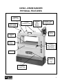
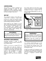
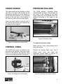
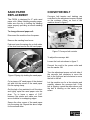
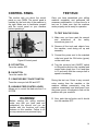
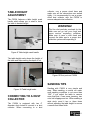
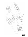
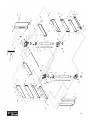
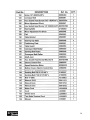
CX504 26” DRUM SANDER USER MANUAL TABLE OF CONTENTS General Safety Instructions .......................................................................... 3 Specific Safety Instructions........................................................................... 4 Features ....................................................................................................... 5 Physical Features ......................................................................................... 6 Unpacking .................................................................................................... 7 Setup ............................................................................................................ 7 Proper Grounding ......................................................................................... 7 Crank Handle................................................................................................ 8 Control Panel................................................................................................ 8 Pressure Rollers ........................................................................................... 8 Pressure Rollers ........................................................................................... 8 Sand Paper Replacement ............................................................................ 9 Conveyor Belt ............................................................................................... 9 Basic Controls ..............................................................................................10 Test Run .......................................................................................................10 Table Height Adjustment ..............................................................................11 Connecting to a Dust Collector .....................................................................11 Sanding Tips.................................................................................................11 Maintenance .................................................................................................12 Cleaning .......................................................................................................12 Lubrication ....................................................................................................12 Parts Diagram...............................................................................................13-16 Parts List ......................................................................................................17-20 Warranty .......................................................................................................21 2 GENERAL SAFETY INSTRUCTIONS Extreme caution should be used when operating all power tools. Know your power tool, be familiar with its operation, read through the owner’s manual and practice safe usage procedures at all times. ALWAYS read and understand the user manual before operating the machine. router bits, shaper heads, blades, knives or making other adjustments or repairs. CONNECT your machine ONLY to the matched and specific power source. NEVER leave a tool unattended while it is in operation. ALWAYS wear safety glasses respirators, hearing protection and safety shoes, when operating your machine. NEVER reach over the table when the tool is in operation. DO NOT wear loose clothing or jewelry when operating your machine. A SAFE ENVIRONMENT is important. Keep the area free of dust, dirt and other debris in the immediate vicinity of your machine. BE ALERT! DO NOT use prescription or other drugs that may affect your ability or judgment to safely use your machine. DISCONNECT the power source when changing drill bits, hollow chisels, ALWAYS keep blades, knives and bits sharpened and properly aligned. ALL OPERATIONS MUST BE performed with the guards in place to ensure safety. ALWAYS use push sticks and feather boards to safely feed your work through the machine. ALWAYS make sure that any tools used for adjustments are removed before operating the machine. ALWAYS keep the bystanders safely away while the machine is in operation. 3 CX504 - 26” DRUM SANDER SPECIFIC SAFETY INSTRUCTIONS MAKE SURE the sander is connected to the matched and specific power source instructed in the manual. ALL THE GUARDS must be in place while operating the sander to ensure safety. MAKE SURE before making any adjustments, the switch is in the “OFF” position and the cord is un-plugged from the power source. NEVER sand more than one work piece at a time on this sander. ALWAYS wear a dust mask and safety glasses while operating the sander. The tiny dust particles produced by the sander can cause serious health problems. ALWAYS inspect stock for staples, nails knots or any other foreign material before sanding. ALWAYS operate the sander in a wellventilated area and use a dust collection system for dust removal whenever possible. DO NOT wear loose clothing and jewelry while operating this sander. ALWAYS hold the work piece firmly when sanding. When not using the table, i.e. sanding free-hand, grip the work piece with both hands. KEEP YOUR WORK AREA CLEAN. Cluttered areas and workbenches increase the chance of accident. USE THE STOP FENCE when performing horizontal sanding on the belt sander. NEVER LEAVE the sander unattended while it is running. MAINTAIN AND SERVICE your sander regularly as instructed in the user manual. KEEP CHILDREN AWAY. All visitors should be kept at a safe distance from the work area. DO NOT force the sander. It will do the job better and will be safer at the operating rate for which it is designed. MAKE SURE you have read and understood all the safety instructions in the manual and you are familiar with your CX504 sander, before operating it. If you fail to do so, serious injury could occur. WARNING! The safety instructions given above can not be complete because the environment in every shop is different. Always consider safety first as it applies to your individual working conditions. 4 CX504 FEATURES MODEL CX504 – 26” DRUM SANDER As part of the growing line of Craftex CX-Series woodworking equipment, we are proud to offer CX504 a 26” Drum Sander. By following the instructions and procedures laid out in this user manual, you will receive years of excellent service and satisfaction. The CX504 is a professional tool and like all power tools, proper care and safety procedures should be adhered to. Motor ................................... 3-HP 220-Volt, 60-Hz, Single Phase Belt Feed Motor ................... 1/4-HP, 220V, Single Phase Maximum Sanding Width..... 26" Maximum Board Thickness . 12" Minimum Board Thickness .. 1/4" Minimum Board Length ....... 5" Feed Speed ......................... 3, 8, 12, 16 and 20 SFPM Number of Sanding Drums .. Two Drum Speed ........................ 1,600 RPM Dust Ports............................ Two 4" Each Dimensions.......................... Length 46" x Width 30-1/2" x Height 49" Weight ................................. 486 lbs Powder Coated Paint........... Yes Warranty .............................. 3 Years 5 CX504 –DRUM SANDER PHYSICAL FEATURES Sanding Head Cover Table Height Crank Handle 4" Dust Collection Ports Conveyor Belt ON/OFF Switch Variable Feed Control Knob ON/OFF Switch Conveyor Belt Depth Gauge Conveyor Belt Tracking Adjustment Screw & Nuts Table Craftex CX-Series Logo Powdered Coated Paint 6 UNPACKING The machine is properly packaged and shipped completely in crate for safe transportation. When unpacking, carefully inspect the crate and ensure that nothing has been damaged during transit. The sander should be wired with a plug having 3 prongs to fit a 3 prong grounded receptacle as shown in figure-1. Do not remove the grounding prong to fit it into a 2 pronged outlet. SETUP The unpainted surfaces of the tables are coated with a protective coating which prevents rust. Clean this protective coating using a rag with kerosene or painter thinner before starting assembling the machine. When setting up your machine, you will want to find an ideal spot where your planer will most likely be positioned most of the time. Consider your complete work environment as well as working comfortable with the sander before placing your machine in the ideal spot. WARNING! The CX504 is a heavy machine. Do not over-exert yourself. Use a fork truck or a lifting hook when lifting the machine. PROPER GROUNDING Grounding provides a path of least resistance for electric current to reduce the risk of electric shock. CX504 is for use on a normal 220 volt circuit. Make sure that the machine is connected to an outlet having the same configuration as the plug. If an adaptor plug is used, it must be attached to the metal screw of the receptacle. To prevent electrical hazards, have a qualified electrician ensure that the line is properly wired. Figure-1 220-Volts outlet for CX504 WARNING! Improper connection of the equipmentgrounding conductor can result in a risk of electric shock. Check with a qualified electrician if you are in doubt as to whether the outlet is properly grounded. It is strongly recommended not to use extension cords with your CX504. Always try to position your machine close to the power source so that you do not need to use extension cords. In case if you really find it necessary to use an extension cord, make sure the extension cord does not exceed 50-feet in length and the cord is 14-gauge to prevent motor damage. 7 CRANK HANDLE PRESSURE ROLLERS The crank handle can be installed on either right side or left side of the machine but we recommend installing the crank handle on the left side of the machine. If you install the handle on the right side of the machine, it will come in contact with the control panel. The CX504 features 3 pressure rollers located beside the drums. The pressure on the rollers is also effected by the drum height. Make sure the pressure rollers are adjusted according to the height of the drums. Attach the crank handle on the left side of the machine and secure it by tightening the set screw shown in figure-2. Figure-4 Pressure rollers Figure-2 Installing the crank handle To adjust the pressure rollers: CONTROL PANEL Make sure the cord is disconnected form the power source. The CX504 control panel is installed on the right side of the machine. Attach the control bracket to the machine and secure it using screws and washers provided. See figure-3. Remove the sanding head cover. Use a Philips screw driver and rotate the adjustment screws shown in figure-5 to adjust the pressure on the rollers. Figure-3 Installing the control panel Figure-5 Adjusting the pressure rollers 8 SAND PAPER REPLACEMENT The CX504 is designed for 6" wide sand paper rolls. When installing sanding paper, make sure the clip is holding the sanding paper properly providing a smooth sanding surface. CONVEYOR BELT Conveyor belt tension and tracking are controlled by the adjustment screws located on the conveyor rollers, on front of the machine shown in figure-7. To change the sand paper roll: Disconnect the machine from the power. Remove the sanding head cover. Push and open the spring clip on both sides of the drum and remove the old sand paper. Figure-7 Conveyor belt controls To adjust the conveyor belt: Loosen the lock nuts shown in figure-7. Connect the cord to the power outlet and turn the sander ON. Figure-6 Spring clip holding the sand paper Cut a pieces of 6" sand paper of the desired grit and fold the corner of the sand paper into the spring clamp. Get the help of an assistant to roll the drum and tightly spiral the sand paper onto the drum. Try to leave a space of 3/16" between the spirals and make sure there are no bubbles or overlapping edges. Turn the adjustment screws on both side of the conveyor belt clockwise to move the belt to the right and anti-clockwise to move the belt to the left. Let the machine run for a few minutes and carefully observe the conveyor belt. If the belt is slipping, repeat the steps above until the belt is tracking on the center of the rollers. Secure the other corner of the sand paper into the spring clip. Repeat the above steps for the second drum. 9 CONTROL PANEL This section tells you about the control panel on your CX504. The control panel is installed on the front side of the machine to the right. Make sure to familiarize yourself with the control panel on your machine before operating it. TEST RUN Once you have assembled your milling machine completely and performed the necessary adjustments, it is then time for a test run to make sure that the machine works properly and is ready for operation. TO TEST RUN THE CX504: 1. Make sure you have read the manual and understood all the safety instructions given in it. 2. Remove all the tools and objects from the machine, used during set up and assembly. Figure-8 Control panel A. OFF BUTTON Turns the sander OFF. B. ON BUTTON Turns the sander ON. C. CONVEYOR BELT ON/OFF SWITCH Turns the conveyor belt ON and OFF. D. VARIABLE FEED CONTROL KNOB Allows you to control the feed rate from 3 to 20 FPM. WARNING! Before starting the milling machine, make sure that you have read and understood the manual and you are familiar with the functions and safety features on this machine. Failure to do so may cause serious personal injury. 3. Connect the power cord to the matched outlet and push the ON button (green) on the switch box. 4. Turn the conveyor belt ON/OFF switch to ON position and turn the variable feed control knob slowly from 3 to 8 and then to 12 and verify that the conveyor belt is speed is increasing. During the test run if there is any unusual noise coming from the machine or the machine vibrates excessively, stop the machine immediately and disconnect from the power source. Investigate to find out the problem with your machine. 5. Now, push the red button and it should turn the machine OFF. 10 TABLE HEIGHT ADJUSTMENT The CX504 features a table height crank handle which allows you to raise or lower the table to desired height. collector, use a proper sized hose and make sure all the connections are sealed tightly. It is recommended to use a proper sized dust collector with the CX504 to ensure adequate dust collection. WARNING! The fine dust particles produced by the table saw can go into your lungs and cause serious respiratory problems. Make sure to wear a dust mask and connect the table saw to a proper dust collection system while operating it. Figure-9 Table height crank handle The table height scale shows the height of the table and helps setting the depth of cut. Figure-10 Dust ports on CX504 SANDING TIPS Figure-10 Table height scale CONNECTING TO A DUST COLLECTOR The CX504 is equipped with two 4" diameter dust chutes to connect to a dust collector. When connecting to a dust Sanding with CX504 is very simple and easy. When sanding, a normal cut under most sanding conditions is not more than 1/64". If you adjust the table to remove more than that, it can cause jamming, tear outs, belt slippage and etc. When sanding a wide stock, send it two or three times without adjusting the table height to ensure a smooth and clean finish. 11 MAINTENANCE During the life of your machine, you will need to practice some regular maintenance to keep your sander in peak performance condition. WARNING! Make sure the machine’s power switch is OFF and the cord is disconnected from the power source when installing / removing any part or servicing the sander. CLEANING The moisture from the wood dust remaining on the conveyor belt and other parts of the machine. The table and other unpainted surfaces of the machine should be cleaned and wiped after every use to make sure there is no moisture against bare metal surfaces. LUBRICATION The height adjustment screw shafts, located on either end of the machine must be well lubricated with grease at all times. Check your machine daily for the following before use: Damaged or worn sanding belt Damaged or worn power cord Loose mounting nuts, bolts, and parts Any other unsafe condition 12 13 14 15 16 17 18 19 20 WARRANTY CRAFTEX 3 YEARS LIMITED WARRANTY Craftex warrants every product to be free from defects in materials and agrees to correct such defects where applicable. This warranty covers three years for parts and 90 days for labour (unless specified otherwise), to the original purchaser from the date of purchase but does not apply to malfunctions arising directly or indirectly from misuse, abuse, improper installation or assembly, negligence, accidents, repairs or alterations or lack of maintenance. Proof of purchase is necessary. All warranty claims are subject to inspection of such products or part thereof and Craftex reserves the right to inspect any returned item before a refund or replacement may be issued. This warranty shall not apply to consumable products such as blades, bits, belts, cutters, chisels, punches etceteras. Craftex shall in no event be liable for injuries, accidental or otherwise, death to persons or damage to property or for incidental contingent, special or consequential damages arising from the use of our products. RETURNS, REPAIRS AND REPLACEMENTS To return, repair, or replace a Craftex product, you must visit the appropriate Busy Bee Tools showroom or call 1800-461-BUSY. Craftex is a brand of equipment that is exclusive to Busy Bee Tools. For replacement parts directly from Busy Bee Tools, for this machine, please call 1-800-461-BUSY (2879), and have your credit card and part number handy. All returned merchandise will be subject to a minimum charge of 15% for re-stocking and handling with the following qualifications. Returns must be pre-authorized by us in writing. We do not accept collect shipments. Items returned for warranty purposes must be insured and shipped pre-paid to the nearest warehouse Returns must be accompanied with a copy of your original invoice as proof of purchase. Returns must be in an un-used condition and shipped in their original packaging a letter explaining your reason for the return. Incurred shipping and handling charges are not refundable. Busy Bee will repair or replace the item at our discretion and subject to our inspection. Repaired or replaced items will be returned to you pre-paid by our choice of carriers. Busy Bee reserves the right to refuse reimbursement or repairs or replacement if a third party without our prior authorization has carried out repairs to the item. Repairs made by Busy Bee are warranted for 30 days on parts and labour. Any unforeseen repair charges will be reported to you for acceptance prior to making the repairs. The Busy Bee Parts & Service Departments are fully equipped to do repairs on all products purchased from us with the exception of some products that require the return to their authorized repair depots. A Busy Bee representative will provide you with the necessary information to have this done. 21