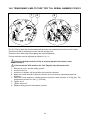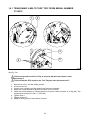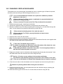
1
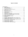
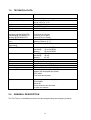
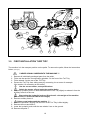
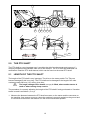
User manual and parts book Turf Tidy 3000 Serial number: Translation of the original user manual NOTE: IN THE INTERESTS OF SAFETY AND ACHIEVING THE BEST RESULT, IT IS VERY IMPORTANT THAT THIS MANUAL IS READ CAREFULLY BEFORE USING THE TURF TIDY. 1219 English 941,120,406 FOREWORD Congratulations with the purchase of your Turf Tidy. This manual must be read and understood in order to ensure safe and long-term operation of this Turf Tidy. Safe operation of this machine is not possible if the user is not fully familiar with the content of this manual. The Turf Tidy is not a stand-alone machine. It is the responsibility of the user to use the correct tractor. The user also has to perform safety-related checks on the tractor/Turf Tidy combination including sound level, user instructions and risk analysis. The general safety instructions will be covered on the next page. All users must be familiar with and apply these instructions. There is a registration card below, which must be sent back in order to process any future claims. This user manual contains numerous instructions, which are numbered in sequence. This working sequence must be adhered to. The pictogram indicates safety instructions. The pictogram indicates a tip and/or note. All information and technical specifications used were the most recent at the time of publication. Design specifications are subject to change without notice. This document is a translation of the original user manual. Original user manual (Dutch language) is available on request. WARRANTY CONDITIONS THIS TURF TIDY IS SUPPLIED WITH A WARRANTY FOR DEFECTS IN MATERIALS. THIS WARRANTY IS VALID FOR A PERIOD OF 12 MONTHS FROM THE DATE OF PURCHASE. TURF TIDY WARRANTIES ARE SUBJECT TO THE “GENERAL CONDITIONS FOR SUPPLY OF PLANT AND MACHINERY FOR EXPORT, NUMBER 188”, WHICH WERE PUBLISHED UNDER THE AUSPICES OF THE UNITED NATIONS ECONOMIC COMMISSION FOR EUROPE. REGISTRATION CARD Complete the table below for your own records: Machine serial number Dealer name Purchase date Comments 2 ! Fig. 1 SAFETY INSTRUCTIONS ! The Turf Tidy is designed for safe use. This is only possible if the safety instructions defined in this manual are observed in full. Read and understand (Fig. 1) the manual before proceeding to use the Turf Tidy. Failure to use the machine as described in the manual can result in injury and/or damage to the Turf Tidy. (1) Use of the machine requires operation by a competent user who has proficiently adjusted the machine to suit the surface for treatment. The manufacturer accepts no liability whatsoever for incompetent use and any damage arising from this; the user bears full responsibility for all risks arising from this. The timely and correct execution of the user, maintenance and repair instructions prescribed by the manufacturer also constitutes competent use. Inspect the area for treatment prior to using the Turf Tidy. Remove any free-standing obstacles and avoid irregularities. (2) The Turf Tidy has been manufactured in accordance with the latest technological knowledge and is safe for use. There is a risk of injury for the user and third parties if the machine is inexpertly operated, maintained or repaired. This must be avoided! Always use the Turf Tidy in combination with the correct tractor, as defined in the technical data. (3) All persons appointed by the owner as authorised to operate, perform maintenance on or repair the Turf Tidy must have read and fully understood the content of the operation manual and the Safety guidelines section in particular. The user is responsible for a safe Tractor/ Turf Tidy combination. The system as a whole must be tested for sound, safety, risk and ease of use. User instructions must also be drawn up. (4) The user has an obligation to check the Turf Tidy for visible damage and defects before use. Changes to the Turf Tidy (including the operation) that are detrimental to safety must be rectified immediately. For safety-based reasons, adapting or adding to the Turf Tidy (with the exception of factory approved changes) is not permitted as a rule. Modifications to the Turf Tidy will render the current CE marking ineffective and the person who performed the modifications is responsible for arranging new CE marking. Check the Turf Tidy for loose bolts / nuts / parts prior to each use. . . 3 Regularly check any hydraulic hoses and replace these if damaged or show signs of ageing. The replacement hoses must meet the manufacturer’s technical requirements. If present, the hydraulic system must be depressurised at all times before performing any activities on it. The turf Tidy may NEVER be used if the safety stickers are not present. NEVER crawl underneath the Turf Tidy. Tilt the turf Tidy if required. NEVER get off the tractor while the engine is still running. The Turf Tidy must be blocked to prevent it from lowering/driving off/sliding away when performing maintenance, adjustment and repair activities. Always switch off the tractor engine, remove the tractor ignition key and disconnect PTO shaft when performing maintenance, adjustment and repair activities. (Fig.2) Fig. 2 Only use original Turf Tidy parts for maintenance or repair activities in relation to the safety of the machine and user. Repairs to the Turf Tidy must be performed by authorised, technical staff. Maintain a repairs record. (5) In addition to the instructions in this user manual, the prevailing safety standards and Occupational Health and Safety regulations must be observed. The governing procedures of the traffic regulations apply to use on public highways. Transport of persons is not permitted! Do not use the Turf Tidy during hours of darkness, heavy rain/storm or on slopes with a gradient greater than 20 degrees. (6) All persons using the Turf Tidy must be familiar with all functions and operational elements of the machine prior to commencing the activities. Connect the Turf Tidy to the towing vehicle as stated in the instructions. (Injury hazard!) Ensure that you have a clear long distance view and clear sight of the immediate vicinity. 4 There are safety stickers (Fig. 6) on both sides of the Turf Tidy with an identical meaning. These safety stickers must be clearly visible and legible at all times and replaced when damaged. Persons must STAY out of the hazard zone of the Turf Tidy when operational, as there is a physical injury hazard due to moving parts (Fig. 3). Fig. 4 Fig. 3 Maintain a safe distance of at least 4 metres! (Fig. 4) Observe the permitted lifting capacity of the pulling vehicle. Wear appropriate clothing. Wear steel toecap safety shoes, long trousers, secure long hair and do not wear loose clothing. Beware of jamming hazard for body parts! (Fig. 5) Fig. 5 5 900.280.404 900.280.402 921.280.402 Fig. 6 (7) Locations of safety stickers. (Fig.6) Used oil/grease constitutes an environmental hazard and must be disposed in accordance with current regulations. 6 EU-DECLARATION We, Redexim BV Utrechtseweg 127 3702 AC Zeist, the Netherlands declare entirely under our own responsibility that the product: TURF TIDY WITH MACHINE NUMBER AS STATED ON THE MACHINE AND IN THIS MANUAL, to which this statement relates, is in accordance with the provisions of the Machine Directive 2006/42/EG. Zeist, 30.05.11 A.C. Bos Manager Operations & Logistics Redexim Holland 7 TABLE OF CONTENTS EU-DECLARATION ...................................................................................................................... 7 1.0 TECNICAL DATA .............................................................................................................. 9 2.0 GENERAL DISCRIPTION ................................................................................................. 9 3.0 FIRST INSTALLATION TURF TIDY .............................................................................. 100 3.1 TOW BAR INSTALLATION ........................................................................................... 111 4.0 CONNECTING / DISCONNECTING TURF TIDY ......................................................... 111 5.0 THE PTO SHAFT .......................................................................................................... 122 5.1 LENGTH OF THE PTO SHAFT .................................................................................... 122 5.2 USING THE PTO SHAFT ................................................................................................ 13 6.0 TRANSPORTING THE TURF TIDY ................................................................................ 13 7.0 WORKING SPEED .......................................................................................................... 13 8.0 USING THE TURF TIDY ................................................................................................. 14 9.0 WORKING DEPTH ADJUSTMENT ................................................................................ 15 9.1 WORKING DEPTH ADJUSTMENT USING THE FRONT ROLLER ............................... 15 9.2 WORKING DEPTH ADJUSTMENT USING THE FRONT WHEELS .............................. 16 10.0 START / STOP PROCEDURE TURF TIDY .................................................................... 17 11.0 EMPTYING THE COLLECTION TRAY ........................................................................... 18 12.0 TROUBLE SHOOTING ................................................................................................... 18 13.0 MAINTENANCE .............................................................................................................. 19 13.1 POSITION OF LUBRICATING POINTS .......................................................................... 19 14.0 TENSIONING V-BELTS TURF TIDY TILL SERIAL NUMBER C310212 ........................ 21 14.1 TENSIONING V-BELTS TURF TIDY FROM SERIAL NUMBER C310212 ..................... 22 14.2 CHANGING / REPLACING BLADES .............................................................................. 23 14.3 REPLACING HARROW / MOWING ROTOR WITH SWEEPING ROTOR ..................... 26 15.0 OPTIONAL EXTRAS : HARROWING BLADES .............................................................. 28 15.1 OPTIONAL EXTRAS : FLAIL BLADES ........................................................................... 28 15.2 OPTIONAL EXTRAS : BRUSHKIT .................................................................................. 28 15.3 OPTIONAL EXTRAS : FRONT WHEELS ....................................................................... 29 15.4 OPTIONAL EXTRAS : DOUBLE REAR WHEELS .......................................................... 30 8 1.0 TECHNICAL DATA Model 3000 Operational width Dimensions (LxWxH) 1800mm (71”) 3604mm x 2223mm x 1807mm 141.8” x 87.5” x 71.3” 1275 Kg (2805lbs) 3.0m3 (105 cu.ft) 2,170mm (85”) Weight Collection tray capacity Tilting height collection tray Working speed Sweeping @ 300 RPM PTO Harrowing @ 540 RPM PTO Mowing @ 540 RPM PTO Operational depth (With sharp blades) Distance between the blades (Harrowing) PTO shaft RPM Recommended tractor Hydraulic tractor connector Tractor connector Tyre pressure Gearbox oil Lubricating grease Standard parts Optional extras 2.0 1-10 km/h (0.6-6 mph) 1-5 km/h (0.6-3 mph) 1-2 km/h (0.6-1.5 mph) Harrowing: -30mm (1.2”) Mowing: +80mm (3.1”) 20mm / 40mm (0.8”/ 1.6”) Sweeping: Up to 300 RPM Harrowing: Up to 540 RPM Mowing: Up to 540 RPM Sweeping: 25 HP Harrowing: 45 HP Mowing: 45 HP 2 single acting valve Towing ring and pin 0.8 – 1.8 bar (11.6 – 26 psi) 1.7l (0.45 gallon) SAE 80W90 EP2 -Harrowing blade set 2mm (0.08”) + blades with integrated tips (fitted) -PTO shaft -Tool case and manual -Harrowing blades 3mm (0.11”) -Flail blades. -Brush kit -Front wheel set for the head. -2 extra rear wheels GENERAL DESCRIPTION The Turf Tidy is a combination machine for harrowing/mowing and sweeping surfaces. 9 2 5 7 1 4 3 6 3 4 Fig. 6 3.0 FIRST INSTALLATION TURF TIDY The machine is in the transport position on the pallet. To remove the pallet, follow the instructions below: (see Fig.6) !! NEVER CRAWL UNDERNEATH THE MACHINE !! 1. 2. 3. 4. Remove all individually packaged parts from the pallet. Fit the tow bar and the corresponding spindles 1 to the front of the Turf Tidy. Fit the wheels 2 to the rear of the Turf Tidy. Prevent the Turf Tidy from sliding away by connecting it to a tractor for example. (See section 4.0 connecting to the tractor) Use the correct tractor; see specifications. Switch the tractor off and apply the parking brake. 5. Position a hydraulic jack 3 on both sides and lift the Turf Tidy slightly to release it from the auxiliary frame 4 at the rear. Ensure that the hydraulic jack can lift at least 2 x the weight of the machine. (See section 1.0 technical data for the weight) 6. Remove auxiliary frame 4. !! Never crawl underneath the machine !! 7. Rotate the spindles 6 slightly until the front of the Turf Tidy is lifted slightly. 8. Remove the nuts and bolts 5. 9. Lower the hydraulic jacks until the rear wheels 2 are on the ground. 10. Remove the pallet 7. 10 3.1 TOW BAR INSTALLATION Fig. 7 The Turf Tidy is connected to the tractor using the tow bar The tow bar can be used as both an upwards and downwards tow bar, subject to the position of the connector on the tractor. (Fig. 7) 4.0 CONNECTING / DISCONNECTING TURF TIDY Check procedure before proceeding to connect the Turf Tidy. Check the Turf Tidy for visual damage and repair this damage if the safe operation of the machine is no longer guaranteed. Check that all nuts and bolts are properly secured. Check that all safety guards and all safety stickers are in place on the machine and are not damaged. The machine must NEVER be used without these. The connection method is as follows: (Fig. 8) 1. Carefully reverse the tractor into a suitable position for connecting the tow bar to the tractor. !! Ensure that that tractor is properly blocked and cannot move independently !! !! Switch the tractor engine off before getting off the tractor !! 2. Connect the Turf Tidy to the tractor by placing the pin in the connector of the tractor through the tow bar 1 of the Turf Tidy and securing this. 3. Connect the hydraulic hoses 2 to the tractor. The narrow hose is connected to the head and the wide hose to the collection tray. 4. Position the disconnecting rope 3 from the head to the cabin for safety reasons. 5. Connect the PTO shaft 4 between the Turf Tidy and the tractor. (See section 5.0 for the correct length of the PTO shaft) 6. Retract the height adjustable leg. 7. Expand or retract the spindles 7 to adjust the upper side of the frame 6 of the Turf Tidy until it is parallel with the surface. Disconnecting takes place in reverse order. 11 6 8 7 4 1 3 2 Max. 30° A Max.3 0° m (1 300m B in. 2") m Fig.8 5.0 THE PTO SHAFT The PTO shaft is a very important part. It provides the drive from the tractor and ensures, if correctly maintained and installed, safe use of the machine. The PTO shaft has dedicated CE certification. Read the PTO shaft manual, which can be found on the actual PTO shaft. 5.1 LENGTH OF THE PTO SHAFT The length of the PTO shaft is very important. The drive on the tractor and/or Turf Tidy can become damaged if this is too long. The PTO shaft can be damaged if the length of the tube overlap exceeds 300 mm (12") at any given time. The length changes when head 8 (see Fig.8) is lifted, when another tractor is used or when turning sharp corners. The procedure for correctly adjusting the length of the PTO shaft if newly purchased or if another tractor is used is as follows: (see Fig.8) 1. Measure the distance between the PTO shaft connector on the tractor and the connector on the machine, from groove to groove, when the machine is correctly angled on the ground and is connected to the tractor and head 8 is in the most unfavourable position. 12 2. Measure the length B of the PTO shaft when in the shortest position from locking pin to locking bolt. 3. Split the PTO shaft into two parts and remove the safety guards from both ends. 4. Both the ends of the tubes and the safety guards must be shortened. (B-A) + 150 mm (3”). 5. Burr all parts, use a little grease and reassemble all parts. 6. Secure the other end of the PTO shaft to the tractor. 7. Check the tube overlap. Never use the machine if the PTO shaft safety guard is damaged. Replace this first! 5.2 USING THE PTO SHAFT Correct use of the PTO shaft requires checks of the following items: 1. The angle of the centres of rotation may never exceed 30 degrees when operational. 2. The centres of rotation must always be aligned. 3. The minimum tube overlap is 300 mm. 4. Never use the machine if the PTO shaft safety guard is damaged. 5. See maintenance section for lubrication. 6.0 TRANSPORTING THE TURF TIDY The user is responsible for transporting the Turf Tidy behind the tractor on public highways. Look into national legislation for the regulations. The maximum speed across open fields, with the machine elevated, is 15 km/hour (9.3 mph), circumstances permitting; driving at higher speeds constitutes a potential hazard for the driver/bystanders and may even cause damage to the machine. 7.0 WORKING SPEED The maximum working speed for the Turf Tidy is 5 km/h (3.1 mph), however, the user will have to determine the correct speed based on the surface to be treated in combination with the desired working depth. This is directly related to the power output, the higher the output the lower the forward speed. The following may occur in the event of excessive power output transfer: The V-belts start slipping / burning, which can result in broken V-belts. The blades wear more rapidly. The brackets for the blades wear more rapidly. The machine design is robust, therefore overloading is not easily noticed. However, it is important that the power output requirements are assessed. Take the following into consideration: When harrowing: What is the working depth? The required power output increases with the depth. How hard is the surface? The required power output increases with the hardness. What is the working speed? The wear and tear and power output increases with the speed. 13 When sweeping: Weight and quantity of material for sweeping? The required power output increases with the weight. What is the working speed? The wear and tear and power output increases with the speed. When mowing: How long is the grass? The required power output increases with the length. What is the working speed? The wear and tear and power output increases with the speed. The following applies in general: the working speed must be lowered as the load increases. See the specifications in section 1.0 for guidelines. 8.0 USING THE TURF TIDY The following checks must be made before proceeding to use the Turf Tidy at a site: 1. 2. 3. 4. 5. 6. 7. 8. 9. Are there any freestanding objects on the field? Remove these first. Are there slopes? This machine is only suitable for use on slopes with a maximum gradient of 20 degrees. Always work from the top to the bottom. Are there are any airborne objects in the area, such as balls, which will distract the user from the task at hand? If so, the Turf Tidy may NOT be used. Is there a slipping or sagging hazard? If yes, postpone the activities until the conditions improve. If the surface is wet, postpone the activities until conditions improve. Do not make any sharp turns as this may cause damage to the surface. Only tilt the collection tray when on a solid, level surface. Never drive the Turf Tidy when the collection tray is not lowered. During transport: Ensure that the head is facing upwards and is blocked to prevent sagging. 14 9.0 WORKING DEPTH ADJUSTMENT The machine is fitted with a front roller as standard, but can also be supplied with front wheels (prod. no. 241.180.008). These enable turning corners with the machine when flail mowing and/or sweeping. Therefore, there are 2 ways to adjust the working depth of the machine. 1. By adjusting the front roller. 2. By adjusting the optional front wheels. 4 3 A 2 B 1 Fig. 9 9.1 ADJUSTING WORKING DEPTH USING THE FRONT ROLLER Proceed as follows to adjust the working depth: (See Fig.6) !! NEVER CRAWL UNDERNEATH THE MACHINE !! Switch the tractor off and apply the parking brake. Ensure that the machine is properly blocked and cannot move independently. If wind vanes (See fig. 9 item 4) have been fitted, never increase the depth to ensure that the wind vanes remain above the surface. !! If this is not observed, the surface and the machine can be seriously damaged!! !! Adjust the working depth carefully; if the setting is too deep the machine and the surface can be seriously damaged !! 1. Rotate the spindles 1 on both sides to the desired working depth B and align on both sides. Use the indicator stickers on the spindles for this. 2. Loosen the bolts 2 on both sides of the machine and adjust the rear roller using nuts 3 until the distance above the ground A is 10mm (0.4") and align on both sides. indicator stickers on the spindles for this. This prevents the grass layer being removed by the head. 3. Secure the nuts 3 and bolts 2 properly. 4. Run a test strip to verify that the correct working depth has been achieved. 15 Use the 9.2 ADJUSTING WORKING DEPTH USING THE FRONT WHEELS Proceed as follows to adjust the working depth: (See Fig.10) 2 4 3 5 1 Fig. 10 1. Fully lift the head by operating the hydraulic output of the tractor and ensure that it is properly positioned in the transport securing device 1 and is fully blocked to prevent sagging. !! NEVER CRAWL UNDERNEATH THE MACHINE !! Switch the tractor off and apply the parking brake. Ensure that the machine is properly blocked and cannot move independently. If wind vanes (See fig. 9 item 4) have been fitted, never increase the depth to ensure that the wind vanes remain above the surface. !! If this is not observed, the surface and the machine can be seriously damaged!! !! Adjust the working depth carefully; if the setting is too deep the machine and the surface can be seriously damaged !! 2. Remove clip 2 and remove the wheels 3 by sliding them downwards. 3. Adjust to the required height by using various combinations of spacing rings. 4. Slide the wheels 3 back into the centre pin 5 and secure using the clip 2. 5. (See Fig.9) Loosen the bolts 2 on both sides of the machine and adjust the rear roller using nuts 3 until the distance above the ground A is 10mm (0.4") and align on both sides. Use the indicator stickers on the spindles for this. This prevents the grass layer being removed by the head. 6. (See Fig.9) Secure the nuts 3 and bolts 2 properly. 7. Run a test strip to verify that the correct working depth has been achieved. 16 10.0 START/STOP PROCEDURE TURF TIDY The start procedure is VERY important. The surface to be treated /machine can be seriously damaged if this procedure is not executed as described below. 2 3 1 Fig. 11 The start procedure is as follows: : (See Fig.11) 1. Thoroughly check the Turf Tidy for loose parts and check that all parts are working properly. !! If loose parts are discovered or incorrectly functioning parts, the problem must be rectified before using the Turf Tidy !! 2. Drive to the site to be treated. 3. Activate the hydraulic output of the tractor to lift head 1, pull the cord 2 to release the transport securing device 3. 4. Lower head 1 until the blades are just above the ground. 5. If required, adjust the working depth of the machine as described in section 9.0. 6. Put the tractor into the correct gear. 7. Adjust the tractor engine to approximately 1200 RPM and activate the PTO shaft. 8. Gently lower head 1 until the front roller or wheels of the head touch the ground. 9. Drive forwards and increase the RPM up to the RPM of the PTO shaft reaches the required level. (Max 540 rpm when harrowing and mowing and max. 300 rpm when sweeping.) 10. For the first strip: Check whether the correct working depth has been achieved after a few metres, adjust the working depth as described in section 9.0. where required Stopping takes place as follows: 1. Lower the engine RPM to approximately 1200 RPM. 2. Lift head 1 slightly by operating the hydraulic output of the tractor. 3. Switch off the PTO shaft as soon as the blades are no longer touching the ground and allow the rotor to stop turning. 4. Fully lift head 1 and ensure that it falls into the transport securing device. 5. Proceed to the following site and repeat procedure. !! Drive in straight lines where possible, in relation to potential damage to the surface and/or machine !! !!T he head must be lifted during transport and in the transport securing device !! 17 11.0 EMPTYING THE COLLECTION TRAY 1. Drive to the location where the collection tray is emptied. !! Only tilt the collection tray when on a solid, level surface !! !! Ensure that there are no persons in the hazard zone of the machine !! 2. Activate the hydraulic outlet of the tractor to raise the collection tray and to tilt to empty it. 3. Lower the collection tray again when empty by operating the hydraulic outlet of the tractor. !! Do not drive off until the collection tray has been fully lowered!! 12.0 TROUBLESHOOTING Problem Machine vibrates Possible cause Solution - Missing blades. Rotor out of balance - - PTO shaft damaged. Surface too hard. - - Rotor bearings defective. PTO shaft RPM too high. Working speed too high. - - Machine depth setting is too deep. V-belts slipping - Overload. - - Obstacles in soil. - Crunching sound when machine is operational - Bearings are worn. - Replace the defective bearings. Not enough material removed. - Working depth setting is not deep enough. Excessive driving speed. Blades worn. V-belts slipping. - Increase depth setting on machine Decrease driving speed Replace blades. Adjust V-belts or replace where necessary. Blade rotor does not rotate. Blades / securing clips break. - - 18 - - Check and replace. Check for damage and/or material wrapped around the rotor Check and repair or replace. Postpone work until conditions improve. Check and replace. Adjust RPM. Adjust working speed Decrease depth setting on machine Adjust V-belts. Check ground conditions and adjust the working depth or postpone until conditions improve. Remove obstacles. Lower PTO shaft RPM. Lower working speed. Problem Poor field appearance after treatment Possible cause Machine depth setting is too deep. Surface too moist. - - Blades worn Driver did not drive in a straight line. - - Poor quality grass. - - Blunt blades. - - Rough ground. - - Rotor out of balance - - Damage to the grass Unstable behaviour head Solution - Decrease depth setting on machine Postpone work until conditions improve. Replace blades. Drive in a straight line while operational. Decrease working depth. Lower working speed. Replace blades. Use the front roller, not the wheels. See “machine vibrates”. 13.0 MAINTENANCE 13.1 POSITION OF LUBRICATING POINTS 2 3 1 2 1 2 Fig. 12 19 Time schedule/frequency Prior to each use Checkpoint/Lubrication point - Check for loose bolts / nuts. - - Presence and legibility of the safety stickers. (Fig. 5) Check the tension of the Vbelts. - - Clean the machine. - - Lubricate the rotor and gearing bearings. (1) (See fig.12) - Caution required with the bearings if a high pressure washer is used. 1 shot EP2 - Grease all lubricating points (1&2) (See fig.12 ) Check the roller bearings and the drive line. Check for loose bolts / nuts. Check the tension of the Vbelts. - 1 shot EP2. - Check and replace if necessary. Tighten the loose nuts / bolts. Adjust the tension of the Vbelts. Or replace the V-belts where necessary. Check the roller bearings and the drive line. Clean the sliding tubes (3) and grease them. Check for loose bolts / nuts. - Check the hydraulic components are working properly and for any damage. Check the tension of the Vbelts. - - Adjust the tension of the Vbelts. Or replace the V-belts where necessary. - Check for oil leaks. Check the oil level in the gearbox. - Repair or replace. Use SAE 80W90 for the gearbox. - Replace the oil in the gearbox. - Use 1.7l (0.45 gallon) SAE 80W90 - After every use After the first 20 operational hours (new or repaired) - After every 100 operation hours or annually - - After every 500 operational hours Method - - - Tighten the loose bolts / nuts with the correct moment. Replace if not present/damaged. Adjust the tension of the Vbelts. Or replace the V-belts where necessary. Use EP2 lubricating grease Replace if necessary. Use lubricating grease Tighten the loose nuts / bolts. Check and replace if necessary. Used oil / grease constitutes an environmental hazard and must be disposed in accordance with current regulations. 20 14.0 TENSIONING V-BELTS TURF TIDY TILL SERIAL NUMBER C310212 1 2 4 3 5 A Fig.13 The Turf Tidy is fitted with an adjustable belt tensioner that maintains the stress on the V-belts. The drive line will be subjected to wear and tear through use. Therefore, the V-belts may start slipping and require tightening. The belt tensioner can be adjusted as follows (See Fig. 13): !! Ensure that that tractor/Turf Tidy is properly blocked and cannot move independently !! !! Ensure that the PTO shaft on the Turf Tidy has been disconnected !! 1. 2. 3. 4. 5. 6. 7. 8. Remove all nuts 1 and the safety guard 2. Loosen lock nut 3. Loosen nut 4 slightly until the tension has just been released. Adjust nut 5 and use this to adjust the tension on the V-belts by repositioning the belt tensioner. Check the V-belt tension by exerting pressure on point A with a tension of 3.5 kg (lbs). The compression must be 4.5 mm (”). (Per belt) Tighten nut 4. Tighten lock nut 3. Replace safety guard 2 and replace all nuts 1. 21 14.1 TENSIONING V-BELTS TURF TIDY FROM SERIAL NUMBER C310212 1 2 A 3 5 4 Fig.13a See fig. 13a !! Ensure that that tractor/Turf Tidy is properly blocked and cannot move independently !! !! Ensure that the PTO shaft on the Turf Tidy has been disconnected !! 1. 2. 3. 4. 5. Remove all nuts 1 and the safety guard 2. Loosen lock nut 3. Loosen nuts 4 slightly until the tension has just been released. Adjust nut 5 and use this to adjust the tension on the V-belts. Check the V-belt tension by exerting pressure on point A with a tension of 3.5 kg (lbs). The compression must be 4.5 mm (”). (Per belt) 6. Tighten nuts 4. 7. Tighten lock nut 3. 8. Replace safety guard 2 and replace all nuts 1. 22 14.2 CHANGING / REPLACING BLADES The blades have to be exchanged if the blades are worn or another type of blade is required; this takes place according to the following procedure (See fig.14): !! It is recommended that all blades are replaced in relation to potential imbalance in the rotor !! !! Ensure that the Turf Tidy / tractor combination is properly blocked and cannot move independently !! !! Ensure that the PTO shaft on the Turf Tidy has been disconnected !! 1. Remove the securing pin 1 and clip on both sides. 2. Activate the hydraulic outlet of the tractor to raise and tilt the collection tray. 3. Block the collection tray from tilting by placing the securing pin 1 on both sides through the hole 2 in the collection tray and tube and securing it with the clip. !! Ensure that the blocking hook 10 is inside the tube !! !! Ensure that the Turf Tidy is properly blocked and cannot move independently !! 4. Remove bolts 3 from the rear hatch 4. 5. Raise the rear hatch 4 and secure using the hooks 5. 6. Remove the clip 6 from the brackets 7 and remove the brackets from the rotor together with the blades 8 and blades with integrated tips 9. !! Take care! The blades may be sharp !! A number of brackets are fitted close to the side plates of the head, the cover plate 11 can be moved for the removal of these. !! After fitting the blades, return the cover plate 11 to the original position so that the hole in the side plate is covered !! 7. Replace the blades 8 and /or the blades with integrated tips 9 and place the bracket 7 with the blades back onto the rotor and secure this using the clip 6. See fig. 15 for the correct position of the brackets and blades. The direction of the bracket opening corresponds to the number on the rotor. !! Do not use flail blades 9 if blades with integrated tips are used for mowing !! 8. Close the rear hatch 4 after the blades have been replaced and secure using the bolts 3. !! Beware of jamming hazard when closing the rear hatch !! 9. Remove the securing pins 1 on both sides and lower the collection tray by operating the hydraulic output of the tractor. 10. Insert the securing pin into the hole 12 on both sides and secure using the clip. 23 1 12 2 10 5 11 4 3 8 9 9 7 6 Fig.14 24 Rotation direction Row number placement on left side rotor. Rotation direction Blade hook closed side facing outwards Blade hook closed side facing inwards for row 1, 3, 4, 12 (for 20mm slit distance) for row 6, 7, 9, 10 (for 20mm slit distance) for row 1, 3, 4, 6, 7, 9, 10, 12 (for 40mm slit distance) Wind vanes placed on row 2, 5, 8, 11 Fig.15 25 14.3 REPLACING HARROW / MOWING ROTOR WITH SWEEPING ROTOR In addition to harrowing and mowing functions, the Turf Tidy machine also has a sweeping function. As the RPM for a sweeping machine is lower than for a harrowing machine, a different rotor must be fitted to the Turf Tidy and the drive sheave has to be reversed. This takes place according to the following procedure (See Fig.16): !! Ensure that the Turf Tidy / tractor combination is properly blocked and cannot move independently !! !! Ensure that the PTO shaft on the Turf Tidy has been disconnected !! 1. Remove the securing pin 1 and clip on both sides. 2. Activate the hydraulic outlet of the tractor to raise and tilt the collection tray. 3. Block the collection tray from tilting by placing the securing pin 1 on both sides through the hole 2 in the collection tray and tube and securing it with the clip. !! Ensure that the blocking hook 17 is inside the tube !! !! Ensure that that tractor/Turf Tidy is properly blocked and cannot move independently !! 4. If necessary, lower head 3 by activating the hydraulic outlet of the tractor. 5. Remove the nuts 4 and the safety guard 5. 6. Remove the v-belts 8. 7. Remove the large drive sheave 9 by releasing the taper lock tube 10. 8. Remove the small drive sheave 11 by releasing the taper lock tube 12. 9. Release the grease nipple bracket 19. 10. Loosen the bolts 21 slightly on both sides of the machine until the tension has just been released. 11. Remove the bolts 13 on both sides of the machine. 12. Lift head 3 slightly by activating the hydraulic output of the tractor. 13. Remove the rotor 14 by sliding it downwards. 14. Lift head 3 slightly further by activating the hydraulic output of the tractor. 15. Remove the rotor 14. 16. Fit the brush rotor 15 and slide this upwards until it reaches the stop 16. 17. Fix the rotor in place on both sides of the machine using the bolts 13. 18. Securely tighten the bolts 21 on both sides of the machine. 19. Fit the bracket 19 and fix the grease nipple into place. 20. Slide the large drive sheave 9 with the taper lock tube 10 onto the brush rotor 15. 21. Slide the small drive sheave 11 with the taper lock tube 12 onto the drive shaft. 22. Fit the v-belts 8. 23. Align the drive sheaves until they are fully in line and the v-belts are positioned centrally on the belt tensioner 20. Secure the drive sheaves onto the axles. 24. Tension the v-belts as described in section 14.0. 25. Turn the rotor a number of times and ensure that all parts are properly secured and aligned. 26. Fit the safety guard 5 and secure using bolts 14. 27. Remove the securing pins 1 on both sides and lower the collection tray by operating the hydraulic output of the tractor. 28. Insert the securing pin into the holes 18 on both sides and secure using the clip. 29. The machine is now ready to use. 26 1 18 2 17 3 4 5 9 10 21 19 11 12 16 13 8 14 11 12 19 15 13 21 9 10 8 Fig.16 27 15.0 OPTIONAL EXTRAS: HARROWING BLADES The Turf Tidy has 2mm (0.08”) thick harrowing blades as standard. 3mm (0.11”) thick harrowing blades can also be fitted if desirable. These can be ordered under product no. 35000-075, see the parts manual for quantities. The harrowing blades must always be used with the blades with integrated tips 3 to ensure the material is properly grasped. (See fig. 17) The assembly of the blades is described in section 14.1. 3 1 3 2 Fig.17 15.1 OPTIONAL EXTRAS: FLAIL BLADES The Turf Tidy can also be used as a flail mower mower, 2 types of rake blades are available for this application. (See fig. 17) 1. Standard flail blades prod. no. 341.305.120. 2. Back to back flail blades prod. no. 341.302.120. See parts manual for quantities. The assembly of the blades is described in section 14.1. 15.2 OPTIONAL EXTRAS: BRUSH KIT The Turf Tidy can also be used as a sweeping machine. A brush kit must be fitted to convert the machine. The brush kit can be ordered under prod. no. 241.180.002. See parts manual for individual parts of kit. The conversion method is described in section 14.2. The sweeping option is suitable for sweeping grass and hard surfaces. The standard front roller is recommended for sweeping grass surfaces and the optional front wheels for hard surfaces. !! The PTO speed must be reduced to 300 rpm to prevent damage to the machine and the surface !! !! Pay particular attention to the working depth settings. Incorrect depth settings can cause serious damage to the surface and the machine !! 28 15.3 OPTIONAL EXTRAS: FRONT WHEELS The Turf Tidy head can be fitted with an optional front wheel set. These can be used to adjust the height instead of the standard front roller for the mowing and sweeping applications. Sharp turns can be made by using front wheels instead of the front roller. The front wheels can be ordered in a kit under prod. no. 241.180.008. See parts manual for individual parts of kit. !! Do not make any sharp turns with the Turf Tidy with the front wheel set mounted. This can result in serious damage to the surface and/or machine !! The front wheels are mounted as follows: (See fig. 18) Fig.18 !! Ensure that that tractor/Turf Tidy is properly blocked and cannot move independently !! 1. Lift the head slightly by activating the hydraulic output of the tractor so that the wheels can be mounted. 2. Fit the front wheels to the head on both sides of the machine using supplied nuts and bolts. 3. Check the tyre pressure: this should be 1-2 bar (14-22 psi). 29 15.4 OPTIONAL EXTRAS: DOUBLE REAR WHEELS An extra set of rear wheels can be fitted to the Turf Tidy, so that fewer impressions are left behind on the grass. The double rear wheels can be ordered in a kit under prod. no. 241.180.006. See parts manual for individual parts of kit. The rear wheels are mounted as follows: (See fig. 19) 3 2 2 1 1 6 4 A A 5 2 3 1 Fig.19 !! Ensure that the Turf Tidy / tractor combination is properly blocked and cannot move independently !! 1. Place a hydraulic jack 1 at the rear of the machine on both sides and raise the Turf Tidy slightly until the wheels are released. Ensure that the hydraulic jack can lift at least 2 x the weight of the machine. (See section 1.0 technical data for the weight) !! Never crawl underneath the machine !! 2. Remove the wheels 2 on both sides. 3. Remove the nuts and bolts 3 and remove the rear axle 4. 4. Remove the short axles 5 from the kit and centre these in respect of the tube 6, so that the distances A are equal. 5. Tighten the nuts and bolts 3. 6. Fit wheels 2 to the rear axle and tighten. 7. Check that the wheels 2 can turn freely. 8. Lower the hydraulic jacks 1 until the wheels 2 are on the ground. 30