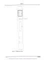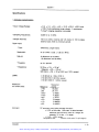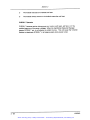
1
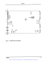
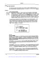
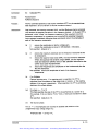
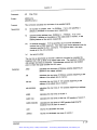
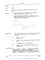
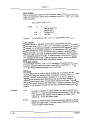
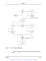
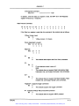
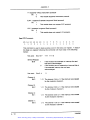
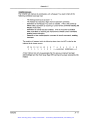
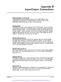
Artisan Technology Group is your source for quality
new and certified-used/pre-owned equipment
• FAST SHIPPING AND
DELIVERY
• TENS OF THOUSANDS OF
IN-STOCK ITEMS
• EQUIPMENT DEMOS
• HUNDREDS OF
MANUFACTURERS
SUPPORTED
• LEASING/MONTHLY
RENTALS
• ITAR CERTIFIED
SECURE ASSET SOLUTIONS
SERVICE CENTER REPAIRS
Experienced engineers and technicians on staff
at our full-service, in-house repair center
WE BUY USED EQUIPMENT
Sell your excess, underutilized, and idle used equipment
We also offer credit for buy-backs and trade-ins
www.artisantg.com/WeBuyEquipment
InstraView REMOTE INSPECTION
LOOKING FOR MORE INFORMATION?
Visit us on the web at www.artisantg.com for more
information on price quotations, drivers, technical
specifications, manuals, and documentation
SM
Remotely inspect equipment before purchasing with
our interactive website at www.instraview.com
Contact us: (888) 88-SOURCE | [email protected] | www.artisantg.com
User Manual
VX4240
Waveform Digitizer/Analyzer Module
070-9140-06
This document supports firmware version 1.00
and above.
Warning
The servicing instructions are for use by qualified
personnel only. To avoid personal injury, do not
perform any servicing unless you are qualified to
do so. Refer to the Safety Summary prior to
performing service.
Artisan Technology Group - Quality Instrumentation ... Guaranteed | (888) 88-SOURCE | www.artisantg.com
Copyright Tektronix, Inc. 1991, 1994. All rights reserved.
Tektronix products are covered by U.S. and foreign patents, issued and pending. Information in this publication supercedes
that in all previously published material. Specifications and price change privileges reserved.
Printed in the U.S.A.
Tektronix, Inc., P.O. Box 1000, Wilsonville, OR 97070–1000
TEKTRONIX and TEK are registered trademarks of Tektronix, Inc.
Artisan Technology Group - Quality Instrumentation ... Guaranteed | (888) 88-SOURCE | www.artisantg.com
WARRANTY
Tektronix warrants that this product will be free from defects in materials and workmanship for a period of three
(3) years from the date of shipment. If any such product proves defective during this warranty period, Tektronix,
at its option, either will repair the defective product without charge for parts and labor, or will provide a
replacement in exchange for the defective product.
In order to obtain service under this warranty, Customer must notify Tektronix of the defect before the expiration
of the warranty period and make suitable arrangements for the performance of service. Customer shall be
responsible for packaging and shipping the defective product to the service center designated by Tektronix, with
shipping charges prepaid. Tektronix shall pay for the return of the product to Customer if the shipment is to a
location within the country in which the Tektronix service center is located. Customer shall be responsible for
paying all shipping charges, duties, taxes, and any other charges for products returned to any other locations.
This warranty shall not apply to any defect, failure or damage caused by improper use or improper or inadequate
maintenance and care. Tektronix shall not be obligated to furnish service under this warranty a) to repair damage
resulting from attempts by personnel other than Tektronix representatives to install, repair or service the product;
b) to repair damage resulting from improper use or connection to incompatible equipment; or c) to service a
product that has been modified or integrated with other products when the effect of such modification or
integration increases the time or difficulty of servicing the product.
THIS WARRANTY IS GIVEN BY TEKTRONIX WITH RESPECT TO THIS PRODUCT IN LIEU OF
ANY OTHER WARRANTIES, EXPRESSED OR IMPLIED. TEKTRONIX AND ITS VENDORS
DISCLAIM ANY IMPLIED WARRANTIES OF MERCHANTABILITY OR FITNESS FOR A
PARTICULAR PURPOSE. TEKTRONIX’ RESPONSIBILITY TO REPAIR OR REPLACE DEFECTIVE
PRODUCTS IS THE SOLE AND EXCLUSIVE REMEDY PROVIDED TO THE CUSTOMER FOR
BREACH OF THIS WARRANTY. TEKTRONIX AND ITS VENDORS WILL NOT BE LIABLE FOR ANY
INDIRECT, SPECIAL, INCIDENTAL, OR CONSEQUENTIAL DAMAGES IRRESPECTIVE OF
WHETHER TEKTRONIX OR THE VENDOR HAS ADVANCE NOTICE OF THE POSSIBILITY OF
SUCH DAMAGES.
Artisan Technology Group - Quality Instrumentation ... Guaranteed | (888) 88-SOURCE | www.artisantg.com
Contacting Tektronix
Product
Support
For application-oriented questions about a Tektronix
measurement product, call toll free in North America:
1-800-TEK-WIDE (1-800-835-9433 ext. 2400)
6:00 a.m. – 5:00 p.m. Pacific time
Or contact us by e-mail:
[email protected]
For product support outside of North America, contact
your local Tektronix distributor or sales office.
Service
Support
Contact your local Tektronix distributor or sales office.
Or visit our web site for a listing of worldwide service
locations.
http://www.tek.com
For other
information
In North America:
1-800-TEK-WIDE (1-800-835-9433)
An operator will direct your call.
To write us Tektronix, Inc.
P.O. Box 1000
Wilsonville, OR 97070-1000
Artisan Technology Group - Quality Instrumentation ... Guaranteed | (888) 88-SOURCE | www.artisantg.com
EC Declaration of Conformity
We
Tektronix Holland N.V.
Marktweg 73A
8444 AB Heerenveen
The Netherlands
declare under sole responsibility that the
VX4240 and Options 01 and 02 only
meets the intent of Directive 89/336/EEC for Electromagnetic Compatibility and Low
Voltage Directive 73/23/ECC for Product Safety. Compliance was demonstrated to the
following specifications as listed in the Official Journal of the European Communities:
EMC Directive 89/336/EEC:
EN 55011
Class A Radiated and Conducted Emissions
EN 50081-1 Emissions:
EN 60555-2
AC Power Line Harmonic Emissions
EN 50082-1 Immunity:
IEC 801-2
Electrostatic Discharge Immunity
IEC 801-3
RF Electromagnetic Field Immunity
IEC 801-4
Electrical Fast Transient/Burst Immunity
IEC 801-5
Power Line Surge Immunity
Low Voltage Directive 73/23/EEC:
EN 61010-1/A2 1995 Safety requirements for electrical equipment for
measurement, control, and laboratory use
To ensure compliance with EMC requirements this module must be installed in a
mainframe that has backplane shields installed that comply with Rule B.7.45 of the
VXIbus Specification. Only high quality shielded cables having a reliable, continuous
outer shield (braid & foil) that has low impedance connections to shielded connector
housings at both ends should be connected to this product.
Artisan Technology Group - Quality Instrumentation ... Guaranteed | (888) 88-SOURCE | www.artisantg.com
Artisan Technology Group - Quality Instrumentation ... Guaranteed | (888) 88-SOURCE | www.artisantg.com
Artisan Technology Group - Quality Instrumentation ... Guaranteed | (888) 88-SOURCE | www.artisantg.com
Artisan Technology Group - Quality Instrumentation ... Guaranteed | (888) 88-SOURCE | www.artisantg.com
##"
# ! !# #"
5;96+<*;065 65;963: 5+ 5+0*(;69: ">0;*/,: : 965; (5,3 <:,: # <03;B5 #,:; 8<074,5; "7,*0-0*(;065: # ! !# ! "
5:;(33(;065 !,8<09,4,5;: 5+ (<;065: 5:;(33(;065 96*,+<9, 5:;(33(;065 /,*230:; # !#
=,9=0,> ";(9;B<7 "@:;,4 644(5+: 6+<3, 644(5+: "@5;(? <4,90* %(3<, 694(;: %(30+ " /(9(*;,9: 644(5+ ,:*907;065: "'" ",3- #,:; (5+ 50;0(30A(;065 # !! $ "
,-050;065 6- " 644(5+: 96.9(4405. ?(473, 5 " "
77,5+0? %&)<: 7,9(;065 77,5+0? 57<;<;7<; 655,*;065: 77,5+0? %& 36::(9@ 77,5+0? #90..,905. 633,*;065 65;963 77,5+0? $:05. ;/, 6<90,9 #9(5:-694 69 "(473,+ "0.5(3: 77,5+0? $:,9 ",9=0*, 77,5+0? 7;065: 77,5+0? ,9-694(5*, %,90-0*(;065 77,5+0? +1<:;4,5; (5+ (30)9(;065 77,5+0? 05(9@ #9(5:-,9 77,5+0? B ++9,:: Artisan Technology Group - Quality Instrumentation ... Guaranteed | (888) 88-SOURCE | www.artisantg.com
$"-*! (',*(%+ ' ' $,(*+ $"-*! *(', '!% $"-*! ( -%! '+,%%,$(' $"-*! '%./! (&&' !+)('+!+ $"-*! (%%!, ( !+ $"-*! ' (&&' !%,$('+#$)+ $"-*! *$""!* !,-) $"-*! *$""!* *&$'" $"-*! *$""!*$'" $"-*! , (%%!,$(' $"-*! )!,* Artisan Technology Group - Quality Instrumentation ... Guaranteed | (888) 88-SOURCE | www.artisantg.com
General Safety Summary
Review the following safety precautions to avoid injury and prevent damage to
this product or any products connected to it. To avoid potential hazards, use this
product only as specified.
Only qualified personnel should perform service procedures.
While using this product, you may need to access other parts of the system. Read
the General Safety Summary in other system manuals for warnings and cautions
related to operating the system.
To Avoid Fire or
Personal Injury
Ground the Product. This product is indirectly grounded through the grounding
conductor of the mainframe power cord. To avoid electric shock, the grounding
conductor must be connected to earth ground. Before making connections to the
input or output terminals of the product, ensure that the product is properly
grounded.
Observe All Terminal Ratings. To avoid fire or shock hazard, observe all ratings
and markings on the product. Consult the product manual for further ratings
information before making connections to the product.
Do not apply a potential to any terminal, including the common terminal, that
exceeds the maximum rating of that terminal.
Do Not Operate Without Covers. Do not operate this product with covers or panels
removed.
Use Proper Fuse. Use only the fuse type and rating specified for this product.
Avoid Exposed Circuitry. Do not touch exposed connections and components
when power is present.
Do Not Operate With Suspected Failures. If you suspect there is damage to this
product, have it inspected by qualified service personnel.
Do Not Operate in Wet/Damp Conditions.
Do Not Operate in an Explosive Atmosphere.
Keep Product Surfaces Clean and Dry.
Provide Proper Ventilation. Refer to the manual’s installation instructions for
details on installing the product so it has proper ventilation.
Symbols and Terms
Terms in this Manual. These terms may appear in this manual:
VX4240 Waveform Digitizer/Analyzer Module Instruction Manual
Artisan Technology Group - Quality Instrumentation ... Guaranteed | (888) 88-SOURCE | www.artisantg.com
iii
General Safety Summary
WARNING. Warning statements identify conditions or practices that could result
in injury or loss of life.
CAUTION. Caution statements identify conditions or practices that could result in
damage to this product or other property.
Terms on the Product. These terms may appear on the product:
DANGER indicates an injury hazard immediately accessible as you read the
marking.
WARNING indicates an injury hazard not immediately accessible as you read the
marking.
CAUTION indicates a hazard to property including the product.
Symbols on the Product. The following symbols may appear on the product:
WARNING
High Voltage
iv
Double
Insulated
Protective Ground
(Earth) Terminal
CAUTION
Refer to Manual
VX4240 Waveform Digitizer/Analyzer Module Instruction Manual
Artisan Technology Group - Quality Instrumentation ... Guaranteed | (888) 88-SOURCE | www.artisantg.com
Service Safety Summary
Only qualified personnel should perform service procedures. Read this Service
Safety Summary and the General Safety Summary before performing any service
procedures.
Do Not Service Alone. Do not perform internal service or adjustments of this
product unless another person capable of rendering first aid and resuscitation is
present.
Disconnect Power. To avoid electric shock, switch off the instrument power, then
disconnect the power cord from the mains power.
Use Care When Servicing With Power On. Dangerous voltages or currents may
exist in this product. Disconnect power, remove battery (if applicable), and
disconnect test leads before removing protective panels, soldering, or replacing
components.
To avoid electric shock, do not touch exposed connections.
VX4240 Waveform Digitizer/Analyzer Module Instruction Manual
Artisan Technology Group - Quality Instrumentation ... Guaranteed | (888) 88-SOURCE | www.artisantg.com
v
Service Safety Summary
vi
VX4240 Waveform Digitizer/Analyzer Module Instruction Manual
Artisan Technology Group - Quality Instrumentation ... Guaranteed | (888) 88-SOURCE | www.artisantg.com
Artisan Technology Group - Quality Instrumentation ... Guaranteed | (888) 88-SOURCE | www.artisantg.com
Artisan Technology Group - Quality Instrumentation ... Guaranteed | (888) 88-SOURCE | www.artisantg.com
Artisan Technology Group - Quality Instrumentation ... Guaranteed | (888) 88-SOURCE | www.artisantg.com
Artisan Technology Group - Quality Instrumentation ... Guaranteed | (888) 88-SOURCE | www.artisantg.com
Artisan Technology Group - Quality Instrumentation ... Guaranteed | (888) 88-SOURCE | www.artisantg.com
Artisan Technology Group - Quality Instrumentation ... Guaranteed | (888) 88-SOURCE | www.artisantg.com
Artisan Technology Group - Quality Instrumentation ... Guaranteed | (888) 88-SOURCE | www.artisantg.com
Artisan Technology Group - Quality Instrumentation ... Guaranteed | (888) 88-SOURCE | www.artisantg.com
Temperature drift:
<0.03% of full scale /C (all ranges)
Artisan Technology Group - Quality Instrumentation ... Guaranteed | (888) 88-SOURCE | www.artisantg.com
10 KHz
100 KHz
1 MHz
Artisan Technology Group - Quality Instrumentation ... Guaranteed | (888) 88-SOURCE | www.artisantg.com
Artisan Technology Group - Quality Instrumentation ... Guaranteed | (888) 88-SOURCE | www.artisantg.com
Artisan Technology Group - Quality Instrumentation ... Guaranteed | (888) 88-SOURCE | www.artisantg.com
Artisan Technology Group - Quality Instrumentation ... Guaranteed | (888) 88-SOURCE | www.artisantg.com
Artisan Technology Group - Quality Instrumentation ... Guaranteed | (888) 88-SOURCE | www.artisantg.com
Artisan Technology Group - Quality Instrumentation ... Guaranteed | (888) 88-SOURCE | www.artisantg.com
Conditions for Safety Certification:
Operating Temperature:
+5 to +40 °C
Maximum Operating Altitude:
2000 m
Equipment Type:
Test and measuring
Safety Class:
Class I (as defined in in IEC1010Ć1, Annex H)
grounded product.
Overvoltage Category:
Supply Input:
Overvoltage Category I (as defined in
IEC1010Ć1, Annex J).
Measuring Inputs:
Overvoltage Category II (as defined in
IEC1010Ć1, Annex J).
Pollution Degree:
Pollution Degree 2 (as defined in IEC1010Ć1).
Rated for indoor use only.
Artisan Technology Group - Quality Instrumentation ... Guaranteed | (888) 88-SOURCE | www.artisantg.com
To avoid electric shock, tighten the module mounting screws
after installing the module into the mainframe to ensure that the front panel
is properly grounded.
There are two labeled printed ejector handles on the card. To
install the card correctly, make sure the ejector labeled VX4240" is at the
top. In order to maintain proper mainframe cooling, unused mainframe
slots must be covered with the blank front panels supplied with the
mainframe.
Verify that the mainframe is able to provide adequate cooling and
power with this module installed. Refer to the mainframe Operating
Manual for instructions.
Artisan Technology Group - Quality Instrumentation ... Guaranteed | (888) 88-SOURCE | www.artisantg.com
Artisan Technology Group - Quality Instrumentation ... Guaranteed | (888) 88-SOURCE | www.artisantg.com
Artisan Technology Group - Quality Instrumentation ... Guaranteed | (888) 88-SOURCE | www.artisantg.com
Artisan Technology Group - Quality Instrumentation ... Guaranteed | (888) 88-SOURCE | www.artisantg.com
Artisan Technology Group - Quality Instrumentation ... Guaranteed | (888) 88-SOURCE | www.artisantg.com
Artisan Technology Group - Quality Instrumentation ... Guaranteed | (888) 88-SOURCE | www.artisantg.com
Artisan Technology Group - Quality Instrumentation ... Guaranteed | (888) 88-SOURCE | www.artisantg.com
Artisan Technology Group - Quality Instrumentation ... Guaranteed | (888) 88-SOURCE | www.artisantg.com
Artisan Technology Group - Quality Instrumentation ... Guaranteed | (888) 88-SOURCE | www.artisantg.com
Artisan Technology Group - Quality Instrumentation ... Guaranteed | (888) 88-SOURCE | www.artisantg.com
Artisan Technology Group - Quality Instrumentation ... Guaranteed | (888) 88-SOURCE | www.artisantg.com
Artisan Technology Group - Quality Instrumentation ... Guaranteed | (888) 88-SOURCE | www.artisantg.com
Artisan Technology Group - Quality Instrumentation ... Guaranteed | (888) 88-SOURCE | www.artisantg.com
Artisan Technology Group - Quality Instrumentation ... Guaranteed | (888) 88-SOURCE | www.artisantg.com
Artisan Technology Group - Quality Instrumentation ... Guaranteed | (888) 88-SOURCE | www.artisantg.com
Artisan Technology Group - Quality Instrumentation ... Guaranteed | (888) 88-SOURCE | www.artisantg.com
Artisan Technology Group - Quality Instrumentation ... Guaranteed | (888) 88-SOURCE | www.artisantg.com
Artisan Technology Group - Quality Instrumentation ... Guaranteed | (888) 88-SOURCE | www.artisantg.com
Artisan Technology Group - Quality Instrumentation ... Guaranteed | (888) 88-SOURCE | www.artisantg.com
Artisan Technology Group - Quality Instrumentation ... Guaranteed | (888) 88-SOURCE | www.artisantg.com
Artisan Technology Group - Quality Instrumentation ... Guaranteed | (888) 88-SOURCE | www.artisantg.com
Artisan Technology Group - Quality Instrumentation ... Guaranteed | (888) 88-SOURCE | www.artisantg.com
Artisan Technology Group - Quality Instrumentation ... Guaranteed | (888) 88-SOURCE | www.artisantg.com
Artisan Technology Group - Quality Instrumentation ... Guaranteed | (888) 88-SOURCE | www.artisantg.com
Artisan Technology Group - Quality Instrumentation ... Guaranteed | (888) 88-SOURCE | www.artisantg.com
Artisan Technology Group - Quality Instrumentation ... Guaranteed | (888) 88-SOURCE | www.artisantg.com
Artisan Technology Group - Quality Instrumentation ... Guaranteed | (888) 88-SOURCE | www.artisantg.com
Artisan Technology Group - Quality Instrumentation ... Guaranteed | (888) 88-SOURCE | www.artisantg.com
Artisan Technology Group - Quality Instrumentation ... Guaranteed | (888) 88-SOURCE | www.artisantg.com
Artisan Technology Group - Quality Instrumentation ... Guaranteed | (888) 88-SOURCE | www.artisantg.com
Artisan Technology Group - Quality Instrumentation ... Guaranteed | (888) 88-SOURCE | www.artisantg.com
Artisan Technology Group - Quality Instrumentation ... Guaranteed | (888) 88-SOURCE | www.artisantg.com
Artisan Technology Group - Quality Instrumentation ... Guaranteed | (888) 88-SOURCE | www.artisantg.com
Artisan Technology Group - Quality Instrumentation ... Guaranteed | (888) 88-SOURCE | www.artisantg.com
Artisan Technology Group - Quality Instrumentation ... Guaranteed | (888) 88-SOURCE | www.artisantg.com
Artisan Technology Group - Quality Instrumentation ... Guaranteed | (888) 88-SOURCE | www.artisantg.com
Artisan Technology Group - Quality Instrumentation ... Guaranteed | (888) 88-SOURCE | www.artisantg.com
Artisan Technology Group - Quality Instrumentation ... Guaranteed | (888) 88-SOURCE | www.artisantg.com
Artisan Technology Group - Quality Instrumentation ... Guaranteed | (888) 88-SOURCE | www.artisantg.com
Artisan Technology Group - Quality Instrumentation ... Guaranteed | (888) 88-SOURCE | www.artisantg.com
Artisan Technology Group - Quality Instrumentation ... Guaranteed | (888) 88-SOURCE | www.artisantg.com
Artisan Technology Group - Quality Instrumentation ... Guaranteed | (888) 88-SOURCE | www.artisantg.com
Artisan Technology Group - Quality Instrumentation ... Guaranteed | (888) 88-SOURCE | www.artisantg.com
Artisan Technology Group - Quality Instrumentation ... Guaranteed | (888) 88-SOURCE | www.artisantg.com
Artisan Technology Group - Quality Instrumentation ... Guaranteed | (888) 88-SOURCE | www.artisantg.com
Artisan Technology Group - Quality Instrumentation ... Guaranteed | (888) 88-SOURCE | www.artisantg.com
Artisan Technology Group - Quality Instrumentation ... Guaranteed | (888) 88-SOURCE | www.artisantg.com
Artisan Technology Group - Quality Instrumentation ... Guaranteed | (888) 88-SOURCE | www.artisantg.com
Artisan Technology Group - Quality Instrumentation ... Guaranteed | (888) 88-SOURCE | www.artisantg.com
Artisan Technology Group - Quality Instrumentation ... Guaranteed | (888) 88-SOURCE | www.artisantg.com
Artisan Technology Group - Quality Instrumentation ... Guaranteed | (888) 88-SOURCE | www.artisantg.com
Artisan Technology Group - Quality Instrumentation ... Guaranteed | (888) 88-SOURCE | www.artisantg.com
Artisan Technology Group - Quality Instrumentation ... Guaranteed | (888) 88-SOURCE | www.artisantg.com
Artisan Technology Group - Quality Instrumentation ... Guaranteed | (888) 88-SOURCE | www.artisantg.com
Artisan Technology Group - Quality Instrumentation ... Guaranteed | (888) 88-SOURCE | www.artisantg.com
Artisan Technology Group - Quality Instrumentation ... Guaranteed | (888) 88-SOURCE | www.artisantg.com
Artisan Technology Group - Quality Instrumentation ... Guaranteed | (888) 88-SOURCE | www.artisantg.com
Artisan Technology Group - Quality Instrumentation ... Guaranteed | (888) 88-SOURCE | www.artisantg.com
Artisan Technology Group - Quality Instrumentation ... Guaranteed | (888) 88-SOURCE | www.artisantg.com
Artisan Technology Group - Quality Instrumentation ... Guaranteed | (888) 88-SOURCE | www.artisantg.com
Artisan Technology Group - Quality Instrumentation ... Guaranteed | (888) 88-SOURCE | www.artisantg.com
Artisan Technology Group - Quality Instrumentation ... Guaranteed | (888) 88-SOURCE | www.artisantg.com
Artisan Technology Group - Quality Instrumentation ... Guaranteed | (888) 88-SOURCE | www.artisantg.com
Artisan Technology Group - Quality Instrumentation ... Guaranteed | (888) 88-SOURCE | www.artisantg.com
Artisan Technology Group - Quality Instrumentation ... Guaranteed | (888) 88-SOURCE | www.artisantg.com
Artisan Technology Group - Quality Instrumentation ... Guaranteed | (888) 88-SOURCE | www.artisantg.com
Artisan Technology Group - Quality Instrumentation ... Guaranteed | (888) 88-SOURCE | www.artisantg.com
Artisan Technology Group - Quality Instrumentation ... Guaranteed | (888) 88-SOURCE | www.artisantg.com
Artisan Technology Group - Quality Instrumentation ... Guaranteed | (888) 88-SOURCE | www.artisantg.com
Artisan Technology Group - Quality Instrumentation ... Guaranteed | (888) 88-SOURCE | www.artisantg.com
Artisan Technology Group - Quality Instrumentation ... Guaranteed | (888) 88-SOURCE | www.artisantg.com
Artisan Technology Group - Quality Instrumentation ... Guaranteed | (888) 88-SOURCE | www.artisantg.com
Artisan Technology Group - Quality Instrumentation ... Guaranteed | (888) 88-SOURCE | www.artisantg.com
Artisan Technology Group - Quality Instrumentation ... Guaranteed | (888) 88-SOURCE | www.artisantg.com
Artisan Technology Group - Quality Instrumentation ... Guaranteed | (888) 88-SOURCE | www.artisantg.com
Artisan Technology Group - Quality Instrumentation ... Guaranteed | (888) 88-SOURCE | www.artisantg.com
Artisan Technology Group - Quality Instrumentation ... Guaranteed | (888) 88-SOURCE | www.artisantg.com
Artisan Technology Group - Quality Instrumentation ... Guaranteed | (888) 88-SOURCE | www.artisantg.com
Artisan Technology Group - Quality Instrumentation ... Guaranteed | (888) 88-SOURCE | www.artisantg.com
Section 3
Command:
N (fft summation method)
Syntax:
N[x]
Purpose:
The N command can be used to select the method used by the FFT
built-in processing routines to determine the peaks of the spectrum.
The default is to use a three cell summation as described in
Appendix E.
[x] can be any one of the following:
1
Disable 3-cell summation
0
Enable 3-cell summation (default).
The N command allows selecting the optimal processing methods for
determining the amplitudes of the frequency components. For signals
(and harmonics) closely lined with the FFT frequency cells, N1
should be used. This requires careful selection of the FFT size and
sampling frequency to match the input signal. For general purpose
applications, the default N) should be used.
Examples:
N1
N0
disable 3-cell summation
enable 3-cell summation
Artisan Technology Group - Quality Instrumentation ... Guaranteed | (888) 88-SOURCE | www.artisantg.com
Section 3
Artisan Technology Group - Quality Instrumentation ... Guaranteed | (888) 88-SOURCE | www.artisantg.com
Artisan Technology Group - Quality Instrumentation ... Guaranteed | (888) 88-SOURCE | www.artisantg.com
Artisan Technology Group - Quality Instrumentation ... Guaranteed | (888) 88-SOURCE | www.artisantg.com
Artisan Technology Group - Quality Instrumentation ... Guaranteed | (888) 88-SOURCE | www.artisantg.com
Artisan Technology Group - Quality Instrumentation ... Guaranteed | (888) 88-SOURCE | www.artisantg.com
Artisan Technology Group - Quality Instrumentation ... Guaranteed | (888) 88-SOURCE | www.artisantg.com
Artisan Technology Group - Quality Instrumentation ... Guaranteed | (888) 88-SOURCE | www.artisantg.com
Artisan Technology Group - Quality Instrumentation ... Guaranteed | (888) 88-SOURCE | www.artisantg.com
Artisan Technology Group - Quality Instrumentation ... Guaranteed | (888) 88-SOURCE | www.artisantg.com
Artisan Technology Group - Quality Instrumentation ... Guaranteed | (888) 88-SOURCE | www.artisantg.com
Artisan Technology Group - Quality Instrumentation ... Guaranteed | (888) 88-SOURCE | www.artisantg.com
Artisan Technology Group - Quality Instrumentation ... Guaranteed | (888) 88-SOURCE | www.artisantg.com
Artisan Technology Group - Quality Instrumentation ... Guaranteed | (888) 88-SOURCE | www.artisantg.com
Artisan Technology Group - Quality Instrumentation ... Guaranteed | (888) 88-SOURCE | www.artisantg.com
Artisan Technology Group - Quality Instrumentation ... Guaranteed | (888) 88-SOURCE | www.artisantg.com
Artisan Technology Group - Quality Instrumentation ... Guaranteed | (888) 88-SOURCE | www.artisantg.com
Artisan Technology Group - Quality Instrumentation ... Guaranteed | (888) 88-SOURCE | www.artisantg.com
Artisan Technology Group - Quality Instrumentation ... Guaranteed | (888) 88-SOURCE | www.artisantg.com
Artisan Technology Group - Quality Instrumentation ... Guaranteed | (888) 88-SOURCE | www.artisantg.com
Artisan Technology Group - Quality Instrumentation ... Guaranteed | (888) 88-SOURCE | www.artisantg.com
Artisan Technology Group - Quality Instrumentation ... Guaranteed | (888) 88-SOURCE | www.artisantg.com
Artisan Technology Group - Quality Instrumentation ... Guaranteed | (888) 88-SOURCE | www.artisantg.com
Artisan Technology Group - Quality Instrumentation ... Guaranteed | (888) 88-SOURCE | www.artisantg.com
Artisan Technology Group - Quality Instrumentation ... Guaranteed | (888) 88-SOURCE | www.artisantg.com
Artisan Technology Group - Quality Instrumentation ... Guaranteed | (888) 88-SOURCE | www.artisantg.com
Artisan Technology Group - Quality Instrumentation ... Guaranteed | (888) 88-SOURCE | www.artisantg.com
Artisan Technology Group - Quality Instrumentation ... Guaranteed | (888) 88-SOURCE | www.artisantg.com
Artisan Technology Group - Quality Instrumentation ... Guaranteed | (888) 88-SOURCE | www.artisantg.com
Artisan Technology Group - Quality Instrumentation ... Guaranteed | (888) 88-SOURCE | www.artisantg.com
Artisan Technology Group - Quality Instrumentation ... Guaranteed | (888) 88-SOURCE | www.artisantg.com
Artisan Technology Group - Quality Instrumentation ... Guaranteed | (888) 88-SOURCE | www.artisantg.com
Artisan Technology Group - Quality Instrumentation ... Guaranteed | (888) 88-SOURCE | www.artisantg.com
Artisan Technology Group - Quality Instrumentation ... Guaranteed | (888) 88-SOURCE | www.artisantg.com
Artisan Technology Group - Quality Instrumentation ... Guaranteed | (888) 88-SOURCE | www.artisantg.com
Artisan Technology Group - Quality Instrumentation ... Guaranteed | (888) 88-SOURCE | www.artisantg.com
Artisan Technology Group - Quality Instrumentation ... Guaranteed | (888) 88-SOURCE | www.artisantg.com
Artisan Technology Group - Quality Instrumentation ... Guaranteed | (888) 88-SOURCE | www.artisantg.com
Artisan Technology Group - Quality Instrumentation ... Guaranteed | (888) 88-SOURCE | www.artisantg.com
Artisan Technology Group - Quality Instrumentation ... Guaranteed | (888) 88-SOURCE | www.artisantg.com
Artisan Technology Group - Quality Instrumentation ... Guaranteed | (888) 88-SOURCE | www.artisantg.com
Artisan Technology Group - Quality Instrumentation ... Guaranteed | (888) 88-SOURCE | www.artisantg.com
Artisan Technology Group - Quality Instrumentation ... Guaranteed | (888) 88-SOURCE | www.artisantg.com
Artisan Technology Group - Quality Instrumentation ... Guaranteed | (888) 88-SOURCE | www.artisantg.com
Artisan Technology Group - Quality Instrumentation ... Guaranteed | (888) 88-SOURCE | www.artisantg.com
Artisan Technology Group - Quality Instrumentation ... Guaranteed | (888) 88-SOURCE | www.artisantg.com
Artisan Technology Group - Quality Instrumentation ... Guaranteed | (888) 88-SOURCE | www.artisantg.com
Artisan Technology Group - Quality Instrumentation ... Guaranteed | (888) 88-SOURCE | www.artisantg.com
Artisan Technology Group - Quality Instrumentation ... Guaranteed | (888) 88-SOURCE | www.artisantg.com
Artisan Technology Group - Quality Instrumentation ... Guaranteed | (888) 88-SOURCE | www.artisantg.com
Artisan Technology Group - Quality Instrumentation ... Guaranteed | (888) 88-SOURCE | www.artisantg.com
Artisan Technology Group - Quality Instrumentation ... Guaranteed | (888) 88-SOURCE | www.artisantg.com
Artisan Technology Group - Quality Instrumentation ... Guaranteed | (888) 88-SOURCE | www.artisantg.com
Artisan Technology Group - Quality Instrumentation ... Guaranteed | (888) 88-SOURCE | www.artisantg.com
Artisan Technology Group - Quality Instrumentation ... Guaranteed | (888) 88-SOURCE | www.artisantg.com
Artisan Technology Group - Quality Instrumentation ... Guaranteed | (888) 88-SOURCE | www.artisantg.com
Artisan Technology Group - Quality Instrumentation ... Guaranteed | (888) 88-SOURCE | www.artisantg.com
Artisan Technology Group - Quality Instrumentation ... Guaranteed | (888) 88-SOURCE | www.artisantg.com
070-9140-XX
Artisan Technology Group - Quality Instrumentation ... Guaranteed | (888) 88-SOURCE | www.artisantg.com
Artisan Technology Group - Quality Instrumentation ... Guaranteed | (888) 88-SOURCE | www.artisantg.com
Artisan Technology Group - Quality Instrumentation ... Guaranteed | (888) 88-SOURCE | www.artisantg.com
Artisan Technology Group - Quality Instrumentation ... Guaranteed | (888) 88-SOURCE | www.artisantg.com
Artisan Technology Group - Quality Instrumentation ... Guaranteed | (888) 88-SOURCE | www.artisantg.com
Appendix H: Performance Verification
This procedure verifies the performance of the VX4240 Waveform Digitizer/
Analyzer Module. The verification may be performed in your current VXIbus
system if it meets the requirements described in Table A–2. Also, it is not
necessary to complete the entire procedure if you are only interested in a certain
performance area. However, because some performance parameters depend on
the correct operation of previously verified functions, it is recommended that you
follow the order presented.
The following skills are required to perform this procedure:
H
Thorough knowledge of test instrument operation and proper measurement
techniques
H
Knowledge of VXIbus system components and command language
programming
H
Ability and facility to construct interconnections and fixtures as needed to
perform the procedure
General Information and Conventions
Please familiarize yourself with the following conventions which apply
throughout this procedure:
H
Each test sequence begins with a table, similar to the one below, providing
information and requirements specific to that section. The item numbers
refer to entries in Table A–1, Required Test Equipment. Following the table,
you will be given instructions for interconnecting the VX4240-under-test and
for checking performance parameters. Test results may then be recorded in
the Table A–4, Test Record.
Equipment
Requirements
Digital Volt Meter (item 2)
Function Generator (item 3)
Prerequisites
All prerequisites listed on page A–40
H
This procedure assumes that you will be using the National Instruments PC
GPIB controller and software (NI-488.2M), configured as described in
Table A–3. In the test sequences you will be instructed to issue Interface Bus
Interactive Control (ibic) commands to set up the VX4240-under-test
system. Commands to the VX4240 may be entered in upper or lower case.
Please refer to the NI-488.2M User Manual for additional information. If you
are using a different controller, simply substitute the equivalent commands.
VX4240 Waveform Digitizer/Analyzer Module Instruction Manual
Artisan Technology Group - Quality Instrumentation ... Guaranteed | (888) 88-SOURCE | www.artisantg.com
A–39
Appendix H: Performance Verification
Prerequisites
The verification sequences in this procedure are valid when the following
requirements are met:
H
The VX4240 module covers are in place and the module is installed in an
approved VXIbus mainframe according to the procedure in the chapter
Getting Started.
H
The VX4240 has passed the self test.
H
The VX4240 has been operating for a warm-up period of 10 minutes in an
ambient environment as specified in the chapter Specifications.
Equipment Required
This procedure uses traceable signal sources and measurement instruments to
check performance. Table A–1 lists the required equipment. You may use
equipment other than the recommended examples if it meets the minimum
requirements listed.
Table A–1: Required Test Equipment
Item Number and Description
Minimum Requirements
Example
Purpose
1.
DC Calibration Generator
Amplitude to ±100V; accuracy to 0.1%
Data Precision 8200
Checking DC accuracy
2.
Digital Volt Meter (DVM)
5-1/2 digit, 100 VDC range, AC RMS
to 300 kHz, accuracy > 0.002 %.
HP3456A
Checking isolation and voltage
accuracy
3.
Pattern Generator
25 MHz, TTL, ±10 VDC
Tektronix/CDS VX4750
Checking AC accuracy
4.
50 BNC Coxial Cable
(three required)
50 BNC male connectors
Tektronix part number
012-0057-01
Interconnecting electrical
signals
5.
BNC-T Connector
(two required)
50 impedance; BNC female to BNC
female to BNC male
Tektronix part number
103-0030-00
Interconnecting electrical
signals
6.
BNC Female to Dual
Banana
50 impedance; BNC female, Dual
Banana plug
Tektronix part number
103-0090-00
Interconnecting electrical
signals
A–40
VX4240 Waveform Digitizer/Analyzer Module Instruction Manual
Artisan Technology Group - Quality Instrumentation ... Guaranteed | (888) 88-SOURCE | www.artisantg.com
Appendix H: Performance Verification
VX4240-Under-Test Configuration
To execute this procedure, the VX4240-under-test must be installed in an
approved VXIbus system. Minimally, this system must contain the elements
listed in Table A–2.
Table A–2: Elements of a Minimum VX4240 -under-test System
Item Number and Description
Minimum Requirements
Example
Purpose
1.
VXIbus Mainframe
Two available slots in addition to
the Slot 0 controller, for the
VX4240 and a Pattern Generator
Tektronix VX1400A, VX1410
Power, cooling, and backplane
for VXIbus modules
2.
Slot 0 Resource Manager
Slot 0 Functions, Resource Mgr.,
IEEE 488 GPIB Interface
VX4521 Slot 0 Resource Mgr.
Resource Mgr., Slot 0 Functions, GPIB Interface
3.
System Controller
286 Processor; GPIB card and
Software,Talker/Listener/Controller
IBM 486 PC, National Insruments GPIB PC2A card &
NI-488.2M software
System Controller
4.
GPIB Cable
≈2 m length, GPIB connectors
Tektronix part number
012–0991-00
Connecting PC GPIB to Slot 0
5.
VX4240-Under-Test
Not applicable
Not applicable
Verify its performance
Test System Configuration
Table A–3 describes the VXIbus system configuration assumed in this procedure. If your configuration is different, you do not need to change it, just note
that you will observe your device names and addresses in the test sequences.
(Note that no secondary addressing is assumed.)
Table A–3: VXIbus Test System Configuration (Assumed)
Device
GPIB Device
Name
VXI Slot
VXIbus Logical
Address
GPIB Primary
Address
GPIB0
GPIB0
(PC card)
NA
30
VX4521
VX4521
Slot 0
13 (0D hex)
13
VX4240 -under-test
VX4240
Slot 1
01
1
VX4750
VX4750
Slot 2
02
2
Test Record
Photocopy the Test Record, and use it to record the performance verification
results for your module.
VX4240 Waveform Digitizer/Analyzer Module Instruction Manual
Artisan Technology Group - Quality Instrumentation ... Guaranteed | (888) 88-SOURCE | www.artisantg.com
A–41
Appendix H: Performance Verification
Table A–4: VX4240 Test Record
VX4240 Serial Number:
Temperature and Relative Humidity:
Date of Last Calibration:
Verification Performed by:
Certificate Number:
Date of Verification:
VXIbus Interface
Logical Address, IEEE Address, Slot No., MFG., Model, etc.
Table Command Response
(System
stem Con
Configuration)
igu ation
1st. Response
2nd Response
3rd Response
Passed
Program Command Response
Failed
Extended Self Test
Interrupt SRQ
Common Mode Rejection
CMRR
DC Voltage Accuracy 1
0.5 V Range
(0.4% full scale or ±4 mV )
DC Calibrator
0.490 V
0.250 V
0.000 V
–0.250 V
–0.490 V
Max.
0.494 V
0.254 V
0.004 V
–0.246 V
–0.486 V
Min.
0.486 V
0.246 V
–0.004 V
–0.254 V
–0.494 V
DC Calibrator
0.9000 V
0.5000 V
0.000 V
–0.500 V
–0.9000 V
Max.
0.9040 V
0.5040 V
0.004 V
–0.496 V
–0.8960 V
Min.
0.8960 V
0.4960 V
–0.004 V
–0.504 V
–0.9040 V
DC Calibrator
1.9000 V
1.0000 V
0.000 V
–1.000 V
–1.9000 V
Max.
1.9080 V
1.0040 V
0.008 V
–0.992 V
–1.8920 V
Min.
1.8920 V
0.9960 V
–0.008 V
–1.008 V
–1.9080 V
DC Calibrator
4.9000 V
2.5000 V
0.000 V
–2.500 V
–4.9000 V
Max.
4.9200 V
2.5200 V
0.020 V
–2.480 V
–4.8800 V
4.8800 V
2.4800 V
–0.020 V
–2.520 V
–4.9200 V
Measure
1 V Range
(0.2% full scale or ±4 mV )
Measure
2 V Range
(0.2% full scale or ±8 mV )
Measure
5 V Range
(0.2% full scale or ±20 mV )
Measure
Min.
A–42
VX4240 Waveform Digitizer/Analyzer Module Instruction Manual
Artisan Technology Group - Quality Instrumentation ... Guaranteed | (888) 88-SOURCE | www.artisantg.com
Appendix H: Performance Verification
DC Voltage Accuracy (Cont.)1
10 V Range
(0.2% full scale or ±40 mV )
DC Calibrator
9.9000 V
5.0000 V
0.000 V
–5.000 V
–9.9000 V
Max.
9.9400 V
5.0400 V
0.040 V
–4.960 V
– 9.8600 V
Min.
9.8600 V
4.9600 V
–0.040 V
–5.040 V
–9.9400 V
Voltage
19.000 V
10.000 V
0.000 V
–10.00 V
–19.000 V
Max.
19.080 V
10.080 V
0.080 V
–9.920 V
–18.920 V
Min.
18.920 V
9.9200 V
–0.080 V
–10.80 V
–19.080 V
DC Calibrator
49.000 V
25.000 V
0.000 V
–25.00 V
–49.000 V
Max.
49.200 V
25.200 V
0.200 V
–24.80 V
–48.800 V
Min.
48.800 V
24.800 V
–0.200 V
–25.20 V
–49.200 V
DC Calibrator
99.000 V
50.000 V
0.000 V
–50.00 V
–99.000 V
Max.
99.400 V
50.400 V
0.400 V
–49.60 V
– 98.600 V
98.600 V
49.600 V
–0.400 V
–50.40 V
–99.400 V
Measure
20 V Range
(0.2% full scale or ±80 mV )
Measure
50 V Range
(0.2% full scale or ±200 mV )
Measure
100 V Range
(0.2% full scale or ±400 mV )
Measure
Min.
1
Add Temperature Drift: <0.03% of full scale 1° C (all ranges).
AC Voltage Accuracy
3.464 VRRMS
1 kHz
10 kHz
100 kHz
Max.
Measure
Min.
7.070 VRRMS
Max.
Measure
Min.
VX4240 Waveform Digitizer/Analyzer Module Instruction Manual
Artisan Technology Group - Quality Instrumentation ... Guaranteed | (888) 88-SOURCE | www.artisantg.com
A–43
Appendix H: Performance Verification
Self Test
The VX4240 includes a built-in self test feature (BITE) which is executed
automatically at power-on and (more extensively) when the Self Test command
(S) is issued. Internal test routines and reference circuitry verify the CPU, RAM,
A/D converter, and the analog input amplifiers. Parameters tested include
common mode, coupling, offset, and range gain. No external test equipment is
required .
In addition to BITE, two of the front panel indicator lights display the current
status of power and the SYSFAIL* error condition. The front-panel alphanumeric display will show error codes due to a hardware failure or incorrect
programming. The error command (E), may be used at any time during operation
to determine the current state of the module.
Following the system initialization the front panel will normally display RDY
and the green PWR light will be on indicating that the self test has passed and
that the power supplies are operational. If the +5 V, ±24 V (including the derived
±15 V), –5.2 V, or –2 V power supplies fail, or if a corresponding fuse opens, the
PWR light will be off and the red FAILED light will be on (indicating that
SYSFAIL* has been asserted due to a failure).
NOTE. If you experience an error indication from the Slot 0 Resource Manager,
the VX4240-under-test, or other VXIbus module, investigate and correct the
problem before proceeding. Common items to check are logical address conflicts
(primary and secondary; see Table A–3), breaks in the VXIbus daisy chain
signals, improper seating of a module, loose GPIB cable, improperly set Slot 0
single step switch, or loose or blown fuses.
Performance Verification Tests
This procedure contains instructions for the example test equipment listed in
Table A–1. You may use instrumentation other than the recommended example if
it meets the minimum requirements listed. The order of execution has been
chosen to minimize system setup and programming requirements. Although not
essential, it is recommended that you follow the order presented, as some tests
rely on previously verified parameters.
A–44
VX4240 Waveform Digitizer/Analyzer Module Instruction Manual
Artisan Technology Group - Quality Instrumentation ... Guaranteed | (888) 88-SOURCE | www.artisantg.com
Appendix H: Performance Verification
VXIbus Interface
This sequence verifies that the VX4240 configures correctly and communicates
properly with your GPIB system controller.
Equipment
Requirements
No additional test equipment is required for this sequence.
Prerequisites
All prerequisites listed on page A–40
1. To verify the system configuration, send the TABLE command to the Slot 0
Resource Manager and confirm the responses shown in table A–5. Your
configuration may not be identical, but the responses should be similar. (If
you are using a controller other than the VX4521, use the equivalent
procedure to observe the system configuration.)
Table A–5: VXIbus System Configuration
Command to Type
Response to Verify
("(#
("&(*$ ("0,. 1.!")%1
(",$ )+. ' )+. ' )+. ' NOTE. If you are using National Instruments NI-488.2 software you may wish to
select the "/&&%, mode to allow more comfortable viewing of the ASCII
response. Just type "/&&%, 2. With the following commands, perform an extended self test and verify that
there are no pending errors:
("&(*$ ("0,. 1- *1
(Observe status messages on front panel and then RDY)
VX4240 Waveform Digitizer/Analyzer Module Instruction Manual
Artisan Technology Group - Quality Instrumentation ... Guaranteed | (888) 88-SOURCE | www.artisantg.com
A–45
Appendix H: Performance Verification
(Observe S00000.., see Query command 3-79)
3. Verify the VX4240 VXIbus interrupt capability with the following steps:
NOTE. Make sure your Slot 0 controller and the VX4240-under-test are set to the
same interrupt level. Also, if you are using National Instruments NI-488.2
software, make sure Auto Serial Polling is disabled to prevent the SRQ from
being reset prior to a visual check.
a. Set the VX4240 to its power-on default state, enable VXIbus Request
True Backplane interrupt (due to a triggered condition), assert a trigger,
and read the result:
(Observe RFI, TRG and MC lights on)
(Observe S00011 response and VX4521 indicates S)
b. Check that the RFI light is now off, the TRG and MC lights are on, and
that the Slot 0 controller (VX4521) displays an S for an SRQ pending.
The response S00011 indicates that the Acquisition memory is full and
that Real Time data has been updated (see Query command 3-79).
NOTE. The read command serves to unaddress the Slot 0 controller allowing it to
detect the VXIbus interrupt and to assert the SRQ.
c. Perform a Serial Poll of the VX4240 and verify an F9 (hex) response
(indicating an IRQ due to trigger) and that the Slot 0 SRQ is no longer
asserted.
(Observe F9 response and VX4521 no longer displays S.)
Common Mode Rejection
A–46
This sequence verifies a Common Mode Rejection Ratio (CMRR) of better than
100:1 (>40 dB, DC to 1 kHz).
Equipment
Requirements
VX4750 (item 3 )
DVM (item 2)
50 BNC cable, three required (item 4)
BNC-T adaptor, two required (item 5)
BNC to Dual Banana (item 6)
Prerequisites
All prerequisites listed on page A–40
VX4240 Waveform Digitizer/Analyzer Module Instruction Manual
Artisan Technology Group - Quality Instrumentation ... Guaranteed | (888) 88-SOURCE | www.artisantg.com
Appendix H: Performance Verification
1. Connect the VX4750 FUNC OUT signal to the DVM and to the VX4240
SIG IN+ and SIG IN– inputs with the following steps:
a. Connect a BNC-to-Dual Banana adaptor and a BNC-T connector to the
DVM input.
b. Connect the VX4750 FUNC OUT signal to one side of the BNC-T.
c. Using equal length coxial cables and a second &, connect the
VX4240 SIG IN+ and SIG IN– inputs to the other side of the BNC-T at
the DVM.
2. Set the VX4750 to its power-on default, for a 1 M output impedance, and
to generate a 1 kHz, 9.8 Vp-p sine wave:
$ " % !" # %
3. Set the VX4240 to its power-on default state, for a single-ended 5 V range
with a 1 M input impedance, to trigger an acquisition, and then to analyze
and read back the true RMS value:
!" $ " % #!"%
$ " %"%
(Record the RMS value returned as Vs)
4. Set the VX4240 to repeat the acquisition in differential mode and then to
analyze and read back the true RMS value:
$ " % #"%
$ " %"%
(Record the RMS value returned as Vd)
5. Calculate the CMRR = 20Log10 (Vs/Vd) and verify the result to be greater
than 40 dB.
VX4240 Waveform Digitizer/Analyzer Module Instruction Manual
Artisan Technology Group - Quality Instrumentation ... Guaranteed | (888) 88-SOURCE | www.artisantg.com
A–47
Appendix H: Performance Verification
DC Voltage Accuracy
This sequence verifies the DC accuracy of the A/D converter and the input
attenuator.
Equipment
Requirements
DC Calibration Generator (item 1)
50 BNC cable (item 4)
BNC to Dual Banana Plug (item 6)
Prerequisites
All prerequisites listed on page A–40
1. Connect the DC Calibrator to the VX4240 SIG IN + input using a BNC
cable and a BNC to dual Banana adaptor. Set the DC Calibrator to 0.49 V.
2. With the commands below, set the VX4240 to its power-on state, select the
0.5 V range, and trigger an acquisition. Then perform an Average Analysis
and verify the accuracy of the result to be within ±0.4% of the full scale
range (±4 mV).
(Observe TRG and MC lights on)
(Observe BUSY then RDY on front panel)
(Observe: 0.49 VDC ±4 mV)
3. Check the additional voltages listed in Table A–6. Wait for the RDY display
before sending the Average Analysis (aa) command.
Table A–6: 0.5 V Range Verification
A–48
Set DC Calibrator
Command To Send
DC Voltage to Verify
+0.49000
(step 2 repeated for continuity)
0.486 to 0.494 VDC
+0.25000
0.246 to 0.254 VDC
+0.00000
–0.004 to +0.004 VDC
VX4240 Waveform Digitizer/Analyzer Module Instruction Manual
Artisan Technology Group - Quality Instrumentation ... Guaranteed | (888) 88-SOURCE | www.artisantg.com
Appendix H: Performance Verification
Table A–6: 0.5 V Range Verification (Cont.)
Set DC Calibrator
Command To Send
DC Voltage to Verify
–0.25000
–0.254 to –0.246 VDC
–0.49000
–0.494 to –0.486 VDC
4. Check the 1.0 V range listed in Table A–7. Verify the voltages to be within
0.4% of the full scale range (±4 mV).
Table A–7: 1 V Range Verification
Set DC Calibrator
Command To Send
DC Voltage to Verify
+0.90000
0.8960 to 0.9040 VDC
+0.50000
0.496 to 0.504 VDC
+0.00000
–0.004 to +0.004 VDC
–0.50000
–0.504 to –0.496 VDC
–0.9000
–0.9040 to –0.8960 VDC
5. Check the 2.0 V range listed in Table A–8. Verify the voltages to be within
0.2% of the full scale range (±8 mV).
VX4240 Waveform Digitizer/Analyzer Module Instruction Manual
Artisan Technology Group - Quality Instrumentation ... Guaranteed | (888) 88-SOURCE | www.artisantg.com
A–49
Appendix H: Performance Verification
Table A–8: 2 V Range Verification
Set DC Calibrator
Command To Send
DC Voltage to Verify
+1.90000
1.8920 to 1.9080 VDC
+1.00000
0.992 to 1.008 VDC
+0.00000
–0.008 to +0.008 VDC
–1.00000
–1.008 to –0.992 VDC
–1.9000
–1.9080 to –1.8920 VDC
6. Check the 5.0 V range listed in Table A–9. Verify the voltages to be within
0.2% of the full scale range (±20 mV).
Table A–9: 5 V Range Verification
A–50
Set DC Calibrator
Command To Send
DC Voltage to Verify
+4.90000
4.8800 to 4.9200 VDC
+2.50000
2.480 to 2.520 VDC
+0.00000
–0.020 to +0.020 VDC
–2.50000
–2.520 to –2.480 VDC
–4.90000
–4.9200 to –4.8800 VDC
VX4240 Waveform Digitizer/Analyzer Module Instruction Manual
Artisan Technology Group - Quality Instrumentation ... Guaranteed | (888) 88-SOURCE | www.artisantg.com
Appendix H: Performance Verification
7. Check the 10.0 V range listed in Table A–10. Verify the voltages to be
within 0.2% of the full scale range (±40 mV).
Table A–10: 10 V Range Verification
Set DC Calibrator
Command To Send
DC Voltage to Verify
+9.90000
9.8600 to 9.9400 VDC
+5.0000
4.960 to 5.040 VDC
+0.0000
–0.040 to +0.040 VDC
–5.0000
–5.040 to –4.960 VDC
–9.90000
–9.9400 to –9.8600 VDC
8. Check the 20.0 V range listed in Table A–11. Verify the voltages to be within
0.2% of the full scale range (±80 mV).
Table A–11: 20 V Range Verification
Set DC Calibrator
Command To Send
DC Voltage to Verify
+19.0000
18.920 to 19.080 VDC
+10.0000
9.9200 to 10.080 VDC
+0.0000
–0.080 to +0.080 VDC
VX4240 Waveform Digitizer/Analyzer Module Instruction Manual
Artisan Technology Group - Quality Instrumentation ... Guaranteed | (888) 88-SOURCE | www.artisantg.com
A–51
Appendix H: Performance Verification
Table A–11: 20 V Range Verification (Cont.)
Set DC Calibrator
Command To Send
DC Voltage to Verify
–10.0000
–10.080 to –9.9200 VDC
–19.0000
–19.080 to –18.920 VDC
9. Check the 50.0 V range listed in Table A–12. Verify the voltages to be
within 0.2% of the full scale range (±200 mV).
Table A–12: 50 V Range Verification
Set DC Calibrator
Command To Send
DC Voltage to Verify
+49.0000
48.800 to 49.200 VDC
+25.0000
24.800 to 25.200 VDC
+00.0000
–0.200 to +0.200 VDC
–25.0000
–25.200 to –24.800 VDC
–49.0000
–49.200 to –48.800 VDC
10. Check the 100.0 V range listed in Table A–13. Verify the voltages to be
within 0.2% of the full scale range (±400 mV).
A–52
VX4240 Waveform Digitizer/Analyzer Module Instruction Manual
Artisan Technology Group - Quality Instrumentation ... Guaranteed | (888) 88-SOURCE | www.artisantg.com
Appendix H: Performance Verification
Table A–13: 100 V Range Verification
Set DC Calibrator
Command To Send
DC Voltage to Verify
+99.000
98.600 to 99.400 VDC
+50.000
49.600 to 50.400 VDC
+00.000
–0.400 to +0.400 VDC
–50.000
–50.400 to –49.600 VDC
–99.000
–99.400 to –98.600 VDC
VX4240 Waveform Digitizer/Analyzer Module Instruction Manual
Artisan Technology Group - Quality Instrumentation ... Guaranteed | (888) 88-SOURCE | www.artisantg.com
A–53
Appendix H: Performance Verification
AC Accuracy
This sequence verifies the AC RMS accuracy of the VX4240.
Equipment
Requirements
Function Generator, VX4750 (item 3 )
DVM (item 2)
BNC-T adaptor, (item 5)
50 BNC cable, two required (item 4)
BNC to Dual Banana adaptor (item 6)
Prerequisites
All prerequisites listed on page A–40
1. Connect the VX4750 to the VX4240 SIG IN+ and the DVM using a BNC-T
(connected to the VX4750 FUNC OUT signal), two coxial cables, and a
BNC to Dual Banana adaptor (connected to the DVM input). Set the DVM
to measure AC RMS.
2. Set the VX4750 to its power-on default, and then for a 1 M output
impedance and to generate a 1 kHz, 3.464 VRMS sine wave:
" ! "
3. Allow a minute for the VX4750 to stabilize and then readjust its output
voltage. For example if the DVM indicates 3.578, reset the VX4750
amplitude to 3.464 – (3.578 – 3.464) = 3.350 with the following command
(Repeat adjustment until the DVM reads 3.464 VRMS ±0.004 VRMS):
" "
(Readjust for 3.464 VRMS ±0.004 VRMS)
4. With the commands below, reset the VX4240 to its power-on state, select the
5 V range with a 1 M input impedance, and assert a trigger. When the front
panel displays RDY, perform a True RMS analysis and read the results.
Verify the accuracy to be within 3% of the reading on the DVM.
""
(Observe RDY)
""
(Observe RDY)
(Verify with DVM )
5. Reset the the pattern generator and VX4240 and verify the additional
voltages and frequencies as instructed in Table A–13 to be within 3.0% of
the reading on the DVM.
A–54
VX4240 Waveform Digitizer/Analyzer Module Instruction Manual
Artisan Technology Group - Quality Instrumentation ... Guaranteed | (888) 88-SOURCE | www.artisantg.com
Appendix H: Performance Verification
Table A–14: AC RMS Verification
Commands to VX4750
Commands to VX4240
AC Voltage to Verify
set vx4750
ibwrt “freq 10 kHz”
DVM reading ±3.0 %
set vx4750
ibwrt “freq 100 kHz”
DVM reading ±3.0 %
set vx4750
ibwrt “Ampl 7.07vrms;freq 1 kHz”
DVM reading ±3.0 %
set vx4750
ibwrt “Freq 10 kHz”
DVM reading ±3.0 %
set vx4750
ibwrt “Freq 100 kHz”
DVM reading ±3.0 %
This completes the VX4240 verification procedure.
VX4240 Waveform Digitizer/Analyzer Module Instruction Manual
Artisan Technology Group - Quality Instrumentation ... Guaranteed | (888) 88-SOURCE | www.artisantg.com
A–55
Appendix H: Performance Verification
A–56
VX4240 Waveform Digitizer/Analyzer Module Instruction Manual
Artisan Technology Group - Quality Instrumentation ... Guaranteed | (888) 88-SOURCE | www.artisantg.com
WARNING
The following servicing instructions are for use only by qualified personnel. To
avoid injury, do not perform any servicing other than that stated in the operating
instructions unless you are qualified to do so. Refer to all Safety Summaries before
performing any service.
Artisan Technology Group - Quality Instrumentation ... Guaranteed | (888) 88-SOURCE | www.artisantg.com
Artisan Technology Group - Quality Instrumentation ... Guaranteed | (888) 88-SOURCE | www.artisantg.com
Appendix I: Adjustment Procedure
In order to meet its published specification, the VX4240 must be adjusted every
twelve months. The adjustment should be performed at the temperature at which
the module will be operating. If this is not feasible, or the module will be
operating over a wide temperature variation, consult the temperature drift
specification in the Operating Manual.
The following skills are required to perform this procedure:
H
Thorough knowledge of test instrument operation and proper measurement
techniques
H
Knowledge of VXIbus system components and command language
programming
H
Ability and facility to construct interconnections and fixtures as needed to
perform the procedure
General Information and Conventions
This procedure assumes a system configuration as described in Table A–17 and
that you will be using the National Instruments PC-GPIB controller and software
(NI-488.2M). The adjustment sequences instruct you to issue the corresponding
Interface Bus Interactive Control (ibic) commands to set up the VX4240 and
other associated VXIbus test instruments. Please refer to the NI-488.2M User
Manual for additional information. If you are using a different controller, simply
substitute the equivalent commands in the adjustment steps.
Prerequisites
Proper adjustment of the VX4240 may be achieved when the following
requirements are met:
H
The VX4240 module covers are in place and the module is installed in an
approved VXIbus mainframe according to the procedures in Section 2 of the
Operating Manual (The module may be operated on an extender board to
allow access to the adjustments)
H
The VX4240 has passed its self test
H
The VX4240 is operating in an ambient temperature between 0_ C and
+55_ C and has been operating for a warm-up period of 10 minutes
VX4240 Waveform Digitizer/Analyzer Module Instruction Manual
Artisan Technology Group - Quality Instrumentation ... Guaranteed | (888) 88-SOURCE | www.artisantg.com
A–57
Appendix I: Adjustment Procedure
Equipment Required
This procedure uses traceable signal sources and measurement instruments. Table
A–15 lists the required equipment. You may use equipment other than the
recommended examples if it meets the minimum requirements listed.
Table A–15: Required Adjustment Equipment
Item Number and Description
Minimum Requirements
Example
Purpose
1.
DC Calibration Generator
Variable amplitude to ±100V; accuracy
to 0.1%
Data Precision 8200
Adjusting DC accuracy
2.
Sine Wave Generator
1 MHz, 7.07 VRMS ± 0.004 VRMS
Tektronix/CDS VX4750
Adjusting AC accuracy
3.
Digital Volt Meter (DVM)
5-1/2 digit, 100 VDC range, accuracy >
0.002 %.
FLUKE 8842A
Checking voltage accuracy
4.
VXIbus Extender Board
Full length extension of C size VXIbus
Tektronix/CDS 73A–850
Providing adjustments access
5.
BNC-T, (two required)
50 impedance; BNC female to BNC
female to BNC male
Tektronix part number
103-0030-00
Interconnect electrical signals
6.
BNC Female to Dual
Banana
50 impedance; BNC female to Dual
Banana
Tektronix part number
103-0090-00
Interconnect electrical signals
7.
50 BNC Coxial Cable
(three required)
50 impedance; BNC male connectors
Tektronix part number
012-0057-01
Interconnect electrical signals
System Requirements
In order to perform this procedure, the VX4240 must be installed in an approved
VXIbus system. At a minimum, the system must contain the elements listed in
Table A–16.
Table A–16: Elements of a Minimum VX4240 Adjustment System
Item Number and Description
Minimum Requirements
Example
Purpose
1.
VXIbus Mainframe
Two available slots, for the
VX4240 and the Pattern Generator
in addition to the Slot 0 controller
Tektronix VX1400A
Power, cooling, and backplane
for VXIbus modules
2.
Slot 0 Controller
Resource Mgr., Slot 0 Functions,
IEEE 488 GPIB Interface
VX4521 Slot 0 Resource Mgr.
Slot 0 functions, Resource
Mgr., and GPIB-VXIbus interface
3.
IBM PC or compatible
286 Processor; Talker/Listener/
Controller GPIB card, and software
IBM 486 PC, National Insruments GPIB PC2A card &
NI-488.2M software
System Controller
A–58
VX4240 Waveform Digitizer/Analyzer Module Instruction Manual
Artisan Technology Group - Quality Instrumentation ... Guaranteed | (888) 88-SOURCE | www.artisantg.com
Appendix I: Adjustment Procedure
Table A–16: Elements of a Minimum VX4240 Adjustment System (Cont.)
Item Number and Description
Minimum Requirements
Example
Purpose
4.
≈ 2 m length, GPIB connectors on
each end
Tektronix part number
0120–0991-00
Connecting PC-GPIB to Slot 0
Not applicable
Not applicable
Adjustment
5.
GPIB Cable
VX4240 on extender
board
System Configuration
Table A–17 describes the VXIbus system configuration which is assumed in this
procedure. If your configuration is different, you do not need to change it, just
note that you will observe your device names and addresses in place of those
recommended in table A–17.
Table A–17: VXIbus Adjustment System Configuration
Device
GPIB Device
Name
VXI Slot
VXIbus Logical
Address
GPIB Primary
Address
GPIB0
GPIB0
(PC card)
NA
30
VX4521
VX4521
Slot 0
00
13
VX4240 on extender
VX4240
Slot 1
01
1
VX4750
VX4750
Slot 2
02
2
Adjustment Procedure
The following sequences reestablish internally stored adjustment parameters and
adjust AC and DC offset imbalance in the differential input signal paths. The
steps must be followed in the order presented to ensure adjustment parameter
interdependencies. Refer to Figure 12 for the location of module adjustments.
NOTE. If you are using National Instruments NI-488.2 software you may wish to
select the buffer 1 display mode to allow more comfortable viewing of the ASCII
response (Just type ).
VX4240 Waveform Digitizer/Analyzer Module Instruction Manual
Artisan Technology Group - Quality Instrumentation ... Guaranteed | (888) 88-SOURCE | www.artisantg.com
A–59
Appendix I: Adjustment Procedure
R1111
C1411
C1422
SIG IN +
SIG IN –
C1511
C1513
R1514
Figure 12: VX4240 Adjustment Locations
DC Common Mode
Adjustment
This sequence first adjusts the DC gain and input signal path imbalances for the
0.5 V and 5.0 V ranges and then adjusts for maximum common mode rejection.
New adjustment constants are stored in non-volatile memory.
1. Connect the DC Calibrator to the VX4240 SIG IN+ and SIG IN– using equal
length coxial cables, a BNC-T, and a BNC-to-Dual Banana adaptor.
2. Set the DC Calibrator for +0.49000 VDC.
3. Set the VX4240 to auto-adjust DC gain and offset for the 0.5 V range
(Note: While the auto-adjustment is converging, the front panel will display
hexadecimal values and when complete, will display RDY):
(Observe hex values and then RDY)
4. Set the VX4240 to display the differential input voltage for the 0.5 V range,
and while observing the front panel display, adjust R1111 for the closest
reading to 0.0 (±15.0 maximum):
(Observe display and adjust R1111)
5. Repeat steps 3 and 4 until no additional adjustment is required in step 4.
6. Set the DC Calibrator for +4.90000 VDC.
A–60
VX4240 Waveform Digitizer/Analyzer Module Instruction Manual
Artisan Technology Group - Quality Instrumentation ... Guaranteed | (888) 88-SOURCE | www.artisantg.com
Appendix I: Adjustment Procedure
7. Set the VX4240 to auto-adjust DC gain and offset for the 5.0 V range:
ibwrt ”ks5\n”
(Observe hex values and then the RDY)
8. Set the VX4240 to display the differential voltage for the 5.0 V range, and
while observing the front panel display, adjust R1514 for the closest reading
to 0.0 (± 15.0 maximum):
(Observe display and adjust R1514)
9. Repeat steps 7 and 8 until no additional adjustment is required in step 8.
DC Gain and Offset
Adjustment
This sequence auto-adjusts the DC gain and balances the differential offset for all
eight voltage ranges. New adjustment constants are stored in non-volatile
memory. While the auto-adjustment is converging, the front panel will display
changing hexadecimal values. When the command is complete, the module will
display RDY, indicating that the next range may be adjusted. If the module does
not converge for a specified range, the display will indicate an error number. The
Error command (E) may be used to read the cause of the failure. This usually
occurs if an incorrect voltage has been set up for the range being adjusted.
1. Connect the DC Calibrator to the VX4240 SIG IN+ input only, using a
coaxial cable and a BNC-to-Dual Banana adaptor.
2. As specified in Table A–18, adjust the eight voltage ranges by setting the DC
Calibrator and sending the auto-adjustment command for each calibrator
setting according to Table A–18.
3. When RDY appears on the display after each auto-adjustment command,
reverse the polarity of the calibrator voltage and read the negative voltage
using the following commands:
ibwrt “R;CT10002;VD#;TF\n”
(substitute the # with the voltage range 0.5, 1, 2...etc.)
ibwrt “AA10000/0\n”
ibrd = measured negative voltage
4. Calculate the new calibration voltage with the following equation:
New cal. voltage = [-(cal.voltage) - (measured negative voltage)]/2 + cal.
voltage
VX4240 Waveform Digitizer/Analyzer Module Instruction Manual
Artisan Technology Group - Quality Instrumentation ... Guaranteed | (888) 88-SOURCE | www.artisantg.com
A–61
Appendix I: Adjustment Procedure
5. Set the calibrator to the new calibration voltage and send the autoadjustment
command according to Table A–18.
Example: To set DC gain and offset in the 2V range, do the following:
1. Set the DC calibrator to +1.96V.
2. Send the command “ks2\n” and wait for RDY to appear in the display.
3. Set the DC calibrator to –1.96V.
4. Send the command “R;CT10002;VD2;TF\n”.
5. Send the command “AA10000/0\n”.
6. Read the VX4240 and get the measured negative voltage.
7. Use the voltage measured in step 6 and the following equation to calculate
the new calibration voltage.
Example:
1.964695 = [–1.96 – (–1.96939)] /2 + 1.96
8. Set the DC calibrator to +1.964695V.
9. Send the command “ks2\n” and wait for RDY to appear on the display and
proceed to the next range.
Table A–18: DC Gain and Offset Adjustment
AC Gain and Common
Mode Adjustment
A–62
Set DC Calibrator
Command To Send
Range Adjusted
+0.49000
0.5 V
+0.98000
1.0 V
+1.96000
2.0 V
+4.90000
5.0 V
+9.80000
10.0 V
+19.6000
20.0 V
+49.0000
50.0 V
+98.0000
100.0 V
This sequence adjusts the single-ended AC gain and the maximum AC common
mode rejection of the upper ranges (5 and 50 VAC). The reference signal is
VX4240 Waveform Digitizer/Analyzer Module Instruction Manual
Artisan Technology Group - Quality Instrumentation ... Guaranteed | (888) 88-SOURCE | www.artisantg.com
Appendix I: Adjustment Procedure
produced by a 100 kHz sine wave generator which is set to a precise voltage
using a DVM.
1. Connect the VX4750 FUNC OUT signal to the DVM and to the VX4240
SIG IN+ and SIG IN– inputs with the following steps:
a. Connect a BNC-to-Dual Banana adaptor and a BNC-T connector to the
DVM input.
b. Connect the VX4750 FUNC OUT signal to one side of the BNC-T.
c. Using equal length coxial cables and a second BNC-T, connect the
VX4240 SIG IN+ and SIG IN– inputs to the other side of the BNC-T at
the DVM.
2. Set the VX4750 to its power-on default, and then for a 1 M output
impedance, and to generate a 100 kHz, 3.464 VRMS sine wave:
3. Allow a minute for the VX4750 to stabilize and then readjust its output
voltage. For example if the DVM indicates 3.578, reset the VX4750
amplitude to 3.464 – (3.578 – 3.464) = 3.350 with the following command
(Repeat until the DVM reads 3.464 VRMS ±0.004 VRMS):
(Readjust for 3.464 VRMS ±0.004 VRMS)
4. Momentarily disconnect the coxial cable from the VX4240 SIG IN– input.
5. Using the commands which follow, set the VX4240 to display the RMS
input voltage for the 5.0 V range and while observing the front panel display,
adjust C1411 for the closest reading to 3464 ±10:
NOTE. Very small adjustments will cause large changes in the display.
(Adjust C1411 for 3464 ±10)
6. Reconnect the coaxial cable to the VX4240 SIG– input.
VX4240 Waveform Digitizer/Analyzer Module Instruction Manual
Artisan Technology Group - Quality Instrumentation ... Guaranteed | (888) 88-SOURCE | www.artisantg.com
A–63
Appendix I: Adjustment Procedure
7. Set the VX4240 to display the Common Mode input voltage for the 5 V
range and while observing the front panel display, adjust C1511 for the
minimum count possible < 75:
(Adjust C1511 for minimum count < 75)
8. Momentarily disconnect the coxial cable from the VX4240 SIG IN– input.
9. Repeat step 5 and readjust if necessary.
10. Reset the VX4750 amplitude to 7.07 VRMS and then readjust its output
voltage. For example if the DVM indicates 7.25, reset the VX4750
amplitude to 7.07 – (7.25 – 7.07) = 6.890 (Repeat until the DVM reads
7.070 VRMS ±0.004 VRMS):
(Readjust for 7.070 VRMS ±0.004 VRMS)
11. Set the VX4240 to display the RMS input voltage for the 50 V range and
while observing the front panel display, adjust C1422 for the closest reading
to 7070 ±20:
(Adjust C1422 for 7070 ±20)
12. Reconnect the coaxial cable to the VX4240 SIG– input.
13. Set the VX4240 to display the Common Mode input voltage for the 50 V
range and while observing the front panel display, adjust C1513 for the
minimum count possible < 350:
(Adjust C1513 for minimum count < 350)
14. Disconnect the cable from the VX4240 SIG– input and repeat step 11.
15. Reset the VX4240 to its power-on default state:
This completes the VX4240 adjustment procedure.
A–64
VX4240 Waveform Digitizer/Analyzer Module Instruction Manual
Artisan Technology Group - Quality Instrumentation ... Guaranteed | (888) 88-SOURCE | www.artisantg.com
Appendix J: Binary Transfer
If you are using a National Instruments GPIB-VXI/C Slot 0 module and are
planning on using the binary transfer capabilities of the modules above, you will
need to load a CI (Code Instrument) into the GPIB-VXI/C Slot 0.
NOTE. The GPIB-VXI/C Slot0 has an internal buffer that holds the data to be
read out. The buffer will automatically take a reading from the module upon a
GPIB read. The buffer will read the module until it receives an END BIT (bit 8
set in the response to a byte request command). The Tektronix products above do
not set bit 8 on readback, thus the GPIB-VXI/C Slot0 will fill its buffer with data
(approximately 450 Kbytes). If you only request 1 Kbytes of data over GPIB
there still will be 449 Kbytes of data in the buffer. This data will remain in the
buffer until read out. If you should request data from another module the data
that you will receive back will be from the data that is left over in the buffer
(449 Kbytes).
National Instruments has developed a code instrument that will read the exact
number of bytes that was requested over the GPIB bus from the module. The
code instrument will not read more data then requested and will have no leftover
data in the buffer. Refer to the National Instruments GPIB-VXI/C manual for
information on code instruments.
If you need any assistance call 1-800-TEK-WIDE or contact your local Tektronix
representative.
VX4240 Waveform Digitizer/Analyzer Module Instruction Manual
Artisan Technology Group - Quality Instrumentation ... Guaranteed | (888) 88-SOURCE | www.artisantg.com
A–65
Appendix J: Binary Transfer
A–66
VX4240 Waveform Digitizer/Analyzer Module Instruction Manual
Artisan Technology Group - Quality Instrumentation ... Guaranteed | (888) 88-SOURCE | www.artisantg.com
Appendix K: IEEE-488 Address
If you are using a National Instruments GPIB-VXI/C Slot 0 module, you may
have trouble attaining an IEEE-488 address for the VX4240. When the system is
powered on the GPIB-VXI/C Slot 0 resource manager does not assign a GPIB
address because the RESMAN delay is too short to allow the VX4240 to
perform its self test. To correct the problem change the RESMAN delay when
you power on to set the GPIB-VXI/C Slot 0 nonvolatile memory.
Perform the following steps:
1. Connect an RS-232 cable to the GPIB-VXI/C Slot 0 serial port and the
opposite end to a terminal. (Refer to the National Instruments User manual.)
2. Power on the GPIB-VXI/C Slot 0. The following information should appear
on the screen.
GPIB–VXI>
3. Type in CONF and press enter. The following information should appear on
the screen.
GPIB–VXI>CONF
4. The following information should appear on the screen.
GPIB–VXI Nonvolatile Configuration Main Menu
(C) 1995
National Instruments
================================================
1). Read In Nonvolatile Configuration
2). Print Configuration Information
3). Change Configuration Information
4). Set Configuration to Factory Settings
5). Write Back (Save) Changes
6). Quit Configuration
Choice (1–6):
5. Type in 1 and press return. The following information should appear on the
screen.
Reading in Nonvolatile Configuration....Done!
VX4240 Waveform Digitizer/Analyzer Module Instruction Manual
Artisan Technology Group - Quality Instrumentation ... Guaranteed | (888) 88-SOURCE | www.artisantg.com
A–67
Appendix K: IEEE-488 Address
<<Press A Key to Return to Main Menu>>
6. Press the space bar and the following information should appear on the
screen.
GPIB–VXI Nonvolatile Configuration Main Menu
(C) 1995
National Instruments
================================================
1). Read In Nonvolatile Configuration
2). Print Configuration Information
3). Change Configuration Information
4). Set Configuration to Factory Settings
5). Write Back (Save) Changes
6). Quit Configuration
Choice (1–6):
7. Enter a 2 and press return. The following information should appear on the
screen.
====== Nonvolatile Configuration Information =======
Logical Address: 0x00
Message Based
Device Type
:
Manufacturer Id: 0xFF6
0x0FF (Slot 0)
Model Code
:
Slave Addr Spc : A24
0x0FF0
Protocol Reg
:
RESET Config
: PBtoLocalRESET PBtoSYSRESET SYSRESETtoLocalRESET
Serial Number
: 0x00011054
Region 1 Size
0x20
: 0x070000
Number Exchgs
Number Msgs
: 0x20
: 0x180
Number Procs
:
Console: Enabled
RM Wait period : 0 seconds
A–68
VX4240 Waveform Digitizer/Analyzer Module Instruction Manual
Artisan Technology Group - Quality Instrumentation ... Guaranteed | (888) 88-SOURCE | www.artisantg.com
Appendix K: IEEE-488 Address
VXI Interrupt Level To Handler Logical Address (0xFF
= free to assign):
1:0xFF, 2:0xFF,
6:0xFF, 7:0xFF
3:0xFF,
4:0xFF,
5:0xFF,
A24 Assign Base: 0x200000
0x20000000
A32 Assign Base:
DC Starting LA : 0x01,
set Reset Bit
For FAILED Dev : DO
Servant Area
0x01
BNO=YES
: 0x00
GPIB Addr Assgn: Default
MultSecond NAT4882 DMA
GPIB Primary
:
GPIB Flags
:
GPIB Addr Avoid: 0x00000000
<more>
Num Blocks
CI Block Base
: 0x00
: 0x080000
CI
–––––– Resident Code Instrument Locations ––––––
0x00: 00000000
0x02: 00000000
0x01: 00000000
0x03: 00000000
0x05: 00000000
0x04: 00000000
0x06: 00000000
0x08: 00000000
0x07: 00000000
0x09: 00000000
0x0B: 00000000
0x0A: 00000000
–––– CI Nonvolatile User Configuration Variables ––––
0x00:00000000
0x03:00000000
0x01:00000000
0x02:00000000
0x04:00000000
0x07:00000000
0x05:00000000
0x06:00000000
0x08:00000000
0x0B:00000000
0x09:00000000
0x0A:00000000
0x0C:00000000
0x0F:00000000
0x0D:00000000
0x0E:00000000
VX4240 Waveform Digitizer/Analyzer Module Instruction Manual
Artisan Technology Group - Quality Instrumentation ... Guaranteed | (888) 88-SOURCE | www.artisantg.com
A–69
Appendix K: IEEE-488 Address
0x10:00000000
0x13:00000000
0x11:00000000
0x12:00000000
0x14:00000000
0x17:00000000
0x15:00000000
0x16:00000000
0x18:00000000
0x1B:00000000
0x19:00000000
0x1A:00000000
0x1C:00000000
0x1F:00000000
0x1D:00000000
0x1E:00000000
<<Press A Key to Return to Main Menu>>
8. Press the space bar and the following information should appear on the
screen.
GPIB–VXI Nonvolatile Configuration Main Menu
(C) 1995
National Instruments
================================================
1). Read In Nonvolatile Configuration
2). Print Configuration Information
3). Change Configuration Information
4). Set Configuration to Factory Settings
5). Write Back (Save) Changes
6). Quit Configuration
Choice (1–6):
9. Enter a 3 and press return. The following information should appear on the
screen.
GPIB–VXI Nonvolatile Configuration Changer
(C) 1995 National Instruments
0). Edit Local Register Configuration
1). Edit pSOS Configuration
2). Edit VXI Interrupt Handler Logical Addresses
3). Edit Resource Manager Configuration
4). Edit Servant Area and DC Configuration
A–70
VX4240 Waveform Digitizer/Analyzer Module Instruction Manual
Artisan Technology Group - Quality Instrumentation ... Guaranteed | (888) 88-SOURCE | www.artisantg.com
Appendix K: IEEE-488 Address
5). Edit FAILED Device Handling Mode
6). Edit GPIB Configuration
7). Edit Default CI Configuration
8). Edit Resident CI Base Locations
9). Edit CI User Configuration Variables
Q). Quit Editor
Choice (0–9,Q):
10. Enter a 3 and press return. The following information should appear on the
screen.
––––– Resource Manager Configuration –––––
Seconds to wait before starting Resource Manager
(default 0x0000):
11. Enter a 5 and press return. The following information should appear on the
screen.
A24 Base Address to Start Assigning Memory Map (default 0x200000):
12. Press return. The following information should appear on the screen.
A32 Base Address to Start Assigning Memory Map (default 0x20000000):
13. Press return. The following information should appear on the screen.
<<Press A Key to Return to Main Menu>>
14. Press the space bar and the following information should appear on the
screen.
GPIB–VXI Nonvolatile Configuration Changer
(C) 1995
National Instruments
==================================================
0). Edit Local Register Configuration
1). Edit pSOS Configuration
2). Edit VXI Interrupt Handler Logical Addresses
3). Edit Resource Manager Configuration
VX4240 Waveform Digitizer/Analyzer Module Instruction Manual
Artisan Technology Group - Quality Instrumentation ... Guaranteed | (888) 88-SOURCE | www.artisantg.com
A–71
Appendix K: IEEE-488 Address
4). Edit Servant Area and DC Configuration
5). Edit FAILED Device Handling Mode
6). Edit GPIB Configuration
7). Edit Default CI Configuration
8). Edit Resident CI Base Locations
9). Edit CI User Configuration Variables
Q). Quit Editor
Choice (0–9,Q):
15. Enter a Q and press return. The following information should appear on the
screen.
GPIB–VXI Nonvolatile Configuration Main Menu
(C) 1995
National Instruments
================================================
1). Read In Nonvolatile Configuration
2). Print Configuration Information
3). Change Configuration Information
4). Set Configuration to Factory Settings
5). Write Back (Save) Changes
6). Quit Configuration
Choice (1–6):
16. Enter a 5 and press return. The following information should appear on the
screen.
Saving Nonvolatile Configuration Information.
Will take 5–10 seconds, Please wait.....Done!
<<Press A Key to Return to Main Menu>>
17. Press the space bar. The following information should appear on the screen.
GPIB–VXI Nonvolatile Configuration Main Menu
(C) 1995
National Instruments
================================================
A–72
VX4240 Waveform Digitizer/Analyzer Module Instruction Manual
Artisan Technology Group - Quality Instrumentation ... Guaranteed | (888) 88-SOURCE | www.artisantg.com
Appendix K: IEEE-488 Address
1). Read In Nonvolatile Configuration
2). Print Configuration Information
3). Change Configuration Information
4). Set Configuration to Factory Settings
5). Write Back (Save) Changes
6). Quit Configuration
Choice (1–6):
18. Enter a 6 and press return. The following information should appear on the
screen.
Must Re–Initialize pROBE or re–boot for pSOS changes
to take effect.
Other changes made automatically when configuration
saved.
********************************************
*
DONE WITH CONFIGURATION
* Change Startup mode Settings to enter
*
*
* different mode or push RESET to re–boot. *
********************************************
19. Power off the card cage and remove the RS-232 cable from the GPIBVXI/C Slot 0. This completes the resource manager delay change.
If you need any assistance call 1-800-TEK-WIDE or contact your local Tektronix
representative.
VX4240 Waveform Digitizer/Analyzer Module Instruction Manual
Artisan Technology Group - Quality Instrumentation ... Guaranteed | (888) 88-SOURCE | www.artisantg.com
A–73
Appendix K: IEEE-488 Address
A–74
VX4240 Waveform Digitizer/Analyzer Module Instruction Manual
Artisan Technology Group - Quality Instrumentation ... Guaranteed | (888) 88-SOURCE | www.artisantg.com
Artisan Technology Group - Quality Instrumentation ... Guaranteed | (888) 88-SOURCE | www.artisantg.com
Artisan Technology Group - Quality Instrumentation ... Guaranteed | (888) 88-SOURCE | www.artisantg.com
Artisan Technology Group is your source for quality
new and certified-used/pre-owned equipment
• FAST SHIPPING AND
DELIVERY
• TENS OF THOUSANDS OF
IN-STOCK ITEMS
• EQUIPMENT DEMOS
• HUNDREDS OF
MANUFACTURERS
SUPPORTED
• LEASING/MONTHLY
RENTALS
• ITAR CERTIFIED
SECURE ASSET SOLUTIONS
SERVICE CENTER REPAIRS
Experienced engineers and technicians on staff
at our full-service, in-house repair center
WE BUY USED EQUIPMENT
Sell your excess, underutilized, and idle used equipment
We also offer credit for buy-backs and trade-ins
www.artisantg.com/WeBuyEquipment
InstraView REMOTE INSPECTION
LOOKING FOR MORE INFORMATION?
Visit us on the web at www.artisantg.com for more
information on price quotations, drivers, technical
specifications, manuals, and documentation
SM
Remotely inspect equipment before purchasing with
our interactive website at www.instraview.com
Contact us: (888) 88-SOURCE | [email protected] | www.artisantg.com