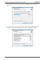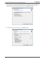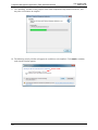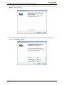
1
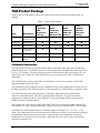
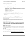
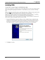
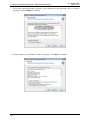
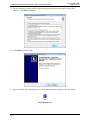
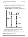
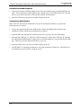
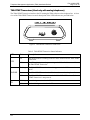
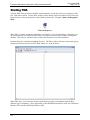
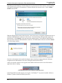
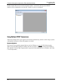
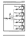
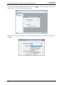
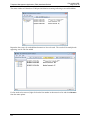
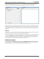
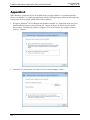
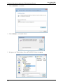
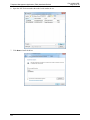
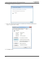
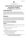
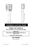
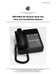
Pub. 42004-478E GAI-TRONICS® CORPORATION A HUBBELL COMPANY Telephone Management Application (TMA) Installation Bulletin Confidentiality Notice This manual is provided solely as an operational, installation, and maintenance guide and contains sensitive business and technical information that is confidential and proprietary to GAI-Tronics. GAI-Tronics retains all intellectual property and other rights in or to the information contained herein, and such information may only be used in connection with the operation of your GAI-Tronics product or system. This manual may not be disclosed in any form, in whole or in part, directly or indirectly, to any third party. This manual covers TMA version 7.6.0 and newer. Introduction The GAI-Tronics Telephone Management Application (TMA) is used to monitor the activity and health of GAI-Tronics RED ALERT®, SMART Industrial, VoIP/WiFi, and GSM Cellular Telephones. The reports and information provided by TMA can prove useful in reducing maintenance labor costs and greatly reduce liabilities typically associated with an emergency communication system. TMA runs continuously on a dedicated personal computer and it uses a GSM cellular modem, an Ethernet connection and one or more voice-mode modems or DTMF transceivers to gather status information from each telephone at regular intervals. In addition, the System Manager uses TMA to remotely adjust the behavior of individual telephones. These adjustments are either sent to the telephone immediately or in the case of the analog telephones can be held to be sent during the next scheduled health-check maintenance call. TMA provides an at-a-glance view of the status of the telephones as well as customizable reporting in the form of scheduled printed reports, and reports generated on demand. For questions about TMA, please contact: Service Group GAI-Tronics Corporation 400 E. Wyomissing Avenue Mohnton, PA 19540 800-492-1212 (8 a.m. to 5 p.m. EST) 610-777-1374 outside the USA GAI-Tronics Corporation 400 E. Wyomissing Ave. Mohnton, PA 19540 USA 610-777-1374 800-492-1212 Fax: 610-796-5954 VISIT WWW.GAI-TRONICS.COM FOR PRODUCT LITERATURE AND MANUALS Pub. 42004-478E Page 2 of 24 Telephone Management Application (TMA) Installation Bulletin TMA Product Package Upon receipt of a TMA product, inspect the contents of the carton to ensure the following items are included: Table 1. TMA Product Packages Item Description Model 12509-042 TMA Application Package Model 12509-043 TMA Line Expansion Kit 44008-004 TMA DTMF Transceiver Unit 44306-7xx USB Flash Drive 49186-008 Security Key 61007-007 Cable Assembly, 4-conductor 61007-044 USB Cable 44012-001 GSM Cellular Modem Model 12509-044 TMA VoIP Only Kit Model 12509-047 GSM TMA Application Package Component Descriptions The TMA DTMF Transceiver is used to interface the PC running the TMA application and dedicated PABX telephone line. The DTMF Transceiver is a black plastic box with sloped sides measuring 5.50 L 5.25 W 1.75 D inches. The front of the unit has three LEDs and the rear has one USB type “B” jack, and one RJ11 jack. NOTE: The TMA DTMF Transceiver is not required for VoIP or GSM cellular applications. The USB Flash Drive contains all the files to be installed on a PC that are required to run the TMA application and the TMA User Guide. The USB Security Key provides the necessary hardware security for the Administrator account access to the TMA application. The USB Security Key has the appearance of a USB flash drive (or memory stick). The USB cables are used to interconnect the PC running the TMA application with the DTMF Transceiver and GSM modem. The cable is equipped with a USB type “A” plug at one end for connection to a USB port at the PC, and a USB type “B” plug at the other end for connection to the DTMF Transceiver and GSM modem. The telephone line cord is used to connect the DTMF Transceiver to a dedicated PABX telephone line. The telephone line cord is equipped with an RJ11 plug at each end and is approximately 7 feet in length. The MultiTech® GSM cellular modem is an aluminum chassis measuring 3.17 L 2.45 W 1.16 D inches. The modem has LEDs to indicate status of the GSM wireless signal. A local antenna is included, but depending on the location of the installation a remote antenna (not included) may be required. NOTE: Before you can begin to use the modem, a SIM card from your wireless carrier will need to be installed for network access. f:\standard ioms - current release\42004 instr. manuals\42004-478e.docx 08/15 Telephone Management Application (TMA) Installation Bulletin Pub. 42004-478E Page 3 of 24 System Requirements The minimum system requirements for installing and running the TMA are: The GAI-Tronics TMA software System Manager (Host) PC equipped with the following: - Intel® or AMD® 32-bit or 64-bit Processor Microsoft® Windows® 7 SP1 or Windows® 8.1 operating system RAM, hard disk space, and processor speed is dependent on the operating system's recommended requirements One USB port for the security key One USB port per TMA DTMF Transceiver One USB port for the GSM modem One printer port One Ethernet connection to a Local Area Network (For VoIP telephones only) One telephone line connection (PBX/PABX only*) per TMA DTMF Transceiver (for analog telephones only) SIM card from a wireless service to install in the GSM modem (For GSM telephones only) *The No. 44008-004 DTMF Transceiver is not an FCC approved device. This prohibits connection to the “public network” without first being routed through a PBX/PABX telephone switch. The host PC should be installed in a controlled environment such an office without extremes in temperature, humidity or dust. The “System Manager” must be Microsoft Windows® literate and knowledgeable of the use of a computer, copying files, renaming files, etc. Microsoft® is a registered trademark of Microsoft Corporation. Windows® 7 and Windows® 8.1 are trademarks of Microsoft Corporation. Windows® 7 users: SP1 or above is required. Refer also to the Readme.txt file on the installation USB Flash Drive. To confirm the Service Pack is installed, right click on the desktop icon Computer, and select Properties. Examine the Windows edition section, and confirm the Service Pack is listed. Windows® Considerations The TMA application is intended to run on a PC dedicated to the Telephone Management Application. Running other applications while TMA is active may affect the operation of TMA. To make optimum use of the Windows® taskbar while TMA is running Full Screen, activate the Windows® taskbar “Auto Hide” option. NOTE 1: Having the Windows® taskbar at the top or bottom of the screen and set to ‘Always on top,’ and without the ‘Auto Hide’ option being active may block a portion of the TMA display. NOTE 2: TMA is intended for use with the Windows® Regional setting set as either English (United States), or English (United Kingdom). Avoid using a 12-hour date format without an AM/PM setting. f:\standard ioms - current release\42004 instr. manuals\42004-478e.docx 08/15 Telephone Management Application (TMA) Installation Bulletin Pub. 42004-478E Page 4 of 24 Installing TMA To install TMA, you must be logged on with administrator rights. TMA and its components are contained on the provided USB Flash Drive. Please exit all other programs that are running before beginning the installation. To install TMA to your PC, perform the following steps: NOTE 1: Do not insert the USB security key until instructed to do so. If TMA is already installed on the PC, uninstall the existing TMA application prior to starting this TMA installation. NOTE 2: The installation examples shown on the following pages represent a Windows® 7 installation, and may differ slightly in appearance to an installation on a PC running Windows® 8.1. NOTE 3: MultiTech® serial port modems (Models MT5656ZDXV and MT5600ZDXV) employed with older versions of TMA are compatible with this version of TMA. 1. Place the USB Flash Drive into the PCs USB port. If the “AutoRun” feature is enabled, the main installation screen should appear in approximately 20 seconds. If the installation does not start up automatically, use Windows® Explorer to open the USB Flash Drive folder and double-click the Tma_Setup.exe filename. When the installation begins, the following screen should appear: 2. Click Next > to continue. f:\standard ioms - current release\42004 instr. manuals\42004-478e.docx 08/15 Telephone Management Application (TMA) Installation Bulletin Pub. 42004-478E Page 5 of 24 3. The License Agreement window will appear. After reading the license agreement, select “I accept the agreement” and click Next > to continue. 4. Upon acceptance, an “Information” window will appear. Click Next > to continue. f:\standard ioms - current release\42004 instr. manuals\42004-478e.docx 08/15 Telephone Management Application (TMA) Installation Bulletin Pub. 42004-478E Page 6 of 24 5. The “Select Destination Location” window will appear. Click Next > to accept the default folder location. 6. The next window asks “Which components should be installed?” A typical installation requires all components to be installed. Ensure all check boxes are checked and click Next > to continue. f:\standard ioms - current release\42004 instr. manuals\42004-478e.docx 08/15 Telephone Management Application (TMA) Installation Bulletin Pub. 42004-478E Page 7 of 24 7. The next window asks to select which GSM modem drivers to be installed. Unselect the modem type that will not be used. Unselect both if there will be no GAI-Tronics GSM phones to be polled. Let both selected if it is unknown which modem is to be used. Click Next > to continue. 8. An installation summary is then presented. Click Install to continue. f:\standard ioms - current release\42004 instr. manuals\42004-478e.docx 08/15 Telephone Management Application (TMA) Installation Bulletin Pub. 42004-478E Page 8 of 24 9. The “Installing” window reveals progress of the TMA components being installed on the PC, and may take a few minutes to complete. 10. The following security window will appear for each driver to be installed. Click Install to continue, each time the window appears. Driver Name f:\standard ioms - current release\42004 instr. manuals\42004-478e.docx 08/15 Telephone Management Application (TMA) Installation Bulletin Pub. 42004-478E Page 9 of 24 11. If the MultiTech® GSM modem was selected for installing the drivers this window will appear. Click Next > to install the drivers. 12. Once the MultiTech® GSM modem driver installation is completed the following window will appear. Click Finish to continue. f:\standard ioms - current release\42004 instr. manuals\42004-478e.docx 08/15 Telephone Management Application (TMA) Installation Bulletin Pub. 42004-478E Page 10 of 24 13. The next window to appear provides information about this and previous release versions of the software. Click Next > to continue. 14. Click Finish to exit the setup. 15. Upon conclusion of the installation process, the following icon should appear on the PC desktop. TMA Desktop Icon f:\standard ioms - current release\42004 instr. manuals\42004-478e.docx 08/15 Telephone Management Application (TMA) Installation Bulletin Pub. 42004-478E Page 11 of 24 Device Connections Connections for Analog Telephones 1. With the TMA software installation complete, the TMA DTMF Transceiver must be connected to the PC and PBX/PABX extension telephone line using the USB cable and telephone line cords provided. Refer to Figure 1 below and the following guidelines for these connections: USB connection – Insert the large USB type “A” plug into a USB port at the PC, and the small USB type “B” plug into the USB jack at the rear of the TMA DTMF Transceiver. PABX telephone connection – Insert one end of the telephone line cord into the RJ11 jack at the rear of the TMA DTMF Transceiver, and the other end into a dedicated PABX jack at the wall. Figure 1. TMA DTMF Transceiver Connections 2. After the USB and telephone cables are connected, the TMA DTMF Transceiver OH/PWR LED should begin to flash on and off to indicate the unit is receiving power via the USB connection. 3. Insert the USB security key into an available USB port at the PC. 4. Upon Windows® recognizing the hardware it will begin installation of the drivers. After the drivers are installed you may be asked to restart the system. NOTE : If using MultiTech® serial port modems (Models MT5656ZDXV and MT5600ZDXV) see Appendix A about ensuring the correct drivers are installed. f:\standard ioms - current release\42004 instr. manuals\42004-478e.docx 08/15 Telephone Management Application (TMA) Installation Bulletin Pub. 42004-478E Page 12 of 24 Connections for VoIP/WiFi Telephones 1. Connect the computer’s Ethernet adapter to the Local Area Network using a standard RJ45 Ethernet cable. This is required for VoIP telephones only. NOTE: Port 23 (TCP/UDP) and port 514 (Syslog) must be open on the network for communication with the VoIP telephones. 2. Insert the USB security key into an available USB port at the PC. Connections for GSM Telephones Refer to the user manual of the GSM modem for specific installation information. In general the following steps are required. 1. Connect the supplied antenna to the GSM modem. NOTE: Depending on the location of the installation a remote antenna (not included) may be required. 2. Install the SIM card acquired from a GSM wireless service provider into the GSM modem. 3. Insert the large USB type “A” plug into a USB port at the PC, and the small USB type “B” plug into the USB jack at the GSM modem. Apply power to the GSM modem if it is not powered by the USB port. The Power LED will light after the device powers up. 4. Insert the USB security key into an available USB port at the PC. 5. Upon Windows® recognizing the hardware it will begin installation of the drivers. After the drivers are installed you may be asked to restart the system. f:\standard ioms - current release\42004 instr. manuals\42004-478e.docx 08/15 Telephone Management Application (TMA) Installation Bulletin Pub. 42004-478E Page 13 of 24 TMA DTMF Transceiver (Used only with analog telephones) The TMA DTMF Transceiver interfaces the PC running the TMA software to the telephone line. A front view of the TMA DTMF Transceiver and a description of the LED indicators are provided below: Figure 2. TMA DTMF Transceiver Front View Table 2. TMA DTMF Transceiver Status Indicators LED Status Description On The SPI application is running on the PC and is connected to the TMA DTMF Transceiver. Off The SPI application is no longer running on the PC and is disconnected from the TMA DTMF Transceiver. Flashing The TMA DTMF Transceiver is receiving power via the USB connection to the PC. On The TMA DTMF Transceiver is off-hook and connected to the phone line. Off The TMA DTMF Transceiver is on-hook. If the DTR LED is also off, the DTMF Transceiver is not powered. Blinking Data is being transmitted to the PC. Off No data is being transmitted to the PC. DTR OH/PWR TD f:\standard ioms - current release\42004 instr. manuals\42004-478e.docx 08/15 Telephone Management Application (TMA) Installation Bulletin Pub. 42004-478E Page 14 of 24 Starting TMA After the TMA software has been installed, and the hardware security key has been inserted into a USB port, TMA can be started. To start TMA, double click the desktop TMA icon with the GAI-Tronics logo (shown below) or start the application via the Windows Start menu. The path is Start > All Programs > TMA. TMA Desktop Icon When TMA is initially started after installation, it will display a “No Current Database” dialog box over the startup splash screen, which indicates TMA was not able to open the most recently used telephone database. This is due to a database name not being defined for this new TMA installation. Read the dialog box, and then select OK to dismiss it. The TMA window will now contain empty panels, and pull-down menu selections for FILE, EDIT, VIEW , etc., as shown below. When TMA starts, it also starts the interface applications necessary to communicate with the three different types of telephones. These applications are the SMART Phone Interface (SPI), the VoIP Phone Interface (VPI) and the GSM Phone Interface (GPI). f:\standard ioms - current release\42004 instr. manuals\42004-478e.docx 08/15 Telephone Management Application (TMA) Installation Bulletin Pub. 42004-478E Page 15 of 24 Depending upon the Windows® firewall settings, the very first time the VPI is started; a security window may appear informing the VPI component is currently blocked from network access. Select to Allow access to the network. When the GPI application starts for the first time, it may be necessary to assign the communication port to which the GSM modem has connected. If this occurs, a connection setup warning window appears (as shown below). Select Cancel to reach the connection settings window. Select from the drop-down list the port name to which the GSM modem has connected. If a GSM modem will not be used click Cancel to exit the settings window. Once these selections have been made the settings window should not reappear unless the COM port assignment to the GSM modem is lost due to it being disconnected from the PC. After a few seconds, confirm an icon appears in the taskbar notification area for each of the interface applications that are running. GPI, SPI and VPI Icons in Taskbar Notification Area If the VPI and GPI icons fail to appear, service pack 1 for Windows® 7 may not be installed. Perform a Windows® update to install the needed system files. f:\standard ioms - current release\42004 instr. manuals\42004-478e.docx 08/15 Telephone Management Application (TMA) Installation Bulletin Pub. 42004-478E Page 16 of 24 Double-click the SPI icon to reveal the call status window. On the left is the list pane of DTMF transceiver lines configured to use by the SPI. Initially, no lines are configured. Using Multiple DTMF Transceivers TMA allows multiple lines (up to eight) to be monitored simultaneously, which is useful in larger systems with hundreds of phones or when daily updates are needed. Equipment Required Since most PCs are typically equipped with two to four USB ports, a powered USB 2.0 hub must be added. Powered USB 2.0 hubs are available with four to ten ports. In addition to the powered USB 2.0 hub, a Model 12509-043 TMA Expansion Kit is required for each additional line to be added. (See Table 1 for kit components.) f:\standard ioms - current release\42004 instr. manuals\42004-478e.docx 08/15 Telephone Management Application (TMA) Installation Bulletin Pub. 42004-478E Page 17 of 24 Refer to Figure 3 for typical interconnection of a system utilizing four lines to monitor the telephones. Figure 3 below is a diagram showing connections for a four-line monitoring system. Figure 3. Typical Four-Line Monitoring Detail f:\standard ioms - current release\42004 instr. manuals\42004-478e.docx 08/15 Telephone Management Application (TMA) Installation Bulletin To add a line, select File, then New from the menu or click the status window. A Transceiver Select window appears. Pub. 42004-478E Page 18 of 24 icon above the list pane of the SPI call Choose from the drop-down list in the Transceiver Select field the transceiver to connect to the line and click OK. f:\standard ioms - current release\42004 instr. manuals\42004-478e.docx 08/15 Telephone Management Application (TMA) Installation Bulletin Pub. 42004-478E Page 19 of 24 The status window will then show COM port initialization occurring indicating a successful addition. Repeat the above steps for each additional transceiver line to be used. The result will be multiple tabs appearing, one for each line added. If a line needs to be removed, right-click on the line number in the transceiver list and select Remove from the menu options. f:\standard ioms - current release\42004 instr. manuals\42004-478e.docx 08/15 Telephone Management Application (TMA) Installation Bulletin Pub. 42004-478E Page 20 of 24 Double-clicking the GPI and the VPI icons will reveal the call status window for each application as shown below. In the GPI call status window a signal strength meter appears in the top right. The call status windows of the three interface applications allow the progress of a maintenance call with a SMART phone, VoIP phone and GSM phone to be viewed. Please note that the status windows may be visible, or hidden; in either case, they will run normally, processing calls at the request of the main TMA application. Helpful Tips It may be more convenient to have the main TMA application running in a window (not full screen), and simultaneously have the status windows visible on the Windows® desktop. To prevent any of the interface applications from running when TMA is started, go to the Communication tab in the TMA Options window found in the Tools menu. For telephone types not being monitored, unselect the start-up application for those telephone types. When TMA is restarted, the application will not be started and its icon will not appear in the Taskbar Notification Area. Installation Completed To begin using TMA, select Help from the TMA menu, then TMA Help to display the online manual. Go to the “Starting TMA” section of the manual for further instructions for creating and building the TMA database, and how to use TMA to maintain the GAI-Tronics telephones on site. f:\standard ioms - current release\42004 instr. manuals\42004-478e.docx 08/15 Telephone Management Application (TMA) Installation Bulletin Pub. 42004-478E Page 21 of 24 Appendix A When Windows® installs the drivers for the MultiTech® serial port modems it is possible that default drivers were installed. To ensure proper operation with the TMA application perform the following steps to choose the drivers provided with the TMA software package. 1. Navigate to Windows® Device Manager and expand the modems list. Right-click on the serial port modem and select Properties from the menu list. Choose the Driver tab and click on the Update Driver button. The following window will appear. Click on the ‘Browse my computer for driver software’ selection. 2. Choose the ‘Let me pick from a list of device drivers on my computer’ option. f:\standard ioms - current release\42004 instr. manuals\42004-478e.docx 08/15 Telephone Management Application (TMA) Installation Bulletin 3. Choose Have Disk… to continue. 4. Choose Browse… to locate the drivers. 5. Navigate to the TMA_Modem_Driver_MT5656ZDXV folder for Look in. f:\standard ioms - current release\42004 instr. manuals\42004-478e.docx 08/15 Pub. 42004-478E Page 22 of 24 Telephone Management Application (TMA) Installation Bulletin 6. Open the .INF file that matches the model serial modem in use. 7. Click Next to install the driver. f:\standard ioms - current release\42004 instr. manuals\42004-478e.docx 08/15 Pub. 42004-478E Page 23 of 24 Telephone Management Application (TMA) Installation Bulletin Pub. 42004-478E Page 24 of 24 8. Click Close to finish the driver installation. 9. Return to the modem Properties window to view the Driver tab. The driver installed should be version 7.5.4.9 with a date of 5/4/2009. 10. Click Close to finish. f:\standard ioms - current release\42004 instr. manuals\42004-478e.docx 08/15 Warranty Equipment. GAI-Tronics warrants for a period of one (1) year from the date of shipment, that any GAI-Tronics equipment supplied hereunder shall be free of defects in material and workmanship, shall comply with the then-current product specifications and product literature, and if applicable, shall be fit for the purpose specified in the agreed upon quotation or proposal document. If (a) Seller’s goods prove to be defective in workmanship and/or material under normal and proper usage, or unfit for the purpose specified and agreed upon, and (b) Buyer’s claim is made within the warranty period set forth above, Buyer may return such goods to GAI-Tronics nearest depot repair facility, freight prepaid, at which time they will be repaired or replaced, at Seller’s option, without charge to Buyer. Repair or replacement shall be Buyer’s sole and exclusive remedy. The warranty period on any repaired or replacement equipment shall be the greater of the ninety (90) day repair warranty or one (1) year from the date the original equipment was shipped. In no event shall GAI-Tronics warranty obligations with respect to equipment exceed 100% of the total cost of the equipment supplied hereunder. Buyer may also be entitled to the manufacturer’s warranty on any third-party goods supplied by GAI-Tronics hereunder. The applicability of any such third-party warranty will be determined by GAI-Tronics. Services. Any services GAI-Tronics provides hereunder, whether directly or through subcontractors, shall be performed in accordance with the standard of care with which such services are normally provided in the industry. If the services fail to meet the applicable industry standard, GAI-Tronics will reperform such services at no cost to buyer to correct said deficiency to Company's satisfaction provided any and all issues are identified prior to the demobilization of the Contractor's personnel from the work site. Re-performance of services shall be Buyer's sole and exclusive remedy, and in no event shall GAITronics warranty obligations with respect to services exceed 100% of the total cost of the services provided hereunder. Warranty Periods. Every claim by Buyer alleging a defect in the goods and/or services provided hereunder shall be deemed waived unless such claim is made in writing within the applicable warranty periods as set forth above. Provided, however, that if the defect complained of is latent and not discoverable within the above warranty periods, every claim arising on account of such latent defect shall be deemed waived unless it is made in writing within a reasonable time after such latent defect is or should have been discovered by Buyer. Limitations / Exclusions. The warranties herein shall not apply to, and GAI-Tronics shall not be responsible for, any damage to the goods or failure of the services supplied hereunder, to the extent caused by Buyer’s neglect, failure to follow operational and maintenance procedures provided with the equipment, or the use of technicians not specifically authorized by GAI-Tronics to maintain or service the equipment. THE WARRANTIES AND REMEDIES CONTAINED HEREIN ARE IN LIEU OF AND EXCLUDE ALL OTHER WARRANTIES AND REMEDIES, WHETHER EXPRESS OR IMPLIED BY OPERATION OF LAW OR OTHERWISE, INCLUDING ANY WARRANTIES OF MERCHANTABILITY OR FITNESS FOR A PARTICULAR PURPOSE. Return Policy If the equipment requires service, contact your Regional Service Center for a return authorization number (RA#). Equipment should be shipped prepaid to GAI-Tronics with a return authorization number and a purchase order number. If the equipment is under warranty, repairs or a replacement will be made in accordance with the warranty policy set forth above. Please include a written explanation of all defects to assist our technicians in their troubleshooting efforts. Call 800-492-1212 (inside the USA) or 610-777-1374 (outside the USA) for help identifying the Regional Service Center closest to you. (Rev. 10/06)