1
AT Commands,
Voice Commands
S-Registers, and Result Codes
MT5656ZDX Series
MT5600ZDX Series
MT5600BA/BL Series
Reference Guide
Copyright
AT Commands, S-Registers, and Result Codes
Reference Guide
MT5656ZDX, MT5656ZDX–V, MT5600ZDX, MT5600ZDX–V, MT5600BA–V.92, MT5600BA–V.90, MT5600BL–V.90
P/N S000273D Revision D
©2003-4 by Multi-Tech Systems, Inc.
All rights reserved. This publication may not be reproduced, in whole or in part, without prior expressed written
permission from Multi-Tech Systems, Inc.
Multi-Tech Systems, Inc. makes no representations or warranties with respect to the contents hereof and
specifically disclaims any implied warranties of merchantability or fitness for any particular purpose.
Furthermore, Multi-Tech Systems, Inc. reserves the right to revise this publication and to make changes in the
content hereof without obligation of Multi-Tech Systems, Inc. to notify any person or organization of such revisions
or changes.
Record of Revisions
Revision
Date
Description
A
10/04/02
Initial release.
B
02/20/03
Changed the V.92 Distinctive Ring Control to +VDR. Edited the Escape Sequence text.
Added +VRID to Caller ID. Edited the +FCLASS= command. Added MT5600BA/BL–V.90
commands.
C
10/09/03
Added Voice Commands. Enhanced the descriptions of the following commands:
escape, initiate remote configuration, +FCLASS. Removed #CBA and #CBD, which are
not supported. Add MT5600ZDX to cover.
D
12/13/04
Add note to synchronous clock that Synchronous Online (&M1) must be enabled before
you can set the synchronous clock. Updated voice commands. Add V.25bis commands.
Trademarks
MultiModem, MultiModemII, Multi-Tech, and the Multi-Tech logo are trademarks of Multi-Tech Systems, Inc.
World Headquarters
Multi-Tech Systems, Inc.
2205 Woodale Drive
Mounds View, MN 55112
U.S.A
Telephone (763) 785-3500 or (800) 328-9717
Fax (763) 785-9874
Technical Support (800) 972-2439
Internet http://www.multitech.com
Multi-Tech Systems, Inc. Commands Reference Guide (PN S000273D)
2
Table of Contents
Contents
AT Commands Introduction .................................................................................................................. 4
AT Commands Detail ........................................................................................................................... 5
Escape Commands ........................................................................................................................... 18
V.92 Commands ................................................................................................................................ 18
Caller ID Commands (V.92) ............................................................................................................... 20
Callback Security Commands (V.92) ................................................................................................. 21
Other V.92 Commands ...................................................................................................................... 22
V.8/V.8bis Commands ........................................................................................................................ 32
MT5600BA/BL–V.90 Commands........................................................................................................ 33
Voice Commands ............................................................................................................................... 36
Voice Commands Overview ........................................................................................................ 36
Configuration Commands ........................................................................................................... 37
Speakerphone Commands ......................................................................................................... 42
Unsolicited Voice Mode Result Codes ......................................................................................... 43
Unformatted Form Reporting ....................................................................................................... 44
Voice Mode Shielded Codes ........................................................................................................ 44
Voice Sample Sessions .............................................................................................................. 46
Answer Phone, Play Greeting Message, and Record Message Example .................................. 47
V.25 bis Commands ........................................................................................................................... 48
V.25 bis Responses .................................................................................................................... 49
V.92 S-Registers ................................................................................................................................ 50
V.90 S-Registers ................................................................................................................................ 52
Result Codes ..................................................................................................................................... 53
Multi-Tech Systems, Inc. Commands Reference Guide (PN S000273D)
3
AT Commands for the MT5656ZDX, MT5600ZDX, MT5600BA/BL-Series Modems
AT Commands Introduction
AT commands are used to control the operation of your modem. They are so called because each command must be
preceded by the characters AT to get the ATtention of the modem.
AT commands can be issued only when the modem is in command mode or online command mode.
•
•
The modem is in command mode whenever it is not connected to another modem.
The modem is in data mode whenever it is connected to another modem and ready to exchange data. Online
command mode is a temporary state in which you can issue commands to the modem while connected to
another modem.
To put the modem into online command mode from data mode, you must issue an escape sequence: Type +++ and
wait for the OK response; then issue the hang-up command by typing ATH <CR> (<CR> indicates that you must click
Enter). To return to data mode from online command mode, type the command ATO.
To send AT commands to the modem you must use a communications program, such as the Phone Tools, a
communications program included with your modem, or HyperTerminal in Windows 95, 98, NT 4.0, Me, 2000, XP. You
can issue commands to the modem either directly, by typing them in the terminal window of the communications
program, or indirectly, by configuring the operating system or communications program to send the commands
automatically. Fortunately, communications programs make daily operation of modems effortless by hiding the
commands from the user. Most users, therefore, need to use AT commands only when reconfiguring the modem,
e.g., to turn autoanswer on or off.
The format for entering an AT command is ATXn, where X is the command and n is the value for the command,
sometimes called the command parameter. The value is always a number. If the value is zero, you can omit it from
the command; thus, AT&W is equivalent to AT&W0. Most commands have a default value, which is the value that is
set at the factory. The default values are shown in the “AT Commands” section, which begins on the next page.
You must press Enter to send the command to the modem.
Any time the modem receives a command, it sends a response known as a result code. The most common result
codes are OK, ERROR, and the CONNECT messages that the modem sends to the computer when it is connecting
to another modem. For a table of valid result codes, see the “Result Codes” sections of this manual.
You can issue several commands in one line, in what is called a command string.
The command string begins with AT and ends when you press ENTER. Spaces to separate the commands are
optional; they are ignored by the command interpreter. The most familiar command string is the initialization string,
which is used to configure the modem when it is turned on or reset, or when your communications software calls
another modem.
Note about the LED graphics.
The graphics are labeled MT5600BA. This stands for the MT5600BA-Series and includes the MT5600BA and the
MT5600BL.
Multi-Tech Systems, Inc. Commands Reference Guide (PN S000273D)
4
AT Commands for the MT5656ZDX, MT5600ZDX, MT5600BA/BL-Series Modems
AT Commands Detail
Command:
AT
Values:
Description:
Attention Code
n/a
The attention code precedes all command lines except A/ and the escape sequence.
Command:
Enter Key
Values:
Description:
n/a
Press the ENTER or RETURN key to execute most commands.
Command:
A
Values:
Description:
Answer
n/a
Answers an incoming call before the final ring.
MT5600BA LCD:
Command:
A/
Values:
Description:
Command:
Bn
Values:
Default:
Description:
Command:
Values:
Default:
Description:
Repeat Last Command
n/a
Repeats the last command string. Do not precede this command with AT. Do not press
ENTER to execute.
Communication Standard Setting
n = 0 or 1
1
B0 Selects ITU-T V.22 mode when the modem is at 300 or 1200 bps.
B1 Selects Bell 212A when the modem is at 300 or 1200 bps.
Ds
Dial
s = dial string (phone number and dial modifiers)
none
Dials telephone number s, where s may be up to 40 characters long and include the
following dial string modifiers.
MT5600BA LCD:
0–9
*
#
A–D
L
P
T
W
,
;
!
@
^
&
Digits 0 through 9
The “star” digit (tone dialing only)
The “pound” digit (tone dialing only)
A, B, C, and D tone digits. Country specific; some countries may prohibit these digits.
Redial last number. (Must be placed immediately after ATD.)
Select pulse-dialing until a T is encountered. Affects current and subsequent dialing.
Select tone-dialing until a P is encountered. Affects current and subsequent dialing.
Wait for a new dial tone before continuing to dial. (X2 or X4 must be selected.)
Pause during dialing for time set in register S8.
Return to command mode after dialing. (Place at end of dial string.)
Hook flash. Causes the modem to go quicking on-hook then back off-hook.
Wait for silence. Causes the modem to wait for 5 seconds of silence before
processing the next part of the command. If silence is not detected within the time set
in register S7, the modem returns a NO ANSWER or BUSY code.
Toggle data calling tone on or off. Applies only to current dialing attempt.
Detect credit card “bong” tone. If the tone is not detected within the time specified by
S7 (US models), the modem aborts the rest of the sequence and hangs up. The
character should follow the phone number and precede the user’s call card number,
e.g., ATDT1028806127853500&123456789.
Multi-Tech Systems, Inc. Commands Reference Guide (PN S000273D)
5
AT Commands for the MT5656ZDX, MT5600ZDX, MT5600BA/BL-Series Modems
Command:
DS=n
Values:
Default:
Description:
Dial Stored Telephone Number
n = 0–3
none
Dial a number previously stored in directory number n by the &Zn=x command.
Example: ATDS=3.
MT5600BA LCD:
Command: En
Echo Command Mode Characters
Values:
Default:
Description:
n = 0 or 1
1
E0
Do not echo keyboard input to the terminal.
E1
Do echo keyboard input to the terminal.
Command:
Hn
Values:
Default:
Description:
Hook Control
n = 0 or 1
0
H0
Go on-hook (hang up) and terminate any &T test in progress.
H1
Go off-hook (make the phone line busy); enters command mode.
MT5600BA LCD:
Command:
In
Values:
Default:
Description:
Information Request
n = 0–6
None
I0
Display the product code. Example: MT5600BA-V92.
I1
Calculate the ROM checksum and display the least significant byte in decimal format.
I2
Calculate the ROM checksum and compare it to the prestored checksum, displaying
OK if they match, or ERROR if they do not.
I3
Display the firmware version and application codes.
I4
Display the OEM-defined identifier string in either binary or ASCII format.
I5
Display the country code. Example: 098.
I6
Display the modem data pump model and internal code version.
Command:
L
Command:
L5
Value:
Default:
Description:
Not applicable.
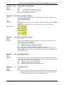
Lists Current Operating Parameters (MT5600BA/BL only)
5
None
Displays the current values for the error correction, flow control, data compression, and
serial port speed commands. Example:
atL5
&E2 &E3 &E15 $SB115200
OK
Note: Use the &V command to display the other parameters.
Command:
Values:
Default:
Description:
Mn
Monitor Speaker Mode
n = 0, 1, 2, or 3
1
M0
Speaker
M1
Speaker
M2
Speaker
M3
Speaker
is
is
is
is
always off.
on until the carrier signal is detected.
always on when the modem is off-hook.
off when receiving carrier and during dialing, but on during answering.
Multi-Tech Systems, Inc. Commands Reference Guide (PN S000273D)
6
AT Commands for the MT5656ZDX, MT5600ZDX, MT5600BA/BL-Series Modems
Command:
On
Values:
Default:
Description:
Return Online to Data Mode
0 or 1
None
O0
O1
Command:
P
Values:
Default:
Description:
Exit online command mode and return to online data mode without a retrain.
Normally used after a +++ escape (see +++ escape sequence).
Exit online command mode and return to online data mode after a retrain.
Pulse Dialing
P, T
T
Forces pulse (non-touch-tone) dialing until a T command or T dial modifier is received.
MT5600BA LCD:
Command:
Qn
Values:
Default:
Description:
Result Codes Enable/Disable
n = 0 or 1
0
Q0
Q1
Enable result codes.
Disable result codes
MT5600BA LCD:
Command:
Sr
Values:
Default:
Description:
Select Register
r = S-register number
None
Selects register Sr as the last register accessed. E.g., S0. The command AT? can then be
used to read the register, and the command AT=n can then be used to set the register to
value n.
Command:
Sr=n Set Register Value
Values:
Default:
Description:
r = S-register number; n varies
None
Sets value of register Sr to n, where n is entered in decimal format. E.g., S0=1. If the
short form AT=n is used, the value is written to the last accessed S-register.
MT5600BA LCD:
Command:
Sr?
Values:
Default:
Description:
Read Register Value
r = S-register number
None
Reads value of register Sr and display it in 3-digit decimal format. E.g., S2? gives the
response 043. If the short form AT? is used, the last accessed S-register is read.
MT5600BA LCD:
Command:
T
Values:
Default:
Description:
Tone Dialing
P, T
T
Forces DTMF (touch-tone) dialing until a P command or P dial modifier is received.
MT5600BA LCD:
Multi-Tech Systems, Inc. Commands Reference Guide (PN S000273D)
7
AT Commands for the MT5656ZDX, MT5600ZDX, MT5600BA/BL-Series Modems
Command:
Vn
Values:
Default:
Description:
Result Code Format
n = 0 or 1
1
V0
Displays result codes as digits (terse response).
V1
Displays result codes as words (verbose response)
MT5600BA LCD:
Command:
Wn
Values:
Default:
Description:
Command:
Connect Message Control
n = 0, 1, or 2
0
W0
The CONNECT result code reports the serial port speed only.
W1
The CONNECT result code reports the line speed, the error correction protocol,
and the serial port speed, respectively.
W2
The CONNECT result code reports the line speed only.
Note: See also the \V command
Xn
Values:
Default:
Description:
Result Code Selection
n = 0–4
Country Dependent
This command selects which result message subset the modem will use to inform the
computer of the results of commands.
X0 Sends OK, CONNECT, RING, NO CARRIER, ERROR and NO ANSWER; does not
look for dial tone or busy signal.
MT5600BA LCD:
X1
X2
X3
X4
Sends
Sends
Sends
Sends
X0 messages and connect speed; doesn’t look for dial tone or busy signal.
X1 messages with NO DIALTONE; does not look for busy signal.
X1 messages with BUSY; does not look for dial tone.
all messages, including NO DIALTONE and BUSY.
5600BA LCD:
Note: In fax mode, the only message sent to indicate a connection is: CONNECT without a
speed indication. See also the \V command.
Command:
Yn
Values:
Default:
Description:
Command:
Values:
Default:
Description:
Long Space Disconnect
n = 0 or 1
0
Y0 Disables sending/responding to a long space break signal on disconnect.
Y1 Enables long space disconnect. In non-error correction mode, the modem sends a
long space of four seconds prior to going on-hook. In non-error correction mode, the
modem responds to the receipt of a long space (i.e., a break signal greater than 1.6
seconds) by going on-hook.
Zn
Modem Reset
n = 0 or 1
None
The modem performs a soft reset and restores (recalls) the configuration profile according
to the parameter supplied. If no parameter is specified, zero is assumed.
Z0 Resets modem and restores Profile 0.
Z1 Resets modem and restores Profile 1.
Note: See also the &F and &W commands.
Multi-Tech Systems, Inc. Commands Reference Guide (PN S000273D)
8
AT Commands for the MT5656ZDX, MT5600ZDX, MT5600BA/BL-Series Modems
Command:
&Cn
Values:
Default:
Description:
Data Carrier Detect (DCD) Control
n = 0 or 1 (all models) 0, 1, 2, 3, 4, 5, 6, 7 (MT5600BA only)
1, 3, 4
&C0 Turns off reset on loss of carrier (all models).
&C1 A second way to turn off reset on loss of carrier (all models).
&C2 DCD goes high 500ms after CONNECT message is generated.
&C3 DCD goes high when the CONNECT message is generated.
&C4 Disables &C5 and &C6 command.
&C5 UNIX only: Holds DCD low until proper callback security password is entered or
until a disconnect occurs. This prevents UNIX login prompt from being displayed
before the callback security ENTER PASSWORD prompt appears (MT5600BA only).
&C6 Linux only: Wait to display the connect message until the proper callback security
password is entered.
&C7 Reset on loss of DCD.
MT5600BA LCD:
Command:
&Dn
Values:
Default:
Description:
Data Terminal Ready (DTR) Control
n = 0, 1, 2, or 3
2
This command interprets the high to low transition of the DTR signal sent by the computer
according to the supplied parameter. The action taken depends on the current &Q setting.
&D0
&Q0, &Q5, &Q6: DTR is ignored (assumed high). Allows operation with computers
that do not provide DTR.
&Q1: DTR drop causes the modem to hang up. Autoanswer is not affected.
&Q2, &Q3: DTR drop causes the modem to hang up. Autoanswer is inhibited.
&D1
&Q0, &Q1, &Q5, &Q6: DTR drop is interpreted by the modem as if the
asynchronous escape sequence had been entered. The modem returns to
asynchronous command state without disconnecting.
&Q2, &Q3: DTR drop causes the modem to hang up. Autoanswer is inhibited.
&D2
&Q0–&Q6: DTR drop causes the modem to hang up. Autoanswer is inhibited.
&D3
&Q0, &Q1, &Q5, &Q6: DTR drop causes modem to perform a soft reset as if the Z
command were received. The &Y setting determines which profile is loaded.
&Q2, &Q3: DTR drop causes the modem to hang up. Autoanswer is inhibited.
&Q5 or &Q6 and +FCLASS=1 or +FCLASS=2: Same as for &Q0.
Note: If &D1, &D2, or &D3 is set, the modem will not dial without a DTR drop.
MT5600BA LCD:
Command:
Values:
Default:
Description:
&En
V.42 Error Correction Modes (MT5600BA V.92 only)
n = 0, 1, or 2
1
&E0
V.42 non-error correction mode (V.42 disabled).
&E1
V.42 auto-reliable mode.
&E2
V.42 reliable mode (V.42 enabled).
MT5600BA LCD:
Multi-Tech Systems, Inc. Commands Reference Guide (PN S000273D)
9
AT Commands for the MT5656ZDX, MT5600ZDX, MT5600BA/BL-Series Modems
Command:
&En
Values:
Default:
Description:
Modem-Initiated Flow Control (MT5600BA V.92 only)
n = 3, 4, or 5
4
&E3
Flow control disabled.
&E4
CTS/RTS hardware flow control.
&E5
XON/XOFF software flow control.
MT5600BA LCD:
Note: See also the L5 and &K commands.
Command:
&En
Values:
Default:
Description:
Command:
&Fn
Values:
Default:
Description:
Command:
Values:
Defaults:
Description:
Load Factory Settings
n = 0 or 1
None
&F0 Load factory configuration 0.
&F1 Load factory configuration 1.
Note: See also the Z, L5, and &V commands.
&Gn
Values:
Default:
Description:
Command:
V.42bis Data Compression (MT5600BA V.92 only)
n = 14 or 15
15
&E14
V.42bis data compression disabled.
&E15
V.42bis data compression enabled.
Note: This command controls only V.42bis data compression, whereas the %C command
controls both V.42bis and MNP-5 data compression. The command in effect is the one last
entered. See also the L5 command.
V.22bis Guard Tone Control
n = 0, 1, or 2
Varies by country
&G0
Disables guard tone.
&G1
Sets guard tone to 550 Hz.
&G2
Sets guard tone to 1800 Hz.
Note: The &G command is not used in North America, and may not be permitted in some
countries.
&Kn
Flow Control Selection
n = 0, 3, 4, 5, or 6
3 (data modem mode)
6 (fax modem and voice modes)
&K0
Disables flow control.
&K3
Enables CTS/RTS hardware flow control.
&K4
Enables XON/XOFF software flow control.
&K5
Enables transparent XON/XOFF flow control.
&K6
Enables both CTS/RTS and XON/XOFF flow control.
Note: See also the &E command
Multi-Tech Systems, Inc. Commands Reference Guide (PN S000273D)
10
AT Commands for the MT5656ZDX, MT5600ZDX, MT5600BA/BL-Series Modems
Command:
&Mn
Values:
Default:
Description:
Command:
&Pn
Values:
Default:
Description:
Command:
Values:
Default:
Description:
Make/Break Dial Ratio
n = 0, 1, 2, 3
Varies by country
&P0 Make/Break
&P1 Make/Break
&P2 Make/Break
&P3 Make/Break
dial
dial
dial
dial
ratio
ratio
ratio
ratio
of
of
of
of
39/61
33/67
39/61
33/67
at
at
at
at
10
10
20
20
pps
pps
pps
pps
&Qn Sync/Async Mode
Values:
Default:
Description:
Command:
Communications Mode
n = 0–3
0
This command determines the DTR operating mode. The modem treats the &M command
as a subset of the &Q command.
&M0 Selects direct asynchronous operation. Command sequence &M0\N0 selects normal
buffered mode, but command sequence \N0&M0 selects direct mode. This is
because the \N0 command is analogous to the &Q6 command.
&M1 Selects synchronous connect mode with asynchronous offline command mode.
&M2 Selects synchronous connect mode with asynchronous offline command mode.
Same as &M1 except that &M2 enables DTR dialing of directory slot 0. The modem
disconnects if DTR is low for more than the period stored in S25.
&M3 Selects synchronous connect mode. This mode allows DTR to act as a talk/data
switch. A call is manually initiated while DTR is inactive; when it becomes active, the
handshake proceeds in originate or answer mode according to S14 bit 7.
n = 0-3, 5, 6
5
This command is an extension of &M and is used to control which connection modes are
permitted. It is used in conjunction with S36 and S48. (See also the \N command.)
&Q0
Selects direct asynchronous operation. See &M0.
&Q1
Selects synchronous connect mode with asynchronous offline command mode.
See &M1. Serial interface operation only.
&Q2
Selects synchronous connect mode with asynchronous offline command mode;
enables DTR dialing of directory 0. See &M2. Serial interface only.
Note: MT5600ZDX does not support synchronous mode.
&Q3
Selects synchronous connect mode with asynchronous offline command mode;
enables DTR to act as a talk/data switch. See &M3. Serial only.
Note: MT5600ZDX does not support synchronous mode.
&Q5
The modem will try to negotiate an error-corrected link. It can be configured using
S36 to determine whether a failure will result in disconnecting or falling back to a
non-error-correction connection. See also \N3.
&Q6
Selects asynchronous operation with speed buffering and no error correction.
Same as \N0.
&Rn
Clear to Send (CTS) Control
n = 0 or 1
1
&R0 Let the CTS state follow the RTS state when online..
&R1 Force CTS high (ON).
Note: This command applies only in synchronous mode.
MT5600BA LCD:
Multi-Tech Systems, Inc. Commands Reference Guide (PN S000273D)
11
AT Commands for the MT5656ZDX, MT5600ZDX, MT5600BA/BL-Series Modems
Command:
&Sn
Values:
Default:
Description:
Command:
Data Set Ready (DSR) Control
n = 0 or 1
0
&S0 Force DSR high (on) at all times.
&S1 Let DSR go high only during a connection.
&Tn
Values:
Default:
Description:
MT5600BA LCD:
Local Analog Loopback Test
n = 0, 1
None
The modem will perform the local analog loopback test if &T1 is selected. The test can be run
only when the modem is in asynchronous operation in non-error-correction mode (normal),
AT&Q6. To terminate a test in progress, the escape sequence (+++) must be entered first.
(See the MT5600BA/BL V.90 Section for more options).
&T0 Terminates any test in progress. Clears S16.
&T1 Starts local analog loopback, V.54 Loop 3. Sets S16 bit 0. If a connection exists when
this command is issued, the modem hangs up. A CONNECT XXXX message is
displayed at the start of the test.
Not supported in MT5600BA V.92
Not supported in MT5600BA V.92
Not supported in MT5600BA V.92
Not supported in MT5600BA V.92
Command:
&Vn
Values:
Default:
Description:
Command:
&Wn
Values:
Default:
Description:
Command:
Values:
Default:
Description:
Display Current Configuration and Statistics for Last Connection
0, 1
None
&V0
Displays the current (active) configuration.
&V1
Displays statistics for the last connection. Not available in all versions.
Note: See also the L5 command. (L5 is not supported in MT5656ZDX).
Store Current Configuration
n = 0 or 1
None
&W0 Stores current modem settings in nonvolatile memory as Profile 0. Profile 0 is loaded
instead of the factory defaults at power-on (if &Y0 is set) and by the ATZ command.
&W1 Stores current modem settings in nonvolatile memory as Profile 1. Profile 1 is loaded
instead of the factory defaults at power-on (if &Y1 is set) and by the ATZ1 command.
Note: See also the Z, &F, and &Y commands.
&Xn
Synchronous Clock Source (MT5600BA only)
n = 0, 1, or 2
0
Selects the source of the transmit clock for synchronous mode. In asynchronous mode, the
transmit and receive clocks are turned off. In synchronous mode, the clocks are turned on
with a frequency of 1200 Hz or faster corresponding to the speed selected for modem
operation. Note: Synchronous Online (&M1) must be enabled before you can set the
synchronous clock.
&X0 Selects internal timing. The modem generates the transmit clock signal and applies
it to the TXCLK output at the serial interface.
&X1 Selects external timing. The local DTE sources the transmit clock signal on the XTCLK
input of the serial interface. The modem applies this clock to the TXCLK output at the
serial interface.
&X2 Selects slave receive timing. The modem derives the transmit clock signal from the
incoming carrier and applies it to the TXCLK output at the serial interface.
Multi-Tech Systems, Inc. Commands Reference Guide (PN S000273D)
12
AT Commands for the MT5656ZDX, MT5600ZDX, MT5600BA/BL-Series Modems
Command:
&Yn
Values:
Default:
Description:
Command:
Select Profile for Hard Reset
n = 0 or 1
None
&Y0
Select profile 0 to be loaded on power-up.
&Y1
Select profile 1 to be loaded on power-up.
Note: See also the &W and Z commands.
&Zn=x Store Telephone Number
Values:
n = 0–3 (with callback security disabled - MT5600BA/BL only) 0-29 (with callback security
enabled - MT5600BA/BL only)
x = Stored telephone number
None
Stores telephone dial string x in memory location. Dial the stored number using the ATDS=n
command.
Note: See also the #CBSn command. For callback security options, see Chapter 6.
Default:
Description:
MT5600BA LCD:
Command:
%Cn Data Compression Control
Values:
Default:
Description:
Command:
n = 0, 1, 2, or 3
3
Enables or disables data compression negotiation. The modem can only perform data
compression on an error-corrected link.
%C0
Disables data compression.
%C1
Enables MNP 5 data compression negotiation.
%C2
Enables V.42bis data compression negotiation.
%C3
Enables both V.42bis and MNP 5 data compression negotiation.
Note: This command controls both V.42bis and MNP-5 data compression, whereas the
&E14 and &E15 commands control only V.42bis data compression. The command in effect
is the one last entered.
%En Line Quality Monitor
Values:
Default:
Description:
Command:
Values:
Default:
Description:
n = 0, 1, or 2
2
Controls whether or not the modem will automatically monitor the line quality and request a
retrain (%E1) or fall back to a lower speed when line quality is insufficient and fall forward to
a faster speed when line quality is sufficient (%E2).
%E0
Disable line quality monitor and auto-retrain.
%E1
Enable line quality monitor and auto-retrain.
%E2
Enable line quality monitor and fallback/fall forward.
%L
Line Signal Level
None
None
%L
Returns a value that indicates the received signal level in dBm. This value is a direct
indication (DAA-dependent) of the receive level at the MDP, not at the telephone line
connector. Examples: 009 = -9 dBm, 043 = -43 dBm, and so on.
Multi-Tech Systems, Inc. Commands Reference Guide (PN S000273D)
13
AT Commands for the MT5656ZDX, MT5600ZDX, MT5600BA/BL-Series Modems
Command:
%Q
Values:
Default:
Description:
Line Signal Quality
None
None
%Q
Reports line signal quality (DAA-dependent) as a three-digit number. Returns the
higher order byte of the EQM value. Based on the EQM value, retrain or fallback/fall
forward may be initiated if enabled by %E1 or %E2.
MT5600BA LCD:
Command:
%U
Values:
Default:
Description:
Command:
\An
Values:
Default:
Description:
Command:
Values:
Default:
Description:
Maximum MNP Block Size
n = 0, 1, 2, or 3
1
\A0
64-character maximum block size.
\A1
128-character maximum block size.
\A2
192-character maximum block size.
\A3
256-character maximum block size.
\Bn
Values:
Default:
Description:
Command:
PCM Code Selection
n = 0 or 1
0
Specifies the PCM code type for 56K modulation. Note, however, that the modem
automatically selects the code type if the server sends the proper ID.
%U0
Selects µ-Law coding—used in North America and Japan.
%U1
Selects A-Law coding—used outside North America and Japan.
Note: See also the +MS= command.
Transmit Break
n = 0–9 in 100 ms units
3
In non-error-correction mode only, sends a break signal of the specified length to a remote
modem. Works in conjunction with the \K command.
\Kn
Break Control
n = 0–5
5
Controls the response of the modem to a break received from the computer, the remote
modem, or the \B command. The response is different for each of three different states.
Data mode. The modem receives the break from the computer:
\K0
Enter online command mode; no break sent to the remote modem.
\K1
Clear data buffers and send break to the remote modem.
\K2
Same as \K0.
\K3
Send break immediately to the remote modem .
\K4
Same as \K0.
\K5
Send break to the remote modem in sequence with the transmitted data.
Data mode. The modem receives the break from the remote modem during a non-errorcorrected connection:
\K0
Clear data buffers and send break to the computer.
\K1
Same as \K0.
\K2
Send break immediately to the computer.
\K3
Same as \K2.
\K4
Send break to the computer in sequence with the received data.
\K5
Same as \K4.
Online command mode. The modem receives a \Bn command from the computer:
\K0
Clear data buffers and send break to the remote modem.
\K1
Same as \K0.
\K2
Send break immediately to the remote modem.
\K3
Same as \K2.
\K4
Send break to the remote modem in sequence with the transmitted data.
K5
Same as \K4.
Multi-Tech Systems, Inc. Commands Reference Guide (PN S000273D)
14
AT Commands for the MT5656ZDX, MT5600ZDX, MT5600BA/BL-Series Modems
Command:
\Nn
Values:
Default:
Description:
Command:
Values:
Default:
Description:
Command:
Values:
Default:
Description:
Command:
Values:
Default:
Description:
Error Correction Mode Selection
n = 0–5
3
\N0 Normal (non-error correction) mode with data buffering. (Forces &Q6.)
\N1 Direct mode. Equivalent of &M0 and &Q0 modes. (Forces &Q0.)
\N2 V.42/MNP reliable (error-correction) mode. Modem attempts first a V.42 connection
and then an MNP connection. Failure to make a reliable connection results in the
modem hanging up. (Forces &Q5, S36=4, and S48=7.)
\N3 V.42/MNP auto-reliable mode. Modem attempts first to connect in V.42 mode, then in
MNP mode, and finally in non-error-correction mode with data buffering. (Forces &Q5,
S36=7, and S48=7.)
\N4 V.42 (LAPM) reliable mode. If modem cannot make a V.42 connection, it disconnects.
(Forces &Q5 and S48=0.) Note: The -K1 command can override the \N4 command.
\N5 MNP reliable mode.If the modem cannot make an MNP connection, it disconnects.
(Forces &Q5, S36=4, and S48=128.)
\Vn
Single Line Connect Message
n = 0 or 1
0
\V0 Disables single line connect message. Connect messages are controlled by the X,
W, and S95 settings.
\V1 Enables single line connect messages in the format: CONNECT <Serial Port
Speed></Modulation></Protocol></Compression> </Line Speed>/<Voice and Data>.
Overrides X, W, and S95 commands. Connect messages display in the single line
format subject to V and Q. In non-verbose mode (V0), single line connect messages
are disabled and a single numeric result code is generated for CONNECT.
+FCLASS= Display Current Fax Class
0, 1, 2, 8
None
0 = Data
1 = Fax Class 1, Class 1.0
2 = Fax Class 2, 2.0, 2.1
8 = Voice Commands
10 = Reserved
V.90 Choices: 0, 1, 8, 10. V.92 Choices: 0, 1, 2, 8, 10
+MS= Modulation Selection
See description.
See description.
This extended-format command selects modulation and, optionally, enables or disables
automode, specifies the lowest and highest connection rates, selects µ-Law or A-Law
codec type, and specifies the highest transmit rate using one to five subparameters.
(See the MT5600BA/BL–V.90 Section for V.90 description of this command.)
The command format is:
+MS=[+MS=[<carrier>[,<automode>[,<min_TX_rate>[,<max_TX_rate>[,min_RX_rate>[,<max_RX_rate>]]]]]]
Subparameters that are not entered retain their current value. Commas separate optional
subparameters, and should be inserted to skip a subparameter. Example: +MS=,0,<CR>
disables automode and keeps all other settings at their current values.
+MS?
Reports current options in the format
mod,automode,min_RX_rate,max_RX_rate,x_law,reserved,max_TX_rate.
Example: 56,1,300,56000,0,0,33600.
+MS=? Reports supported options in the format (list of supported mod values),(list of
supported automode values),(list of supported min_RX_rate values),(list of
supported max_RX_rate values), (list of supported x_law values), (list of
supported reserved values),(list of supported max_TX_rate values).
Example: (0,1,2,3,9,10,11,12,56,64,69),(0,1),(300-33600),(30056000),(0,1),(0,1),(300-33600).
Multi-Tech Systems, Inc. Commands Reference Guide (PN S000273D)
15
AT Commands for the MT5656ZDX, MT5600ZDX, MT5600BA/BL-Series Modems
+MS= Modulation Selection Continued
Subparameters
mod A decimal number that specifies the preferred modulation (automode enabled) or the modulation to use in originating or answering a connection (automode disabled).
+MS Command Supported Rates
Modulation
carrier> Possible (<min_rx_rate>, <max_rx_rate>, (<min_tx_rate>), and
<max_tx_rate>) Rates (bps)
Bell 103
B103
300
Bell 212
B212
1200 Rx/75 Tx or 75 Rx/1200 Tx
V.21
V21
300
V.22
V22
1200
V.22 bis
V22B
2400 or 1200
V.23
V23C
1200
V.32
V32
9600 or 4800
V.32 bis
V32B
14400, 12000, 9600, 7200, or 4800
V.34
V34
33600, 31200, 28800, 26400, 24000, 21600, 19200, 16800, 14400, 12000,
9600, 7200, 4800, or 2400
V.90
V90
56000, 54667, 53333, 52000, 50667, 49333, 48000, 46667, 45333, 44000,
42667, 41333, 40000, 38667, 37333, 36000, 34667, 33333, 32000, 30667,
29333, 28000
V.92 downstream V92
56000, 54667, 53333, 52000, 50667, 49333, 48000, 46667, 45333, 44000,
42667, 41333, 40000, 38667, 37333, 36000, 34667, 33333, 32000, 30667,
29333, 28000
V.92 upstream V92
48000, 46667, 45333, 44000, 42667, 41333, 40000, 38667, 37333, 36000,
34667, 33333, 32000, 30667, 29333, 28000, 26667, 25333, 24000
Note: Some <carrier> values may not be supported by certain model models. For example, modem
models supporting V92 may not support K56.
automode An optional numeric value that enables or disables automatic modulation
negotiation using V.8 bis/V.8 or V.32 bis Annex A. The options are:
0 = Disable automode
1 = Enable automode (default)
<min_rx_rate> and <max_rx_rate>
Numeric values which specify the lowest (<min_rx_rate>) and highest (<max_rx_rate>) rate at
which the modem may establish a receive connection. May be used to condition distinct limits
for the receive direction as distinct from the transmit direction. Values for this subparameter
are decimal encoded, in units of bit/s. The possible values for each modulation are listed in
the table above. Actual values will be limited to possible values corresponding to the entered
<carrier> and fall-back <carrier> as determined during operation. (Default = lowest
(<min_rx_rate>) and highest (<max_rx_rate>) rate supported by the selected carrier.)
<min_tx_rate> and <max_tx_rate>
Numeric values which specify the lowest (<min_tx_rate>) and highest (<max_tx_rate>) rate at
which the modem may establish a transmit connection. Non-zero values for this
subparameter are decimal encoded, in units of bit/s. The possible values for each modulation
are listed in the table above.
Actual values will be limited to possible values corresponding to the entered <carrier> and fallback <carrier> as determined during operation. (Default = lowest (<min_tx_rate>) and highest
(<max_tx_rate>) rate supported by the selected carrier.)
MT5600BA LCD:
Command:
Values:
Default:
Description:
-Kn
MNP Extended Services
n = 0, 1, or 2
0
Enables or disables conversion of a V.42 LAPM connection to an MNP 10 connection.
-K0 Disables V.42 LAPM to MNP 10 conversion.
-K1 Enables V.42 LAPM to MNP 10 conversion.
-K2 Enables V.42 LAPM to MNP 10 conversion; inhibits MNP Extended Services
initiation during V.42 LAPM answer mode detection phase.
Multi-Tech Systems, Inc. Commands Reference Guide (PN S000273D)
16
AT Commands for the MT5656ZDX, MT5600ZDX, MT5600BA/BL-Series Modems
Command: +VDR=x,y
Values:
Default:
Description:
Command:
**
Values:
Description:
Command:
*B
View Numbers in Blacklist
n/a
If blacklisting is in effect, AT*B displays a list of numbers for which the last call attempted in
the previous two hours failed. Permanently forbidden numbers as defined by country requirements do not appear in this list. If no numbers are blacklisted, only the OK result code
is displayed.
*D
Values:
Description:
Command:
Flash Memory Download
n = 0, 1, or 2
**0 Initiate download to flash memory at the last sensed speed.
**1 Initiate download to flash memory at 38.4K bps.
**2 Initiate download to flash memory at 57.6K bps.
Values:
Description:
Command:
Distinctive Ring Report
x = 0, 1 Distinctive Ring report control. See description.
(See the MT5600BA/BL–V.90 Section for the V.90 equivalent of this command ).
y = 0–255 Minimum ring interval in 100 ms units. See description.
0
Enables reporting of ring cadence information to the DTE and specifies the minimum ring
cadence that will be reported.
The report format is one line per silence period and one line per ring period. The length of
the silence period is in the form DROF=number in units of 100 ms<CR><LF>, and the
length of the ring is in the form DRON=number in units of 100 ms<CR> <LF>.
The modem may produce a Ring event code after the DRON message if enabled by the y
parameter. The y parameter must be set to a value equal to or smaller than the expected
ring cadence in order to pass the report to the DTE.
+VDR=0, n/a
Disables Distinctive Ring cadence reporting.
+VDR=1, 0
Enables Distinctive Ring cadence reporting. Other call progress result
codes (including RING) are reported as normal.
+VDR=1, >0
Enables Distinctive Ring cadence reporting. The RING result code is
reported after the falling edge of the ring pulse (i.e., after the DRON
report).
+VDR=?
Displays the allowed values.
+VDR?
Displays the currrent value.
View Delayed Numbers
n/a
AT*D displays a list of delayed numbers, as defined in the *B command, together with their
delay times. If no numbers are delayed, only the OK result code is displayed.
$SBn
Values:
Default:
Description:
Serial Port Baud Rate (not supported by the MT5600ZDX)
n = speed in bits per second
57600
$SB300
Set serial port to 300 bps.
$SB1200
Set serial port to 1200 bps.
$SB2400
Set serial port to 2400 bps.
$SB4800
Set serial port to 4800 bps.
$SB9600
Set serial port to 9600 bps.
$SB19200
Set serial port to 19200 bps.
$SB38400
Set serial port to 38400 bps.
$SB57600
Set serial port to 57600 bps.
$SB115200
Set serial port to 115200 bps.
Note: See also the L5 command.
MT5600BA LCD:
Multi-Tech Systems, Inc. Commands Reference Guide (PN S000273D)
17
AT Commands for the MT5656ZDX, MT5600ZDX, MT5600BA/BL-Series Modems
Escape Commands
Command: +++
Escape Sequence.
Values:
Description:
Type +++ and wait for OK response. Then issue the hang-up command by typing ATH <CR>.
(<CR> indicates that you must click Enter).
n/a
Puts the modem in online command mode.
Command: * * *
Values:
Initiates Remote Configuration Sequence (Remote Configuration is not supported in
MT5600ZDX)
Escape Remote Configure Sequence (Remote Configuration is not supported in
MT5600ZDX)
n/a
Description:
***
*E
Initiates remote configuration mode while online with remote modem. The remote
modem configuration escape command (*E) is defined in Register S13.
V.92 Commands
Command: +PCW=n Call Waiting Enable
Values:
Default:
Description:
n = 0, 1, or 2
2
Controls the action to be taken upon detection of a call waiting tone in V.92 mode. Values
specified by this command are not modified when an AT&F command is issued.
+PCW=0
+PCW=1
+PCW=2
+PCW=?
+PCW?
Toggles V.24 Circuit 125 and collects Caller ID if enabled by +VCID
Hangs up
Ignores V.92 call waiting
Displays the allowed values
Displays the currrent value
Command: +PIG=n PCM Upstream Ignore
Values:
Default:
Description:
n = 0 or 1
1
Controls the use of PCM upstream during V.92 operation. PCM upstream allows faster
upload speeds to a V.92 server.
+PIG=0
+PIG=1
+PIG=?
+PIG?
Disables PCM upstream
Enables PCM upstream
Displays the allowed values
Displays the currrent value
Command: +PMH=n Modem on Hold Enable
Values:
Default:
Description:
n = 0 or 1
1
Controls if modem on hold procedures are enabled during V.92 operation. Normally
controlled by a modem on hold program. Values specified by this command are not
modified when an AT&F command is issued.
+PMH=0
Enables V.92 modem on hold
+PMH=1
Disables V.92 modem on hold
+PMH=?
Displays the allowed values
+PMH?
Displays the currrent value
Multi-Tech Systems, Inc. Commands Reference Guide (PN S000273D)
18
AT Commands for the MT5656ZDX, MT5600ZDX, MT5600BA/BL-Series Modems
Command: +PMHF V.92 Modem Hook Flash
Values:
Default:
Description:
n/a
n/a
Causes the DCE to go on-hook for a specified period of time, and then return off-hook for at
least a specified period of time. The specified period of time is normally one-half second,
but may be governed by national regulations. “ERROR” is returned if MOH is not enabled.
Command: +PMHR=n
Values:
Default:
Description:
Command: +PMHT=n
Values:
Default:
Description:
Modem on Hold Initiate
n = 0–13
0
+PMHR is an action command that causes the modem to initiate MOH with the central site
modem. It returns the following values to indicate what has been negotiated. Valid only if
MOH is enabled and the modem is off-hook or in data mode. Otherwise, ERROR will be
returned.
+PMHR=0
Deny MOH request
+PMHR=1
Grant MOH request with 10 second timeout
+PMHR=2
Grant MOH request with 20 second timeout
+PMHR=3
Grant MOH request with 30 second timeout
+PMHR=4
Grant MOH request with 40 second timeout
+PMHR=5
Grant MOH request with 1 minute timeout
+PMHR=6
Grant MOH request with 2 minute timeout
+PMHR=7
Grant MOH request with 3 minute timeout
+PMHR=8
Grant MOH request with 4 minute timeout
+PMHR=9
Grant MOH request with 6 minute timeout
+PMHR=10
Grant MOH request with 8 minute timeout
+PMHR=11
Grant MOH request with 12 minute timeout
+PMHR=12
Grant MOH request with 16 minute timeout
+PMHR=13
Grant MOH request with indefinite timeout
+PMHR=?
Displays the allowed values
+PMHR?
Displays the currrent value
Modem on Hold Timer
n = 0–13
0
Determines if the modem will accept a V.92 Modem on Hold (MOH) request and will set the
MoH timeout.
+PMHT=0
Deny MOH request
+PMHT=1
Grant MOH request with 10 second timeout
+PMHT=2
Grant MOH request with 20 second timeout
+PMHT=3
Grant MOH request with 30 second timeout
+PMHT=4
Grant MOH request with 40 second timeout
+PMHT=5
Grant MOH request with 1 minute timeout
+PMHT=6
Grant MOH request with 2 minute timeout
+PMHT=7
Grant MOH request with 3 minute timeout
+PMHT=8
Grant MOH request with 4 minute timeout
+PMHT=9
Grant MOH request with 6 minute timeout
+PMHT=10
Grant MOH request with 8 minute timeout
+PMHT=11
Grant MOH request with 12 minute timeout
+PMHT=12
Grant MOH request with 16 minute timeout
+PMHT=13
Grant MOH request with indefinite timeout
+PMHT=?
Displays the allowed values
+PMHT?
Displays the currrent value
Multi-Tech Systems, Inc. Commands Reference Guide (PN S000273D)
19
AT Commands for the MT5656ZDX, MT5600ZDX, MT5600BA/BL-Series Modems
Command: +PQC=n Quick Connect Control
Values:
Default:
Description:
n = 0, 1, 2, or 3
3
Controls the V.92 shortened Phase 1 and Phase 2 startup procedures (Quick Connect).
When line conditions are stable, quick connect results in shortened connect times;
however, significant fluctuation in line conditions from call to call can result in longer connect
times, in which case it may be advisable to disable quick connect.
+PQC=0
Enables Short Phase 1 and Short Phase 2 (Quick Connect)
+PQC=1
Enables Short Phase 1
+PQC=2
Enables Short Phase 2
+PQC=3
Disables Short Phase 1 and Short Phase 2
+PQC=?
Displays the allowed values
+PQC?
Displays the currrent value
Caller ID Commands (V.92)
Command: +VCID=n Caller ID Selection
Values:
Default:
Description:
n = 0, 1, or 2
0
Enables Caller ID detection and configures the reporting and presentation of the Caller ID
data that is detected after the first ring. The reported data includes the date and time of the
call, the caller's name and number, and a message. Set S0=2.
See the MT5600BA/BL–V.90 Section for the V.90 Caller ID Selection command.
+VCID=0
+VCID=1
+VCID=2
+VCID=?
+VCID?
Command: +VRID=
Values:
Default:
Description:
Disables Caller ID
Enables Caller ID with formatted data
Enables Caller ID with unformatted data
Displays the allowed values
Displays the currrent value
Caller ID Report Retrieved
0, 1
0
This command reports the data associated with the Caller ID services in the Incoming Call
Line ID (ICLID) data format for the last received call.
+VRID=0 Reports Caller ID with formatted presentation to the DTE. Data includes date,
time, name, and telephone number.
+VRID=1 Reports Caller ID with unformatted presentation to the DTE.
+VRID=? Displays the supported range of parameter values.
+VRID
Displays Caller ID information of the last call received.
Multi-Tech Systems, Inc. Commands Reference Guide (PN S000273D)
20
AT Commands for the MT5656ZDX, MT5600ZDX, MT5600BA/BL-Series Modems
Callback Security Commands (V.92)
Note: Callback Security not supported in MT5600ZDX or MT5656ZDX.
Command:
#CBNn=[-]x
Values:
Default:
Description:
Store Callback Number
n = 01–30
x = dialing string
None
Stores the callback dialing string x in memory location. The dialing string can include the
digits 0 through 9 and any of the following characters: #, *, comma (,), semicolon (;), W, A, B,
C, and D. Up to 30 characters can be used. Example:
AT#CBN01=9,16127853000. If the optional - character precedes the dialing string, and the
caller appends the same character to the password, the caller is immediately connected,
and the hangup and callback are skipped.
MT5600BA LCD:
Command: #CBPn=x
Values:
Default:
Description:
Store Callback Password
n = 01–30
x = password (6–10 characters)
None
Stores callback security password x in memory location y. The password must have 6 to 10
characters. Example: AT#CBP01=gilgamesh.
Note: A direct connect password may not end with a hyphen (-).
MT5600BA LCD:
Command: #DBn
Callback Enable/Disable
Values:
Default:
Description:
n = 0 or 1
0
Enables or disables callback security. When callback security is enabled, phone number
memory locations 0–4, used for quick dialing and DTR dialing, become unavailable and are
replaced by callback security memory locations 1–30. The phone number memory locations
and their contents are restored when callback security is disabled.
#DB0
Disables callback security.
#DB1
Enables callback security.
MT5600BA LCD:
Multi-Tech Systems, Inc. Commands Reference Guide (PN S000273D)
21
AT Commands for the MT5656ZDX, MT5600ZDX, MT5600BA/BL-Series Modems
Other V.92 Commands
These are V.92 commands even though they are not formally a part of the V.92 protocol set of commands.
Command:
+A8I
Values:
Default:
Description:
Command:
CI Signal Indication
0
None
This indication is issued by an answering modem to indicate detection of a V.8 CI signal
and report the recovered Call Function octet(s).
+DR
Data Compression Reporting
Defined Values:
0, 1
0 Data compression reporting disabled (no +DR result code transmitted).
1 Data compression reporting enabled (+DR result code transmitted). (Default.)
Description:
This extended-format numeric parameter controls whether or not the extended-format +DR:
intermediate result code is transmitted from the modem to the DTE. S95 bit 5 is reset to 0
for +DR=0 and is set to a 1 for +DR=1. The more recent setting of +DR or S95 bit 5, and the
W command setting, determines the actual data compression result code reporting (see
S95 Parameter and W Command).
Reporting Current or Selected Values:
Command:
+DR?
Response:
+DR: <current value>
Example:
+DR: 1 For the default setting.
Reporting Supported Range of Parameter Values:
Command:
+DR=?
Response:
+DR: (<value> range)
Example:
+DR: (0,1)
+DR: <type> Intermediate Result Code:
+DR: <type> reported represents the current (negotiated or renegotiated) modem-modem
data compression type. If enabled, the intermediate result code is transmitted at the point
after error control negotiation (handshaking) at which the modem has determined which
data compression technique will be used (if any) and the direction of operation. The +DR
intermediate result code, if enabled, is issued after the Error Control Report (+ER) and
before the final result code (e.g., CONNECT).
Command:
+DS
Data Compression
Defined Values:
<direction> Specifies the desired direction(s) of operation of the data compression function;
from the DTE point of view.
0
Negotiated; no compression (V.42bis P0=0).
3
Both directions, accept any direction (V.42bis P0=11).
<compr_neg> Specifies whether or not the modem should continue to operate if the
desired result is not obtained.
0
Do not disconnect if V.42bis is not negotiated by the remote modem as specified in
<direction>.
<max_dict> Specifies the maximum number of dictionary entries (2048 entries) that
should be negotiated (may be used by the DTE to limit the codeword size transmitted,
based on its knowledge of the nature of the data to be transmitted).
<max_string> Specifies max string length (32 bytes) to be negotiated (V.42bis P2).
Default:
3
Description:
This extended-format compound parameter controls the V.42bis data compression function
if provided in the modem. It accepts four numeric subparameters:
+DS=[<direction>[,<compr_neg>[,<max_dict>[,<max_string>]]]]
Reporting Current or Selected Values:
Command:
+DS?
Response:
+DS: <direction>,<compr_neg>,<max_dict>,<max_string>
Example:
+DS: 3,0,2048,32 for the defaults and 2048 entry max dictionary.
Reporting Supported Range of Parameter Values:
Command:
+DS=?
Response:
+DS: (<direction> range),(< compr_neg > range),(<max_dict>
range),(<max_string> range)
Example:
+DS: (0,3),(0),(2048),(32)
Multi-Tech Systems, Inc. Commands Reference Guide (PN S000273D)
22
AT Commands for the MT5656ZDX, MT5600ZDX, MT5600BA/BL-Series Modems
Command: +DS44 V.44 Compression Select
Description:
Defined Values:
Command:
This extended-format compound parameter controls V.44 data compression function.
<direction> Decimal number that specifies the desired direction(s) of operation of the data
compression function; from the DTE point of view.
0 Negotiated, no compression.
1 Transmit only.
2 Receive only.
3 Both directions, accept any direction. (Default.)
<compress_negotiation> Decimal number that specifies whether or not the modem
should continue to operate if the desired result is not obtained.
0 Do not disconnect if V.44 is not negotiated by the remote DCE as specified in
<direction>. (Default.)
1 Disconnect if V.44 is not negotiated by remote DCE as specified in <direction>.
<capability> Decimal number that specifies the use of stream method, packet method,
multi-packet method.
0 Stream method. (Default.)
1 Packet method.
2 Multi-packet method.
<max_codewords_tx> Decimal number from 256 to 2048 that specifies the maximum
number of codewords which should be negotiated in the transmit direction. (Default =
2048.)
<max_codewords_rx> Decimal number from 256 to 2048 that specifies the maximum
number of codewords which should be negotiated in the receive direction. (Default =
2048.)
<max_string_tx> Decimal number from 32 to 255 (maximum string length).
+EB
Break Handling in Error Control Operation
Description:
This extended-format compound parameter controls the break handling in V.42 operation. It
accepts three numeric subparameters:
Syntax:
+EB=[<break_selection>[,<timed>[,<default_length>]]]
Defined Values:
<break_seleIction> Decimal number 0 specifying that break is to be ignored, i.e., not
signaled to remote DCE.
<timed> Decimal number 0 specifying that any transmitted V.42 L-SIGNAL will not indicate
break signal length <default_length> Decimal number 0 specifying that break is not
delivered to the DTE.
Reporting Current or Selected Values:
Command: +EB?
Response: +EB: <break_selection>,<timed>,<default_length><CR>
Example: +EB: 0,0,0 For default settings.
Reporting Supported Range of Parameter Values:
Command: +EB=?
Response: +EB: (<break_selection> range),(<timed> range), (default_length> range)
Example: +EB: (0),(0),(0)
Command:
+EFCS
32-bit Frame Check Sequence
Description:
This extended-format numeric parameter controls the use of the 16-bit or 32-bit frame
check sequence (FCS) option in V.42.
Defined Values:
<value> Decimal number 0 specifying the use of the 16-bit FCS specified in V.42.
Reporting Current or Selected Values:
Command: +EFCS?
Response: +EFCS: <value>
Example: +EFCS: 0 For default setting.
Reporting Supported Range of Parameter Values :
Command: +EFCS=?
Response: +EFCS: (<value> range)
Example: +EFCS: (0)
Multi-Tech Systems, Inc. Commands Reference Guide (PN S000273D)
23
AT Commands for the MT5656ZDX, MT5600ZDX, MT5600BA/BL-Series Modems
Command:
+ER
Error Control Reporting
Description:
This extended-format numeric parameter controls whether or not the extended-format +ER:
intermediate result code is transmitted from the modem to the DTE.
S95 bit 3 is reset to 0 for +ER=0 and is set to a 1 for +ER=1. The more recent setting of +ER
or S95 bit 3, and the W command setting, determines the actual error control result code
reporting (see S95 Parameter and W Command).
+ER=[<value>] +ER=[<value>] +ER=[<value>] +ER=[<value>]
Syntax:
+ER=[<value>]
Defined Values:
<value> A decimal number corresponding to the selected error control option:
0 = Error control reporting disabled (no +ER intermediate result code transmitted). (Default.)
1 = Error control reporting enabled (+ER intermediate result code transmitted).
Reporting Current or Selected Values:
Command: +ER?
Response: +ER: <current value>
Example: +ER: 0 for the default setting
Reporting Supported Range of Parameter Values:
Command: +ER=?
Response: +ER: (<value> range)
Example: +ER: (0,1)
Command:
+ES
Error Control Selection
Description:
This extended-format command specifies the initial requested mode of operation when the
modem is operating as the originator, optionally specifies the acceptable fallback mode of
operation when the modem is operating as the originator, and optionally specifies the
acceptable fallback mode of operation when the modem is operating as the answerer. It
accepts three numeric subparameters:
Syntax:
+ES=[<orig_rqst>[,<orig_fbk>[,<ans_fbk>]]]
Defined Values:
<orig_rqst> Decimal number which specifies the initial requested mode of operation when
the modem is operating as the originator. The options are:
0 Initiate call with Direct Mode.
1 Initiate call with Normal Mode (also referred to as Buffered Mode) only.
2 Initiate V.42 without Detection Phase. If V.8 is in use, disable V.42 Detection Phase.
3 Initiate V.42 with Detection Phase. (Default.)
4 Initiate MNP.
7 Initiate Frame Tunneling Mode when connection is complete and Data Mode is entered.
<orig_fbk> Decimal number which specifies the acceptable fallback mode of operation
when the modem is operating as the originator.
0 LAPM, MNP, or Normal Mode error control optional. (Default.)
1 LAPM, MNP, or Direct Mode error control optional.
2 LAPM or MNP error control required; disconnect if error control is not established.
3 LAPM error control required; disconnect if error control is not established.
4 MNP error control required; disconnect if error control is not established.
<ans_fbk> Decimal number which specifies the acceptable fallback mode of operation
when the modem is operating as the answerer.
0 Direct Mode.
1 Error control disabled, use Normal Mode.
2 LAPM, MNP, or Normal Mode error control optional. (Default.)
3 LAPM, MNP, or Direct Mode error control optional.
4 LAPM or MNP error control required; disconnect if error control is not established.
5 LAPM error control required; disconnect if error control is not established.
6 MNP error control required; disconnect if error control is not established.
Reporting Current or Selected Values:
Command: +ES?
Response: +ES: <orig_rqst>,<orig_fbk>,<ans_fbk>
Example: +ES: 3,0,2 For the default setting.
+ES: 6,0,8 For V.80 Synchronous Access Mode originator and answerer.
Reporting Supported Range of Parameter Values:
Command: +ES=?
Response: +ES: (<orig_rqst> range),( <orig_fbk> range), (<ans_fbk> range)
Example: +ES: (0-4,6,7),(0-4),(0-6,8,9)
Multi-Tech Systems, Inc. Commands Reference Guide (PN S000273D)
24
AT Commands for the MT5656ZDX, MT5600ZDX, MT5600BA/BL-Series Modems
Command:
+ESR Selective Reject (This is a V.92 command)
Description:
This extended-format numeric parameter controls the use of the selective reject (SREJ)
option in V.42.
Syntax:
+ESR=[<value>]
Decimal number 0 specifying that SREJ is not used.
Reporting Current or Selected Values:
Command: +ESR?
Response: +ESR: <value>
Example: +ESR: 0 For default setting
Reporting Supported Range of Parameter Values:
Command: +ESR=?
Response: +ESR: (<value>)
Example: +ESR: (0)
Command: +ETBM
Call Termination Buffer Management (This is a V.92 command)
Description:
This extended-format compound parameter controls the handling of data remaining in
modem buffers upon call termination. It accepts three numeric subparameters:
Syntax:
+ETBM=[<pending_TD>[,<pending_RD>[,<timer>]]]
Defined Values:
<pending_TD> Decimal number 0 specifying that disconnect will occur immediately and all
buffered transmit data will be discarded when the local DTE requests call disconnection.
<pending_RD> Decimal number 0 specifying that disconnect will occur immediately and all
buffered receive data will be discarded when the local DTE requests call disconnection.
<timer> Decimal number 0 specifying that the modem will not attempt to deliver the buffered
data before abandoning the attempt and discarding remaining data.
Reporting Current or Selected Values:
Command: +ETBM?
Response: +ETBM: <pending_TD>,<pending_RD>,<timer>
Example: +ETBM: 0,0,0
Reporting Supported Range of Parameter Values:
Command: +ETBM=?
Response: +ETBM: (<pending_TD> range),(<pending_RD> range), (<timer> range)
Example: +ETBM: (0),(0),(0)
Command:
+GCI Country of Installation
Description:
This extended syntax command selects and indicates the country of installation for the
modem. This parameter selects the settings for any operational parameters that need to be
adjusted for national regulations or telephone networks.
Syntax:
+GCI=<country_code>
Defined Values:
<country_code>
Example: Euro/Nam = B5. For more countries, contact Multi-Tech.
Default:
If the modem is specified for use in only one country, the country code is the default.
Otherwise, the default is defined by the OEM. Factory default is B5 (Europe and North
America).
Reporting Current or Selected Values:
Command: +GCI?
Response: +GCI:<country_code>
Examples: +GCI: 3D (3D stand for a specific country)
Reporting Supported Range of Parameter Values:
Command: +GCI=?
Response: +GCI:<country_code>[,<country_code]...]]
Examples: +GCI:(20,73,B5) Three numbers indicated that this modem can be set for the
three countries listed).
Multi-Tech Systems, Inc. Commands Reference Guide (PN S000273D)
25
AT Commands for the MT5656ZDX, MT5600ZDX, MT5600BA/BL-Series Modems
Command:
+IFC
DTE-Modem Local Flow Control
Description:
This extended-format compound parameter controls the operation of local flow control
between the DTE and the modem during the data state when V.42 error control is used or
when fallback to non-error control mode is specified to include buffering and flow control. It
accepts two numeric subparameters.
Syntax:
+IFC=[<modem_by_DTE>[,<DTE_by_modem>]]
Defined Values:
<modem_by_DTE> Specifies method DTE will use to control flow of received data from the
modem.
0 None.
1 XON/XOFF on transmitted data; do not pass XON/XOFF characters to remote modem.
2 Circuit 133 (RR). (Default.)
3 DC1/DC3 on circuit 103 (TD) with DC1/DC3 characters being passed through to the
remote DCE in addition to being acted upon for local flow control <DTE_by_modem>
Specifies method modem will use to control flow of transmitted data from the DTE.
0 None.
1 XON/XOFF on received data.
2 CTS/RTS. (Default.)
Reporting Current or Selected Values:
Command: +IFC?
Response: +IFC: <modem_by_DTE>,<DTE_by_modem>
Example: +IFC: 2,2 For the defaults.
Reporting Supported Range of Parameter Values:
Command: +IFC=?
Response: +IFC: (<modem_by_DTE> range),(<DTE_by_modem> range)
Example: +IFC: (0-3),(0-2).
Command: +ILRR DTE-Modem Local Rate Reporting
Description:
This extended-format numeric parameter controls whether or not the extended-format
+ILRR:<rate> information text is transmitted from the modem to the DTE.
Syntax:
+ILRR=<value>
Defined Values:
<value> Decimal number corresponding to the selected option.
0 Disables reporting of local port rate (+ILRR: is not transmitted). (Default.)
1 Enables reporting of local port rate (+ILRR: is transmitted).
Reporting Current or Selected Values:
Command: +ILRR?
Response: +ILRR: <current value>
Example: +ILRR: 0 For the default setting
Reporting Supported Range of Parameter Values:
Command: +ILRR=?
Response: +ILRR: (<value> range)
Example: +ILRR: (0,1)
Reported Rate: The <rate> reported is the current (negotiated or renegotiated) DTE-modem rate. If enabled,
intermediate result code is transmitted after any modulation, error control or data
compression reports are transmitted and before any final result code is transmitted. The
<rate> is applied after the final result code is transmitted.
The DTE-modem port rate changes only if neither buffered mode nor error controlled
means are enabled (+ES=x,0) and if the negotiated carrier rate (+MRR) does not match the
current DTE-modem port rate (autodetected from previous command line).
Syntax: +ILRR: <rate>[,<rx_rate>].
Defined Values: <rate> Decimal value representing the current (negotiated or renegotiated)
DTE-modem rate: 0, 300, 1200, 2400, 4800, 9600, 19200, 38400, 57600, 115200, 230400
<rx_rate> Optional decimal value reporting the RXD rate, if it is different from the TXD rate: 0,
300, 1200, 2400, 4800, 9600, 19200, 38400, 57600, 115200, or 230400
Example: +ILRR: 19200
Multi-Tech Systems, Inc. Commands Reference Guide (PN S000273D)
26
AT Commands for the MT5656ZDX, MT5600ZDX, MT5600BA/BL-Series Modems
Command: +IPR
Fixed DTE Rate
Description:
This numeric extended-format parameter specifies the data rate at which the modem will
accept commands during online operation. It may be used to select operation at rates at
which the modem is not capable of automatically detecting the data rate being used by the
DTE. Specifying a value of 0 disables the function and allows operation only at rates
automatically detectable by the modem. The specified rate takes effect following any
issued result code(s) associated with the current command line.
The <rate> specified does not apply in OnLine Data State if Normal Mode (Direct Mode) of
operation is selected.
Syntax:
+IPR=<rate>
Defined Values:
<rate> Specifies the DTE-modem interface operation rate in bits/s.
The available rates are: 0, 300, 1200, 2400, 4800, 9600, 19200, 38400, 57600, 115200, or
230400.
If unspecified or set to 0, automatic detection is selected and the character format is also
forced to autodetect, +ICF=0.
If the specified rate is not supported by the modem, an ERROR result will be returned.
Reporting Current or Selected Values:
Command: +IPR?
Response: +IPR: <rate>
Example 1: +IPR: 0 For automatic rate detection.
Example 2: +IPR: 115200 For 115200 bps.
Reporting Supported Range of Parameter Values:
Command: +IPR=?
Response: +IPR (<rate> range)
Example: +IPR: (0,300,1200,2400,4800,9600,19200,38400,57600,115200, 230400)
Command:
+MR
Modulation Reporting Control
Description:
This extended-format numeric parameter controls whether or not the extended-format
+MCR:<carrier> and +MRR:<rate> intermediate result codes are transmitted from the
modem to the DTE. If enabled, +MCR:<carrier> and +MRR:<rate> intermediate result
codes represent the current (negotiated or renegotiated) modulation <carrier> and <rate>
that are transmitted at the point during connect negotiation (handshaking) at which the
modem has determined which modulation and rate will be used, i.e., before any Error
Control or Data Compression reports are transmitted, and before any final result code
(e.g., CONNECT) is transmitted.
S95 bit 2 is reset to 0 for +MR=0 and is set to a 1 for +MR=1 or +MR=2. The more recent
setting of +MR or S95 bit 2, and the W command setting, determines modulation result
code reporting (see S95 Parameter and W Command).
Syntax:
+MR=[<value>]
Defined Values:
<value> A decimal number corresponding to the selected option:
0 Disables reporting of modulation connection (+MCR: and +MRR: are not transmitted).
(Default.)
1 Enables reporting of modulation connection (+MCR: and +MRR: are transmitted with tx
rate, rx rate).
2 Enables reporting of modulation connection (+MCR: and +MRR: are transmitted with rx
rate only).
Reporting Current or Selected Values:
Command: +MR?
Response: +MR: <current value>
Example: +MR: 0 For default setting
Reporting Supported Range of Parameter Values:
Command: +MR=?
Response: +MR: (<value>range)
Example: +MR: (0-2)
Multi-Tech Systems, Inc. Commands Reference Guide (PN S000273D)
27
AT Commands for the MT5656ZDX, MT5600ZDX, MT5600BA/BL-Series Modems
+MR
Modulation Reporting Control Continued
+MCR: Report Syntax:
+MRR: Report Syntax:
Command: +PSS
Response: +MCR: <carrier>
<carrier> Alphanumeric code corresponding to the reported carrier.
Defined values are:
B103 For Bell 103
B212 For Bell 212
V21 For V.21
V22 For V.22
V22B For V.22bis
V23C For V.23
V32 For V.32
V32B For V.32bis
V34 For V.34
K56 For K56flex
V90 For V.90
V92 For V.92
Response: +MRR: <tx_rate>,<rx_rate>
<tx_rate> Decimal transmit rate in bits/s.
<rx_rate> Decimal receive rate in bits/s.
Example: +MRR: 28800, 48000
Use Short Sequence
Description:
This command causes a calling modem to force either a V.92 short or full startup sequence
as defined by the +PQC command on the next and subsequent connections.
Syntax:
+PSS=<value>
Defined Values:
<value> Decimal number corresponding to the selected sequence.
0 The modems decide whether or not to use the short startup procedures. The short startup
procedures can only be used if enabled by the +PQC command. (Default.)
1 Reserved.
2 Forces the use of the full startup procedures on the next and subsequent connections
independent of the setting of the +PQC command.
Result Codes:
OK 0 - 2 in V.92 Mode (+MS=V.92)
ERROR Otherwise
Reporting Selected Values:
Command: +PSS?
Response: +PSS: <value>
Example: +PSS: 0 For the default <value>.
Reporting Supported Range of Parameter Values:
Command: +PSS=?
Response: +PSS: (<value> range)
Example: +PSS: (0,1,2)
Command: -QCPC Force Full Startup Procedure Next Connection
Description:
Syntax:
Result Code:
This command causes the modem to use full startup procedures on the next connection
attempt regardless of the setting of the +PQC command. After this attempt, the modem will
select the startup procedure as defined by the +PQC command. If a shortened startup
procedure is enabled by the +PQC command, then the quick connect profile will also be
updated on the next connection attempt.
-QCPC
OK In V.92 Mode (+MS=V.92)
ERROR Otherwise
Multi-Tech Systems, Inc. Commands Reference Guide (PN S000273D)
28
AT Commands for the MT5656ZDX, MT5600ZDX, MT5600BA/BL-Series Modems
Command: -QCPS Enable Quick Connect Profile Save
Description:
This command controls whether or not the modem will save the generated quick connect
profile.
Syntax:
-QCPS=<value>
Defined Values:
<value> Decimal number corresponding to the desired operation.
0 Do not allow the quick connect profile to be saved.
1 Allow the quick connect profile to be saved. (Default.)
Result Codes:
OK 0 or 1 in V.92 Mode (+MS=V.92) and quick connect is enabled (+PSS = 0)
ERROR Otherwise
Reporting Selected Value(s):
Command: -QCPS?
Response: -QCPS: <value>
Example: -QCPS: 1 For the default setting.
Reporting Supported Range of Parameter Values:
Command: -QCPS=?
Response: -QCPS: (<value> range)
Example: -QCPS: (0,1)
Command: –STE= Set Telephony Extension
Description:
Syntax:
Defined Values:
The –STE command enables/disables Line-In-Use, Extension Pickup, and Remote Hangup
detection features.
Note: Additional hardware may be required to support these features.
-STE=<value>
<value> Decimal number corresponding to the selected bit-mapped options. The bit fields
are defined as follows:
Bit 0
Line-In-Use detection enable/disable.
Bit 1
Extension Pickup detection enable/disable.
Bit 2
Remote Hangup detection enable/disable.
<value>
Remote
Extension
Line-in-Use
(Dec.)
Hangup
Pickup
0 (default) Disabled
Disabled
Disabled
1
Disabled
Disabled
Enabled
2
Disabled
Enabled
Disabled
3
Disabled
Enabled
Enabled
4
Enabled
Disabled
Disabled
5
Enabled
Disabled
Enabled
6
Enabled
Enabled
Disabled
7
Enabled
Enabled
Enabled
Reporting Current or Selected Values:
Command: -STE?
Response: -STE: <value>
Example: -STE: 4 Remote Hangup enabled, Extension Pickup disabled; Line-In-Use
disabled.
Reporting Supported Range of Parameter Values:
Command: -STE=? Show available options.
Response: -STE: 0-7
Result Codes:
OK <value> = 0-7
ERROR Otherwise.
Behavior in Data Mode (+FCLASS=0):
When on-hook, if the line is in use and an ATDT is issued, the modem will not go offhook and will return with the message LINE-IN-USE.
When off-hook and either an extension is picked up or a line reversal is detected, the
modem will drop the connection. The disconnect reason in register S86=25 (also
defined for #UD). The user must flash the hook in order to get a dial tone because the
remote server will be retraining.
If local handset is picked up while modem is off-hook, modem will do a link-disconnect,
flash the hook for 1.5 seconds, then connect local handset to the line. Now, the user
dial tone is on the local handset. Disconnect reason S86=25.
Multi-Tech Systems, Inc. Commands Reference Guide (PN S000273D)
29
AT Commands for the MT5656ZDX, MT5600ZDX, MT5600BA/BL-Series Modems
–STE=
Set Telephony Extension Continued
Behavior in Voice Mode (+FCLASS=8):
When in voice mode and an extension is picked-up, a <DLE>P is sent to the DTE.
When the modem is off-hook , a line reversal may also be detected in which case a
<DLE>l is sent to the DTE.
In voice mode, there is no blocking of ATDT when the line is in use. Also, there is no
automatic hang-up in voice mode as in data mode. There is only the above stated
<DLE> shielding event reporting.
Operation in Data Mode:
Line-In-Use (Enabled by AT-STE=1, AT-STE=3, AT-STE=5, or AT-STE=7)
Case 1: Telephone Line is in Use
If an ATDT, ATDP or ATDL is issued while Line-In-Use detection is enabled and the
telephone line is in use, the modem will immediately return the message LINE-IN-USE
to the DTE without going off-hook, and then return to command mode.
Case 2: Telephone Line is in Use But Disconnected
If an ATDT, ATDP or ATDL is issued while Line-In-Use detection is enabled and the
telephone line is NOT in use, the modem will go off-hook after a short pause, then
respond with CONNECT or NO CARRIER message.
Case 3: Telephone Line is Not Connected to Modem
If an ATDT, ATDP or ATDL is issued while Line-In-Use detection is enabled and the
telephone line is not connected, the modem will go off-hook momentarily, go back onhook, then respond with NO DIAL TONE message.
Extension Pick-up (Enabled by AT-STE=2, AT-STE=3, AT-STE=6, or AT-STE=7):
Case 1: Modem off-hook, Local Handset Goes Off-Hook
If the local handset goes off-hook while the modem is in a data connection, the modem
will then send a GSTN Cleardown to the remote modem and then go on-hook. The
modem will then send a NO CARRIER message to the DTE. A result code of 25 will be
left in S86 register.
Remote Hang-up (enabled by AT-STE=4, AT-STE=5, AT-STE=6, or AT-STE=7):
Case 1: Modem off-hook, Remote Hang-up
If the modem is connected (off-hook) and the remote modem/server goes hangs up,
the central office may issue a line polarity reversal. If a line polarity reversal is detected,
the modem will drop the call and respond with NO CARRIER. The reason for hang-up
can be determined by #UD or by S86=25. A line reversal can also be simulated by
simply pulling out the telephone line during a connection.
Operation in Voice Mode:
Line-In-Use (enabled by AT-STE=1, AT-STE=3, AT-STE=5, or AT-STE=7):
This feature does not apply in voice mode.
Extension Pickup (Enabled by AT-STE=2, AT-STE=3, AT-STE=6, or AT-STE=7)
If the modem is off-hook and an extension goes off-hook, the modem issues a
<DLE>P to the DTE. The application software then hangs up the line (VLS=0).
Remote Hang-up (Enabled by AT-STE=4, AT-STE=5, AT-STE=6, or AT-STE=7)
If the modem is off-hook and the remote user goes on-hook, the modem issues a
<DLE>P to the DTE. The application software then hangs up the line (VLS=0).
Examples:
User is talking on an extension and the modem tries to dial
AT-STE=7
ATDT555-1212
LINE-IN-USE.
The line is not in use and the modem tries to dial
AT-STE=7
ATDT555-1212
Modem goes off-hook
CONNECT
An extension is off-hook but there is silence on the line and the modem tries to dial
AT-STE=3
ATDT555-1212
Modem goes off-hook
NO DIAL TONE
Modem is connected in data mode and remote modem goes on-hook
AT-STE=4
ATDT555-1212
CONNECT
Multi-Tech Systems, Inc. Commands Reference Guide (PN S000273D)
30
AT Commands for the MT5656ZDX, MT5600ZDX, MT5600BA/BL-Series Modems
–STE=
Set Telephony Extension Continued
NO CARRIER Remote modem drops line
ATS86=?
025
Modem is in answer machine mode and an extension goes off-hook
AT-STE=2
AT+FCLASS=8
OK
<DLE>h Local handset on-hook
<DLE>R Ring
AT+VLS=1
OK
AT+VSM=1,8000
AT+VTX Starts to play greeting message
<DLE>P User picks up extension
<DLE>! DTE send abort to end playback
AT+VLS=0 DTE hangs up.
Automated system that needs to periodically use the line while giving the voice user
the highest priority
A common use for these features: An automated system that needs to periodically use
the line while giving the voice user the highest priority. The automated system makes a
connection when the line is free. It does this without disturbing the line if the line is in
use. The automated system periodically retries the connection until the line is free. Once
free, it dials and makes its connection. If a voice user wishes to use the line while the
modem is connected. the modem drops the line and gives it to the user. The modem will
then try to regain control of the line by once again periodically retrying to establish a
connection.
AT-STE=7
OK
ATDT5551212
CONNECT
Sometime later, the user picks up phone
NO CARRIER
ATS86?
25
OK
Delay 30 seconds
ATDT5551212
LINE-IN-USE
Try again some time later user hangs up the phone
CONNECT
Multi-Tech Systems, Inc. Commands Reference Guide (PN S000273D)
31
AT Commands for the MT5656ZDX, MT5600ZDX, MT5600BA/BL-Series Modems
V.8/V.8bis Commands
Command:
+A8E
V.8 and V.8bis Operation Controls
Description:
This command is defined for two conditions: as a parameter while the modem is on-hook,
and as an action command while the modem is off-hook. If enabled, V.8 negotiation does
not preclude simultaneous implementation of other negotiation means (e.g., V.8bis, V.18,
V.32bis Annex A). It is a compound parameter if issued while the modem is on-hook, used
to precondition V.8 and V.8bis originating and answering operation. It is issued by the DTE
before the Dial (D) or Answer (A) command, regardless of the state of the +FCLASS
parameter. This command is an action command if issued while the modem is off-hook to
(re)start V.8 or V.8bis negotiation. Example: If initial V.8 negotiation fails, but subsequent
T.30 negotiation indicates V.8 capability, this command may be used to initiate V.8
negotiation.
Syntax:
+A8E=<v8o>,<v8a>,<v8cf>[,<v8b>][,<cfrange>][,<protrange>]
Defined Values:
<v8o> Decimal number which enables/disables issuance of +A8x indications during
modem-controlled V.8 origination negotiation.
1 Enable DCE-controlled V.8 origination negotiation without +A8x indications. Default.
6 Enable DCE-controlled V.8 origination negotiation with +A8x indications.
<v8a>= Decimal number which enables/disables issuance of +A8x indications during
modem-controlled V.8 answer negotiation.
1 Enable DCE-controlled V.8 answer negotiation without +A8x indications. Default.
5 Enable DCE-controlled V.8 answer negotiation with +A8x indications.
<v8cf>= Set the V.8 CI signal call function to the hexadecimal octet XY.
00 (Default.)
21
C1
<v8b>= Decimal number which enables/disables V.8bis negotiation.
0 Disable V.8bis negotiation.
1 Enable V.8bis negotiation. Default.
<cfrange>= “<string of values>“. Applicable only for <v8a>=5. Not supported.
< protrange >= “<string of values>“. Applicable only for <v8a>=5. Not supported.
Default values: 1,1,00,1,0,0
The ATD and ATA commands behave as specified in V.250, and +A8n indications are not
generated by the modem.
For subparameter values <v8o>=6 and <v8a>=5, +A8I indications are issued during the V.8
session to notify the DTE when the relevant V.8 signals are received.
Reporting Current or Selected Values:
Command: +A8E?
Response: +A8E: <v8o>,<v8a>,<v8cf>[,<v8b>][,<cfrange>][,<protrange>]
Example: +A8E: 1,1,00,1,0,0 For the defaults
Reporting Supported Range of Parameter Values:
Command: +A8E=?
Response: +A8E: (<v8o> range),(<v8a> range),(v8cf in octets),
(<v8b> range),(<cfrange>),(<protrange>)
Example: +A8E: (1,6),(1,5),(0,21,C1),(0,1),(0),(0)
Command:
+A8I
Description:
Indication Syntax:
Defined Values:
Example:
CI Signal Indication
This indication is issued by an answering modem, if +A8E,<v8a> .0, to indicate detection of
a V.8 CI signal, and report the recovered Call Function octet(s).
+A8I:<v8cf><CR>
<v8cf> A hexadecimal code octet representation of those Call Function octet(s). +A8I:0
indicates that the modem timed out waiting for CI.
+A8I:0 The modem timed out waiting for CI.
+A8I:X YYY
Multi-Tech Systems, Inc. Commands Reference Guide (PN S000273D)
32
AT Commands for the MT5656ZDX, MT5600ZDX, MT5600BA/BL-Series Modems
MT5600BA/BL–V.90 Commands
Command:
Values:
Default:
Description:
&Tn
V.54 Test Commands
n = 0, 1, 3, 4, 5, 6, 7, or 8
None
The modem can perform selected test and diagnostic functions. A test can be run only when
the modem is in asynchronous operation in non-error-correction mode (normal or direct
mode). For tests 3, 6, and 7, a connection between the two modems must first be
established. To terminate a test in progress, the escape sequence (+++) must be entered
first, except for parameters 7 and 8. If S18 is non-zero, a test terminates automatically after
the time specified by S18 and displays the OK message.
&T0
&T1
&T3
&T4
&T5
&T6
&T7
&T8
Command:
Values:
Default:
Description:
Abort. Stop any test in progress.
Start local analog loopback, V.54 Loop 3. If a connection exists when this command
is issued, the modem hangs up. A CONNECT message is displayed at the start of
the test.
Start local digital loopback, V.54 Loop 2. If no connection exists, ERROR is returned.
Enables acknowledgment for remote digital loopback request.
Ignores acknowledgment for remote digital loopback request.
Requests a remote digital loopback, V.54 Loop 2, without self-test. If no connection
exists, ERROR is returned. The CONNECT XXXX message is displayed at the start
of the test.
Requests a remote digital loopback, V.54 Loop 2, with self-test. (In self-test, a test
pattern is looped back and checked by the modem.) If no connection exists, ERROR
is returned. When the test is terminated, the number of detected errors is reported
to the computer.
Starts local analog loopback, V.54 Loop 3, with self-test. If a connection exists, the
modem hangs up before the test begins. When the test is terminated, the number
of detected errors is reported to the computer.
+MS= Modulation Selection
See description.
See description.
This extended-format command selects modulation and, optionally, enables or disables
automode, specifies the lowest and highest connection rates, selects µ-Law or A-Law
codec type, and specifies the highest transmit rate using one to five subparameters.
The command format is
+MS=[mod][,[automode][,[min_RX_rate][,[max_RX_rate][,[x_law]
[,[reserved][,[max_TX_rate]]]]]]]<CR>
Subparameters that are not entered retain their current value. Commas separate optional
subparameters, and should be inserted to skip a subparameter. Example: +MS=,0,<CR>
disables automode and keeps all other settings at their current values.
+MS?
Reports current options in the format
mod,automode,min_RX_rate,max_RX_rate,x_law,reserved,max_TX_rate.
Example: 56,1,300,56000,0,0,33600.
+MS=?
Reports supported options in the format (list of supported mod values),(list
of supported automode values),(list of supported min_RX_rate values),(list
of supported max_RX_rate values), (list of supported x_law values), (list of
supported reserved values),(list of supported max_TX_rate values).
Example: (0,1,2,3,9,10,11,56,64,69),(0,1),(300-33600),(30056000),(0,1),(0,1),(300-33600).
Subparameters
mod A decimal number that specifies the preferred modulation (automode
enabled) or the modulation to use in originating or answering a connection
(automode disabled).
Multi-Tech Systems, Inc. Commands Reference Guide (PN S000273D)
33
AT Commands for the MT5656ZDX, MT5600ZDX, MT5600BA/BL-Series Modems
+MS=
Modulation Selection Continued
<mod>
0
1
2
3
9
10
11
Modulation
V.21
V.22
V.22bis
V.23
V.32
V.32bis
V.34
64
Bell 103
Possible rates (bps) 1
300
1200
2400 or 1200
1200
9600 or 4800
14400, 12000, 9600, 7200, or 4800
33600, 31200, 28800, 26400, 24000, 21600, 19200,
16800, 14400, 12000, 9600, 7200, 4800, or 2400
56000, 54667, 53333, 52000, 50667, 49333, 48000,
46667, 45333, 44000, 42667, 41333, 40000, 38667,
37333, 36000, 34667, 33333, 32000, 30667, 29333, or
28000
56000, 54000, 52000, 50000, 48000, 46000, 44000,
42000, 40000, 38000, 36000, 34000, 32000
300
69
Bell 212
1200
122
V.90
563
K56flex
Table Notes:
1. See optional <automode>, <min_RX_rate>, <max_RX_rate>, and
<max_TX_rate> subparameters.
2. Selects V.90 modulation as first priority. If a V.90 connection cannot be
established, the modem attempts K56flex, V.34, V.32bis, etc. (Default)
3. Selects K56flex modulation as first priority. If a K56flex connection cannot
be established, the modem attempts V.90, V.34, V.32bis, etc.
automode An optional numeric value that enables or disables automatic
modulation negotiation using V.8 bis/V.8 or V.32 bis Annex A. The
options are:
0 = Disable automode
1 = Enable automode (default)
min_RX_rate An optional number that specifies the lowest rate at which
the modem may establish a receive connection. The value is decimal
coded in units of bps, e.g., 2400 specifies the lowest rate to be 2400
bps. See “Possible rates” in the mod table. The default is 300 for 300
bps.
max_RX_rate An optional number that specifies the highest rate at
which the modem may establish a receive connection. The value is decimal coded in units of bps, e.g., 28800 specifies the highest rate to be
28800 bps. See “Possible rates” in the mod table. The default is 56000,
for 56000 bps.
x_law An optional number that specifies the PCM code type for 56K
modulation. The options are:
0 = µ-Law—used in North America and Japan (default)
1 = A-Law—used outside North America and Japan
The modem automatically selects A-Law or µ-Law if the server sends the
Conexant ID. Note that the ATZ command restores the x_law value from
NVRAM. You can also manually select A-Law or µ-Law using the %U
command.
reserved Must not be changed from the default value of 0.
max_TX_rate An optional number that specifies the highest rate at
which the modem may establish a transmit connection. The value is
decimal coded in units of bps, e.g., 33600 specifies the highest rate to
be 33600 bps. See “Possible rates” in the mod table. The default is
33600, for 33600 bps.
Multi-Tech Systems, Inc. Commands Reference Guide (PN S000273D)
34
AT Commands for the MT5656ZDX, MT5600ZDX, MT5600BA/BL-Series Modems
Command: -SDR=n
Values:
Default:
Description:
Distinctive Ring Control
0–7
0
This command enables or disables detection and reporting of distinctive ring. One, two, or
three distinctive ring types can be simultaneously enabled depending upon the value of n.
The detected ring type is reported in the verbose result code by appending the ring type number
to the end of the RING message.
-SDR=0
-SDR=1
-SDR=2
-SDR=3
-SDR=4
-SDR=5
-SDR=6
-SDR=7
Disables distinctive ring. Any valid ring detected is reported as RING.
Enables distinctive ring type 1.
Enables distinctive ring type 2.
Enables distinctive ring types 1 and 2.
Enables distinctive ring type 3.
Enables distinctive ring types 1 and 3.
Enables distinctive ring types 2 and 3.
Enables distinctive ring types 1, 2, and 3.
The supported ring types and ring cadence detection criteria are shown in the following
table:
Distinctive
Ring Type Ring cadence detection criteria
1
2.0 sec. on, 4.0 sec off
2
0.8 sec on, 0.4 sec off, 0.8 sec on, 0.4 sec off
3
0.4 sec on, 0.2 sec off, 0.4 sec on, 0.2 sec off, 0.8 sec on, 0.4 sec off
Command:
#CID=n Caller ID
Values:
Default:
Description:
n = 0, 1, or 2
0
Enables or disables Caller ID recognition and reporting.
#CID=0 Disables Caller ID.
#CID=1 Enables formatted Caller ID reporting of ICLID SDM (Single Data
Message) and MDM (Multiple Data Message) packets.
#CID=2 Enables unformatted Caller ID reporting of any ICLID packet received after
the first RING cycle, including SDM, MDM, or call waiting packets.
#CID? Retrieves the current Caller ID mode from the modem.
#CID=? Returns the mode capabilities of the modem in a list with each element
separated by commas.
MT5600BA LCD:
Multi-Tech Systems, Inc. Commands Reference Guide (PN S000273D)
35
Voice Commands for the MT5656ZDXV and MT5600ZDXV Modems
Voice Commands
Voice Commands Overview
The following list of Voice commands shows you the commands that will be described in detail in this section.
Command
To Configure Voice Function
+FCLASS
Set Mode
+VCID
Caller ID
+VNH
Automaticd Hang-up Control
+FLO
Flow Control
Command
Description
+VIP
Voice Initialize All Parameters
+VRX
Start modem Receive (Record)
+VTS=
Voice Tone Send (Send single frequency or DTMF)
+VTX
Start modem Transmit (Playback)
+VGR=
Voice Gain Receive (Record Gain)
+VGT=
Voice Gain Transmit (Playback Volume)
+VIT
Voice Inactivity Timer (DTE/Modem)
+VRA=
Ringback Goes Away Timer
+VRN=
Ringback Never Appeared Timer
+VSD=
Silence Detection (QUIET & SILENCE)
+VSM=
Compression Method Selection
+VTD=
Beep Tone Duration Timer
+VDR=
Distinctive Ring
+VPR
Select DTE/modem Interface Rate (Turn off autobaud)
Command
Speakerphone
+VSP
Speakerphone ON/OFF
+VDX
Speakerphone Duplex Mode
Multi-Tech Systems, Inc. Commands Reference Guide (PN S000273D)
36
Voice Commands for the MT5656ZDXV and MT5600ZDXV Modems
Configuration Commands
Command:
+FCLASS=8
Select Voice Mode
+FCLASS=8 selects the Voice Mode. The Voice Mode commands and responses described in
this section are applicable when command +FCLASS=8. (See the Generic Modem Control
section for the definition of the FCLASS command.)
Command:
+VCID Caller ID (See Caller ID +VCID on page 20)
Command:
+VNH=
Automatic Hang-up Control
Description:
Syntax:
Defined Values:
This command enables or disables automatic hangups.
+VNH=<hook>
<hook> Decimal number corresponding to the selected option.
0 Modem enables automatic hangups as is normal in other modes.
1 Modem disables automatic hangups usually found in the other non-voice modes.
2 The modem disables automatic hangups in the other non-Voice Modes. The
modem performs only a “logical” hangup (returns to OK result code).
Reporting Current or Selected Values:
Command: +VNH?
Response: <hook>
Example: 0 For the default setting.
Reporting Supported Range of Parameter Values:
Command: +VNH=?
Response: (<hook> range)
Example: (0-2)
Result Codes: OK <hook> = 0-2.
ERROR Otherwise.
Command:
+FLO
Function:
Values:
Default:
Result Codes:
Description:
Flow Control
Select Flow Control Method
0, 1, 2, 3-255
OK, or ERROR
The +FLO? command lets you select the method of flow control provided and used by
the modem. If +FLO=0, some other method (such as credit flow control) is used. The
Xon-Xoff method is required. Xon is the ASCII character <DC1> (11 hex). Xoff is the
ASCII character >DC3> (13 hex). CCITT V.24 circuits 106 and 133 are optional flow
control methods. If circuits 106 and 133 are not used (+FLO<>2), then circuit 106 is
held On whenever +FCLASS=8. In Voice mode, circuit 105 has no effect on the state of
transmitted data. (Circuit 133 normally reverts to use as circuit 105 (RTS) when not
used for Flow Control.)
+FLO=0
Disable Xon-Xoff and 133/105 flow control
+FLO=1
Enable Xon-Xoff flow control in either direction
+FLO=2
Enable CCITT Circuit 133 for flow control of the modem by the PC; use
CCITT Circuit 106 for flow control of the PC by the modem.
+FLO=3-255 Reserved for future standards
Multi-Tech Systems, Inc. Commands Reference Guide (PN S000273D)
37
Voice Commands for the MT5656ZDXV and MT5600ZDXV Modems
Command:
+VIP
Description:
This command causes the modem to initialize all voice parameters to their default
values.
+VIP
OK
ERROR If not in Voice Mode.
Syntax:
Result Code:
Command:
+VRX
Description:
Syntax:
Result Codes:
Command:
Voice Initialize All Parameters
Start Modem Receive (Record)
This command causes the modem to start the voice reception process.
+VRX
OK
ERROR If not in Voice Mode.
+VTS= Send Voice Tone(s)
Description:
This command causes the modem to send DTMF digit or hookflash tones with the
duration specified by +VTD, to send DTMF digit or hookflash tones with duration
specified by this command, or to send single or dual tone frequencies with duration
specified with this command.
Syntax:
+VTS=<string>
Defined Values:
<string> The tone generation consists of elements in a list where each element is
separated by a comma. Each element can be:
1. A single character which the modem interprets as a DTMF digit (0 - 9, #, *, or AD) or hookflash (!), with a duration given by the +VTD command.
2. A 4-element string enclosed in square brackets, “[freq1,freq2,dur]”, which the
modem interprets as a general dual tone and duration selection, or
3. A 2-element string enclosed in curly braces, “{X,dur}”, which the modem interprets as a DTMF digit (0 - 9, #, *, or A-D), or hookflash (!) with a duration (dur)
different than that given by the +VTD command.
Missing subparameters assume the default value. Unspecified values always default
to zero for frequencies, DTMF * for DTMF tones, and +VTD for duration. The omission of
commas (and associated subparameters) is valid.
The quantity in the square brackets consists of a 4-element list (freq1,freq2,dur), which
can be used to send single or dual tones. The first element is the first frequency (freq1)
with range 0 or 200-3000 Hz. The second element is the second frequency (freq2), with
range 0 or 200-3000 Hz. The third element is the duration (dur) in 0.01 second intervals
with range 0-255 (ASCII units of 10 ms). A list may contain null elements. For example
[3000] means that the DCE generates a single tone at 3000 Hz for the default duration,
[3000,3300] means that the DCE generates a dual tone at 3000 and 3300 Hz for the
default duration, and [,3300] means that the DCE generates a single tone at 3300 Hz
for the default duration.
The quantity in the curly braces consists of a 2-element list (X,dur), which can be used
to send DTMF tones or hookflash. The first element is the DTMF tone or hookflash (!)
character (X), and the second element is the duration (dur) in 0.01 seconds. The
characters are of the same set given above. A list may contain null elements. For
example, {2} means DTMF tone “2” for the default duration, and {} means silence for the
default duration.
The modem will stop the tone generation at the point in the string where the modem
detects a parsing error, encounters an invalid frequency range, encounters a <CR>, or
encounters a semicolon.
Reporting Supported Range of Parameter Values:
Command: +VTS=?
Response: (<freq1> range), (<freq2> range), (<dur> range)
Example: (200-3000),(200-3000),(0-255)
OK
Result Codes:
OK Valid command.
ERROR The <string> command is invalid, or a selected frequency is out of range.
Multi-Tech Systems, Inc. Commands Reference Guide (PN S000273D)
38
Voice Commands for the MT5656ZDXV and MT5600ZDXV Modems
Command:
+VTX
Description:
Syntax:
Result Codes:
Command:
Start Modem Transmit (Playback)
This command causes the modem to start the voice transmission process.
+VTX
CONNECT The modem accepts the command.
ERROR The modem is not connected to at least one off-hook telephone line or one
non-telephone line.
+VGR= Voice Gain Receive (Record Gain)
Description:
This command causes the modem to set the gain for received voice samples.
Syntax:
+VGR=<gain> 0 (only valid number) selects automatic gain control
Reporting Current or Selected Values:
Command: +VGR?
Response: <gain>
Example: 0 For the default setting.
Reporting Supported Range of Parameter Values:
Command: +VGR=?
Response: <gain> range
Example: 0
Result Codes:
OK <gain> = 0.
ERROR Otherwise, or if not in Voice Mode.
Command:
+VGT= Voice Gain Transmit (Playback Volume)
Description:
This command causes the modem to set the volume level.
Syntax:
+VGT=<level>
Defined Values:
<level> Decimal number corresponding to the volume level.
Reporting Current or Selected Values:
Command: +VGT?
Response: <level>
Example: 128 For the default setting.
Reporting Supported Range of Parameter Values:
Command: +VGT=?
Response: <level> range
Example: 0-255
Result Codes:
OK <level> = 0-255.
ERROR Otherwise, or if not in Voice Mode.
Command:
+VIT= Voice Inactivity Timer (DTE/Modem)
Description:
Syntax:
Defined Values:
This command sets the modem’s initial value for the DTE/modem inactivity timer.
+VIT=<timer>
<timer> Decimal number corresponding to the time in units of 1.0 second.
A value of 0 disables the timer.
Reporting Current or Selected Values:
Command: +VIT?
Response: <timer>
Example: 0 For the default setting.
Reporting Supported Range of Parameter Values:
Command: +VIT=?
Response: <timer> range
Example: 0-255
Result Codes:
OK <timer> = 0-255.
ERROR Otherwise, or if not in Voice Mode.
Multi-Tech Systems, Inc. Commands Reference Guide (PN S000273D)
39
Voice Commands for the MT5656ZDXV and MT5600ZDXV Modems
Command:
+VRA= Ringback Goes Away Timer
Description:
This command sets the length of time the modem will wait between ringbacks during
call origination before the modem can assume that the remote station has gone offhook.
Syntax:
+VRA=<interval>
Defined Values:
<interval> Decimal number (0-255) specifying the silence interval time in units of 0.10
second between the end of one ring interval and the start of the next ring interval. A
value of 0 forces the modem to report the OK result code immediately after the first
Ringback. Range is 0.1 to 25.5 seconds for <interval> = 1 to 255.
Reporting Current or Selected Values:
Command: +VRA?
Response: <interval>
Example: 50 (5 seconds) For the default setting.
Reporting Supported Range of Parameter Values:
Command: +VRA=?
Response: (<interval> range)
Example: (0-255) 255 = 25.5 sec
Result Codes:
OK <interval> = 0-255
ERROR Otherwise, or if not in Voice Mode.
Command:
+VRN= Ringback Never Appeared Timer
Description:
This command sets the length of time the modem will wait between ringbacks during
call origination before the modem can assume that the remote station has gone offhook.
Syntax:
+VRN=<interval>
Defined Values:
<interval> Decimal number specifying the time period, in units of 1.0 second, that the
modem will wait for Ringback during call origination. A value of 0 forces the modem to
report the OK result code immediately after dialing. The range is 1 to 25 seconds for
<interval> = 1 to 25.
Reporting Current or Selected Values:
Command: +VRN?
Response: <interval>
Example: 10 (10 seconds) For the default setting.
Reporting Supported Range of Parameter Values:
Command: +VRN=?
Response: (<interval> range)
Example: (0-25)
Result Codes:
OK <interval> = 0-25
ERROR Otherwise, or if not in Voice Mode.
Command:
+VSD= Silence Detection (Quiet and Silence)
Description:
Syntax:
Defined Values:
This command causes the modem to set the silence detection sensitivity and the
required period of silence before the modem reports silence detected at the end of a
voice receive either with the “Presumed End of Message” (QUIT) or “Presumed Hangup
(SILENCE) event reports.
+VSD=<sds>,<sdi>
<sds> Decimal number corresponding to the selected parameter.
0
Use +VSM silence compression setting and algorithm for long-term
silence detection (if +VSM is in use) or proprietary silence compression
setting and algorithm for long-term silence detection (if +VSM is not in
use).
127 sets less aggressive long-term silence detection independent of
presence or use of silence compression.
128 sets nominal long-term silence detection independent of presence or
use of silence compression.
129 sets more aggressive long-term silence detection independent of
presence or use of silence compression.
Multi-Tech Systems, Inc. Commands Reference Guide (PN S000273D)
40
Voice Commands for the MT5656ZDXV and MT5600ZDXV Modems
+VSD
Silence Detection (Quiet and Silence) Continued
<sdi> Decimal number specifying the required period of silence, in units of 0.1 second,
before the modem can report silence detected at the end of a voice receive either with
the “Presumed End of Message” (QUIT) or “Presumed Hangup (SILENCE) event
reports. A value of 0 disables the modem silence detection. The range is 0.1 to 25.5
seconds for <sdi> = 1 to 255.
Reporting Current or Selected Values:
Command: +VSD?
Response: <sds>,<sdi>
Example: 0,50 For the default setting.
Reporting Supported Range of Parameter Values:
Command: +VSD=?
Response: (<sds> range),(<sdi> range)
Example: (0,127-129),(0-255)
Result Codes:
OK <hook> = 0 or 1.
ERROR Otherwise, or if not in Voice Mode.
Command:
+VTD=
Beep Tone Duration Timer
Description:
Syntax:
Defined Values:
This command causes the modem to set the default DTMF/tone generation duration.
+VTD=<dur>
<dur> Decimal number specifying the default DTMF/tone generation duration in units of
0.01 second. A value of 0 specifies the value entered by the S11 parameter (50-255
ms). The range is 0.01 to 2.55 seconds for <dur> = 1 to 255.
Reporting Current or Selected Values:
Command: +VTD?
Response: <dur>
Example: 100 For the default setting.
Reporting Supported Range of Parameter Values:
Command: +VTD=?
Response: (<dur> range)
Example: (0-255)
Result Codes:
OK <dur>= 0-255.
ERROR Otherwise, or if not in Voice Mode.
Command:
+VDR=
Distinctive Ring
Description:
This command causes the modem to enable or disable reporting of the ring cadence
information and to control the timing of the RING event code report if ring cadence
reporting is enabled.
Syntax:
+VDR=<enable>, <report>
Defined Values:
<enable> Decimal number corresponding to the selected option.
0 The modem will not report ring cadence information.
1 The modem will report ring cadence information as specified for the
<report> subparameter.
<report> Decimal number specifying ring cadence information report when enabled by
the <enable> subparameter.
0
The modem will produce only DROF and DRON messages. The modem
will not produce any RING event codes. The modem will report other call
progress event codes as normal.
Other The modem will produce only DROF and DRON messages. The
modem will produce a RING event code after <report>/10 seconds after
the falling edge of the ring pulse (i.e., after the DRON report).
Reporting Current or Selected Values:
Command: +VDR? Response: <enable>,<report>
Example: 0,0 For the default setting.
Reporting Supported Range of Parameter Values:
Command: +VDR=? Response: (<enable> range),(<report>range)
Example: (0,1),(0-6)
Result Codes:
OK <enable>,<report> = (0,1),(0-6)
ERROR Otherwise, or if not in Voice Mode.
Multi-Tech Systems, Inc. Commands Reference Guide (PN S000273D)
41
Voice Commands for the MT5656ZDXV and MT5600ZDXV Modems
Command:
+VPR= Select DTE/Modem Interface Rate (Turn Off Autobaud)
Description:
Syntax:
Defined Values:
This command selects the DTE/modem interface rate.
+VPR=<rate>
<rate>> Decimal number corresponding to the DTE/modem interface rate where 0 =
autobaud rate determined by processing the AT command, and 1,2,3,4,8,16,24,48,96
correspond to multipliers of 2400 bps to determine the actual rate:
0 = Autobaud
1 = 2400 bps
2 = 4800 bps
3 = 7200 bps
4 = 9600 bps
8 = 19200 bps
16 = 38400 bps
24 = 57600 bps
48 = 115200 bps
96 = 230400 bps
Reporting Current or Selected Values:
Command: +VPR?
Response: <rate>
Example: 0 For the default setting (Autobaud).
Reporting Supported Range of Parameter Values:
Command: +VPR=?
Response: (<rate> range)
Example: (0,1,2,3,4,8,16,24,48,96)
Result Codes:
OK <rate> = 0,1,2,3,4,8,16,24,48,96.
ERROR Otherwise, or if not in Voice Mode.
Speakerphone Commands
Command:
+VSP= Speakerphone ON/OFF
Description:
Syntax:
Defined Values:
This command turns the speakerphone ON or OFF
+VSP=<mode>
<mode> Decimal number corresponding to the selected option.
0 The speakerphone function is OFF. (Default.)
1 The speakerphone function is ON.
Reporting Current or Selected Values:
Command: +VSP?
Response: <mode>
Example: 0 For the default setting.
Reporting Supported Range of Parameter Values:
Command: +VSP=?
Response: (<mode> range)
Example: (0,1)
Result Codes:
OK <mode> = 0 or 1.
ERROR Otherwise, or if not in Voice Mode.
Command:
+VDX= Speakerphone Duplex Mode
Description:
Syntax:
Defined Values:
This command selects speakerphone full duplex mode.
+VDX=<mode>
<mode> Decimal number corresponding to the selected option.
1 The speakerphone mode is full duplex.
Reporting Current or Selected Values:
Command: +VDX?
Response: <mode>
Example: 1 For the default setting.
Reporting Supported Range of Parameter Values:
Command: +VDX=?
Response: (<mode> range)
Example: (1)
Result Codes:
OK <mode> = 1.
ERROR Otherwise, or if not in Voice Mode.
Multi-Tech Systems, Inc. Commands Reference Guide (PN S000273D)
42
Voice Commands for the MT5656ZDXV and MT5600ZDXV Modems
Unsolicited Voice Mode Result Codes
The unsolicited result codes for voice mode differs from standard modem Command mode result codes. The +V
specification refers to these voice mode result codes as "event detection reports". Event detection reports are provided in simple report format when one character is enough to report an event, such as RING. A complex report format is
used when one character is not enough to report an event; generally, all multi-character responses.
Complex event reports are in the format <tag> <=> <data> <cr>, where <tag> is the data type, = is the ASCII = sign,
<data> is a specific data instance, and <cr> is ASCII 13 decimal. The table below defines the complex event report
tags.
Valid Complex Event Report Tags
Tag
Description
TIME
Caller ID Tag in the form TIME=HHMM, where HH is
the hour (00-23) and MM is the minute
(00-59). All numbers are in ASCII and numbers less than 10 have a leading 0.
The current date in the format MMDD (where MM is the month 0-12 nad DD is the day
01-31). All numbers are in ASCII and numbers less than 10 have a leading 0.
The caller's telephone number, in the format NMBR=<Number> or P or O (ASCII 4F hex).
The P indicates the caller's information is unavailable (Private). The O indicates the caller's
information is unavailable (Outside area code).
The caller's name in the format NAME=<Listing Name>.
Indicates a data item not listed above in Multiple Message Format:
MESG=<Data Tag><Length of Message><Data><Checksum> in printable ASCII (to avoid
confusion with binary output).
Error Tag (used for Caller ID and other uses). Refer to the +VCID comand.
Distinctive Ring Cadence On time.
Distinctive Ring Cadence Off time.
Control Tone Cadence On time.
Control Tone Cadence Off time.
Call Waiting Cadence On time.
Call Waiting Cadence Off time.
See Table 4.
DID Services. Refer to the +VDID comand.
The data value for the SITT tag, in the format <SITT><=><data><cr>, where <data> means:
ICNT
Intercept Tone
VCCT Vacant Code Tone
REOT Reorder Tone
NCDT No Circuit Detected Tone
TON4 Fourth SIT Tone Number
TON5 Fifth SIT Tone Number
TON6 Sixth SIT Tone Number
TON7 Seventh SIT Tone Number
DATE
NMBR
NAME
MESG
ERRM
DRON
DROF
CPON
CPOF
CWON
CWOF
ASTB
NDID
SITT
In the event of an unrecognized data tag, the MultiModem presents the data item information as printable hex ASCII
numbers following the MESG tag. For example:
RING
DATE=0321
TIME-1405
NMBR=5045551234
NAME-DOE JOE
MESG=060342424231
RING
RING
Multi-Tech Systems, Inc. Commands Reference Guide (PN S000273D)
43
Voice Commands for the MT5656ZDXV and MT5600ZDXV Modems
Unformatted Form Reporting
The MultiModem does not display the Caller ID information if it detects a checksum error in the caller ID packet
(either SDM or MDM) while in presentation mode. If the MultiModem receives multiple copies of the Caller ID
packets, the MultiModem presents all of the packets to the computer. The MultiModem presents all data items
and packet control information found in the SDM and MDM packets, except the leading Us (line seizure information) from the presentation. The checksum is included in the presentation. The entire Caller ID packet is prresented in ASCII hex as printable numbers. The characters in the ASCII hex message are in the bit order
presented to the MultiModem. The MultiModem does not insert spaces, <cr>, or <lf> ASCII codes for formatting
between the characters of the packet.
The MultiModem does not check the checksum, and it is the computers job to check message validity. Note that
this means that the MultiModem presents the Caller ID information even if the MultiModem detects a checksum
error in the Caller ID packet (SDM or MDM) in the presentation mode.
The MultiModem presents all of the information in the packet in ASCII hex as printable characters. The MultiModem includes all Mesasage Type Octets, Message Length Octets, Data Octets, and Checksum Octets for the presentation mode.
Voice Mode Shielded Codes
These codes can be sent in either Command mode or Data mode. The DCE may return the event detection reports after the OK result code from the +FCLASS command. One or more simple event detection reports may be
embedded within the data portion of a complex event detection report. Table 3 describes voice mode shielded
codes. The number in the first column is the ASCII equivalent (in hex). The number in the second column refers
to the numbering scheme used below.
Shielded
Code
Hex
<DLE>
<SUB>
<ETX>
(10)
(1A)
(3)
Q
(51)
S
(53)
M
W
F
U
G
T
X
(4D)
(57)
(46)
(55)
(47)
(54)
(58)
.
(2E)
/
~
R
1
2
3
4
5
6
7
(2F)
(7F)
(52)
(31)
(32)
(33)
(34)
(35)
(36)
(37)
Event Report Description
Two contiguous <DLE><DLE> codes indicate a single <DLE> in the data stream.
<DLE><DLE> in the data stream.
End Data State; signifies the end of voice data. Can end with Event 9 (Presumed
Hangup Timeout), Event 10 (Presumed End of Message), Event 13 (Loop Current
Interruption), Event 14 (Loop Curent Polarity Reversal), Event 19 (BUSY), or Event
20 (DIALTONE).
Data stream shielded Xon character. Used in the +VXT command to shield XON
characters in the full-duplex data stream and in the Packet Protocol.
Data stream shielded Xoff character. Used in the +VXT command to shield
XOFF characters in the full-duplex data stream and in the Packet Protocol.
Data stream shielded SOH code used for the Packet Protocol.
Data stream shielded ETB code used for the Packet Protocol.
Data stream shielded ACK code used for the Packet Protocol.
Data stream shielded NAK code used for the Packet Protocol.
Data stream shielded ENQ code used for the Packet Protocol.
Timing Mark.
Packet Header for the "Complex Event Detection Report" (additional event data
transfers to the DTE).
Packet Terminator for the "Complex Event Detection Report" (additional event data
transfers to the DTE).
Start of DTMF tone shielding.
DTMF transitions to off.
Event Number 3 (RING). The <DLE> shielded version of the RING result code.
Event Number 4 (DTMF 1).
Event Number 4 (DTMF 2).
Event Number 4 (DTMF 3).
Event Number 4 (DTMF 4).
Event Number 4 (DTMF 5).
Event Number 4 (DTMF 6).
Event Number 4 (DTMF 7).
Multi-Tech Systems, Inc. Commands Reference Guide (PN S000273D)
44
Voice Commands for the MT5656ZDXV and MT5600ZDXV Modems
8
9
0
A
B
C
D
*
#
o
c
e
h
H
s
q
J
$
I
L
(38)
(39)
(30)
(41)
(42)
(43)
(44)
(2A)
(23)
(6F)
(63)
(65)
(68)
(48)
(73)
(71)
(4A)
(24)
(6C)
(4C)
w
t
r
b
d
K
F
u
p
P
a
f
V
v
i
E
(77)
(74)
(72)
(62)
(64)
(4B)
(46)
(75)
(70)
(50)
(61)
(66)
(56)
(76)
(69)
(45)
Y
(59)
m
(6d)
%
(25)
&
(26)
'
(27)
(
(28)
)
(29)
all other 7-=bit
Event Number 4 (DTMF 8).
Event Number 4 (DTMF 9).
Event Number 4 (DTMF 0).
Event Number 4 (Extended Keypad DTMF A).
Event Number 4 (Extended Keypad DTMF B).
Event Number 4 (Extended Keypad DTMF C).
Event Number 4 (Extended Keypad DTMF D).
Event Number 4 (Extended Keypad DTMF E).
Event Number 4 (Extended Keypad DTMF E).
Event Number 5 (Receive Buffer Overrun).
Event Number 6 (Facsimile Calling).
Event Number 7 (Data Calling).
Event Number 8 (line current break). Local phone goes on hook.
Event Number 8 (line current detected). Local phone goes off hook.
Event Number 9 (Presumed Hangup "SILENCE" Timeout).
Event Number 10 (Presumed End of Message "QUIET" Timeout).
Event Number 11 (SIT Tone).
Event Number 12 (Bong Tone).
Event Number 13 (Loop Current Interruption). Ususally indicates a remote hangup.
Event Number 14 (Loop Current Polarity Reversal). May indicate a hangup or a
receive, depending on CO implementation.
Event Number 15 (Call Waiting/Beep Interrupt).
Event Number 17 (TDD Detected - 1400/1800).
Event Number 18 (Ringback).
Event Number 19 (BUSY). May be repeatedly sent.
Event Number 20 (DIALTONE). May be repeatedly sent.
Event Number 21 (Reorder/Fast Busy).
Event Number 22 (V.21 Channel 2 7E flags).
Event Number 23 (Transmit Buffer Underrun).
Event Number 24 (Line voltage increase - extension phone goes on hook).
Event Number 24 (Line voltage increase - extension phone goes off hook).
Event Number 25 (Facsimile or Data Answer.
Event Number 26 (Data Answer).
Event Number 27 (Voice Detection). A high confidence of voice.
Event Number 27 (Voice Detection). A low confidence of voice.
Event Number 29 (Stuttered Dialtone).
Event Number 30 (Invalid Voice Data Format. Voice data is incompatible with
selected Voice Compression Methods.
Event Number 31 (Lost Data Detected Event).
Event Number 32 (Facsimile Answer).
Event Number 63 (manufacturer specific).
Event Number 48 (manufacturer specific).
Event Number 49 (manufacturer specific).
Event Number 50 (manufacturer specific).
Event Number 51 (manufacturer specific).
ASCII Reserved for future use.
Multi-Tech Systems, Inc. Commands Reference Guide (PN S000273D)
45
Voice Commands for the MT5656ZDXV and MT5600ZDXV Modems
Voice Sample Sessions
This section provides Voice mode send and receive handshaking examples.
Suggested Compression Method and Sample Rate Selection
Command
Response
AT+VSM=?
The PC inquires about the compression methods and bits-per-sample options.
The modem reports three compression methods:
AT+VSM=128
OK
AT+VEM=?
"C"
0A000100
0E601800
1A803840
OK
AT+VSM=132
OK
AT+VEM=?
"B"
0A000100
04600000
1A803040
OK
AT+VLS?
•
PCM, twelve bits per sample, timing marks, sampling rates of 7200-8000 and 11025,
three levels of silence compression sensitivity, and silence clip to 0.5 seconds.
•
•
The same as 1 above, but without silence compression.
ADPCM, two bits per sample, timing marks, sampling rate of 7200, no silence
compression, and no silence clip.
128, "SIGNED PCM", 12, 40, (7200-8000, 11025), (127-129), (0-50)
129, "SIGNED PCM", 12, 0, (7200-8000, 11025), (0), (0)
132, "ADPCM/AQ", 2, 40, (7200), (0), (0)
OK
The PC selects the first compression method with the intent of queying the event detection
capabilities of the modem.
The modem agrees.
Checks the modem event detection capability for the first compression method.
The modem reports Service Level C.
Selects the second compression method with the intent of querying the event detection
capabilities of the modem.
The modem agrees.
Checks the modem event detection capability for the second compression method.
The modem reports Service Level B.
The modem inquires about what analog source and destinations are available.
The modem reports that a microphone and speaker are available:
0, " ", 0A000100, 0E601800, 1A803840
1, " T", 0A000100, 0E601800, 1A803840
4, " S", 0A000100, 0E601800, 1A803840
6, " M", 0A000100, 0E601800, 1A803840
OK
AT+VSD=?
The modem inquires about what end-of-voice receive silence detection capabilities are available.
(127-129), (50-200)
The modem reports three levels of sensitivity and a time interval between 5.0 and 20.0 seconds.
Later, to transmit or receive a voice message, the PC selects:
OK
•
The first compression method at 7200 sampling rate, enable silence compression with
nominal silence sensitivity, and no silence clipping.
•
•
Report all modem-supported event detection.
Set end of receive silence detection at nominal silence sensitivity setting and for 5.0
seconds: AT+VSM=128, 7200, 128, 0; +VEM=FFFFFFFF8; +VSD=128, 50
The modem agrees.
Multi-Tech Systems, Inc. Commands Reference Guide (PN S000273D)
46
Voice Commands for the MT5656ZDXV and MT5600ZDXV Modems
AT+VSM=129, 7200, 0, 0 The PC changes its PC/modem interface rate to 38400 bps and selects a
compression method with the least sensitive setting, with the goal of
playing a message with less distortion, and at 7200 samples per second.
(Assume that the PC issued a +VSM=? command earlier.)
OK
The modem agrees.
AT+VLS=4
The modem selects the speaker. The modem had earlier reported that a speaker was
available.
OK
The modem agrees.
AT+VTX
The PC selects the Voice Tranmit mode.
CONNECT
The modem agrees.
<Data>
The PC deleivers <DLE> shielded and silence compressed voice data across the PC/
modem interface.
<DLE> <ETX> The PC indicates the end of the Voice data stream.
OK
The modem indicates it is in Voice Command mode.
AT+VLS=0
The PC deselects all devices.
OK
The modem agrees.
The PC switches to Data mode, Command mode, and autobauding enabled:
AT+VIT=0; +VPR=0; +FCLASS=0
OK
The modem agrees.
Answer Phone, Play Greeting Message, and Record Message Example
Command
Response
AT+FCLASS=8;
AT+VIT=60;
+VPR=16
The DCE switches to Voice mode. The DTE selects a fixed DTE-DCE interface
rate. The DTE knows from the sample rate selected earlier and the bits-perthe bits-per-sample that the DTE-DCE interface rate should be 38400 bps. The
DTE-DCE Inactivity Timer starts with 60 seconds.
DCE agrees (to the old DTE/DCE interface rate).
OK
AT+VSM=129, 7200, 0, 0 DTE changes its DTE/DCE rate to 38400 bps and selects a compression method
with the least sensitive setting, with the goal of recording a message with less
distortion, and at 7200 samples per second. Assume that the DTE issued a
+VSM=? command earlier.
OK
The DCE agrees.
AT+VSD=127, 20
AT+VLS=0
OK
AT+VIT=0;
+FCLASS=0;
S0=0
OK
RING
AT+FCLASS=8;
OK
DTE selects a silence detection period of
DTE selects a silence detection period of 2 seconds with the least sensitive setting
(for detecting the end of voice recording).
The DCE agrees.
The DTE selects the Data mode with autobauding, and disables +VPR=0;
automatic DCE answering. The DCE waits for a phone call
(not necessarily in Data mode).
The DCE agrees.
At some time, a remote station calls.
The DCE switches to Voice mode. The DCE selects a fixed AT+VIT=60; DTE/
DCE Interface Rate. The DTE knows from the sample AT+VPR=16; rate selected
earlier and the bits per sample that the DTE/DCE Interface Rate should be 38400
baud. The DTE/DCE Inactivity Timer starts with a value of 60 seconds.
The DCE agrees (at the old DTE/DCE Interface Rate).
Multi-Tech Systems, Inc. Commands Reference Guide (PN S000273D)
47
V.25 bis Commands for the MT5600BA/BL Modem
V.25 bis Commands
The V.25 bis commands control synchronous communications between the host and the modem using the HDLC or
character-oriented protocol. Modulation depends on the serial port rate and setting of the transmitting clock source.
Command:
CIC
Values:
Description:
Command:
DIC
Values:
Description
Command:
Values:
Description:
Disregard Incoming Call
n/a
Disregard current incoming call
CRNs Call Request Number
Values:
Description:
Command:
Connect Incoming Call
n/a
Answers an incoming call
s = dial string
(0-9, *, #, :, <, =, P, T)
Used to dial a number
CRIs
Call Request Identification
s = dial string
(0-9, *, #, :, <, =, P, T)
Used to dial a number
V25Bis Number format
Alphabet
0-9
Dialing Digit
:
Wait tone
<
Pause
=
Separator
P
Dialing to be continue in Pulse mode
T
Dialing to be continue in DTMF
Command: PRNx;s Program Number
Values:
Description:
Command:
Values:
Description
Command:
Values:
Description:
x = (0 - 3)
s = dial string
(0-9, *, #, :, <, =, P, T)
Used to store dial string s in location x.
CRSx Call Request Address
x = (0 - 3)
Recalls dial string to dial from location x
PRIa;s Program Identification Number
n/a
Dummy Command (just returns VAL)
Multi-Tech Systems, Inc. Commands Reference Guide (PN S000273D)
48
V.25 bis Commands for the MT5600BA/BL Modem
Command:
RLD
Values:
Description:
Command:
RLF
Values:
Description:
Command:
List Request of Forbidden Number
n/a
Returns current listing of Forbidden Numbers
RLI
Values:
Description:
Command:
List Request of Delayed Call Number
n/a
Returns current listing of Delayed numbers
List Identification Number
n/a
Dummy Command (just returns VAL)
RLN
Values:
Description:
List Request of Stored Number
n/a
Returns dial strings stored in locations 0 - 3
V.25 bis Responses
CFIrr
Call Failure Indication (rr is the message)
AB
Call Not Answered
ET
Engaged Tone (Busy)
FC
Forbidden Call (Number is black listed)
ND
No Dial tone
NS
No number stored
NT
Call Answered but No Answer Tone
RT
No Answer
DLC
Delayed Call
INC
Incoming Call (RING)
VAL
Valid
INV
Invalid
CNX s
Connection with s as the speed connected
Multi-Tech Systems, Inc. Commands Reference Guide (PN S000273D)
49
S-Registers for the MT5656ZDX, MT5600ZDX, MT5600BA/BL-Series Modems
V.92 S-Registers
Certain modem values, or parameters, are stored in memory locations called S-registers. Use the S command to
read or alter the contents of S-Registers. See the MT5600BA/BL–V.90 S-Registers Section for S-Registers that apply
the V.90 only.
Register
Unit
Range
Default
Description
S0
1 ring
0, 1–255
country dep. Number of Rings to Auto-Answer: Sets the number of rings required
before the modem automatically answers a call. ATS0=0 disables
autoanswer completely.
S1
1 ring
0–255
0
Ring Counter: Counts the rings that have occurred.
S2
decimal
0–127
128–255
43 (+)
Escape Character: Sets ASCII code for the escape sequence
character. Values greater than 127 disable escape.
S3
decimal
0–127
13 (^M)
Carriage Return Character: Sets the ASCII code for the carriage return
character.
S4
decimal
0–127
10 (^J)
Line Feed Character: Sets the ASCII code for the line feed character.
S5
decimal
0–32
33–127
8 (^H)
Backspace Character: Sets the ASCII code for the backspace
character. Values greater than 32 disable backspace.
S6
seconds
2–255
country dep. Wait Time Before Blind Dialing or for Dial Tone: Sets the time the
modem waits after it goes off-hook before it begins to dial the phone
number.
S7
seconds
1–255
country dep. Wait Time for Carrier, Silence, or Dial Tone: Sets the time the modem
waits for a carrier signal before aborting a call. Sets the wait for silence
time for the @ dial modifier. Sets the time the modem waits for a dial tone
after encountering W in the dial string.
S8
seconds
0–255
2
Pause Time for Dial Delay: Sets the length of the pause caused by a
comma character in a dialing command.
S9
100 ms
1–255
6
Carrier Detect Response Time: Sets the time, in tenths of a second,
that the carrier must be present before the modem considers it valid.
S10
100 ms
1–255
14
Lost Carrier to Hang Up Delay: Sets how long a carrier signal must be
lost before the modem disconnects.
S11
1 ms
50–255
country dep. DTMF Tone Duration: Sets spacing and duration of dialing tones.
S12
20 ms
0–255
50
Escape Prompt Delay (EPD): Defines the maximum period, in fiftieths of
second, allowed between receipt of the last character of the three
escape character sequence from the computer and the sending of the
OK result code to the computer (escape code guard time).
S13
decimal
0, 1–127
42 (*)
Remote Configuration Escpae Character: Sets the ASCII code for the
remote configuration escape character. ATS13=0&W disables remote
configuration.
MT5600BA/BL-V.92 and V.90 only.
S15
minutes
0, 10–255
30
Dialup Backup: Sets the length of time the modem waits after making a
dial-up connection before it checks the lease line for restoral. Zero
disables dial backup.
MT5600BA-V.92 only.
MT5600BA V.92 LCD:
S17
minutes
0–255
1
Dialup Connection: Sets the length of time the modem waits after a
lease line fails before it attempts a dial-up connection. MT5600BA-V.92
only.
MT5600BA-V.92 LCD:
Multi-Tech Systems, Inc. Commands Reference Guide (PN S000273D)
50
S-Registers for the MT5656ZDX, MT5600ZDX, MT5600BA/BL-Series Modems
Register
Unit
Range
Default
Description
S24
seconds
0–255
0
Sleep Inactivity Timer: Sets the number of seconds that the modem
operates in normal mode with no detected telephone or serial port
activity before it enters low-power sleep mode. The timer is reset upon
any serial port or telephone line activity.
S25
10ms (async) 0–255
1 ms (sync)
5
Delay to DTR OFF: Sets the length of time that the modem
ignores DTR while taking the action specified by &D.
S26
10 ms
0–255
1
RTS to CTS Delay: When &R0 is commanded, sets the time after
detecting an OFF-to-ON transition on RTS before the modem turns CTS
ON. Applies to synchronous operation only.
S29
10 ms
0–255
70
On Hook Time: Sets the length of time that the modem goes on-hook
when it encounters a flash dial modifier (!) in the dialing string.
S30
10 ms
0, 1–255
0
Disonnect Inactivity Timer: Sets the length of time that the modem
waits before disconnecting when no data is sent or received. A value of
zero disables the timer. Applies to asynchronous operation only.
S36
decimal
0–7
7
LAPM Failure Control: Specifies the fallback action to take in the event
of an LAPM negotiation failure. These fallback options are initiated
immediately upon connection if S48 is set to 128. If an invalid number is
entered, S36 acts as if the default value has been entered. (See S48.)
0 Modem disconnects.
1 Modem stays online and a direct mode connection is established.
3 Modem stays on-line; normal mode connection established.
4 MNP connection is attempted. If it fails, modem disconnects.
5 MNP connection is attempted. If it fails, a direct mode connection is
established.
7 An MNP connection is attempted and if it fails, a normal modem
connection is established.
S38
seconds
0–254, 255
20
Delay Before Forced Hang Up: Sets the delay between the modem’s
receipt of the H command to disconnect (or high-to-low transition of DTR if
the modem is programmed to follow the signal) and the disconnect
operation. Applies only to error-correction connections. This register can
be used to ensure that data in the modem buffer is sent before the modem
disconnects. If S38 is set between 0 and 254, the modem waits for the
remote modem to acknowledge all data in the buffer before disconnecting.
If S38 is set to 255, the modem does not time out and continues to attempt
to deliver data in the buffer until the connection is lost or the data is
delivered.
S46
decimal
136, 138
138
Data Compression Control: Enables/disables data compression:
136 Error correction without compression.
138 Error correction with compression.
S48
decimal
0, 7, 128
7
V.42 Negotiation Control: Enables or disables LAPM negotiation. An
invalid value is treated as a 128 value.
0
Disables negotiation and proceeds with LAPM.
7
Enables negotiation.
128 Disables negotiation. Proceeds at once with the fallback action
specified in S36. Can be used to force MNP.
S86
decimal
0, 3–23
n/a
Call Failure Reason Code: When the modem issues a NO CARRIER
result code, a value is written to this register to help determine the reason
for the failed connection. S86 records the first event that contributes to a
NO CARRIER message. Use the S86? command to read the value.
0
Normal disconnect; no error occurred.
3
Call Waiting caused disconnect.
4
Physical loss of carrier.
5
No error correction at the other end.
6
No response to feature negotiation.
7
This modem is async-only, the other sync-only.
8
9
No framing technique in common.
No protocol in common.
Multi-Tech Systems, Inc. Commands Reference Guide (PN S000273D)
51
S-Registers for the MT5656ZDX, MT5600ZDX, MT5600BA/BL-Series Modems
Register
Unit
Range
Default
Description
S86 Continued
10
11
12
13
14
15
16
17
18
19
20
21
22
23
24
25
26
S95
decimal
0–155
0
Bad response to feature negotiation.
No sync information from remote modem.
Normal disconnect initiated by remote modem.
Remote modem does not respond after 10 retransmissions of the
same message.
Protocol violation.
DTR lost.
Received GSTN cleardown.
Inactivity timeout.
Speed not supported.
Long space disconnect.
Key abort disconnect.
Clears previous disconnect reason.
No connection established.
Disconnect after three retrains.
Call Waiting tone detected.
Extension pickup detected.
Remote hangup detected.
Extended Result Codes Control: A bit set to a 1 in this register, in
conjunction with the W command, enables the corresponding result code.
The +MR, +ER, and +DR settings also control S95 bits 2, 3, and 5
respectively. The more recent settings of +MR, +ER, and +DR, or host
writng of S95 bits 2, 3, and 5, along with the W command setting,
determine the corresponding actual result code reporting (see +MR, +ER,
+DR, and W commands).
Default: 0
Bit 0
CONNECT result code indicates DCE speed instead of DTE speed.
Bit 1
Append /ARQ to CONNECT XXX result code in error-correction
mode (XXXX=rate).
Bit 2
Enable +MCR: XXXX result code (XXXX=modulation) and +MRR:
XXXX result code (XXXX=rate).
(Also see +MR).
Bit 3
Enable +ER XXXX result code (XXXX=protocol identifier).
Bit 5
Enable +DR XXXX result code (XXXX=compression type).
V.90 S-Registers
These S-Registers are used with the MT5600BA/BL–V.90 modems only.
S18
seconds
0–255
0
&T Test Time: Sets the number of seconds that the modem conducts an
&T test before it returns to the command mode. If the value is zero, the
test must be terminated from command mode by issuing an &T0 or H
command. When S18 is non-zero, the modem returns the OK message
upon test termination.
S32
decimal
0–255
17
XON character: Sets the ASCII code for the XON character.
S33
decimal
0–255
19
XON character: Sets the ASCII code for the XOFF character.
Multi-Tech Systems, Inc. Commands Reference Guide (PN S000273D)
52
Result Codes for MT5656ZDX, MT5600ZDX, MT5600BA/BL-Series
Result Codes
The modem responds to commands from the DTE and to activity on the line by signaling to the DTE in the form of
result codes. The result codes that the modem can send are described below.
Two forms of each result code are available: long-form (verbose) response and a short-form (terse) response. The
long-form code is preceded and terminated by the sequence < CR> < LF>. The short-form is terminated by < CR>,
only with no preceding sequence.
If result messages are suppressed, nothing is returned to the DTE. The long-form results codes can be modified by
the OEM through the .INF file.
Notes about V.90 Result Codes: The Verbose response differs in some instances:
V.92 Response
V.90
+MRR
Carrier
+DR
Compression
+ER
Protocol
+MCR
Connect
Terse
Verbose
Description
+F4
0
1
+FCERROR
OK
CONNECT
2
RING
3
NO CARRIER
4
ERROR
5
CONNECT 1200
6
NO DIAL TONE
7
BUSY
8
NO ANSWER
9
CONNECT 600
10
CONNECT 2400
11
CONNECT 4800
12
CONNECT 9600
High speed fax data (V.27, V.29, V.33, or V.17) is expected but a V.21 signal is received.
Command executed.
Modem connected to the line. For X command values specifying no speed reporting,
the modem has connected to the line and either the line speed is 300 bps and line
speed is enabled, or the DTE speed is 300 bps and DTE speed reporting is enabled.
Ring signal detected. An incoming ring signal is detected on the line. What qualifies
as a ring signal is determined by country-dependent parameters.
Carrier signal lost/not detected. Sent when trying to establish a call if:
1. Ringback is detected and later ceases but no carrier is detected within the period of
time determined by register S7, or
2. No ringback detected within the period of time determined by register S7.
Also sent when the modem auto-disconnects due to loss of carrier.
For X0, sent for the following conditions:
1. If busy tone detection is enforced, busy/circuit-busy has been detected.
2. If dial tone detection is enforced or selected, dial tone has not been detected.
Invalid command. Sent during an attempt to execute a command line if any of the
following conditions occur:
1. Command line contains a syntax error.
2. Modem cannot execute a command contained in the command line; i.e., the
command does not exist or is not supported.
3. Command parameter within command line is outside permitted range.
For X0, X1, X2, and X3, this message is sent instead of DELAYED and BLACKLISTED.
Connected at 1200 bps. Modem connects to the line. Either the line speed is 1200 bps
and DCE speed reporting is enabled, or DTE speed is 1200 bps and DTE speed
reporting is enabled.
No dial tone detected. For X2 and X4, the modem has been instructed to wait for dial
tone during dialing but none is received.
Busy signal detected. For X3 and X4, if busy tone detection is enforced, the busy
(engaged) signal is detected on the line when the modem is attempting to originate a
call.
No answer at remote end. Modem is trying to originate a call if a continuous ringback
signal detected on line until the expiration of timer S7.
Connected at 600 bps; speed reporting enabled. Modem connects to the line, the DTE
speed is 600 bps, and speed reporting is enabled.
Connected at 2400 bps; speed reporting enabled. Modem connects to the line; either
the line speed is 2400 bps with speed reporting enabled, or the DTE speed is 2400
bps and the DTE speed reporting is enabled.
Connected at 4800 bps and speed reporting enabled. Modem connects to the line;
either the line speed is 4800 bps with DCE speed reporting enabled, or the DTE
speed is 4800 bps and the DTE speed reporting is enabled.
Connected at 9600 bps and speed reporting enabled. Modem connects to the line;
either the line speed is 9600 bps with DCE speed reporting enabled, or the DTE
speed is 9600 bps and the DTE speed reporting is enabled.
Multi-Tech Systems, Inc. Commands Reference Guide (PN S000273D)
53
Result Codes for MT5656ZDX, MT5600ZDX, MT5600BA/BL-Series
Terse
13
Verbose
CONNECT 7200
14
CONNECT 12000
15
CONNECT 14400
16
CONNECT 19200
17
CONNECT 38400
18
CONNECT 57600
19
CONNECT 115200
20
CONNECT 230400
22
24
CONNECT
75TX/1200RX
CONNECT
1200TX/75RX
DELAYED
32
BLACKLISTED
33
35
40
FAX
DATA
+MRR: 300
44
+MRR: 1200/75
45
+MRR: 75/1200
46
+MRR: 1200
47
+MRR: 2400
48
+MRR: 4800
49
+MRR: 7200
50
+MRR: 9600
51
+MRR: 12000
52
+MRR: 14400
53
+MRR: 16800
54
+MRR: 19200
55
+MRR: 21600
56
+MRR: 24000
57
+MRR: 26400
58
+MRR: 28800
59
CONNECT 16800
23
Description
Connected at 7200 bps and speed reporting enabled. Modem connects to the line at
7200 bps and DCE speed reporting enabled.
Connected at 12000 bps and speed reporting enabled. Modem connects to the line at
12000 bps and DCE speed reporting enabled.
Connected at 14400 bps and speed reporting enabled. Modem connects to the line at
14400 bps and DCE speed reporting enabled.
Connected at 19200 bps and speed reporting enabled. Modem connects to the line;
either line speed is 19200 bps with DCE speed reporting enabled, or DTE speed is
19200 bps and DTE speed reporting is enabled.
Connected at 38400 bps and speed reporting enabled. Modem has connected to the
line, DTE speed is 38400 bps, and DTE speed reporting is enabled.
Connected at 57600 bps and speed reporting enabled. Modem is connected to the
line, DTE speed is 57600 bps, and DTE speed reporting is enabled.
Connected at 115200 bps and speed reporting enabled. Modem connects to the line,
DTE speed is 115200 bps, DTE speed reporting is enabled.
Connected at 230400 bps and speed reporting enabled. Modem has connected to the
line, DTE speed is 230400 bps, and DTE speed reporting is enabled.
V.23 connection and line speed reporting enabled. Modem has established
a V.23 originate connection and line speed reporting is enabled.
V.23 connection and line speed reporting enabled. Modem has established
a V.23 answer connection and line speed reporting is enabled.
Delay is in effect for the dialed number. For X4, sent when a call fails to connect and
the number dialed is considered ‘delayed’ due to country blacklisting requirements.
Dialed number is blacklisted. For X4, sent when a call fails to connect and the number
dialed is considered ‘blacklisted’.
Connected in fax mode. Modem connection is established in a facsimile mode.
Connected in data mode. Modem connection is established in a data mode.
Connected at 300 bps and carrier reporting enabled. Modem connects to the line at
300 bps and carrier reporting is enabled. (See S95 and Xn.)
V.23 backward channel. V.23 backward channel carrier is detected; carrier reporting is
enabled. (See S95, Xn.)
V.23 forward channel. V.23 forward channel carrier is detected; carrier reporting is
enabled. (See S95, Xn.)
Connected at 1200 bps and carrier reporting enabled. Modem connects to the line at
1200 bps and carrier reporting is enabled. (See S95, Xn.)
Connected at 2400 bps and carrier reporting enabled. Modem connects to the line at
2400 bps and carrier reporting is enabled. (See S95, Xn.)
Connected at 4800 bps and carrier reporting enabled. Modem connects to the line at
4800 bps and carrier reporting is enabled. (See S95, Xn.)
Connected at 7200 bps and carrier reporting enabled. Modem connects to the line at
7200 bps and carrier reporting is enabled. (See S95, Xn.)
Connected at 9600 bps and carrier reporting enabled. Modem connects to the line at
9600 bps and carrier reporting is enabled. (See S95, Xn.)
Connected at 12000 bps and carrier reporting enabled. Modem connects to the line
at12000 bps; carrier reporting is enabled. (See S95, Xn.)
Connected at 14400 bps and carrier reporting enabled. Modem connects to the line
at 14400 bps; carrier reporting is enabled. (See S95, Xn.)
Connected at 16800 bps and carrier reporting enabled. Modem connects to the line
at 16800 bps; carrier reporting is enabled. (See S95, Xn.)
Connected at 19200 bps and carrier reporting enabled. Modem connects to the line
at 19200 bps; carrier reporting is enabled. (See S95, Xn.)
Connected at 21600 bps and carrier reporting enabled. Modem connects to the line
at 21600 bps; carrier reporting is enabled. (See S95, Xn.)
Connected at 24000 bps and carrier reporting enabled. Modem connects to the line
at 24000 bps; carrier reporting is enabled. (See S95, Xn.)
Connected at 26400 bps and carrier reporting enabled. Modem connects to the line
at 26400 bps; carrier reporting is enabled. (See S95, Xn.)
Connected at 28800 bps and carrier reporting enabled. Modem connects to the line
at 28800 bps; carrier reporting is enabled. (See S95, Xn.)
Connected at 16800 bps and DTE speed reporting enabled. Modem connects to the
line, the DTE speed is16800 bps and DTE speed reporting is enabled.
Multi-Tech Systems, Inc. Commands Reference Guide (PN S000273D)
54
Result Codes for MT5656ZDX, MT5600ZDX, MT5600BA/BL-Series
Terse
61
Verbose
CONNECT 21600
62
CONNECT 24000
63
CONNECT 26400
64
CONNECT 28800
66
+DR: ALT
67
+DR: V.42B
69
+DR: NONE
70
+ER: NONE
77
+ER: LAPM
78
+MRR: 31200
79
+MRR: 33600
80
+ER: ALT
83
LINE-IN-USE
84
CONNECT 33600
91
CONNECT 31200
134
+MCR: B103
135
+MCR: B212
136
+MCR: V21
137
+MCR: V22
138
+MCR: V22B
139
+MCR: V23
140
+MCR: V32
141
+MCR: V32B
142
+MCR: V34
145
+MCR: V90
150
+MRR: 32000
151
+MRR: 34000
152
+MRR: 36000
153
+MRR: 38000
154
+MRR: 40000
Description
Connected at 21600 bps and DTE speed reporting enabled. Modem connects to the
line, the DTE speed is 21600 bps and DTE speed reporting is enabled.
Connected at 24000 bps and DTE speed reporting enabled. Modem connects to the
line, the DTE speed is 24000 bps and DTE speed reporting is enabled.
Connected at 26400 bps and DTE speed reporting enabled. Modem connects to the
line, the DTE speed is 26400 bps and DTE speed reporting is enabled.
Connected at 28800 bps and line speed reporting enabled. Modem connects to the
line; either the line speed is 28800 bps and DCE speed reporting is enabled, or the
DTE speed is 28800 bps and DTE speed reporting is enabled.
Connected in MNP Class 5 data compression. Modem connects to the line in MNP
Class 5 and +DR: message reporting is enabled. (See S95, Wn, Xn.)
Connected in V.42 bis data compression. Modem connects to the line in V.42 bis and
+DR: message reporting is enabled. (See S95, Wn, Xn.)
Connected without data compression. Modem connects to the line without data
compression and +DR: message reporting is enabled. (See S95, Wn, Xn.)
Connected without any protocol. Modem connects to the line without any form of error
correction and +ER: message reporting is enabled. (See S95, Wn, Xn.)
Connected in V.42 LAPM mode. Modem connects to the line in V.42 LAPM error
correction mode. +ER: message reporting is enabled. (See S95, Wn, Xn.)
Connected at 31200 bps; carrier reporting enabled. Modem connects to the line at
31200 bps and carrier reporting is enabled. (See S95, Xn.)
Connected at 33600 bps; carrier reporting enabled. Modem connects to the line at
33600 bps and carrier reporting is enabled. (See S95, Xn.)
Connected in MNP mode. Sent when the modem connects in MNP mode of error
correction. +ER: message reporting has been enabled. (See S95, Wn, Xn.)
Line in use. Modem attempted to go off-hook when an extension was already
occupying the line.
Connected at 33600 bps. Modem connects to the line, the DTE speed is 33600 bps
and the DTE speed reporting is enabled.
Connected at 31200 bps. Modem connects to the line DTE speed of 31200 bps and
the modem is to report the DTE speed upon connecting.
Connected with Bell 103 modulation. Modem connects to the line with Bell 103
modulation and modulation reporting is enabled. (See +MR, S95, Xn.)
Connected with Bell 212 modulation. Modem connects to the line with Bell 212
modulation and modulation reporting is enabled. (See +MR, S95, Xn.)
Connected with ITU-T V.21. Modem connects to the line with ITU-T V.21 modulation
and modulation reporting is enabled. (See +MR, S95, Xn.)
Connected with ITU-T V.22. Modem connects to the line with ITU-T V.22 modulation
and modulation reporting is enabled. (See +MR, S95, Xn.)
Connected with ITU-T V.22B. Modem connects to the line with ITU-T V.22B modulation
and modulation reporting is enabled. (See +MR, S95, Xn.)
Connected with ITU-T V.23. Modem connects to the line with ITU-T V.23 modulation
and modulation reporting is enabled. (See +MR, S95, Xn.)
Connected with ITU-T V.32. Modem connects to the line with ITU-T V.32 modulation
and modulation reporting is enabled. (See +MR, S95, Xn.)
Connected with ITU-T V.32B. Modem connects to the line with ITU-T V.32B modulation
and modulation reporting is enabled. (See +MR, S95, Xn.)
Connected with ITU-T V.34. Modem connects to the line with ITU-T V.34 modulation
and modulation reporting is enabled. (See +MR, S95, Xn.)
Connected with ITU-T V.90. Modem connects to the line with ITU-T V.90 modulation
and modulation reporting is enabled. (See +MR, S95, Xn.)
Connected at 32000 bps. Modem connects to the line at 32000 bps and carrier
reporting is enabled. (See S95, Xn.)
Connected at 34000 bps. Modem connects to the line at 34000 bps and carrier
reporting is enabled. (See S95, Xn.)
Connected at 36000 bps. Modem connects to the line at 36000 bps and carrier
reporting is enabled. (See S95, Xn.)
Connected at 38000 bps. Modem connects to the line at 38000 bps and carrier
reporting is enabled. (See S95, Xn.)
Connected at 40000 bps. Modem connects to the line at 40000 bps and carrier
reporting is enabled. (See S95, Xn.)
Multi-Tech Systems, Inc. Commands Reference Guide (PN S000273D)
55
Result Codes for MT5656ZDX, MT5600ZDX, MT5600BA/BL-Series
Terse
155
Verbose
+MRR: 42000
156
+MRR: 44000
157
+MRR: 46000
158
+MRR: 48000
159
+MRR: 50000
160
+MRR: 52000
161
+MRR: 54000
162
+MRR: 56000
165
CONNECT 32000
166
CONNECT 34000
167
CONNECT 36000
168
CONNECT 38000
169
CONNECT 40000
170
CONNECT 42000
171
CONNECT 44000
172
CONNECT 46000
173
CONNECT 48000
174
CONNECT 50000
175
CONNECT 52000
176
CONNECT 54000
177
CONNECT 56000
178
CONNECT 230400
180
CONNECT 28000
181
CONNECT 29333
182
CONNECT 30667
183
CONNECT 33333
184
CONNECT 34667
185
CONNECT 37333
186
CONNECT 38667
187
CONNECT 41333
188
CONNECT 42667
Description
Connected at 42000 bps. Modem connects to the line at 42000 bps and carrier
reporting is enabled. (See S95, Xn.)
Connected at 44000 bps. Modem connects to the line at 44000 bps and carrier
reporting is enabled. (See S95, Xn.)
Connected at 46000 bps. Modem connects to the line at 46000 bps and carrier
reporting is enabled. (See S95, Xn.)
Connected at 48000 bps. Modem connects to the line at 48000 bps and carrier
reporting is enabled. (See S95, Xn.)
Connected at 50000 bps. Modem connects to the line at 50000 bps and carrier
reporting is enabled. (See S95, Xn.)
Connected at 52000 bps. Modem connects to the line at 52000 bps and carrier
reporting is enabled. (See S95, Xn.)
Connected at 54000 bps. Modem connects to the line at 54000 bps and carrier
reporting is enabled. (See S95, Xn.)
Connected at 56000 bps. Modem connects to the line at 56000 bps and carrier
reporting is enabled. (See S95, Xn.)
Connected at 32000 bps. Modem connects to the line at 32000 bps and DCE speed
reporting is enabled.
Connected at 34000 bps. Modem connects to the line at 34000 bps and DCE speed
reporting is enabled.
Connected at 36000 bps. Modem connects to the line at 36000 bps and DCE speed
reporting is enabled.
Connected at 38000 bps. Modem connects to the line at 38000 bps and DCE speed
reporting is enabled.
Connected at 40000 bps. Modem connects to the line at 40000 bps and DCE speed
reporting is enabled.
Connected at 42000 bps. Modem connects to the line at 42000 bps and DCE speed
reporting is enabled.
Connected at 44000 bps. Modem connects to the line at 44000 bps and DCE speed
reporting is enabled.
Connected at 46000 bps. Modem connects to the line at 46000 bps and DCE speed
reporting is enabled.
Connected at 48000 bps. Modem connects to the line at 48000 bps and DCE speed
reporting is enabled.
Connected at 50000 bps. Modem connects to the line at 50000 bps and DCE speed
reporting is enabled.
Connected at 52000 bps. Modem connects to the line at 52000 bps and DCE speed
reporting is enabled.
Connected at 54000 bps. Modem connects to the line at 54000 bps and DCE speed
reporting is enabled.
Connected at 56000 bps. Modem connects to the line at 56000 bps and DCE speed
reporting is enabled.
Connected at 230400 bps. Modem connects to the line; the DTE speed is 230400 bps,
and DTE SPEED reporting is enabled.
Connected at 28000 bps. Modem connects to the line at 28000 and DCE speed
reporting is enabled.
Connected at 29333 bps. Modem connects to the line at 29333 and DCE speed
reporting is enabled.
Connected at 30667 bps. Modem connects to the line at 30667 bps and DCE speed
reporting is enabled.
Connected at 48000 bps. Modem connects to the line at 33333 bps and DCE speed
reporting is enabled.
Connected at 34667 bps. Modem connects to the line at 34667 bps and DCE speed
reporting is enabled.
Connected at 37333 bps. Modem connects to the line at 37333 bps and DCE speed
reporting is enabled.
Connected at 38667 bps. Modem connects to the line at 38667 bps and DCE speed
reporting is enabled.
Connected at 41333 bps. Modem connects to the line at 41333 bps and DCE speed
reporting is enabled.
Connected at 42667 bps. Modem connects to the line at 42667 bps and DCE speed
reporting is enabled.
Multi-Tech Systems, Inc. Commands Reference Guide (PN S000273D)
56
Result Codes for MT5656ZDX, MT5600ZDX, MT5600BA/BL-Series
Terse
189
Verbose
CONNECT 45333
190
CONNECT 46667
191
CONNECT 49333
192
CONNECT 50667
193
CONNECT 53333
194
CONNECT 54667
195
+MRR: 28000
196
+MRR: 29333
197
+MRR: 30667
198
+MRR: 33333
199
+MRR: 34667
200
+MRR: 37333
201
+MRR: 38667
202
+MRR: 41333
203
+MRR: 42667
204
+MRR: 45333
205
+MRR: 46667
206
+MRR: 49333
207
+MRR: 50667
208
+MRR: 53333
209
+MRR: 54667
Description
Connected at 45333 bps. Modem connects to the line at 45333 bps and DCE speed
reporting is enabled.
Connected at 46667 bps. Modem connects to the line at 46667 bps and DCE speed
reporting is enabled.
Connected at 49333 bps. Modem connects to the line at 49333 bps and DCE speed
reporting is enabled.
Connected at 50667 bps. Modem connects to the line at 50667 bps and DCE speed
reporting is enabled.
Connected at 53333 bps. Modem connects to the line at 53333 bps and DCE speed
reporting is enabled.
Connected at 54667 bps. Modem connects to the line at 54667 bps and DCE speed
reporting is enabled.
Connected at 28000 bps. Modem connects to the line at 28000 bps and carrier
reporting is enabled. (See S95, Xn)
Connected at 29333 bps. Modem connects to the line at 29333 bps and carrier
reporting is enabled. (See S95, Xn)
Connected at 30667 bps. Modem connects to the line at 30667 bps and carrier
reporting is enabled. ((See S95, Xn)
Connected at 33333 bps. Modem connects to the line at 33333 bps and carrier
reporting is enabled. (See S95, Xn)
Connected at 34667 bps. Modem connects to the line at 34667 bps and carrier
reporting is enabled. (See S95, Xn)
Connected at 37333 bps. Modem connects to the line at 37333 bps and carrier
reporting is enabled. (See S95, Xn)
Connected at 38667 bps. Modem connects to the line at 38667 bps and carrier
reporting is enabled. (See S95, Xn)
Connected at 41333 bps. Modem connects to the line at 41333 bps and carrier
reporting is enabled. (See S95, Xn)
Connected at 42667 bps. Modem connects to the line at 42667 bps and carrier
reporting is enabled. (See S95, Xn)
Connected at 45333 bps. Modem connects to the line at 45333 bps and carrier
reporting is enabled. (See S95, Xn)
Connected at 46667 bps. Modem connects to the line at 46667 bps and carrier
reporting is enabled. (See S95, Xn)
Connected at 49333 bps. Modem connects to the line at 49333 bps and carrier
reporting is enabled. (See S95, Xn)
Connected at 50667 bps. Modem connects to the line at 50667 bps and carrier
reporting is enabled. (See S95, Xn)
Connected at 53333 bps. Modem connects to the line at 53333 bps and carrier
reporting is enabled. (See S95, Xn)
Connected at 54667 bps. The modem has connected to the line at 54667 bps and
carrier reporting is enabled. (See S95, Xn)
Notes:
1.
2.
3.
4.
5.
6.
See Vn for result code selection, i.e., short form (result code) or verbose/extended (result message).
See Wn for extended connect message control.
See S95 for extended result code enabling options (which override some Wn commands).
See Xn for extended result code subset enabling options.
See \Vn for single line connect message enable options.
See +MR for modulation reporting control.
Multi-Tech Systems, Inc. Commands Reference Guide (PN S000273D)
57
Index
Index
Symbols
&T test time (S18) 52
32-bit Frame Check Sequence
command 23
A
abort timer 50
Answer command 5
AT commands
#CBN= 21
#CBP 21
#CID= 35
#DB 21
$SB 17
%C 13
%E 13
%L 13
%Q 14
%U 14, 34
&C 9
&D 9
&E 9, 10
&F 10
&G 10
&K 10
&M 11, 15
&P 11
&Q 11, 15
&R 11
&S 12
&T 12, 33
&V 12
&W 12
&X 12
&Y 13
&Z= 13
** 17
*B 17
*D 17
+++AT 18
+A8E, +A8E?, +A8E=? 32
+A8I 32
+DR, +DR?, +DR=? 22
+DS, +DS?, +DS=? 22
+DS44 23
+EB, +EB?, +EB=? 23
+EFCS, +EFCS?, +EFCS=? 23
+ER, +ER?, +ER=? 24
+ES, +ES?, +ES=? 24
+ESR, +ESR?, +ESR=? 25
+ETBM, +ETBM?, +ETBM=? 25
+FCLASS 15
+GCI, +GCI?, +GCI=? 25
+IFC, +IFC?, +IFC=? 26
+ILRR, +ILRR?, +ILRR=? 26
+IPR, +IPR?, +IPR=? 27
+MR, +MR?, +MR=? 27
+MS= 34
+MS=, +MS=?, +MS? 33
+MS=, +MS?, +MS=? 15
+MS=? 15, 33
+MS? 16, 33
+PCW= 18
+PIG= 18
+PMH= 18
+PMHF 19
+PMHR= 19
+PMHT= 19
+PQC= 20
+PSS, +PSS?, +PSS=? 28
+VCID= 20
+VDR=, +VDR?, +VDR=? 17
+VRID=? 20
-K 15, 16
-QCPC 28
-STE=, -STE=?, -STE=? 29
\A 14
\B 14
\K 14
\N 15
\V 15
A 5
A/ 5
A8I 22
AT 5
B 5
D 5
definition 4
descriptions 5–18
DS= 6
E 6
format 4
H 6
I 6
L 6
L5 6
M 6
O 7
P 7
Q 7, 15
Sr 7
Sr=n 7
Sr? 7
T 7
V 8, 15
W 8, 15
X 8, 15
Y 8
Z 8
Multi-Tech Systems, Inc. Commands Reference Guide (PN S000273D)
AT Commands Introduction 4–57
attention code command 5
autoanswer 4, 50
Automatic Hang-up Control 37
B
backspace character, setting 50
Beep Tone Duration Timer 41
Bell 212A mode 5
blacklisting 17
Break Control command 14
Break Handling in Error Control
Operation command 23
break signal 14
C
call card tone 5
Call Termination Buffer Management
command 25
call waiting 18
Call Waiting Enable command 18
Callback Enable/Disable
command 21
callback security
enabling and disabling 21
on UNIX systems 9
passwords 21
storing a callback number 21
callback security command 21
Caller ID
AT command 35
Caller ID Selection command 20
carriage return character 50
carrier loss disconnect time 50
CD (Carrier Detect)
AT command 9
cellular operation 16
CI Signal Indication
command 22, 32
Clear to Send command 11
comma, setting pause time 50
command mode 4
command string 4
communication programs 4
Communication Standard
command 5
Communications Mode
command 11
configuration
selecting reset configuration 13
storing 12
Connect Message Control
command 8
country code, displaying 6
Country of Installation command 25
CTS (Clear to Send)
AT command 11
58
Index
timeout (S26) 51
D
data buffering 11
Data Carrier Detect command 9
data compression
AT command 10, 13
selection (S46) 51
Data Compression command 22
Data Compression Reporting
command 22
data mode 4, 7
Data Set Ready Control
command 12
Data Terminal Ready command 9
DCD Control command 9
default settings 10
delayed numbers 17
diagnostics
line signal level 13
line signal quality 14
Dial command 5
Dial Stored Telephone Number
command 6
dial string modifiers 5
dialing tones 50
disconnect delay 50
Display country code (I5) 6
Display Current Configuration
command 12
Distinctive Ring 41
Distinctive Ring command 17
Distinctive Ring Control
command 35
DSR Control command 12
DTE Modem Local Flow Control
command 26
DTE Modem Local Rate Reporting
command 26
DTR (Data Terminal Ready)
AT command 9
operating mode 11
timeout (S25) 51
DTR dialing 13
E
Enable Quick Connect Profile Save
command 29
ENTER key 5
Error Control Selection
command 24
Error Control Reporting
command 24
error control, setting 51
error correction
mode selection command 15
escape character 50
escape sequence 4, 18
escape sequence guard time
(S12) 50
F
firmware
displaying version 6
Fixed DTE Rate command 27
flash 19
Flash Memory Download
command 17
flow control 10
AT command 10
Force Full Startup Procedure Next
Connection comma 28
G
Guard Tone Control command 10
H
hangup command 6
hangup delay 50, 51
Hook Control command 6
I
inactivity timer 51
Information Request command 6
initialization strings 4
L
leased line
dial-back delay time (S17) 50
restoral delay time (S15) 50
line feed character 50
Line Quality Monitor command 13
Line Signal Level command 13
Line Signal Quality command 14
List Current Operating Parameters
command 6
Load Factory Settings
command 10
Long Space Disconnect
command 8
M
Make/Break Dial Ratio
command 11
MNP 5 data compression 13
MNP error correction 15
MNP Extended Services
command 16
Modem on Hold 18, 19
Modem on Hold Enable
command 18
Modem on Hold Initiate
command 19
Multi-Tech Systems, Inc. Commands Reference Guide (PN S000273D)
Modem on Hold Timer command 19
modem reset
AT command 8
Modem-Initiated Flow Control
command 10
Modulation Reporting Control
command 27, 28
Modulation Selection
command 15, 16, 33, 34
Monitor Speaker Mode command 6
MT5600BA/BL–V.90 Commands 33
N
NO CARRIER message (S86) 51
O
On Hook Time
timeout (S29) 51
on-hook/off-hook 6
online command mode 4
P
pause time for comma, setting 50
PCM Code Selection command 14
PCM Upstream Ignore
command 18
Pulse Dialing command 7
Q
Quick Connect 20
Quick Connect Control
command 20
R
Read Register Value command 7
remote configuration
escape character 50
Repeat command 5
resetting the modem 8, 10
Result Code Format command 8
Result Code Selection command 8
result codes 4
Result Codes Enable/Disable
command 7
Result Codes Table 53
Return Online to Data Mode
command 7
Ringback Never Appeared Timer 40
rings, setting number of 50
ROM checksum 6
59
Index
S
S-registers 50–52
reading 7
S00 50
S01 50
S02 50
S03 50
S04 50
S05 50
S06 50
S07 50
S08 50
S09 50
S10 50
S11 50
S12 50
S13 50
S14 11
S15 50
S17 50
S18 33, 52
S24 51
S25 11, 51
S26 51
S29 51
S30 51
S32 52
S33 52
S36 11, 15, 51
S38 51
S46 51
S48 11, 15, 51
S86 51
S95 15, 52
setting 7
Sample Voice Sessions 46
Select DTE/Modem Interface Rate
(Turn Off Autobaud 42
Select Maximum MNP Block Size
command 14
Select Profile command 13
Select Register command 7
Select Voice Mode 37
Selective Repeat command 25
serial port 17
Serial Port Baud Rate command 17
Set Register Value command 7
Set Telephony Extension
command 29, 30, 31
Silence Detection (Quiet and
Silence) 40, 41
Single Line Connect Message
command 15
sleep mode timer (S24) 51
Speaker Mode command 6
Speakerphone Commands 42
+VDX, +VDX?, +VDX=? 42
+VSP, +VSP?, +VSP=? 42
Speakerphone Duplex Mode 42
Speakerphone ON/OFF 42
speed
serial port 17
Start Modem Receive (Record): 38
Start Modem Transmit
(Playback) 39
Store Callback Number
command 21
Store Callback Password
command 21
Store Current Configuration
command 12
Store Telephone Number
command 13
Sync/Async Mode command 11
sync/async modes 11
Synchronous Clock Source
command 12
T
telephone
number, storing 13
testing the modem 12, 33
Tone Dialing command 7
tones, dialing 50
Transmit Break command 14
U
Unformatted Form Reporting 44
Unsolicited voice result codes 43
upstream mode 18
Use Short Sequence command 28
View Numbers in Blacklist
command 17
Voice Commands
+FCLASS=8 37
+VDR, +VDR?, +VDR=? 41
+VGR, +VGR?, +VGR=? 39
+VGT, +VGT?, +VGT=? 39
+VIP 37, 38
+VIT, +VIT?, +VIT=? 39
+VNH, +VNH?, +VNH=? 37
+VPR, +VPR?, +VPR=? 42
+VRA, +VRA?, +VRA=? 40
+VRN, +VRN?, +VRN=? 40
+VRX 38
+VSD, +VSD?, +VSD=? 40, 41
+VTD, +VTD?, +VTD=? 41
+VTS 38
+VTX 39
Voice Commands Overview 36
Voice Configuration Commands 37
Voice Gain Receive (Record
Gain) 39
Voice Gain Transmit (Playback
Volume) 39
Voice Inactivity Timer (DTE/
Modem) 39
Voice Initialize All
Parameters 37, 38
Voice Mode Shielded Codes 44
W
wait time for dial tone 50
X
XOFF character (S33) 52
XON character (S32) 52
V
V.22 mode 5
V.22bis Guard Tone Control
command 10
V.42 error correction 9, 15
V.42bis data compression 13
V.44 Compression Select
command 23
V.54 tests 33
V.8 and V.8bis Operation Controls
command 32
V.8/V.8bis Commands 32
V.92 mode 18, 19, 20
V.92 Modem Hook Flash
command 19
Valid Complex Event Report
Tags 43
View Delayed Numbers
command 17
Multi-Tech Systems, Inc. Commands Reference Guide (PN S000273D)
60