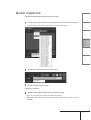
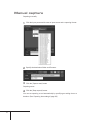
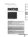
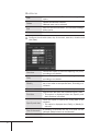
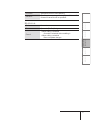
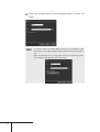
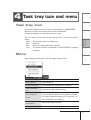
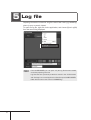
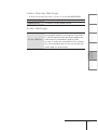
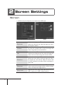
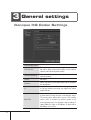
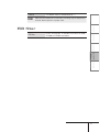
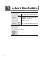
1
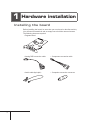
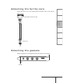
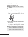
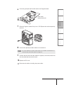
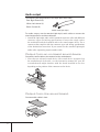
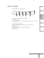
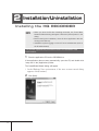
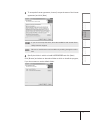
Pegasus Setup Manual September 25, 2007 Copyright© 2007 Thomson. All rights reserved. Cautions (1) It is prohibited to copy a part or all of this product without prior permission. (2) The contents or specifications of this product may be changed without prior notice. (3) We have prepared the contents of this product to the best of our ability; however if you have any questions about the contents, or if there are any errors or missing items, please contact Grass Valley. (4) However we do not take any responsibility for malfunctions arising from use, irrespective of the points outlined in (3). (5) Irrespective of whether it was due to a usage error, Grass Valley takes no responsibility for extraordinary, incidental or derivative claims, including those for lost earnings generated by the application of this product. (6) It is prohibited to analyze, reverse engineer, decompile or disassemble any of the items included with this product, including the software, hardware and manual. (7) CANOPUS, and the corresponding logos are registered trademarks of Canopus Co., Ltd. Pegasus is a trademark of Canopus Co., Ltd. (8) Microsoft and Windows are registered trademarks of the Microsoft Corporation, USA. (9) Adobe, Adobe logo, Adobe Photoshop, Premiere and After Effects are registered trademarks of Adobe Systems Incorporated. (10) Intel, Pentium and Xeon are the trademarks or registered trademarks of Intel Corporation or its subsidiaries in the United States of America and other countries. (11) HDV and HDV logos are the trademarks of Sony Corporation and Victor Company of Japan, Limited (JVC). (12) HDMI, the HDMI logo and High-Definition Multimedia Interface are trademarks or registered trademarks of HDMI Licensing LLC. (13) Other product names or related brand names are trademarks or registered trademarks of their respective companies. Manual Explanation Information not described in this manual may be displayed in some cases. Make sure to read the text file attached to the disc. If there are any variations between the explanation in this manual and the actual application method, priority is given to the actual application method. The screens used as examples in this manual are those of the development stage, so they may vary from those in the final product. This manual is written for people who have a basic knowledge of how to use a computer. If there are no special instructions, perform the same operation as a normal computer operation. In this manual, Microsoft® Windows® XP Professional operating system is called Windows XP Professional or Windows XP. Microsoft® Windows® XP Home Edition operating system is called Windows XP Home Edition or Windows XP. Windows VistaTM Home Basic, Windows VistaTM Home Premium, Windows VistaTM Business, Windows VistaTM Ultimate are called Windows Vista Home Basic, Windows Vista Home Premium, Windows Vista Business, Windows Vista Ultimate respectively, or Windows Vista. Chapter 1 Setup CHAPTER 2 Using HQ RECORDER CHAPTER 3 Settings CHAPTER 4 Appendix CHAPTER 5 Notices & Warranties............................................. 2 CHAPTER 1 1 Before Using.......................................................... 2 Introduction Introduction Contents Contents Support............................................................... 5 Chapter 2 Setup 1 Hardware installation............................................... 8 Installing the board................................................ 8 Attaching the ferrite core....................................... 9 Attaching the gaskets............................................ 9 Part names........................................................ 13 2 Installation/Uninstallation........................................ 14 Installing the HQ RECORDER................................. 14 Installing the Attached Application Software............. 17 Uninstallation...................................................... 18 Chapter 3 Using HQ RECORDER 1 What is HQ RECORDER?....................................... 22 2 HQ RECORDER Main Screen.................................. 23 3 Capture operation................................................. 26 Auto capture...................................................... 27 Manual capture................................................... 28 Scheduled capture............................................... 29 To make the PC enter a suspended state after scheduled capturing ends..................................... 33 Scheduled capturing from a suspended state........... 35 Capturing time settings........................................ 36 4 Task tray icon and menu......................................... 37 Task tray icon..................................................... 37 Menu................................................................. 37 iii 5 Log file................................................................ 38 Chapter 4 Settings 1 Application settings............................................... 40 2 Screen Settings.................................................... 42 Screen............................................................... 42 Position.............................................................. 43 3 General settings................................................... 44 Canopus HQ Codec Settings................................. 44 FIR filter............................................................. 45 Chapter5 Appendix 1 Hardware Specifications......................................... 48 2 Application specifications........................................ 49 iv Chapter 1 Introduction 1 Before Using Notices & Warranties Notices & Warranties Copyright Regulations It is illegal for anyone to violate any of the rights provided by the copyright laws to the owner of copyright, except for fair use (mainly private noncommercial use). Also, in certain cases copying is prohibited with no exceptions. In no event shall Grass Valley be liable for any direct or indirect damages whatsoever arising from the use of captured materials. Warranty This product is covered by a limited warranty when you register your Grass Valley product. This warranty is for a period of one year from the date of purchase from Grass Valley or an authorized Grass Valley agent. This warranty applies only to the original purchaser of the Grass Valley product and is not transferable, Grass Valley warrants that for this period the product will be in good working order. Should our product fail to be in good working order, Grass Valley will, at its option, repair or replace it at no additional charge, provided that the product has not been subjected to misuse, abuse or nonGrass Valley authorized alternations, modifications and/or repair. Proof of purchase is required to validate your warranty. Grass Valley is not responsible for any lost profits, lost savings or other incidental or consequential damages arising out of the use of, or inability to use, this product. This includes damage to property and, to the extent permitted by law, damages for personal injury. This warranty is in lieu of all other warranties of merchantability and fitness for a particular purpose. DANGER CHAPTER 3 Settings CHAPTER 4 Appendix CHAPTER 5 An electrostatic discharge may damage components of this product. Do not directly touch any of the connectors or component surfaces. Static electricity can be generated on clothing and on people. Before handling the product, discharge static electricity from your body by touching a grounded metal surface. Using HQ RECORDER Protect against static electricity Setup This product is not to be used in medical devices or life support systems. The characteristics of this product are not suited for use with such systems. CHAPTER 2 Do not use in environments requiring a high degree of reliability and safety CHAPTER 1 In rare cases, flashing lights or stimulation from the bright light of a computer display or TV monitor may trigger temporary epileptic seizures or loss of consciousness. It is believed that even individuals whom have never experienced such symptoms may be susceptible. If you or close relatives have experienced any of these symptoms, consult a doctor before using this product. Introduction Health precautions Contents The following conditions indicate the potential for serious bodily injury or loss of life. Do not disassemble Do not remove the cover or modify the Product. Fire, electric shock or malfunction may result. For internal inspection or repair, please contact your system integrator or Grass Valley directly. CAUTION The following conditions indicate the potential for bodily harm, damage to hardware or loss of data. Do not setup in areas subject to heat Do not setup in an area exposed to direct sunlight or near a heating apparatus. The heat can accumulate, causing burns, fire or damage. Also, the unit may become deformed or change color. Only setup using the prescribed method Do not setup in a manner other than prescribed. Do not use while wrapped in cloth or plastic. Heat can accumulate, causing burns, fire or damage. FCC Notice This equipment has been tested and found to comply with the limits for the class B digital device, pursuant to part 15 of the FCC Rules. These limits are designed to provide reasonable protection against interference in a residential installation. This equipment generates, uses and can radiate radio frequency energy and if not installed, and used in accordance with the instructions, may cause harmful interference to radio communications. However, there is no guarantee that interference will not occur in a particular installation. If this equipment does cause harmful interference to radio or television reception, which can be determined by turning the equipment off and on,the user is encouraged to try and correct the interference by one or more of the following measures: Reorient or relocate the receiving antenna. Increase the separation between the equipment and receiver. Connect the equipment into an outlet on a circuit different from that to which the receiver is connected. Consult the dealer or an experienced radio/TV technician for help. This equipment has been certified to comply with the limits for a class B computing device, pursuant to FCC Rules. In order to maintain compliance with FCC regulations, shielded cables must be used with this equipment. Operation with non-approved equipment or unshielded cables is likely to result in interference to radio and TV reception. The user is cautioned that changes and modifications made to the equipment without the approval of manufacturer could void the user's authority to operate this equipment. This device complies with part 15 of the FCC Rules. Operation is subject to the following two conditions: (1)This device may not cause harmful interference, and (2) this device must accept any interference received, including interference that may cause undesired operation. Declaration of Conformity According to FCC Part 15 Responsible party Name: Grass Valley, Inc. Address: 711 Charcot Avenue, San Jose, CA 95131 Telephone: 408-954-4500 Declares that product Model:HDRECS complies with Part 15 of the FCC Rules. Customer Support Introduction CHAPTER 1 Setup CHAPTER 2 Using HQ RECORDER CHAPTER 3 Settings CHAPTER 4 Appendix CHAPTER 5 For questions regarding hardware setup and usage, please contact your local Grass Valley office, distributor or the store where you have purchased this product. Contents Support Web-site Including Pegasus, the latest company information is announced at our website: http://www.canopus.com/ The latest drivers utilities, product manuals, FAQs, etc. are also available at our web-site. Online User Registration You can register your Pegasus here. http://www.canopus.com/support/ System requirements PC A PC/AT compatible machine with the following specifications: • CPU: Intel Pentium 4 2.8GHz or higher PCI Express bus Requires a bus slot with the following specifications: • A PCI Express x1 CD-ROM • Required for software installation Memory • 1GB (2GB or more recommended) HDD • Requires a 500MB or larger drive for software installation • Requires a serial ATA 3Gb/s, 7200 rpm drive for capturing Graphic • 1024×768 dpi resolution 32 bit or higher color • Must support DirectX 9.0c Supported OS • Microsoft Windows Vista Home Basic/Home Premium/Business/Ultimate 32 bit • Microsoft Windows XP Home Edition/Professional (SP2) Sound • Requires an internal 4-pin audio input connector to output preview audio. Chapter 2 Setup 1 Hardware installation Installing the board Before installing the board, be sure that your work area is dust-free and dry. You will need a screwdriver and an empty box to hold the removed screws. The following items are required. • Pegasus board • Analog RGB conversion cable • Component conversion cable • Audio cable (4pin-4pin) • Composite conversion connector Attach the ferrite core to the Analog RGB conversion cable in the position shown below. CHAPTER 1 Setup CHAPTER 2 Using HQ RECORDER CHAPTER 3 Settings CHAPTER 4 Appendix CHAPTER 5 Ferrite core Introduction Analog RGB conversion cable Contents Attaching the ferrite core Attaching the gaskets Attach the gaskets to the Pegasus board in the position shown below. Gaskets 1 Shut down the PC and turn the power off. 2 Remove all cables, including the power cable. POINT 3 Make a note of which cables connect to which connectors when removing them. Remove the PC cover. Refer to the PC manual on how to do this. 4 Remove the PCI Express slot cover (PCI Express x1) position to place your Pegasus board. * Refer to your PC manual on the different types of PCI Express slots. * The removed slot cover will not be used during installation. Keep the cover in a safe place. 5 Confirm the availability of a slot in which to install the Pegasus board. Confirm the following: * If the PCI Express x1 slot is not available, the Pegasus board can be installed in either an empty x4 or x8 PCI Express slot. * Be sure not to damage the PCI Express x1 connector on the Pegasus board as it may be damaged by impact or excessive pressure. POINT 10 The Grass Valley board should fit into the PCI Express slot without having to use any significant force. If the board cannot be fully inserted, avoid forcing or bending any part of the board. The board is designed to fit a standard PCI Express slot. If the board does not seem to fit when trying to insert it, do not attempt to force it into the slot. If the board does not easily fit into the slot, try using the other PCI Express slots, or contact your PC or motherboard manufacturer. Connecting the (4pin-4pin) audio cable to the Pegasus board. Contents 6 Setup CHAPTER 2 Using HQ RECORDER CHAPTER 3 Settings CHAPTER 4 Appendix CHAPTER 5 Slide the Pegasus board firmly into a PCI Express slot and temporarily secure it. CHAPTER 1 7 Introduction Audio cable (Unbranched end) 8 Connect the (4pin-4pin) audio cable to a sound device. POINT 9 For more details on audio output (from an on-board sound device or sound board), see "Audio output" on page 12. Confirm that the board and the cables are properly connected, and screw in the bracket that secures the board. 1 0 Replace the PC cover. 1 1 Reconnect the cables, including the power cable. 11 Audio output The following are specifications of the (4pin-4pin) audio cable: Red: Right channel (R) White: Left channel (L) Black: Ground (G) Audio cable (4pin-4pin) For audio output, use the attached (4pin-4pin) audio cable to connect the sound output device and the mainboard. * Attach the (4pin-4pin audio cable) branched-connector cable with different connector types and wiring specifications. Connect the single end to the mainboard and the branched end to the sound output device. Use a connector that complies with the connector type and wiring specifications of the destination connection. If you cannot use the attached (4pin-4pin) audio cable, separately prepare another cable. Output from an on-board sound device Connect the audio cable to the terminal on the motherboard. * Note that an onboard sound device (the sound device integrated on the motherboard: for details, see the instruction manual for your PC or motherboard) might interfere with the board installed in the slot, depending on the position of the connector on the device. Output from the sound board. Connect audio cables in here: 12 Contents Part names Mainboard rear panel Appendix [5] HDMI input port CHAPTER 5 [4] RGB input port Use the supplied RGB conversion cable for connection. Settings [3] Component input connector Use the supplied component conversion cable for the connection. CHAPTER 4 [2] S-VIDEO input port * A composite signal can be input when the supplied composite conversion connector is used. CHAPTER 3 [1] Analog audio input port (stereo mini-jack) Using HQ RECORDER [5] Setup [4] CHAPTER 2 [3] CHAPTER 1 [2] Introduction [1] 13 2 Installation/Uninstallation Installing the HQ RECORDER NOTE • When you boot the PC after installing the board, the "Found New Hardware Wizard" dialog will appear. Select the [Cancel] button in the dialog. • Before starting the installation, close all other applications that are running in the task tray. • Installation requires logging on to the PC as an administrator (such as the PC administrator). This manual explains the procedures used in the Windows Vista environment. 1 Place the application CD into the CD-ROM drive. If the application does not start automatically, open the CD, and double-click "setup.exe" in the [Applications] folder. The "InstallShield Wizard" dialog will appear. * In the Windows Vista environment, if the user account control dialog appears, click [Continue]. 2 14 Click [Next]. To accept the license agreement, choose [I accept the terms of the license agreement] and click [Next]. Using HQ RECORDER CHAPTER 3 Settings CHAPTER 4 Appendix CHAPTER 5 4 Setup Be sure to read the terms and conditions by scrolling through the entire text. CHAPTER 2 NOTE CHAPTER 1 If you do not accept the terms, abort the installation and contact Grass Valley customer support. Introduction POINT Contents 3 Specify the folder in which to install HQ RECORDER and click [Next]. Click [Browse] and select an alternative folder to which to install the program, if you do not want to use the default folder. 15 5 Click [Install]. 6 The driver software installation confirmation dialog will appear. Click [Install this driver software ([Continue Anyway] for Windows XP)]. [Windows XP] 7 Select "Yes, I want to restart my computer now" and click [Finish]. The PC will restart and the HQ RECORDER installation is complete. 16 Install the attached application software, if necessary. Settings CHAPTER 4 Appendix CHAPTER 5 Manual CHAPTER 3 Drivers Using HQ RECORDER CodecOption Setup Applications CHAPTER 2 Adobe CHAPTER 1 The following contents are provided on the application CD. Introduction Application CD contents Contents Installing the Attached Application Software Where Adobe Reader is stored. Where the setup for the capturing application, HQ RECORDER, is stored. Where the setup for the software codecs is stored. CodecOption is automatically installed during HQ RECORDER setup. To play a file captured by HQ RECORDER on another PC, install CodecOption. Where the setup for Pegasus(HDRECS) drivers is stored. Where support documents are stored. 17 Uninstallation Uninstalling the driver and HQ RECORDER NOTE • Before starting uninstallation, close all other applications that are running in the task tray. • Uninstallation requires logging on to the PC as an administrator. In this manual, the procedures used in the Windows Vista environment are explained. 1 2 18 Select [Control Panel] from the [start] menu and click [Uninstall a program]([Add or Remove Programs] for Windows XP). Select [HQ RECORDER] and click [Uninstall] ([Remove] for Windows XP). 4 On Windows Vista, the User Account Control dialog may appear. Click [Continue]. Click [Yes]. CHAPTER 1 Setup CHAPTER 2 Using HQ RECORDER CHAPTER 3 Settings CHAPTER 4 Appendix CHAPTER 5 5 Introduction Uninstallation starts. Contents 3 Select "Yes, I want to restart my computer now" and click [Finish]. The PC will restart and uninstallation is complete. 19 20 Chapter 3 Using HQ RECORDER 1 What is HQ RECORDER? HQ RECORDER is capturing application software, designed specifically for Pegasus. HQ RECORDER is registered in the startup menu, making it memory-resident when the PC boots up. While HQ RECORDER is running, its icon will always be displayed in the task tray. Along with the resident state, HQ RECORDER has several states including capturing, previewing and available to capture. When the HQ RECORDER is resident, you can suspend your PC (sleep, standby mode), so that HQ RECORDER activates to execute timer recording. NOTE 22 • While HQ RECORDER is running, Grass Valley EDIUS cannot be run. • When you want to run EDIUS, terminate HQ RECORDER, or switch it to resident mode and minimize it to the task tray. • Similarly, HQ RECORDER cannot be run while EDIUS is running. Terminate EDIUS, before running HQ RECORDER. • While EDIUS is running, timer recording cannot be executed. (2) Preview Window If the selected format can be previewed, the image will be displayed in this window. Double-clicking on the preview window will switch between full-screen and windowed display. Appendix (1) Preset Click the [Preset] button and select the input source and format to capture. While HQ RECORDER is capturing or preparing to capture, the preset cannot be changed. CHAPTER 5 (12) Settings (11) CHAPTER 4 (7) (8) (9) (10) CHAPTER 3 (6) Using HQ RECORDER (5) Setup (4) CHAPTER 2 (3) CHAPTER 1 (2) Introduction (1) Contents 2 HQ RECORDER Main Screen 23 Displays the status of the input source being previewed. Green Available to capture Red Capturing Yellow Preparing to capture Gray Unable to capture * When copy protection, such as Macrovision and CGMS-A, is detected the following icon will be displayed. (3) Status While the video can be previewed, and audio can be monitored, the “available to capture,” (Green), option will be disabled. Gray Unable to capture Yellow Preparing to capture (When the [Capture start] button is pressed, the status changes to "preparing to capture," but capturing will not start.) * If the input source audio cannot be captured, the following icon will be displayed. While audio can be monitored, it will be muted when captured. Green Available to capture Red Capturing (audio will be muted) Yellow Preparing to capture Gray Unable to capture * If the input source cannot be monitored (an incompatible format for Pegasus to play, input via HDMI), the following icon will be displayed. While audio can be captured, it will be muted when captured. Green Available to capture Red Capturing (audio will be muted) Yellow Preparing to capture Gray Unable to capture 24 (4) Elapsed time Displays the elapsed time since the capturing started. (5) [Capture start] button Click this button to start capturing. (6) [Stop capture] button Stops capturing. If this button is clicked when a scheduled capture (timer recording) is in standby mode, the schedule (recording timer) will be canceled. Appendix Specify the name of the recording file. When this is not specified, the file name will be generated automatically from the date and time. CHAPTER 5 (12)Filename Settings (11)Folder Displays the destination folder where the recorded file will be stored. To change/choose the destination folder, click the [...] button. When HQ RECORDER is started, the folder that was selected when HQ RECORDER was last terminated, will be displayed. By default, the “My Documents” folder is selected. CHAPTER 4 Closes the main screen. CHAPTER 3 (10)[Exit application] button Using HQ RECORDER Opens the captured file with Media Player. Setup (9) [Open file] button CHAPTER 2 Specifies settings for timer recording. The schedule list dialog is displayed. CHAPTER 1 (8) [Open schedule list dialog] button Introduction Opens the hardware settings dialog. Contents (7) [Open configuration dialog] button 25 3 Capture operation There are three methods of capturing with the HQ RECORDER. •Auto capture Captures automatically, detecting the input signal. •Manual capture Captures manually. Two methods for manual capture are a way of starting and ending manually and a way of starting manually and ending automatically by specifying the capturing duration or ending time. •Scheduled capture Captures according to the specified date/time. NOTE To prevent the PC from going into standby mode during capturing, modify these settings including the screensaver setting. POINT The capturing operation • The captured file is created in the folder specified at the [Folder] field. When a name for the captured file is not specified, the date/time information is utilized to generate a file named "mmddhhmmss.avi," where (m:month, d:date, h:hour, m:minute, s:second). • If a file with the same name exists, a dialog will appear, prompting you to overwrite it or rename it with serial numbers. • During capturing, all operations other than stopping, menu operations and switching to full screen/normal screen, are disabled. Each button is grayed out, indicating that the button is unavailable. • During capturing, the application cannot be terminated. Scheduled Capture • While capturing is in progress, other scheduled capturing will not start. • As soon as the current capturing stops/ends, scheduled capturing will start. • During both scheduled and manual capturing, when the stream is interrupted without stopping the process, the captured file will be divided and stored with a serial number. • When the [Stop capture] button is pressed during scheduled capturing, the capturing stops, even though an unprocessed section still remains. The remaining schedule will be ignored. • The ending time of the scheduled capture can be modified with Capture Duration in the popup menu of the task tray icon. 26 Captures automatically, detecting the input signal. CHAPTER 3 Settings CHAPTER 4 Appendix CHAPTER 5 Click the [Capture start] button Using HQ RECORDER 3 Setup Specify the destination folder and file name. CHAPTER 2 2 * Note that the video signal should not be input at this point. CHAPTER 1 Click the Input preset and choose an input source and a capturing format. Introduction 1 Contents Auto capture Capturing is paused. 4 When an input signal is detected, the capturing starts. * Once the input signal breaks, the captureing stops. * When the capturing duration is specified, the capturing continues for the duration. 27 Manual capture Capturing manually. 1 Click the Input preset and choose an input source and a capturing format. 2 Specify the destination folder and file name. 3 Click the [Capture start] button Capturing starts. 4 Click the [Stop capture] button. You can set capturing to end automatically by specifying an ending time or a duration. (See "Capturing time settings" (page 36)) 28 Captures according to the specified date/time. Using HQ RECORDER CHAPTER 3 Settings CHAPTER 4 Appendix CHAPTER 5 The schedule settings dialog opens. Setup The scheduled capturing dialog opens. Click the [Add] schedule button. CHAPTER 2 2 CHAPTER 1 Click the [Open schedule list dialog] button. Introduction 1 Contents Scheduled capture Schedule dialog Current schedule The starting time and the name of the schedule currently being executed will be displayed. Next schedule The start time and the name of the schedule to be executed next will be displayed. LIST Title Displays the schedule name. A file recorded in scheduled capture will be saved with this name. Start date Displays the starting date of the schedule. Start time Displays the starting time of the schedule. Duration Displays the duration of the scheduled capture. Type Displays the type of the scheduled capture: One time, Daily or Weekly. Input Displays the Input preset. Status Displays the status of the scheduled capture as valid or invalid. 29 Buttons Add Creates a new schedule. The schedule settings dialog opens. Delete Deletes the selected schedule. (Multiple items can be selected) Edit Edit the selected schedule. The schedule settings dialog opens. OK Closes this dialog. 3 30 Configure the schedule (date, day of the week, start time, duration) and click [Next]. One time Choose this option to execute capturing only once, according to a schedule. Daily Choose this option to execute capturing every day, according to a schedule. Weekly Choose this option to execute capturing on a specific day of the week at the specified time, according to a schedule. Start date Specifies the date when the scheduled capture starts. End date Specifies the date when the scheduled capture ends. * This option is displayed when the [Specify end date] checkbox is checked. Specify end date Check this option to specify the ending date of the schedule. * This option is displayed when [Daily] or [Weekly] is selected. Day of the week If [Weekly] is selected, the day of a week can be selected. (Multiple items can be selected.) Start time Specifies the time to start capturing. Specifies the time to end capturing. Duration Specifies the capturing duration. Up to 23 hours 59 minutes 59 seconds can be specified. CHAPTER 3 Settings CHAPTER 4 Appendix CHAPTER 5 Cancel • When adding a schedule Cancels the schedule without adding it. • When editing a schedule Does not update changes. Using HQ RECORDER Opens the [Profile] dialog. Setup Next CHAPTER 2 Not used. CHAPTER 1 Back Introduction Buttons Contents End time 31 4 Specify the schedule name and the destination folder, and then click [Finish]. POINT 32 To capture video in a format different from the one selected on the main screen, check [Specify input and format] and choose the preset to use. When the starting time of a schedule arrives, the capturing starts automatically in the specified capturing format. The created schedule is added to the schedule list dialog. 6 Click [OK]. Contents 5 Setup Using HQ RECORDER CHAPTER 3 Settings CHAPTER 4 Appendix CHAPTER 5 1 CHAPTER 2 To make the PC enter a suspended state (Standby/Sleep) after scheduled capture ends, use the following settings. CHAPTER 1 To make the PC enter a suspended state after scheduled capturing ends Introduction When the specified time arrives, capturing starts. Click the [Open configuration dialog] button and open the "Environment Settings" dialog. 33 2 On the Application settings dialog, check [On resident mode go to suspend mode when schedule capturing is finished]. * For detailed information on switching to a suspend state, see page 40. 34 POINT The settings can also be modified from the popup menu (only during a scheduled capture). Right-click on the task tray icon, and check [Go to suspend mode] in the popup menu. NOTE • The system can only be automatically switched when HQ RECORDER is minimized to the task tray. The system will not be suspended when the preview screen is being displayed, when capturing is in progress, or when the system is standing by for scheduled capturing. • If the system is set to be suspended after scheduled capturing ends, a message saying "in ( ) seconds, will be suspended " appears in the task tray icon. Click on the message, or use the task tray icon to cancel suspending the system. Settings Appendix CHAPTER 5 NOTE CHAPTER 4 Suspend the PC to standby or sleep mode. CHAPTER 3 3 Using HQ RECORDER Close the main screen and minimize HQ RECORDER to the task tray. Setup 2 CHAPTER 2 Create a schedule in the schedule settings dialog. CHAPTER 1 1 Introduction To execute scheduled capturing from a suspended PC system, complete the following: Contents Scheduled capturing from a suspended state • To activate scheduled capturing when the system is suspended, suspend the PC with HQ RECORDER minimized to the task tray. You can specify the delay time, if it takes too long to start scheduled capturing after the PC is activated again. You can specify after how many seconds the PC should start up before the specified schedule, in [Wait time for start of capturing] (see page 40) on the settings dialog. 35 Capturing time settings Capturing duration and the ending time can be specified/edited. If the capturing duration is specified, it will be retained as long as the PC is running. 1 Right-click the icon shown at the task tray on the bottom right of the desktop. 2 Choose [Capture Duration] from the menu that is displayed. 3 Specify the ending time of the capture or the capturing duration and click [OK]. Ending time settings 36 Free Run Does not specify an ending time. Duration Specifies the capturing duration in the format (HH: MM:SS. H:Hour, M:Minute, S:Second) This setting is not cleared, even when capturing ends. End Time Specifies the ending time. (HH:MM:SS. H:Hour, M:Minute, S:Second) Specifies/edits the ending time of a capture. Open Schedule List Opens the schedule capture dialog. Go to suspend mode Specifies if the PC will be suspended (standby/sleep) once a scheduled capture has completed. (Available only when scheduled capturing is in progress.) For more information, see "Settings." Version Information Displays the current version. Exit Terminates the application. Appendix Capture Duration CHAPTER 5 Stops capturing. Settings Stop Capture CHAPTER 4 Starts capturing with the selected input presets. CHAPTER 3 Start Capture Using HQ RECORDER Right-clicking on the task tray icon will display a popup menu. Setup Menu CHAPTER 2 The icon shown on the task tray will change color in accordance with its status. White The preview screen is not displayed. Red Capturing. Blue Receiving a signal that can be captured. Gray The preview window is displayed or HQ RECORDER is preparing to capture. CHAPTER 1 Four kinds of task tray icons indicate the current status of HQ RECORDER. When the PC starts, the resident state icon will be displayed. Clicking the task tray icon will display the main menu. Introduction Task tray icon Contents 4 Task tray icon and menu 37 5 Log file Capturing information is stored in a log file named "user name-yyyymmdd.log" where (y:year, m:month, d:date). To open the log file, right-click on the application, and choose [Open Logfile] from the menu being displayed. POINT 38 From HQ RECORDER, you can open only the log file that was created on the day capturing occurred. Log files that were previously created are stored in the "C:\Documents and Settings\user name\Application Data\Canopus\HQRECORDER" folder with the name "user name-YYYYMMDD.log". Chapter 4 Settings 1 Application settings Application settings 40 Wait time for start of capturing Specifies the standby duration before scheduled capturing starts. When HQ RECORDER is in standby mode for scheduled capturing, other operations that modify the scheduled capturing settings or that cancel scheduled capturing are not available. On resident mode go to suspend mode when schedule capturing is finished. Check this option to suspend the PC (standby or sleep) when scheduled capturing ends, with HQ RECORDER minimized to task tray. The PC will not be suspended when a preview is being displayed, when HQ RECORDER is standing by for scheduled capturing, or when capturing is in progress. Action of suspend mode Choose this to switch the PC to standby or sleep mode. * In an environment that does not support sleep mode, the "sleep" option is unavailable. Wait time for going to suspend mode Choose a duration until the PC is suspended, once scheduled capturing ends. Video Overlay Settings CHAPTER 3 Settings CHAPTER 4 Appendix CHAPTER 5 Convert 16Bit/2ch. Check this option to convert audio to 16Bit/2ch. Some editing software only supports 16 bit audio. To edit the captured video with those software, the audio must be converted from 24 bit to 16 bit. In order to retain the compatibility of the created file, we recommend that you do not uncheck this option (keep it in 16 bit format). Using HQ RECORDER Audio Settings Setup Choose the overlay update intervals. CHAPTER 2 Update period CHAPTER 1 Choose the video format. Introduction Video display type Contents * To make the changes take effect, you have to restart HQ RECORDER. 41 2 Screen Settings Screen * Available only for Composite, S, Component or RGB input <Composite, S, Component> 42 <RGB> Brightness Adjusts the brightness. The smaller the value, the darker the video will be, while the larger the value, the brighter it will be. Contrast Adjusts the video contrast. The smaller the value, the less the contrast will be, while the larger the value, the greater the contrast will be. Hue Adjusts the hue. The smaller the value, the more intense the red element will be, while the larger the value, the more intense the green element will be. Saturation Adjusts the color depth. The smaller the value, the fainter the color will be, while the larger the value, the deeper the color will be. When the value is set to 0 (the minimum), the video will be completely in gray scale. Sharpness Adjusts the sharpness of the video. The smaller the value, the blurrier the edges will be, while the larger value, the sharper the edges will be. Setup Level Specifies the NTSC setup level (black level). Set it to 0IRE in Japan and 7.5IRE in North America. Adjusts the screen position horizontally. Vertical Adjusts the screen position vertically. Appendix Horizontal CHAPTER 5 Position Settings • The settings are saved for each input source. • Options that cannot be modified are not available as presets. CHAPTER 4 POINT CHAPTER 3 The default value is marked with an “*”. Using HQ RECORDER Default Setup Specifies the level of noise reduction. CHAPTER 2 Specifies whether or not 3D Y/C separation is active. Noise Reduction CHAPTER 1 Y/C Separation Introduction Adjusts the luminance. Set this to [Manual] to specify the setting manually. Set this to [Auto] to automatically adjust the luminance. Contents Gain Control 43 3 General settings Canopus HQ Codec Settings 44 Online(SuperFine) Not used. Online(Fine) This is the highest quality setting, but the resultant file will be large. Choose this option if you need to capture video of the highest quality. Online(Standard) Normally, sufficient video quality can be obtained with this setting. Offline Not used. Custom When checked, [Q] and [Max Size] will be available for adjustment. Q Adjusts the quality. While the setting range is 4 to 19, the smaller the value, the higher the video quality will be. Max Size Adjusts the maximum bitrate. A video that contains a great deal of noise may be unnecessarily large. To prevent this, adjust this option. The setting value [100] % means the same bitrate as an uncompressed one. For example, with a setting of 1440×1080 60i, 100% is 750 Mbps. To limit this to 200 Mbps, set to [27]%. Default With both Q and Max set to small value, encoding may be delayed and thus fail. Set this option to a proper value. Setup CHAPTER 2 Using HQ RECORDER CHAPTER 3 Settings CHAPTER 4 Appendix CHAPTER 5 Check this option to disable FIR filter at RGB/ YUV444 to YUV422 conversion. CHAPTER 1 FIR filter Introduction FIR filter Contents POINT The default value in marked with an “*”. 45 46 Chapter5 Appendix 1 Hardware Specifications Path PCI Express ver.1.0a 1 lane Digital video HDMI typeA × 1(Ver1.1 HDCP not supported) Analog video Mini DIN7 pin × 1(Analog component) Mini DIN4 pin × 1(S-video, Composit video) Mini DIN9 pin × 1(Analog RGB) Analog audio Stereo mini jack × 1 Output port Analog audio output 4 pin connector for internal PC connection × 1 Current consumption (Maximum) 7.5W Temperature range 0 to 45 degrees C Dimensions (Projecting parts not included) 153.0(W)× 111.2(H)mm Input port * * Signals cannot be input simultaneously from each connector. 48 1280 × 1024/60p *4 1024 × 768/60p 800 × 600/60p 640 × 480/60p Capturing file format Video Capturing resolution Appendix Analog RGB CHAPTER 5 720 × 576/50i Settings 720 × 486/59.94i CHAPTER 4 S-video, Composite video *5 CHAPTER 3 1920 × 1080/50i 1280 × 720/50p 720 × 576/50p 720 × 576/50i Using HQ RECORDER 1920 × 1080/59.94i 1280 × 720/59.94p 720 × 480/59.94p 720 × 486/59.94i Setup Analog component *5 CHAPTER 2 1280 × 1024/60p *4 1024 × 768/60p 800 × 600/60p 640 × 480/60p CHAPTER 1 DVI *2, 3 Introduction Supported Input resolution *1 HDMI *2 1920 × 1080/59.94,60i 1920 × 1080/50i 1280 × 720/59.94,60p 1280 × 720/50p 720 × 480/59.94,60p 720 × 576/50p 720 × 480/59.94,60i 720 × 576/50i 640 × 480/59.94,60p Contents 2 Application specifications AVI(Canopus HQ, LPCM) 1920 × 1080 1440 × 1080(1920 3/4) 1280 × 1080(1920 2/3) 1280 × 1024 1280 × 720 960 × 720(1280 3/4) 1024 × 768 800 × 600 720 × 576 720 × 486 720 × 480 640 × 480 49 Audio Line in, Monitor out *6 Stereo, 24bit/48kHz HDMI input *2, 7 LPCM, 24bit/32, 44.1, 48kHz, 2 - 8ch * 1 Captures in the same resolution that is being input. Up-convert/Downconvert is not supported. * 2 Video and audio in HDCP format cannot be previewed/captured. * 3 Can be connected to the HDMI port with a generic HDMI-DVI conversion cable. * 4 Captured with the video thinned to 30p. * 5 Video that contains copy control such as CGMS-A, CGMS-D, or Macrovision cannot be captured. * 6 Audio will be in Unlocked Audio format, when input in Analog RGB or DVI. * 7 If a mute HDMI signal is input, an AVI file with no audio element will be generated. Audio that contains copy control such as CGMS-A, CGMS-D, or Macrovision cannot be captured. 50