1
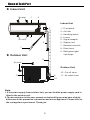
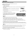
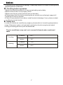
INVERTER SERIE H5
Installation and
User's manual
MUPR-H5
This unit must be installed by a professional according CE 795/2010.
CL20736 to CL20738
English
CONTENTS
Safety Precautions
1
WEEE Warning
4
Name Of Each Part
5
Operation
6
Notices
7
Care and M aintenance
8
Troubleshooting
8
Installation Guide
10
Selection of the installing position
11
Installation of the indoor unit
12
Installation of the outdoor unit
13
Pipe connection
14
Electrical connection
16
Test running
18
Packing list
18
Remote controller
19
IMPORTANT:
Thank you for selectiong super quality Air Conditiones. To ensure satisfactory operation for many ears to come,
this manual should be read carefully before the installation and before using the air conditioner. After reading,
store it a safe place. Please refer to the manual for questions on use or in the event that any irregularities occur.
This Air Conditioner should be used for hosehold use.
This unit must be installed by a professional according CE 795/2010.
WARNING:
The power supply must be SINGLE-PHASE (one phase (L) and one neutral (N)) with his grounded power (GND)
and his manual switch. Any breach of these specifications involve a breach of the warranty conditions provided by
the manufacturer.
NOTE:
In line with the company's policy of continual product improvement, the aesthetic and dimensional characteristics,
technical data and accessories of this appliance may be changed without notice.
Safety Precautions
Incorrect operation due to ignoring instruction will cause
harm or damage. The seriousness is classified by the
following indications:
WARNING
This symbol indicates the possibility of death or serious injury.
CAUTION
This symbol indicates the possibility of injury or damage to
properties only.
WARNING
1.This appliance can be used by children aged from 8 years and
above and persons with reduced physical, sensory or mental
capabilities or lack of experience and knowledge if they have
been given supervision or instruction concerning use of the
appliance in a safe way and understand the hazards involved.
Children shall not play with the appliance. Cleaning and user
maintenance shall not be made by children without
supervision.
2.this appliance is intended to be used by expert or trained
users in shops, in light industry and on farms, or for
commercial use by lay persons.
3.The air conditioner must be grounded. Incomplete grounding
may result in electric shocks. Do not connect the earth wire
to the gas pipeline, water pipeline, lightning rod, or telephone
earth wire.
4.Don't pull out the power plug during operating or with wet
hands.
It can cause electric shock or fire.
5.Don't pull the power cord when pull out the power
plug.
The damage of pulling power cord will cause serious
electric shock.
6.The power plug must be inserted tightly.
Otherwise, it can cause electric shock or overheating,
even fire.
1
7.Children should be supervised to ensure that they do
not play with the appliance.
8.Don't share the socket with other electric appliance,
and use the broken or unstandord cord. Otherwise, it
can cause electric shock even fire.
9.Clean the dust on the plug regularly. Otherwise the
dust mixed, humidity will result in insulation fault even
fire.
10.An earth leakage breaker with rated capacity must be
installed to avoid possible electric shocks.
11.Cut off the main power switch when notusing the unit for a
long time. Otherwise, it may cause product failure or fire.
12.Stop operation and cut off the main power in storm or
hurricane. Operation with windows opened may cause
electric shock.
13.Don't install air conditioner in a place where there is
flammable gas or liquid. The distance between them
should above 1m.
It may cause fire.
14.Don't put a finger, a rod or other object into the air
outlet or inlet.
As a fan is rotating at a high speed, it will cause injury.
15.Don't touch the swinging wind vanes.
It may clamp your finger and damage the driving parts of
the wind vanes.
16.Don't attempt to repair the air conditioner by yourself.
You may be hurt or cause further malfunctions.
17.Take care not let the remote control and the indoor unit
watered or being too wet, or may short circuit even
caused fire.
18.Don't use liquid or corrosive cleaning agent wipe the
air-conditioner and sprinkle water or other liquid either.
Otherwise the inclosure will be damaged even electric
shock.
19.This appliance is not intended for use by persons (including children)
with reduced physical, sensory or mental capabilities, or lack of
experience and knowledge, unless they have been given supervision or
instruction concerning use of the appliance by a person responsible for
their safety.
Cut off the
power supply
switch
Danger
2
CAUTION
1.Don't install the indoor unit under sunshine directly.
2.Don't block air inlet or air outlet, otherwise, the cooling or heating
capacity will be weakened, even cause system stop operating.
3.Don't apply the cold air to the body for a long time. It will deteriorate
your physical conditions and cause health problems.
4.Close the windows and doors, otherwise, the cooling or heating
capacity will be weakened.
5.If the air filter is very dirty, the cooling or heating capacity will be
weakened. Please clean the air filter regularly .
6.It was prohibited to stand or put things onto the top of the outdoor,
to avoid drop or damage. In no case should children be allowed to
sit on the outdoor unit.
7.Set the suitable temperature, especially there are old people,
children and patients in the room. Generally, keep the temperature
difference for 5℃ between the inside and outside.
8.In case that the unit occurs closing down due to the severe
interference from outer environments such as mobile phone, please
cut off the plug and plug in to restart the air conditioner after
several seconds .
9.It is forbidden to let the air conditioner keep precision
instrumentation, artistic production for long time and make food
fresh, otherwise abnormal using will cause damage and weaken.
10.It is forbidden to let children and the disabled use air-condition
without other adult checking.
11.Open windows frequently after using air-condition for a long time.
12.If your air conditioner is not fitted with a supply cord and a plug, an
all-pole switch must be installed in the fixed wiring and the distance
between contacts should be no less than 3.0 mm.
13.If your air conditioner is permanently connected to the fixed wiring
and have a leakage current that may exceed 10 mA. Leakage
protector must be installed in the fixed wiring.
14.The power supply circuit should have leakage protector and air
switch of which the capacity should be more than 1.5 times of the
maximum current.
15. If the equipement emissions cannot meet the technical requirement
of IEC 61000-3-3,Following Attention should be take care.
3
Attention!
Through poor conditions of the electrical MAINS, shortly voltage
drops can appear when starting the EQUIPMENT. This can
influence other equipment (eg. Blinking of a lamp). If the
MAINS-IMPEDANCE Zmax<
OHM(See below form), such
disturbances are not expected. (In case of need, you may contact
your local supply authority for further information).
WEEE Warning
Meaning of crossed out wheeled dustbin:
Do not dispose of electrical appliances as
unsorted municipal waste, use separate
collection facilities.
Contact you local government for information
regarding the collection systems available.
If electrical appliances are disposed of in
landfills or dumps, hazardous substances
can leak into the groundwater and get into
the food chain, damaging your health and
well-being.
When replacing old appliances with new ones, the retailer is
legally obligated to take back your old appliance for disposals
at least free of charge.
4
Name of Each Part
★ Indoor Unit
Air inlet
1
2
Indoor Unit
3
1、Fron t pan el
2、A ir filter
3、H andling switch
Air outlet
4、Louver
5
4
5、S ign al receptor
6、S upply c ord
6
7、R emote controller
7
8、D rain hos e
9、R efrigerant gas/
★ Outdoor Unit
liquid pipe
9
Air inlet
Outdoor Unit
10、 Cut-off valve
11
8
11、 Air outle t cover
10
Air outlet
Note:
1.If the power supply from outdoor unit, you can find the power supply card is
fitted in the outdoor unit.
2. The descriptions in this user manual are text and figures may have slightly
difference to the promotion information and actual appliance. Please refer to
the real appliance purchased, Thank you .
5
Operation
★ Remote controller operation
Se e "air conditioner remote con troller in struction "
★ Manual operation
☆ Manual op eration
When the remote controller does not work or can not be found, please follow
these steps:
1.As the unit is ope rating, you c an press the "Auto button "
to stop operating.
2.As the unit is stopping, you can press the "Auto button "
to start operating.
☆ Ad justing air flow direction
1. Adjusting h orizon tal air flow manu ally.
U se your hands to move the vertical airflow
vane and change the horizontal wind
direction.
! Note:
a. Adjust the horiz ontal air flow direction before
the air-conditioner sta rts. Don ' t insert your finger
into air intake or outlet vents when the air-conditioner is operating.
b. For appliance w ith auto pendulu m wind function, please refer to " air
conditioner re mote controller instruction " for how to adjust horizontal air flow.
2. Adjusting vertical air flow direction(up-down)
3
Refer to "air conditioner rem ote controller instruction " for how to adjust vertical
airflow direction through adjusting the horizontal airflow vane by remote controller.
!Not e:
Adjust the vertical air flow direction by remote controller. When you adjust the
horizontal airflow vane by hand, the machine m ay cause problem.
Manual operation can be used temporarily in case you can not use remote
controller or its batteries are exhausted.
When the air-conditioner stops, the horizontal wind vane will close the w ind
8
outlet of air conditioner.
6
Notices
To prevent injury and property damage, Please pay attention to these following before
operating the air conditioner.
★
Checking before operation
1.Make sure tha t the earth w ire is connected safely and reliably.
2. Make sure the filter net is properly fixed.
3.Make sure that air outlet an d inlet are not blocked.
4.P lease clean the filter before starting th e air-conditioner referring to page to 6
" Cleaning " for ho w to operate .
5. Check to see whether the outdoor install bracket is damage. If yes, please contact
our Service center locally.
★
Safety tips
In o rder to u se the air con ditioner properly, please refer to its working te mp erature
rang e. O the rwise, indoor unit automatic protection fun ction may be activated,
coo ling or he ating efficiency will be weakened.
,
The a ir-conditioner may can t run in normal follo wed under mention ed
table
O utdoor
>47℃
Indoor
<18℃
O utdoor
<-12℃
Indoor
>30℃
C ooling
H eating
7
Care and M aintenance
★
Cleaning
☆ Cleaning the indoor unit
1.Turn off the a ir-conditioner and re move the electrical p lug from the outle t.
2.Wipe the indoor unit with dry cloth or wet cloth which is dipped b y cold water.
! Note :
Don't use water above 45℃ to wash the panel, or it could cause deformation or depigment.
Don ' t use thinn er, polishing pow der, benzen e and oth er volatile chemicals.
Don't use liquid or corrosive detergent clean the appliance and don t splash water or other
liquid onto it , otherwise, it may damage the plastic components, even cause electric shock.
☆ Cleaning air filter
Front pane l
Front panel
Air filt er
Air filter
1.Raise up the fron t panel of indoor unit until it su ddenly stop, then raise u p the
protrude d part of air filter, and then ta ke it out.
2. Use a vacuum cleaner or wash them with water, th en dry it in the shade.
3. Reinsert the air filter into the indoor unit u ntil being en tirely fixed, then close the
front panel.
★
Maintenance
1. Select "FAN " ope ration m ode,
make the air conditio ner run a
long time to dry.
2. Turn off the air conditioner and cut
off the pow er supply.
3. Take out the batterie s from the remote
controller.
4. Cle an air filters and other parts.
Troubleshooting
Check the following before requesting on service centre if the malfunction occurs.
Phenomenon
Air conditioner dose
not operate at all
Trouble shooting
Has the power been shut down?
Is the wiring loose?
Is the voltage higher than 1.1 times of max rated voltage
or lower than 0.9 times of min rated voltage?
Is the fuse burnt?
Does it reach the set time for start up?
8
Troubleshooting
Phenomenon
Remote controller is not availa ble
Is the remote controller out of effective
distance to the indoor unit?
Is the battery exhausted?
Are there any obstructions between the
controller and the signal receptor?
Cooling (Heating)efficiency is not
good
Is the setting temperature suitable?
Is the air inlet or outlet obstructed?
Are air filter dirty?
Is indoor fan speed set at low speed?
Is there any heat source in your room?
Indoo r unit does not operate
immediately w hen the air
conditioner is restarted
Once th e air conditioner is stopp ed,
it will not operate in approximate ly
3 minutes to pro tect itself.
There is u nusual smell blowing from
the outlet after operation is started.
This is caus ed b y the odour in the
room perme ated from building
material, furnitu re, or smoke .
Sound of water flo w can be heard
during cooling operation
This is caus ed b y the refrigerant
flow ing inside the unit.
Mist is emitted during cooling
operation.
Because the air of the room is cooled
down rapidly by the cold wind and it
looks like the fog.
Mist is emitted during heating
operation.
This genera te due to mo isture in
defrosting process.
Low n oise can be heard during
operation
A lo w hissing sound is cause d by
the refrigerant flowing.
A lo w squea k so und is caused by
the deformation of p lastic du e to
tem perature.
In case the fo llow ing situation, p lease immediately stop all operations and
cut off the power supply, then contact w ith serv ice c entre .
Th e fuse and sw itch ofte n breaks.
Carele ssly splash wate r or some thing into air conditioner.
Unusua l noise c an be h eard during o peration.
Electrical wiring an d power plug are very hot.
Wind b lowing from the outlet sm ells terrible d uring op eration.
Th e Run light o r other display fla shes rapidly and kee ps flashing after repluging.
9
Installation Guide
★ Guide for customer
1.Please read the instructions carefully before installation of the
air-conditioner.
2.The installation should be carried out by specialists.
3.Installation the air-conditioner and connecting the pipe and
wires must be strict to reference the instructions.
4. The wiring must be done by qualified electrician according to
the electrical safety requirements.
5.The customer should have a qualified power supply which
coincides with the tag of air conditioner, the normal voltage
should be in the range of 90-110% of its rated voltage.
6.The air conditioner must be well grounded, the switch of the
main power of air-conditioner must be reliably grounded.
★ Notices
1.The air conditioner must be installed on well strong
supporter.
2.The appliance shall be installed in accordance with
national wiring regulations.
3.Fix the machine firmly, other wise it will produce abnormal
noise and vibration.
4.Install the outdoor unit in the place where it wouldn't
disturb your neighbour.
5.The method of connection of the appliance to the
electrical supply and inter connection of separate
somponents, please see the electric connection elements
shart which stick on the machine.
6.If the power supply cord is damaged, it must be replaced
by the m anufacture or its service agent or a similar
qualified person.
7.After installation, the power plug should be easily reached.
10
Selection of the installing position
★
Indoor Unit
● There is no heating and
steaming source nearby.
● No obstacles for insta lling
position nearly.
● Keep good air circulation.
● Convenient to adopt
meas ures to reduce noises.
● Do not install them ne ar the
doorway.
● Make sure to have the
distance betw een the ceiling,
wall, furniture and other
obstacles.
● 2 meters high above the floor.
★
Above
15cm
Above15cm
Outdoor Unit
● In case that you p ut up a canopy to protect
it from rains and sunrays, pay atte ntion no t
to ca use any obstacles for the heating
dispersion for the conden ser.
● Do not grow animals or plants near the
insta llation location for the co ld and hot air
out w ill affect them.
● Make sure to have the distance sp ecified
in the pic ture between ceiling, wall,
furniture and other obstacles.
● Stay awa y from heating source and
inflammable air.
● The installation base and supporting frame
shou ld be strong and secure. The machine
shou ld be at plane su rface.
Above 30cm
The unit comes preloaded for liquid pipe lengths less than 5 m. For greater lengths see table below:
Pipe lenght
Additional charge (R410A)
No need additional charge
Less than 5m
Models 9k y 12k
More than 5m
Model 18k
R410A: (Lenght - 5) x 20g/m
R410A: (Lenght - 5) x 30g/m
The maximum total pipe length is 15 m.
The maximum vertical length is 5 m.
The diameters of the pipes are:
Model
Pipes
MUPR-09-H5
6.35 (1/4") - 9.52 (3/8")
MUPR-12-H5
MUPR-18-H5
6.35 (1/4") - 12,7 (1/2")
6.35 (1/4") - 15.6 (5/8")
11
Installation of the indoor unit
●First make chan ges to wall a nd make sure that is hard
and secure. Using four "+" type screws to fasten the
installation board on to the wall. Keep it w ater lever
horizontal direction and perpendicular in vertical
direction. O therwise it might cause water drops when
air-conditioner is running cooling operation.
●Pu ll out the indoor unit p ipes after
detached the fixed parts on them.
Connect the interconnected pipe s to
the indo or unit: point to the cente r of
pip e and fasten the conn ection screw
at first by ha nd and then by wrench
until yo u hear the " Click " sound.
Fastening direction is sh own in the
right pic ture. Using torque is shown
in the following table.
Wall
Pipe
connec tion
15mm
Ri ng
Connection pipe
Nut pipe
Spanner
70 ho le
Drilling 70mm diameter
pipe hole at the left down
or right down side of the
installation board. The
hole shall slant outward
slightly.
Sp anne r
Remove the base
support foam in one side
before installation.
Wall
Drain pipe
Connection pipe
Base
Wall
Air-conditioner
Connection pipe
Foam
Plastic strap
Cable
Cable
Connection
pipe
Outflow tube
Cabl e
Installation
board
Cable
Outflow tube
Note : The ins talled air-conditi oner
won 't be tigh tly appressed to the
wall if that is not arran ged sho wn in
the p icture. The outfl ow tube must
be in the bott om and t he highe st
poin t of it can not exc eed the
posi tion of w ater basin.
Installati on board
●Arrange the connection pipes, cable, outflow tube according to the figure , then
connect the drain pipe to the draining hole.
●Use insulation sleeve to warp the position of connection pipe and indoor unit, then
wrap the insulating tape on the sleeve to avoid conden sate water.
●Fasten connection pipes, cables and drain pipe together b y plastic strap.
Con nection wire
Water dischar ge pipe
12
●Hang the indoor unit to the board
an d make sure the machine is in
the middle of the board.
●Pu shing the machine towards the
left down and right down side of
the installation board until the
ha ngers enters tightly the grooves
(it makes "click " sound)
★
Check the water discharge
1. Take off the fram e the unit cover.
Take off the front frame for maintenance
according to the follow ing steps:
● Turn perpendicular airflow direc tion handle
from " I " to horizon tal direction.
● As shown in the picture on the right, take off
two covers from the front frame and then
unfasten two fixture screws.
● Pull the front frame towards yourself and take
it off.
In case that put the fro nt frame back, turn the
perpendicular airflow direction handle from
" I " to horizontal, then pro ceed according to
the th ird and the second steps.
You should check whether the front frame is
firmly inside the fixture groove on the top.
2. Check the water dis charge.
● Put a cup of water into groove.
● Check whether the water flo w th rough th e
water discharge hole.
Bolt Ver tical airflow
dire ction plate
Bolt
Front frame
Pull d own the front frame towards your
and ta ke off the fro nt frame.
Installation of the outdoor unit
● The ou tdoor un it must be firmly fixed to avoid falling in th e strong wind .
● Ins tall on the cement base the drawing below.
● If it will be installed at seaside or at a pla ce h igh above th e gro und and with strong
win d, the AC should be installed aga inst the w all to ensure the normal operation of
the fan and the blocking plate should be used.
● If it will be installed in ty pe, the structure of the m ounting surface should be made
of solid stick, cement or materials with equivalent strength, and be of e nough
bearing capacity. Otherwise, measu res such as reinforcement, support or
vibratio n damping should be adopted.
Installation outdoor unit bolt
Model
Outdoor U nit Size of
Shape (mm )
A (mm)
B (mm)
09 K
720 X 260 X 540
539
287
12 K
760 X 260 X 540
539
287
18 K
800 X 300 X 690
540
226
Left installation feet
Right installation feet
Air inlet
A
Air outlet
Outdoor Unit
13
Pipe connection
● Connect the pipe to the unit: point to the
center of pipe and fasten by wrench
until it is tightly
The size of pipe Torque
fastened, the
_
fastening
6.35mm( 41 ) 18N.m
direction is in the
_
following picture.
9.52mm( 83 ) 42N.m
_
12.7mm( 21 )
_
15.88 mm( 5
8
Indoor unit
Connection screw Pipe
55N.m
) 75N.m
● Pointing towards the center of pipe, fasten
the screw with strength.
● Wrench the screw in the end until you hear
the “Click” sound.
Wrench
Torque
wrench
Connection screw
Outdoor unit
Side liquid pipe
Side air pipe
Refer the direction to the picture
★
The form of pipe
U se sealing ta pe to
co ver the sma ll leaks
on the externa l ring
of the pipe
Torque wrench
Round s hape
Wrap up with tape
Use sealing tape to
cover the s mall leaks
on the exte rnal ring of
the pipe
Pipes
Water discharge
pipe
Connection wire
Control panel cover
Round shape
Connection wire
Roun d in this sha pe to preven t water
entering the electrical parts
● Wrap up all pipe , water discharge and
connection wire from top to below.
● Cover the connection and fix them w ith
two plastic rings.
● Wrap up the pipes with tape alon gsid e
the wall and fix them to the w all with
clip s. T hese steps are u sually adopted
when outdo or unit is installe d be low the
indoor unit.
14
See the picture
on the left
● In case that you want to have
additional water d isch arge pip e, the
end of pipe should be within certain
distance towards to surface ( don 't let
it under the water. Fix it onto the wall
so it won ' t be swayed by the wind).
● Wrap the pipes and connection wire
w ell from below to top.
● Wrap up the pipes that are rounded
up by the wall comers in the way
shown in the picture so it can prevent
w ater entering the roo m.
● Use clips or other fixture to fasten the
pipes to the walls.
★
Expelling the air in the pipes and the indoor unit
Expelling the air: humid air in the
Outdoor unit
refrigerating system m ight cau se troub le
of compre ssor.
● Take off the cover from the s top valve
and T-branch valve.
● Take off the aux iliary cover from the
T-bran ch v alve .
● Turn the stop valve rod anti-clock wise
to an angle of 9 0 degree, keep it open
To indoor un it
for 8 secon ds a nd close the valve.
Liquid side
● Check whether there is air leakage at Vapor side
Gas side
all connection parts of pipes.
Stop valve(ope n)
● Push the to p rod of T-branch valve by
hexagon wrench to expel air.
● Repeat the third and fifth steps.
Cover
● Open the stop and T-branch valv e with
a h exagon wrench to make the unit
operate.
● There is no leakage allowed, please
check all the piping con nection parts.
T-branch valve(open)
You must test the leakage, generally, Auxiliary cov er Hexagon wrench
it c an be tested by soap water.
● If the A/C is filled w ith R410a, make sure to dis cha rge air and moisture
remain ing in th e re frigerant sy stem with a vac uum pump.
(For metho d of usin g a manifold valve, refer to its operation manual.)
1.comp letely tighten the flare nu ts, A , B, C, D , connect the manifo ld valve charge
hose to a charge port of the low-pressu re valve on the g as p ipe side.
2.C onnect the charge hose connection to the vacuum pump.
3.Fully open the handle Lo of the ma nifold valve.
4.O perate the vacuum p ump to evacuate. After starting evacuation, slightly loo se
the flare m ut of the Lo valve on the gas pipe side and check that the air is entering
(O peration noise o f the vacuum pum p changes a nd a compound meter indicates
0 instead of minus.)
Refrigerant
Indoor
5.A fter the evacuation is com ple te, fully
Outdoor
unit
unit
close the hand le Lo of the m anifold valve
A
Gas side
C
and stop the opera tion of the vacuu m
Liquid side
D
pump. Make evacu ation for 15 minutes or
B
Half union
more and check that compound meter
Packed valve
5
indicates -76cmHg (-1×10 Pa).
Manifold valve
6.turn the stem of th e packed valve B about
Compound meter Pressure gauge
45 counte rclockwise for 6~7 secon ds
-76cmHg
after the gas coming out, then tighten the
flare n ut again. Ma ke suer the pressure
display in the pressure indicator is a little
Handle Hi
higher than the atm osphere pressure.
Handle Lo
Charge hose
7.R emove the charge hose from the Low
Charge hose
pressure charge hose.
Vacuum pump
8.Fully open the packed valve stems B
and A.
9.S ecurely tighten the cap o f the packed
va lve.
Low pressure valve
15
Electrical connection
Power wiring and interconnection must meet:
model
09K
12K
18K
24K
Specification of
connection cables
(mm2 )
2 x 2.5 + T
2 x 2.5 + T
2x4+T
2x4+T
The power supply (230V - 50Hz) is connected only to the indoor unit.
Indo or c onn ection
O pen the front panel, inset the con nection cables from the base of the
air-co nditione r, conne ting to the te rminal board in order (according to th e gra ph),
using the pressing board to fasten the connection cables.
Front panel
Pres sing board
Bottom frame
Mid-fra me
Connection cables
Connection cables
Open the front pa nel, if the indoor unit is fitted with the signal wire, please detach
the mid-frame,and insert the signal wire through the bottom frame, then connect the
signal wire quick plug of the in door's to the outdoor's.
Outdoor connection
● Unscre w th e screw, take off the control panel cover from the u nit.
● Accord ing the connect position of ind oor unit, make sure the c onnection cables
connet to th e board of outdo or un it co rresponding .
● The grounded wire connection:
1.loosen the ground ed screw of e lectric bracket.
2.C onnect the g rounded wire with the grounded screw then setscrew in the " "
mark form erly.
● Fix the cable to the term inal boa rd w ith pressing board.
● Reinstall th e co ver with the scre w.
16
Cover
Te rm inal board
Te rmin al boa rd
Grou nde d w ire
Electric bracket
Electric bracket
Pre s sing b oa rd
Pre ssing b oa rd
N OT E:
※ Conne ct th e gro unded w ire correctly, otherwise will c ause the ma lfunction of some
electrical componet and sho ck o r fire ind eed.
※ Don't reverse the po wer polarity.
※ Must fix the screwn ail o f the firm ly w ire, then drag the wire lightly, confirmation
whether it's firm ly.
※ If there is a connector, connect it directly.
The c onn ection of co nne ctio n cables of indoor unit and outdoor unit must
corre spo nd (from the graph in down), otherwise, it c ould be cau se s hoc k or fire .
Indoor Unit
Outdoor Unit
Brow n= Live wire
Blue= Zero line
Yello w/Green= Grounded wire
NOTE:
This manual is usually includes all the wiring mode for the different kind A/C,
please refer to the corresponding guide and instruction when wiring. We cannot
exclude the possibility that the product should be improved and caused the
change of wiring, please refer to the wiring diagram adhered on the A/C purchased.
17
Test running
● Make su re that p ipes and wire s are connected.
● Make su re that liquid side valve and air sid e valve
both are completely open.
1. The con nection of p ower source
● Con nect the wire to in dependent power source socket.
● Prepara tion of remote controller.
● Run the air-conditioner in cooling operatio n mode
for 3 0 minutes or longer.
Discharged air
2. Performanc e evaluation
● Test the out and in air temperature.
● Make su re w hether th e ou tlet air temperature s ubtract from inlet s gives more
than 10℃ 。
Packing list
● Please check the fo llow ing attach carefully, if pa rt attach isn t useful, please take
ca re of it.
Packing list of the indoor unit
N O.
N ame
Unit
Quantity
1
Indo or u nit
Set
1
2
Remote controller
PC
1
3
Instructions
PC
1
4
Batteries
PC
2
5
Dra in pipe
PC
1
6
Certificate
PC
1
Packing list of the ou tdoor unit
N O.
N ame
Unit
Quantity
1
O utdoor unit
Set
1
2
Connectio n pipe
PC
2
3
Plastic strap
ROLL
1
4
Pipe protection ring
PC
1
5
Luting (putty)
PACKE T
1
6
Certificate
PC
1
18
Remote Controller
AIR-CONDITIONER REMOTE
CONTROLLER INSTRUCTIONS
AUTO
自动
COOL
制冷
除湿
DRY
制热
HEAT
FAN
自动
自动
HIGH
制冷
制冷
除湿
除湿
MID
制热
制热
LOW
ON/OFF
SET
MODE
CLEAN
SPEED
SLEEP
FRESH
STRONG
SWING
DUST
FEELING
HEALTH FUNGUSPROOF SCREEN TIMER
Read this “instructions” carefully so that
you can use the air-conditioner safely and
correctly.
● Take good care of the “instructions” so
that it can be referred to at any time.
●
19
Remote Controller
Buttons description
LCD displays ins truction
TRANSM IT DIGITAL O N/OFF
AU
TO
自动
COOL
制冷
DRY
除湿
制热
HEAT
FAN
自动
自动
HIG
H
制冷
制冷
MID
除湿
除湿
制热
制热
LOW
SE T
ROO M
RUNNING
MODE
RUNN ING
MO DE
SPEED
TIMER O N OFF
ON/OFF
9
10
1
SET
MO DE
CLEAN
SPEED
SLEEP
FRESH
STRONG
SWING
DUST
FEELING
11
2
3
12
4
13
HEALTH FUNGUSPROOF SCREEN TIMER
5
6
14
7
15
8
TIMER
FEELING
O N/O FF display:
w hen the remote controller is
the on sta te, th e LC D w ill be
displays otherwise will not be
display.
D igital display:
U nder the state of normal
w orking. It dis plays se t
temperature, w hile the fee ling
function is sta rt. It will disp lays
room tempera ture , and und er
the state of timer mode. It w ill
displays set timer.
1.“ON/OFF” button
You can start the air-cond itioner b y pressing this button
and stop its operation by p ressing it ag ain.
2.“FRES H” button
This button is inva lidation.
3.“SPEE D” button
You can select fan spe ed show as the follow:
Low
Mid
High
Au to
4.“ STRONG”button
O nly under the state of cooling or heating mode, press this
button, the fan speed is adjusted to strong auto-maticlly and
the LCD d isplays “high fa n”, the “strong ” function is
starte d to reach th e highest co oling or heating.
20
Remote Controller
5.“FEELING” button
When it displays “FEELING” button :
Pres s this bu tton can be used to set the feeling function.
The LCD sho ws the a ctual room temperature when the
function set and it shows the setting temperature when the
function cancelle d. This function is invalid when the
appliance at the Fan mode.
6.“DUST” button
This button is invalidation.
7.“TIMER” button
Setting the “ON” timer time:
a. When remote controller is at off state, pr ess “TIMER”
button, the LCD displays “TIMER ON” and the ti mer
time, the range of setting time is 0. 5h to 24h.
b. You can press the “ ” or “ ”button t o adjust the
timer time, each t ouch will be set time t o increase or
reduce 0.5h before 10 hours ago, after ten hour s will be
set time to increase or reduce 1h per pressing, to enables
your required timer.
c. Press “TIMER”button again, to set the t imer on function.
d. You can set another function to insure the suit able state
after air conditioner turn on (including mode, t emperature,
swing, fan speed and etc). The LCD will displays all your
setting and keep it, when the timer reach to the set time,
the air condit ioner will be working according to your set
automatically.
Setting the “OFF ” timer t ime:
a. When remote controller is at on state, pr ess “TIMER ”
button, the LCD displays “TIMER OFF ” and the timer
time, the range of setting time is 0. 5h to 24h.
b. You can press the “ ” or “ ”button t o adjust the
timer time, each t ouch will be set time t o increase or
reduce 0.5h before 10 hours ago, after ten hour s will be
set time to increase or reduce 1h per pressing, to enables
your required timer.
c. Press “TIMER”button again, to set the t imer off function.
8.“SCREEN ” b utton
You can let the LCD d isplays work ing or not by pressing this
button.
21
Remote Controller
9.“
”or “
” button
Press the “+”or “-”button,you can set the temperature
range from 16℃ to 32℃,Display will change as you touch
the button.
10.“CLEAN” button
a. When remo te controlle r is at the off state, press“clean”
bu tton , the win d guiding ba rs turn to initial p ostio ns for
co oling, the A/C runs“c lea n”fu nction w ith max dura tion
35 mins.Th e purpose of its function is to clean dust o n
ev aporator and dry the insid e w ater of e vapo rato r and
to prevent the evaporator g oing moldy due to water
de position and boastin g strange sm ell.
b. After setting “clean”function, press“c lea n”button
ag ain to cance l “clean ”fu nctio n or press “ON /OFF ”
bu tton to cancel “clean ”fu nction and start A/C .
c. The cle an function will be no working after 35 minutes
runnin g workin g without an y op eration.
N ote:“clean ”function can be set in parallel with
“time start” function; in this case , “time start”
function will be executed after“clea n”function.
11.“MODE” button
Which enables you to select different operation mode,
after each pre ssin g, the operation mode will be changed. It
shows in the following display.
AUTO→C OO L→D RY→HEAT→ FA N→AUTO
R emark: cold wind type has no heating function.
12.“ SLEEP” button
1.press the SLEEP button , the sleeping indicator light of
indoo r unit flashes on.
2.after the setting of sleep ing mode, th e co oling operation
enables the set tempe ratu re to increas e 1℃ after 1hour
and another 1 ℃ autom atically after 1 h our.
3.after the setting of sleep ing mode, th e he ating op eration
enables the set tempe ratu re to dro p 2℃ after 1hour and
another 2 ℃ autom atic ally after 1 hour.
4.the air-conditioner runs in sleeping m ode for 7 ho urs and
stops automatically.
R emark: press the MODE or ON/OFF button, the remote
controller clears sleepin g mode awa y.
22
Remote Controller
13.“SWING” button
Press this button, the horizontal wind direction vanes can
rotate automatically, when you have the desired vertical
wind direction, press it again, the horizontal wind direction
vanes will be stopped at th e situation of your choice.
14.“HEA LTH ” button
Press this button, you can turn on or off the health function.
15.“FUNGUSPROOF” button
T his A/C has special d ry an d anti-mold function which
has “ yes ”or“no ”tw o selections. Th is fu nctio n is
controlled by the remote controller und er cooling, d ry and
auto (cooling and dry) modes, the horizontal wind g uiding
bars are at the initial p osition for coolin g. T he A/C ru ns
under heating mode(the cooling only A /C only runs under
fan mode), the interna l fan runs for three minutes with w eak
w ind before stop. The purpose of th is fu nction is to dry the
inside of the e vaporator and to prevent the evaporator from
going mouldy due to w ater deposition and thus dispersing
strange smell.
Note:
1.This function has not been set i n the factory. You ma y
freely set and cancel this function. The set ti ng method
is: under “off”status of the A/C a nd the remote
controller, point t he remote controller toward t he A/C
and continuously press “FUNGUSPROOF”pushbutton
for one time, the buzzer keep beeps five times again
after fiv e times beeps, indicating t hat this function is
ready. In case this function has been set, unless the
whole A/C is powered off or the function i s manuall y
cancelled, the A/C then has this f unction as a default;
2.To cancel the function: 1. Power off the whole A/C; 2.
Under “of f”status of th e A/C and the remote
controller, point t he remote controller toward t he A/C
and continuously press “FUNGUSPROOF”pushbutton
for one time, the buzzer keep beeps three times again
after fiv e times beeps, indicating t hat this function has
been cancelled;
3.When this function is on, it is suggested not t o restart
the A/C before it is completely stop;
4.This function will not run in case of time stop or slee p
stop.
23
Remote Controller
Usage
Fix batteries
1.Slide open the cover according the direction indicated
by arrowhead.
2.Put into two brand new batteries (7#), position the
batteries to right electric poles (+&-).
3.Put back the cover.
Automatic operation mode
1.Press the MODE button, select the automatic operation
mode.
2.Press the SPEED button, you can select fan speed.
You can select fan speed from LOW, MID, HIGH, AUTO.
3.Press the ON/OFF button, the operation indicator is on,
the air-conditioner starts to operate the automatic mode.
Press the button again, the air-conditioner stops.
Cooling/Heating operation mode
(cold wind type has no heating function)
1.Press the MODE button, select the C ooling or Heating
operation mode.
2.Press the “ ” or “ ” button, set the temperature,
temperature can be set at 1℃ difference range from
16-32℃.
3.Press the SPEED button, you can select fan speed.
You can select fan speed from LOW, MID, HIGH, AUTO.
4.Press the ON/OFF button, the operation indicator is on,
the air-conditioner starts to operate the automatic mode.
Press the button again, the air-conditioner stops.
24
Remote Controller
Fan operation mode
1.Press the MODE button, select the C ooling or Heating
operation mode.
2.Press the SPEED button, you can select fan speed.
You can select fan speed from LOW, MID, HIGH.
3.Press the ON/OFF b utton, th e operation indicator is o n,
the air-condition er starts to operate the a utomatic mode.
Press the button again, the a ir-conditioner stops.
R emark: In the circulatio n operation mode, to set the
tempera ture is noneffective .
Drying operation mode
1.Press the MODE button, select the D ry opera tion mode.
2.Press the “ ” or “ ” button, set the temperature,
temperature can be set at 1℃ difference range from
16-32℃.
3.Press the SPEED button, you can select fan speed.
You can select fan speed from LOW, MID, HIGH, AUTO.
4.Press the ON/OFF b utton, th e operation indicator is o n,
the air-condition er starts to operate the a utomatic mode.
Press the button again, the a ir-conditioner stops.
Night Luminous Function of Remote
Controller(Only the remote controller with
this function can be used)
For your convenient use of the remote controller in the
darkness without any lighting, this remote controller has
blue backgro und light and luminous pushbuttons. Function
at yo u press on a ny o f the pushbutton, the background light
will immediately release soft light so that you are easy to
operate the remo te controller. If you do not operate the
controlle r within 10 seconds, the background light will
automatically dis appear.
N ote:
A ll the figures ab ove are the displays after b eing
initially e lectrified or re-elec trified a fter pow er off. In
actual op erations, th e remote co ntroller screen
displays related items only.
25
Remote Controller
Attention
1.Aim the rem ote con troller toward s the receiver on the airconditio ner.
2.The rem ote controller s hould be within 8 meters away
from the receiver.
3.No obstacle s be tween the re mo te controller and receiver.
4.Do not drop or throw the remote con trolle r.
5.Do not put the remote co ntro ller under the forceful
sunrays or h eating facilities and othe r heating sources.
6.Us e two 7# batteries, do not use the electric batteries.
7.Take the batteries out o f rem ote controller be fore stop its
using for lon g.
8.When the noise of transmitting signal can’
t be heard
ind oor u nit or the transmission symbol on the display
screen doe sn’
t flare, ba tterie s need be re placed.
9.If reset phenom enon occurs on pressing the button of the
remote con trolle r, the electric quantity is deficient and
new ba tteries n eed to be sub stituted.
10.The w aste battery sho uld be disposed properly.
26
Notes
27
ASK FOR MORE INFORMATION:
Phone: +34 93 446 27 80 - Fax: +34 93 456 90 32
eMail: [email protected]
TECHNICAL ASSISTANCE:
Phone: +34 93 652 53 57 - Fax: +34 93 635 45 08