1
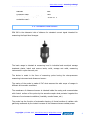
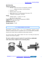
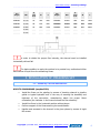
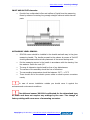
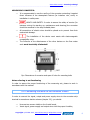
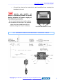
MEASURE SET OF LIQUID INTENSITY FLOW
MANUAL
Flowmeter
FLOWBOX
- FLOW MEASURING CONVERTER M1600
- ULTRASONIC SENSOR SPA 380
Flume
PALMER-BOWLUS ZPB500
Wrocław 2015
www.di-box.com.pl - Instrukcja obsługi
------------------------------------------------------------------------------------------------------------------------------------------------------------------------
Thank you for choosing product of our firm.
The DI-BOX company guarantees the big quality
of the purchased device and its proper operation.
The guarantee period for the purchased apparatus covers: 18 months
Niniejsze urządzenie spełnia wszelkie wymogi w zakresie zgodności z
normami dla urządzeń cyfrowych klasy B.
This manual was issued only in order for information purposes. All information
included can be changed. The DI-BOX does not bear the responsibility for any direct
and indirect defects arisen as a result of using this manual.
HEALTH AND SAFETY. The assembly, starting, service, maintenance and
repairs can be made exclusively by the qualified personnel in accordance with the
obligatory safety principles.
The device is safe and works properly, if it is properly transported, stored,
installed, started up, serviced and maintained. The product should be used
in accordance with the manual.
HEALTH AND SAFETY. CAUTION: The improper service may cause
getting hurt or serious device damage.
Zakład Aparatury Kontrolno-Pomiarowej i Automatyki Przemysłowej
ul. Szczecińska 11a 54-517 Wrocław
tel. 071 353 86 55, 602 48 44 77 fax. 071 353 86 54
[email protected] www.di-box.com.pl/
Copyright © DI-BOX 2015, www.di-box.com.pl, [email protected]
1
www.di-box.com.pl - Instrukcja obsługi
------------------------------------------------------------------------------------------------------------------------------------------------------------------------
TABLE OF CONTENTS
1. INITIAL INFORMATION ..............................................................................
3
2. TECHNICAL DATA ......................................................................................
3
2.1. Flow measuring converter M1600.......................................................
2.3. Palmer Bowlus ZPB flume .................................................................
3
4
5
3. INSTALLATION OF MEASURING SET ...........................................................
6
3.1. Assembly recommendations .............................................................
6
8
9
2.2. Ultrasound level sensor ....................................................................
3.2. Connecting the wires to the converter ...............................................
3.3. Scheme of electric connections of converter M1600 ............................
4. DEVICE SERVICE ......................................................................................
10
11
11
4.3. Measuring scope and input electric current set ................................... 13
5. MAINTENANCE RECOMMENDATIONS ......................................................... 14
5.1. Palmer Bowlus ZPB flume and ultrasonic sensor................................... 14
4.1. Display of device ……........................................................................
4.2. Correction of ultrasound sensor placement ........................................
Copyright © DI-BOX 2015, www.di-box.com.pl, [email protected]
2
www.di-box.com.pl - Instrukcja obsługi
------------------------------------------------------------------------------------------------------------------------------------------------------------------------
1. INITIAL INFORMATION
The measuring set serves as not foamed liquid intensity measure flow in the
gravitation conditions and total amount of sewage flowing through the measuring
channel.
Measuring set consists of:
→
flow measuring converter M1600
→
ultrasonic level sensor SPA 380
→
Palmer-Bowlus ZPB500 flume
The basic condition to apply the method is to provide free,
undisturbed inflow and outflow of liquid from the measuring flume.
2. TECHNICAL DATA
2.1. Flow measuring converter M1600
→
Measuring scopes with reference to:
Intensity flow measurement
- in the entities m3/h:
3
- in the entities m (summary):
for ZPB500
750
0...1.000 000
→ Other data:
Power supply:
~230V, 50Hz
Power consumption:
≤ 10 VA
Mass:
~1,5 kg
Copyright © DI-BOX 2015, www.di-box.com.pl, [email protected]
3
www.di-box.com.pl - Instrukcja obsługi
------------------------------------------------------------------------------------------------------------------------------------------------------------------------
Material:
ABS
Protection class:
IP65
Work temperature scope (without
protective case):
-10 do 55 oC
2.2. Ultrasonic level sensor
SPA 380 is the ultrasonic inlet of distance for standard current signal intended for
measuring the liquid level changes.
The basic usage is situated at measuring level in industrial and municipal sewage
treatment plants, batch and reserve tanks, wells, sewage wet wells, measuring
instruments in open channels, etc.
The device is made in the form of measuring probe having the microprocessor
measuring instrument and ultrasound sensor.
The casing of the probe is made of PVC what assures the wide scope of usages in
different environment conditions.
The membrane of ultrasound sensor is situated inside the casing and communicates
with frontal surface of the probe by the acoustic coupler what protects it against the
influence of environment conditions (humidity, caustic fumes, etc.)
The probe has the function of automatic cleaning of frontal surface of radiator with
gathering sediments by the instant increase of the ultrasound wave emitted power.
Copyright © DI-BOX 2015, www.di-box.com.pl, [email protected]
4
www.di-box.com.pl - Instrukcja obsługi
------------------------------------------------------------------------------------------------------------------------------------------------------------------------
SPECIFICATION
Technical parameters
→
Accuracy: 0.10% of the scope in the laboratory conditions
→
Resolution: 0,7mm
0.25% of the scope in the field conditions
→
Measuring scope: 0,10…1,8m.
→
Signal beam curve: 5-7° with decrease of the power of 3d
→
Temperature compensation: automatic
Output
→
Analogue output: : 4…20mA or 20…4mA
→
Max. load: R=(Uzas.-6)24mA
Programming: Local, manufactured programmed to ZPB500
Feeding: 18 to 30VDC max. 0.07A
Protection class: IP68
Thread diameter: 1.5" NPT
2.3. Palmer-Bowlus ZPB flume
Palmer-Bowlus measuring flume is one of the prefabricated measuring flumes
intended for measuring the flow in gravitation wires. It is recommended to gravitation
channels with circular section and pipelines working without pressure.
The channel assures exact relation between the level of its filling and liquid flow
intensity in the channel or pipeline.
The basic condition to apply the method is to provide free, undisturbed
inflow and outflow of liquid from the measuring flume.
Copyright © DI-BOX 2015, www.di-box.com.pl, [email protected]
5
www.di-box.com.pl - Instrukcja obsługi
------------------------------------------------------------------------------------------------------------------------------------------------------------------------
Typ
koryta
DN
Q
nom
m³/h
B
L
Typ
koryta
DN
Q
nom
m³/h
B
ZPB100
Ø 110
12
155
800
ZPB400
Ø 400
450
450
1500
ZPB160
Ø 160
45
210
800
ZPB500
Ø 500
730
550
1700
ZPB200
Ø 200
70
250
1190
ZPB600
Ø 630
980
685
2000
ZPB250
Ø 250
100
305
1190
ZPB800
Ø 800
1700
860
2600
ZPB300
Ø 315
220
368
1400
ZPB1000
Ø 1000
4380
1050
3500
L
In order to obtain the proper flow intensity, the channel must be installed
horizontally without fall.
The basic condition to apply the method is to provide free, undisturbed inflow
and outflow of liquid from the measuring flume.
3. INSTALLATION OF MEASURING SET
3.1. Assembly recommendations
KORYTO POMIAROWE (zwężka ZPB):
→
Install the flume on the pipeline by means of inserting channel in pipeline
goblet or typical hydraulic muff in the way of assuring the durability and
tightness of the connection, remembering about the proper flume
orientation (the indicator in the channel shows the flow direction).
→
Install the flume in the horizontal position without drops.
→
Perform support of the flume assuring its immobilization
→
Handle must screwed to the channel in the given places by means of eight
M5 screws
Copyright © DI-BOX 2015, www.di-box.com.pl, [email protected]
6
www.di-box.com.pl - Instrukcja obsługi
------------------------------------------------------------------------------------------------------------------------------------------------------------------------
INLET AND OUTLET channels:
→
Provide free, undisturbed inflow and outflow of liquid from the measuring
flume by means of ensuring long enough straight inlet and outlet channel
parts.
ULTRASONIC LEVEL SENSOR:
→
SPA 300 sensor should be installed in the durable and safe way in the given
measuring handle. The handle screwed to the reducer by means of 2x4 M5
should guaranteed solid and safe placement of the sensor during work.
→
Put the measuring sensor in the handle in accordance with the drawing. Use
the washers. Screw the nuts 2,0".
→
The way of ultrasonic signal should be free of any disturbances.
→
The surface of the assembly should be free of vibrations.
→
The surrounding temperature should be between -20˚C....+70˚C
→
There should not be the electric power cables or electric power converters
nearby
In case of sensor installation outside you should cover it against the
sunbeams and environment conditions.
The delivered sensor 380 SPA is calibrated for the determined type
of flume and does not require any settings by the user. The change of
factory settings will cause error of measuring converter.
Copyright © DI-BOX 2015, www.di-box.com.pl, [email protected]
7
www.di-box.com.pl - Instrukcja obsługi
------------------------------------------------------------------------------------------------------------------------------------------------------------------------
MEASURING CONVERTER:
→
It is recommended to use the roofing of the converter protecting it against
direct influence of the atmospheric factors (for instance: rain, snow) or
installation in safety case.
→
HEALTH AND SAFETY. In order to assure the safety of service (for
instance: during the starting up, maintenance and cleaning) the converter
should be mounted in the easy available place.
→
All connections of electric wires should be placed as to prevent from their
mechanical damage.
→
The installation of the device must meets with electromagnetic
compatibility rules.
→
The influence of the disturbances of the other devices on the flow meter
work must be strictly eliminated!
Rys. Dimensions of converter and span of holes for mounting bolts
Notes referring to set functioning
In order to assure the proper functioning of the measuring set, please to work in
accordance with the manual.
3.2. Connecting the wires to the converter M1600
In order to connect the signal, output and power supply wires to the converter strip
terminal in accordance electric scheme (chapter 3.5), you should:
→
Unscrew two screws visible on the frontal board,
→
Insert signal, power supply and output wires into the proper throttles,
Copyright © DI-BOX 2015, www.di-box.com.pl, [email protected]
8
www.di-box.com.pl - Instrukcja obsługi
------------------------------------------------------------------------------------------------------------------------------------------------------------------------
→
Connect the wires to the terminal strip and immobilize them screwing the
throttles to the end.
HEALTH
AND
SAFETY:
All
electric connections should be made
during switched off power supply of
the measuring converter.
Do not touch the strip joints while making
the connection of the wires to the terminal
strips (use the screwdrivers with the
isolations, hang the wires on isolation).
Unscrew and take off a cover
3.3. Scheme of electric connections of converter M1600
Copyright © DI-BOX 2015, www.di-box.com.pl, [email protected]
9
www.di-box.com.pl - Instrukcja obsługi
------------------------------------------------------------------------------------------------------------------------------------------------------------------------
→
Installation of the device must meets the electromagnetic
compatibility rules.
→
The influence of the disturbances of the other devices on the
flowmeter work must be strictly eliminated!
4. DEVICE SERVICE
The measuring set was configured to measurement the intensity and amount
of sewages by using the measuring channel Plamer-Bowlus ZPB500 and level sensor
SPA-380. The characteristics of measuring channel and proper measuring formula was
implemented to the converter memory. The user should only set the parameter h0 in
accordance with the point. 4.2.
In the event of change the sensor or measuring channel the converter should be
programmed in the company DI-BOX.
The four-buttons keyboard and liquid-crystal unit are to communicate with the user.
V = 9.1m3/h
Q = 20 m3
Copyright © DI-BOX 2015, www.di-box.com.pl, [email protected]
6.5
10
www.di-box.com.pl - Instrukcja obsługi
------------------------------------------------------------------------------------------------------------------------------------------------------------------------
4.1. Display of device
After connecting the measuring set in accordance with the electric scheme, to the
factor of the converter there will be projected the following issues: indications of liquid
flow intensity in m3/h, summary amount flowing through the liquid channel and actual
value of the liquid level in the channel.
Flow intensity
Summary liquid amount
V = 9.1m3/h
Q = 20 m3
6.5
Value of the liquid level in
the flume [cm]
By pressing the button ∧ or ∨ you may switch a main display for an information of
unit time duration and power stoppage.
Time duration
czas pracy
1:25
L_p
11
Number of power stoppage
4.2. Correction of ultrasonic sensor placement
After proper installation of measuring set you should make the measurement of the
setting of ultrasound sensor with relation to piling up element (measuring feet of flume).
It is the most effective way to do his
→
plug the input part of measuring channel
→
fill the input part with water as to overflow the water through the
measuring feet and water level levels to the measuring feet.
→
check the value of the filling indicated by the converter on the display of the
converter at factory settings
V = 0.0m3/h
Q = 2 m3
-0.1
Copyright © DI-BOX 2015, www.di-box.com.pl, [email protected]
11
www.di-box.com.pl - Instrukcja obsługi
------------------------------------------------------------------------------------------------------------------------------------------------------------------------
If the filling value h on the display is another than "0" (on the drawing h=-0.1) in
these conditions (the lack of flow) you should:
→
press the button CAL through about 20-30 seconds until the announcement
displays:
h0 = 78.7cm
?
POZIOM ZEROWY
It means that the ultrasound sensor front - in accordance with factory settings - is 78.7cm
from the surface of channel measuring feet ZPB500.
→
buttons ∨ (or ^ depends on situation) decrease (or increase) the value H0
with size h displayed by the converter (in the described example the value h
was -0.1cm so you need to increase this value h0, so the proper value h0 is
78.7 + 0.1=78.8cm)
→
press button SAVE
After making these activities there should be displayed the actual value, filling (level)
of the liquid.
V = 0.0m3/h
Q = 2 m3
0.0
If there is not possible to perform the above-mentioned procedure for some reasons,
applying the solution with lower exactness - physically measure the distance front
sensor from measuring feet. In order to change the setting the following should be
performed:
→
press the button CAL through about 20-30 seconds until the announcement
displays
h0 = 78.7cm
?
POZIOM ZEROWY
→
buttons ∨
or ^ set the new, with reference to factory settings, proper
distance - for the channel ZPB, in accordance with the below mentioned
drawing:
Copyright © DI-BOX 2015, www.di-box.com.pl, [email protected]
12
www.di-box.com.pl - Instrukcja obsługi
------------------------------------------------------------------------------------------------------------------------------------------------------------------------
h0
→
after measuring and setting the proper distance h0 you should press button
SAVE, what will be confirmed by OK.
4.3. Measuring scope and input electric current set
Wanting to read out or set the measuring scope or outflow current, one should:
→
press the button SAVE through about 5 seconds until the announcement
displays:
0.0 - 800.0
4mA
zakres pomiarowy
It means that the flow intensity measuring scope within the scope 0-800m3/h for the
current scope 4-20mA was manufactured set. If there is a necessity to change it, you
should press button CAL and then chose one of the scope by buttons ∨ or ^.
0-200m3/h
0-400m3/h
0-600m3/h
0-800m3/h
0-200m3/h
0-400m3/h
0-600m3/h
0-800m3/h
0-20mA
0-20mA
0-20mA
0-20mA
4-20mA
4-20mA
4-20mA
4-20mA
You should press SAVE what will be confirmed by OK.
Copyright © DI-BOX 2015, www.di-box.com.pl, [email protected]
13
www.di-box.com.pl - Instrukcja obsługi
------------------------------------------------------------------------------------------------------------------------------------------------------------------------
5. MAINTENANCE RECOMMENDATIONS
5.1. Palmer Bowlus ZPB flume and ultrasonic sensor
Check the permeability and clearness of the liquid piling up elements (measuring
flume) depending on needs. The maintenance of the sensor refers to the occasional
check of sensor surface clearness and possible wiping the sensor frontal surface with
the soft cloth.
Copyright © DI-BOX 2015, www.di-box.com.pl, [email protected]
14