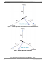
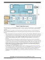
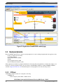
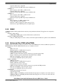
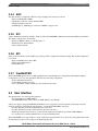
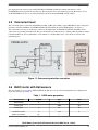
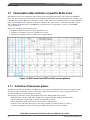
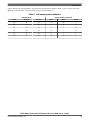
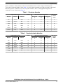
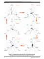
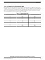
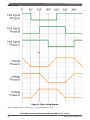
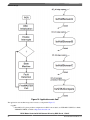
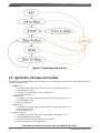
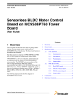
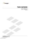
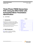
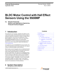
1
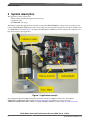
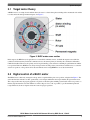
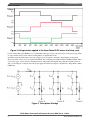
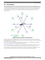
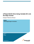
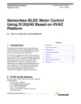
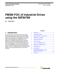
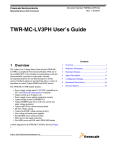
Freescale Semiconductor
Application Note
Document Number: AN4413
Rev. 0, 11/2011
BLDC Motor Control with Hall
Sensors Driven by DSC
using TWR-56F8257 and TWR-MC-LV3PH Boards
by:
Pavel Sustek
Systems Application Engineer, Microcontroller Solutions Group
Contents
1 Introduction
1
Introduction................................................................1
This application note describes the design of a three-phase
Brushless DC (BLDC) motor drive based on Freescale’s
MC56F8257 digital signal controller (DSC). The application
design incorporates the advantages of DSC peripherals for
motor control.
2
System description....................................................2
3
System concept..........................................................8
4
Software design.......................................................21
5
Summary and conclusions......................................27
6
References...............................................................27
BLDC motors are very popular in a wide array of applications.
Compared to a DC motor, the BLDC motor uses an electric
commutation, replacing the mechanical commutator and
making it more reliable than the DC motor. In BLDC motors,
rotor magnets generate the rotor’s magnetic flux, allowing
BLDC motors to achieve higher efficiency. Therefore, BLDC
motors may be used in high-end white goods such as
refrigerators, washing machines, dishwashers, etc., high-end
pumps, fans, and other appliances that require high reliability
and efficiency.
The concept of the application is to create a speed-closed loop
BLDC driver using a Hall position sensor. It serves as an
example of a BLDC motor control system design using one of
the latest member of Freescale DSCs. It also illustrates an
intelligible implementation of a BLDC control technique using
DSC features.
This application note also includes basic motor theory, system
design concept, hardware implementation, and DSC software
design, including the FreeMASTER visualization tool.
© 2011 Freescale Semiconductor, Inc.
System description
2 System description
This application consists of three parts:
• This document describing the application and its usage
• Application codee
• FreeMASTER control page
The hardware used in this application note is based on a three-phase BLDC/PMSM low-voltage motor control drive board
tower module TWR-MC-LV3PH, that provides a broad solution for testing and developing low-power drives and demos and
on a TWR-56F8257 board. See Figure 1. It demonstrates MC56F8257 and MC33937 devices and provides a hardware tool to
help develop motor control application.
Figure 1. Application concept
See a detailed description including the hardware specification in the User Manual for Freescale’s Tower Board
TWR-56F8257, TWR56F8257UM, available at http://www.freescale.com and the low voltage power stage
TWRMCLV3PHUM in TWR-MC-LV3PH User’s Guide, TWRMCLV3PHUG, available at http://www.freescale.com.
BLDC Motor Control with Hall Sensors Driven by DSC, Rev. 0, 11/2011
2
Freescale Semiconductor, Inc.
System description
2.1 Target motor theory
A BLDC motor is a rotating electric machine where the stator is a classic three-phase winding with concentrated coils and the
rotor has surface-mounted permanent magnets. See Figure 2.
Figure 2. BLDC motor cross section
In this respect, the BLDC motor is equivalent to a reversed DC commutator motor, in which the magnet rotates while the
conductors remain stationary. In the DC commutator motor, the current polarity is altered by the commutator and brushes.
Unlike the brushless DC motor, the polarity reversal is performed by power transistors switching in synchronization with the
rotor position. Therefore, BLDC motors always incorporate the external position sensors known as Hall sensors, to sense the
actual rotor position, or the position can be detected without sensors using BEMF zero cross detection method.
2.2 Digital control of a BLDC motor
The BLDC motor is driven by rectangular voltage strokes coupled with the given rotor position, as depicted in Figure 3. The
stator flux interacts with the rotor flux, generated by a rotor magnet and defines the torque and thus, the speed of the motor.
The voltage strokes must be properly applied to two phases of the three-phase winding system based on the rotor position, so
that the angle between the stator flux and the rotor flux is kept as close to 90° as possible, to get the maximum generated
torque. Therefore, the motor requires electronic control for proper operation.
BLDC Motor Control with Hall Sensors Driven by DSC, Rev. 0, 11/2011
Freescale Semiconductor, Inc.
3
System description
Figure 3. Voltage strokes applied to the three-Phase BLDC motor at full duty cycle
For the common three-phase BLDC motor, a standard three-phase power stage is used. See Figure 4. The power stage utilizes
six power transistors that operate either in an independent or complementary mode.
In both the modes, the three-phase power stage energizes two motor phases concurrently. The third phase is unpowered.
Thus, six possible voltage vectors are applied to the BLDC motor using the pulse-width modulation (PWM) technique. There
are two basic types of power transistor switching schemes: independent and complementary. Both the switching modes are
able to work in bipolar or unipolar mode. The present application utilizes the unipolar complementary / independent combine
PWM mode.
Figure 4. Three-phase H-bridge
BLDC Motor Control with Hall Sensors Driven by DSC, Rev. 0, 11/2011
4
Freescale Semiconductor, Inc.
System description
2.3 Commutation
Commutation provides the creation of a rotational field. As mentioned earlier, for proper operation of a BLDC motor, it is
necessary to keep the angle between the stator and rotor flux as close to 90° as possible. Total six possible stator flux vectors
can be obtained with a six-step control. The stator flux vector must be changed at specific rotor positions, which are usually
sensed by the Hall sensors. The Hall sensors generate three signals that also consist of six states. Each of the Hall sensors’
states correspond to a certain stator flux vector. All the Hall sensors states, with corresponding stator flux vectors, are
illustrated in Figure 5.
Figure 5. Stator flux vectors at six-step control
The next two figures depict the commutation process. The actual rotor position in Figure 6 corresponds to the Hall sensors
state ABC[110]. Phase A is connected to the positive DC-bus voltage by transistor Q1; Phase B is connected to the ground by
transistor Q6, and Phase C is unpowered.
As soon as the rotor reaches a certain position, the Hall sensors state changes its value from ABC[110] to ABC[100]. See
Figure 7 A new voltage pattern is selected and applied to the BLDC motor.
As shown in Figure 6 and Figure 7, it is difficult to keep the angle between the rotor flux and the stator flux precisely at 90°
in a six-step control technique, while using the six-step control technique. The actual angle varies from 60° to 120°.
The commutation process is repeated per each 60 electrical degrees and is critical to change the switching pattern as fast as
possible after a Hall sensor edge is detected. Any deviation causes torque ripples, resulting in speed variation.
BLDC Motor Control with Hall Sensors Driven by DSC, Rev. 0, 11/2011
Freescale Semiconductor, Inc.
5
System description
Figure 6. Situation right before commutation (counterclockwise motion)
Figure 7. Situation right after commutation
BLDC Motor Control with Hall Sensors Driven by DSC, Rev. 0, 11/2011
6
Freescale Semiconductor, Inc.
System description
2.4 Speed control
The commutation ensures the proper rotor rotation of the BLDC motor, while the motor speed depends only on the amplitude
of the applied voltage, which is adjusted using the PWM technique. The required speed is controlled by a speed controller,
which is implemented as a conventional proportional-integral (PI) controller. See Figure 8. The difference between the actual
and required speeds is input to the PI controller which then, based on this difference, controls the duty cycle of the PWM
pulses corresponding to the voltage amplitude required to maintain the desired speed.
Figure 8. Speed controller
The speed controller calculates the PI algorithm. After the transformation into a discrete time domain using an integral
approximation with the Backward Euler method, the numerical PI controller can be calculated using the following equations:
where:
e(k)
=
Input error in step k
w(k)
=
Desired value in step k
m(k)
=
Measured value in step k
u(k)
=
Controller output in step k
upk
=
Proportional output portion in step k
uIk
=
Integral output portion in step k
uI(k-1)
=
Integral output portion in step k-1
TI
=
Integral time constant
T
=
Sampling time
KC
=
Controller gain
BLDC Motor Control with Hall Sensors Driven by DSC, Rev. 0, 11/2011
Freescale Semiconductor, Inc.
7
System concept
3 System concept
3.1 System outline
The system is designed to drive a three-phase BLDC motor. The application meets the following performance specifications:
• Speed control of a BLDC motor using Hall sensors
• Targeted at TWR-56F8257 MCU Board, TWR-MC-LV3PH Low Voltage Power Stage, TWR-ELEV, and LINIX
45ZWN24-40 BLDC motor
• Features of the control technique:
• Low-voltage BLDC motor control with speed-closed loop
• Bidirectional rotation
• Two-quadrant operation
• Capability to start from any motor position without rotor alignment
• Minimum speed of 300 rpm
• Maximum speed of 4000 rpm, limited by power supply
• Manual interface with Up/Down push button control and LED indication
• FreeMASTER control interface with speed set-up feature
• FreeMASTER monitor
• FreeMASTER Graphical Control Page to set the required speed, actual motor speed, start/stop status, and fault
status
• FreeMASTER Speed Control Scope to observe the required, ramp, and actual speeds, and applied voltage
• DC-bus overcurrent, overvoltage, and undervoltage fault protection
3.2 Application description
A standard system concept is chosen for the motor control function. See Figure 9. The system incorporates the following
hardware:
• TWR-56F8257 board
• TWR-MC-LV3PH board
• Tower Elevator
• LINIX 45ZWN24-40 BLDC motor with Hall sensors
• Power Supply 24 V DC, 3.7 A
For detailed description of a hardware configuration, see TWR-MC-LV3PH User’s Guide, TWRMCLV3PHUG, available at
http://www.freescale.com.
The DSC MC56F8257 runs the main control algorithm. The three-phase PWM output signals for a three-phase inverter are
generated according to feedback signals from Hall sensors and input variables. See Figure 9.
BLDC Motor Control with Hall Sensors Driven by DSC, Rev. 0, 11/2011
8
Freescale Semiconductor, Inc.
System concept
Figure 9. Application concept
The required speed of a connected BLDC motor might be set either by using the onboard push buttons or, the FreeMASTER
control page. The detection of three main faults, namely, overvoltage, undervoltage, and overcurrent, is implemented in the
application.
The main application state machine runs in the background loop together with a fault detection routine, manual interface
processing and FreeMASTER polling function calling. The application concept can be understood by means of three main
functions:
• Speed controller function: The speed controller function is called every 10 ms using Timer 3 ISR. Hall sensor edges are
captured using Timers 0-2 and commutation function is called accordingly. The comparison between the required speed
command and the actual speed calculated from Hall sensor signals generates speed error. The speed error enters the PI
speed controller that generates a voltage amplitude. The PWM generation process calculates a system of three-phase
voltages of required amplitude including dead time, and finally the three-phase PWM motor control signals are
generated.
• Fault detection and protection: The application accommodates fault protection. DC-bus current is evaluated by the
predriver MC33397 and in case, any fault like overcurrent, desaturation, or undervoltage, etc., is detected, a fault signal
is generated. After a fault is detected, the predriver immediately disables the PWM output. In case of undervoltage, the
predriver enters the fault state as well. If any of the above-mentioned faults occur, the motor control PWM outputs are
disabled in order to protect the drive. When the application is in the Stop state, no voltage is applied to the motor
windings. When the application is in the Run state, the motor speed can be controlled either by the Up/Down buttons
on the board, or by the FreeMASTER software on the PC.
• FreeMASTER software: The FreeMASTER software also displays a control page, as shown in Figure 10, real-time
values of application variables, and their time behaviour using scopes. FreeMASTER software was designed to provide
an application-debugging, diagnostic, and demonstration tool for the development of algorithms and applications. It
runs on a PC connected to the TWR-56F8257 via a USB cable. A small program resident in the microprocessor
communicates with the FreeMASTER software to return status information to the PC and process control information
from the PC.
.
BLDC Motor Control with Hall Sensors Driven by DSC, Rev. 0, 11/2011
Freescale Semiconductor, Inc.
9
System concept
Figure 10. Application FreeMASTER control page
3.3 Used peripherals
The present BLDC application uses only the essential peripherals for control technique implemented in the application code:
• Analog-to-digital converter (ADC)
• Quad timer (QTimer)
• Pulse-width modulation (PWM)
• XBAR
• Serial peripheral interface (SPI)
• Serial communication interface (SCI)
Other peripherals are disabled. A peripheral initialization is done using Freescale QuickStart tool which offers simple-to-use
interface for all device peripheral settings. For more details, read TWR-MC-LV3PH User’s Guide, TWRMCLV3PHUG,
available at http://www.freescale.com. Detailed descriptions of used peripherals are in the following sections.
3.3.1 QTimer
A MC56F8257 QTimer module A is configured as following:
• QTIMER_A0:
• Runs at frequency 468.75 kHz, or, IPB clock/128
BLDC Motor Control with Hall Sensors Driven by DSC, Rev. 0, 11/2011
10
Freescale Semiconductor, Inc.
System concept
• Captures both the edges of input T0
• Generates the input-edge ISR with priority 0, IsrHallSensorA
• QTIMER_A1:
• Runs at frequency 468.75 kHz, or, IPB clock/128
• Captures both the edges of input T1
• Generates the input-edge ISR with priority 0, IsrHallSensorB
• QTIMER_A2:
• Runs at frequency 468.75 kHz, or, IPB clock/128
• Captures both the edges of input T2
• Generates the input-edge ISR with priority 0, IsrHallSensorC
• QTIMER_A3:
• Runs at frequency 3.75 MHz, or, IPB clock/16
• Counts until compare and reinitializes
• Generates a 10 ms loop using the compare value of 37,499
• Generates the compare ISR with priority 2, IsrQT3Compare
3.3.2 XBAR
An XBAR peripheral enables peripheral interconnectivity using 30 dedicated channels. The application is configured as
following:
• Channel 6: ADCA Trigger
• PWM0_TRIG_COMB signal is used for ADC hardware synchronization.
• Channel 21: PWM module FAULT0
• GPIO_C2 / GPIO_E4 pins are used to connect external fault signal from MC33937 predriver to the ePWM fault.
3.3.3 Enhanced Flex PWM (eFlexPWM)
ePWM is a dedicated peripheral enabling the generation of three-phase PWM signals connected via MC33937 predriver to
MOSFET H-bridge. The three PWM submodules used, are configured as follows:
• PWM_0
• IPBus clock source
• Running frequency of 16 kHz with 62.5 µs period
• Modulo 3750 with 11-bit resolution
• Complementary mode with 1 µs deadtime
• PWM reload and synchronization signals generated every period from this module
• Trigger 4 enabled to provide synchronization with ADC module via XBAR
• High-side switch PWM_A output in negative polarity
• Low-side switch PWM_B output in positive polarity
• PWM_1 and PWM_2
• PWM_0 clock source
• Running frequency of 16 kHz with 62.5 µs period
• Modulo 3750 with 11-bit resolution
• Complementary mode with 1 µs deadtime
• PWM reload and synchronization signals generated every period from PWM_0 module
• High-side switch PWM_A output in negative polarity
• Low-side switch PWM_B output in positive polarity
• PWM FAULT
• Fault 0 signal with high-level detection
• Automatic fault clearing
• PWM_A, PWM1_A, and PWM2_A channels disabled and output pins set to high-level, if a fault is detected.
• PWM0_B, PWM1_B, and PWM2_B channels disabled and output pins set to low-level, if a fault is detected.
• Fault input filter disabled
BLDC Motor Control with Hall Sensors Driven by DSC, Rev. 0, 11/2011
Freescale Semiconductor, Inc.
11
System concept
3.3.4 ADC
The ADC module is configured for DC-bus voltage sampling and conversion as follows:
• Input clock IPBus/10 = 6 MHz
• Sample 0 set to DC-bus voltage channel ANB0
• Triggered parallel scan mode
• SYNC0 input, or, PWM trigger connected via XBAR, as trigger source
3.3.5 SCI
Serial communication interface channel 1 (SCI1) is used for FreeMASTER communication between the MCU board and PC.
The module configuration is as following:
• Baud rate 9600 bit/s; Divisor = 390, Fine tune = 5
• Enabled receiver and transmitter
• Other setting by default
3.3.6 SPI
SPI is a four-wire interface used for MC33937 3-phase predriver configuration and status reading. The module configuration
is as follows:
• Input clock IPBUs/128 = 468.75 kHz
• Falling-edge SCLK polarity
• Master SPI mode
3.3.7 FreeMASTER
The FreeMASTER application is not a DSC peripheral but its embedded driver is configured from QuickStart Graphical
Configuration tool as one of the peripherals. The driver has following configuration:
• SCI1 communication interface
• Polling Mode interrupt processing
• Up to a maximum of eight variables as per the enabled Scope feature
3.4 User interface
The application has one of the following interfaces:
• Up / Down buttons on TWR-56F8257
• FreeMASTER running on PC connected to TWR-56F8257 via USB cable
After power supply is plugged in TWR-MC-LV3PH, the motor is prepared to run. The required speed setting and on/off
functions can be processed either through the buttons, or from the FreeMASTER control page:
• Pressing SW1 button sets the clockwise direction of the motor.
• Pressing SW2 button sets the counterclockwise direction of the motor.
• Further pressing the buttons increases or decreases the required speed within the speed limit -4800–4800 rpm.
• To stop the motor, both SW1 and SW2 have to be pressed simultaneously.
The FreeMASTER control page enables to set the required speed and switch the motor on/off. Also, through the Demo mode,
the required speed value is set according to the defined speed profile.
BLDC Motor Control with Hall Sensors Driven by DSC, Rev. 0, 11/2011
12
Freescale Semiconductor, Inc.
System concept
If an application fault is detected, the red FAULT LED on TWR-MC-LV3PH is lit and the fault indicator on the
FreeMASTER control page indicates the fault state. The actual fault can be cleared either by pressing Reset button, in case
the FreeMASTER is not used, or, by setting Clear Fault variable in the FreeMASTER variable window.
3.5 Overcurrent level
The overcurrent signal is connected via TWR-Elevator IRQ_A (B62) pin to GPIO_C2 pin of MC56F8257 device. This pin is
internally connected via XBAR to the PWM FAULT0 signal that handles the fault by PWM hardware. See Figure 11.
The overcurrent level can be set in the range of 0-8 A by the trimmer R37 on TWR-MC-LV3PH. The maximum current
value can be set by turning the trimmer left. The user can find the level when the motor is running while the trimmer is turned
left until red LED is lit. It is recommended to set the trimmer to somewhat higher level, so that the motor can run at the
maximum speed.
Figure 11. Overcurrent protection connection
3.6 BLDC motor with Hall sensors
The enclosed motor is a low-voltage LINIX 45ZWN24-40. The motor can be controlled using Hall sensor techniques. The
motor characteristics are in Table 1.
Table 1. LINIX motor parameters
Characteristic
Symbol
Type
Units
Rated voltage
Vt
24
V
4000
rpm
Rated speed
Rated power
p
40
W
Continuous current
Ics
2.34
A
Number of pole pairs
pp
2
BLDC Motor Control with Hall Sensors Driven by DSC, Rev. 0, 11/2011
Freescale Semiconductor, Inc.
13
System concept
3.7 Commutation table definition of specific BLDC motor
The definition of the correct commutation table is the key point of the application porting for the customer-specific BLDC
motor. The aim of the process is the definition of the commutation pattern that is generated at the MCU ports according to the
sensed Hall sensor pattern. Hall sensors detect the rotor flux, so their actual state is not influenced by stator current. The Hall
effect outputs in BLDC motors divide the electrical revolution into three equal sections of 120° electrical. In this so called
120° configuration, the Hall states 111 and 000 never occur. Hall sensors are aligned phase-to-phase to the back-EMF
voltage. See Figure 12.
The process of definition has the following steps:
1. Definition of Hall sensor pattern for each commutation sector
2. Definition of commutation vector for each Hall sensor pattern
3. Definition of commutation table according to the s/w implementation
Figure 12. BLDC motor back-EMF and Hall sensors patterns
3.7.1 Definition of Hall sensor pattern
The Hall sensor pattern corresponding to the BLDC motor sector needs to be defined. This can be done by supplying all the
three phases with a combination of positive and negative voltage that causes the motor to move to the given sector and
observing the Hall sensor signals when the motor settles.
The following steps describe a simple method which can be used to define the Hall sensor pattern:
• Mark all the motor phases as A,B, and C and Hall sensor outputs as H1, H2, and H3, in the desired order.
• Set the current limit of power supply to 20-30% of nominal motor current.
• Choose the direction of the motor rotation to be clockwise / counterclockwise.
• Connect one out of the three motor phases to the positive terminal as shown in the first row of Table 2.
• Connect the remaining two phases to the negative terminal. All the phases are always supplied.
BLDC Motor Control with Hall Sensors Driven by DSC, Rev. 0, 11/2011
14
Freescale Semiconductor, Inc.
System concept
Table 2 illustrates the required phases to be powered for the desired sector and the example of sensor output for the given
BLDC motor. The sectors I - VI correspond to the sectors shown in Figure 13.
Table 2. Hall sensor pattern definition
Powered phase
Sensor output of the motor
Phase
Phase B
Phase C
Hall C
Hall B
Hall A
+U
-U
-U
1
0
1
+U
+U
-U
1
0
0
-U
+U
-U
1
1
0
-U
+U
+U
0
1
0
-U
-U
+U
0
1
1
+U
-U
+U
0
0
1
BLDC Motor Control with Hall Sensors Driven by DSC, Rev. 0, 11/2011
Freescale Semiconductor, Inc.
15
System concept
Figure 13. Commutation sector definition
3.7.2 Definition of commutation vector
When the Hall sensor patterns are defined, the corresponding commutation vectors can also be defined. For each of the
sectors I-VI, the corresponding commutation vector A-F and Hall sensor pattern are defined. Table 3 shows the vectors for
clockwise direction of rotation that ensures the variation of real angle from 60° to 120°. See Commutation. The Hall sensor
BLDC Motor Control with Hall Sensors Driven by DSC, Rev. 0, 11/2011
16
Freescale Semiconductor, Inc.
System concept
pattern, considered as a binary number, results in a decimal number from 1 to 6. For example, 101 in binary form
corresponds to the decimal number 5. From Table 3, it can be seen that commutation vector B corresponds to the decimal
Hall sensor pattern 4, commutation vector A corresponds to number 5, and so on. The graphical interpretation of
commutation vectors is illustrated in Figure 14.
Table 3. Clockwise direction
Commutation vector
Vector
Phase A
Phase B
Phase C
NC
+VDCB
-VDCB
-VDCB
+VDCB
-VDCB
Hall sensor pattern definition
Hall sensor
pattern
result
Hall Sensor
C
Hall Sensor
B
Hall Sensor
A
A
1
0
1
5
NC
B
1
0
0
4
NC
+VDCB
C
1
1
0
6
NC
-VDCB
+VDCB
D
0
1
0
3
+VDCB
-VDCB
NC
E
0
1
1
2
+VDCB
NC
-VDCB
F
0
0
1
1
Table 4. Counterclockwise direction
Commutation vector
Vector
Phase A
Phase B
Phase C
NC
-VDCB
+VDCB
-VDCB
NC
-VDCB
Hall sensor pattern definition
Hall sensor
pattern
result
Hall Sensor
C
Hall Sensor
B
Hall Sensor
A
D
1
0
1
5
+VDCB
C
0
0
1
1
+VDCB
NC
B
0
1
1
3
NC
+VDCB
-VDCB
A
0
1
0
2
+VDCB
NC
-VDCB
F
1
1
0
6
+VDCB
-VDCB
NC
E
1
0
0
4
BLDC Motor Control with Hall Sensors Driven by DSC, Rev. 0, 11/2011
Freescale Semiconductor, Inc.
17
System concept
Figure 14. Commutation vector definition for clockwise direction
BLDC Motor Control with Hall Sensors Driven by DSC, Rev. 0, 11/2011
18
Freescale Semiconductor, Inc.
System concept
3.7.3 Definition of commutation table
In the application software, the commutation vectors are defined as entries 0-7 in Table 5. Any Hall sensor pattern provides
the pointer to the table of commutation vectors. For this example, Table 5 shall be used. The Hall sensor patterns 0 [000] and
7 [111] indicate a fault because such combinations are not available during the normal operation. Such states can be caused
either by a disconnected Hall sensor interface, or through malfunctioning. In these cases, the output channels are switched
off, or the output signals are put into a safe state, in order to protect the drive.
Table 5. Commutation table
Hall sensor pattern result
Commutation vector CW
Commutation vector CCW
0
OFF
OFF
1
F
C
2
D
A
3
E
B
4
B
E
5
A
D
6
C
F
7
OFF
OFF
BLDC Motor Control with Hall Sensors Driven by DSC, Rev. 0, 11/2011
Freescale Semiconductor, Inc.
19
System concept
Figure 15. Motor timing diagram
The motor timing diagram, shown in Figure 15 can be summarized as follows:
BLDC Motor Control with Hall Sensors Driven by DSC, Rev. 0, 11/2011
20
Freescale Semiconductor, Inc.
Software design
• For clockwise direction: Read the motor timing diagram from to left to right. The Hall signal Phase B low-high
transition comes at 120° electrical, depicted as red dotted line. The PWM Phase B is turned off and Phase C is on with
positive duty cycle during this transition.
• For counterclockwise direction: Read the motor timing diagram from left to right and the polarity of phases will be
swapped. Therefore, if Phase A is in negative polarity from 60° to 180° for the clockwise direction, it will be in
positive polarity for the counterclockwise direction.
4 Software design
This section describes the software design of the BLDC motor drive application. The system processing is interrupt driven
with the application state machine running in background. The software is described in terms of the following:
• Main Software Flow Chart
• Application Interrupts
4.1 Main software flow chart
After a reset, the application performs the following routines and enters the endless (main()) loop.
• PeripheralCoreInit
• Initialization function calling of peripherals used in the application
• FMSTR_Init
• FreeMASTER embedded driver initialization based on setting in the GCT panel
• archEnableInt
• Global interrupt flag enabled
The application background main() loop incorporates the state machine, fault detection, and FreeMASTER polling function
calling. See Figure 16.
BLDC Motor Control with Hall Sensors Driven by DSC, Rev. 0, 11/2011
Freescale Semiconductor, Inc.
21
Software design
Figure 16. Application main flow
The application state machine incorporates four states, as depicted in Figure 17 :
• AppInit:
• Runs MC33937 3-phase predriver configuration via SPI. For more details, see TWR-MC-LV3PH User’s Guide,
TWRMCLV3PHUG, available at http://www.freescale.com
BLDC Motor Control with Hall Sensors Driven by DSC, Rev. 0, 11/2011
22
Freescale Semiconductor, Inc.
Software design
• Sets speed controller constants
• Reads DC-bus voltage
• AppStop:
• Checks whether the nonzero speed command is set either from FreeMASTER or, by pressing push buttons to set
motor rotation direction.
• AppRun:
• Increases or decreases the required speed based on the state of push buttons
• Allows motor reversing
• Updates the PWM register
• AppError:
• Disables PWM outputs
Transition between the main states is performed using the following four transient states:
• AppInitToStop:
• Goes to the Stop state
• AppStopToRun:
• Sets the motor direction
• Sets the initialized output vector
• Updates the PWM register
• Enables PWM outputs
• AppRunToStop:
• Enters when the main switch is turned off in the FreeMASTER control page, or both the push buttons are pressed
simultaneously
• Clears variables
• Disables PWM
• AppErrorToStop:
• Clears variables
• Tests fault clear variable
• Turns fault LED off
BLDC Motor Control with Hall Sensors Driven by DSC, Rev. 0, 11/2011
Freescale Semiconductor, Inc.
23
Software design
Figure 17. Application state machine
4.2 Application interrupts and routines
Four interrupt service routines (ISR) execute the 10 ms control loop and capture three Hall sensor edges. Tasks performed in
each ISR are described below:
• IsrHallSensorA:
• Uses QTimer_A0 module, enables the Input Capture interrupt with priority level 2
• Calls commutation routine
• Calculates the period between two edges of Hall sensor A
• Clears the Capture flag
• IsrHallSensorB:
• Uses QTimer_A1 module, enables the Input Capture interrupt with priority level 2
• Calls commutation routine
• Clears the Capture flag
• IsrHallSensorC:
• Uses QTimer_A2 module, enables the Input Capture interrupt with priority level 2
• Calls commutation routine
• Clears the Capture flag
• IsrQTA3Compare:
• Uses QTimer_A3 module, enables the Compare interrupt with priority level 0
• Calls CheckManualInterface routine
• Calculates the actual speed value based on motor direction
• Performs ramp function of the required speed
BLDC Motor Control with Hall Sensors Driven by DSC, Rev. 0, 11/2011
24
Freescale Semiconductor, Inc.
Software design
•
•
•
•
Calculates output duty cycle utilizing PI speed controller
Clears the Compare flag
Reads status registers of three-phase predriver MC33937
Reads the value of DC-Bus voltage
Apart from state machine and interrupt service routines, the application includes following functions:
• CheckManualInterface:
• Runs in 10 ms loop
• Checks status of Up / Down push buttons
• Sets status bits accordingly
• FaultDetection:
• Runs in background loop
• Checks the DC-bus voltage value for overvoltage and undervoltage fault
• Checks PWM_FAULT0 flag connected to MC33937 for overcurrent detection
• Turns fault LED on, if a fault is detected
• Sets Error state
• CommutationHS:
• Enters from all the three Hall sensor capture ISRs
• Decodes Hall sensor input state
• Negates the Hall sensor state for opposite motor direction
• Updates the Mask register based on the Hall sensor state
• Sets software control in the Deadtime source register to a PWM pair based on Hall sensor state
• Applies the Force event to change the combination of switch states
4.3 Commutation process
The motor commutation is processed once a Hall sensor edge is captured. The new switching state is set according to the
commutation table defined in application constants commutationTableMask[] and commutationTableSWC[] based on actual
Hall sensor status. Every 60° electrical is called the CommutationHS routine where:
• One motor phase is turned off.
• The second phase with positive polarity is used for PWM complementary signal generation.
• The last phase with negative polarity is set to the state where the top transistor is turned off and the bottom transistor is
turned on using the PWM Deadtime source register.
The immediate change of output PWM waveform enables the Force event which is generated at the end of the commutation
routine.
The PWM technique where one pair of transistors work in a complementary mode and the other in an unipolar mode is called
Combined Complementary / Independent Unipolar PWM switching. It is the best choice for MOSFET H-Bridge which
eliminates losses in freewheeling diodes utilizing a MOSFET as a diode without threshold voltage. See Figure 18. The figure
shows the connections of a BLDC motor without a phase which is turned off in a commutation period. Transistors Q1 and Q2
run in complementary mode whereas Q3 is turned off and Q4 is turned on during this period. Following commutation, the
transistor pairs will be set to a new state according to the predefined commutation table.
BLDC Motor Control with Hall Sensors Driven by DSC, Rev. 0, 11/2011
Freescale Semiconductor, Inc.
25
Software design
Figure 18. PWM switching
4.4 Speed processing
The first input value of the speed processing is set either by the Up / Down push buttons, or FreeMASTER control page as
the f16SpeedCommand variable. This variable is passed to f16SpeedRequired based on the motor direction and minimal
speed. The ramp function calculates output f16SpeedRamp using the input variable f16SpeedRequired. The variable
f16SpeedRamp enters the speed controller as a desired value.
The second input value is calculated using a period between the two edges of Hall sensor A. The output of the formula is the
actual speed value, f16SpeedActual, which enters the speed controller.
The speed controller is implemented as a PI controller library function in parallel form (GFLIB_ControllerPIp). The output of
the controller is a duty cycle which is put to the PWM value registers. The speed process is shown in Figure 19.
Figure 19. Speed processing
BLDC Motor Control with Hall Sensors Driven by DSC, Rev. 0, 11/2011
26
Freescale Semiconductor, Inc.
Summary and conclusions
4.4.1 Speed constants and scaling
All speed constants are related to the maximum value defined in N_MAX = 5000 rpm. Calculations are done in the factional
format 1.15 in range from -1 to 1.
The actual speed value is calculated using a period between Hall sensor edges and a scale constant which enables time value
conversion to speed value. The actual speed is calculated using the following equation:
where PERIOD_TO_SPEED is calculated as following:
where for LINIX 45ZVN24-40 BLDC motor:
• IPBCLK = 60,000,000 Hz
• N_MAX = 5000 rpm
• QT_PRESCLR = 128
• POLE_PAIRS = 2
The constant value PERIOD_TO_SPEED, mentioned above, expresses that for theoretical maximum measurable speed of
5,000 rpm, the period is 1406 clocks of QTimer A3. For lower speeds, the numbers of clocks are higher which suggests that
the variable f16SpeedActual is always in the range from -1 to 1. The period is measured between the falling and rising edges
of a Hall sensor signal and equals the half period of an electric revolution. To get the full electrical period, the measured
clock number has to be multiplied by 2. This is included in the PERIOD_TO_SPEED constant.
This range corresponds to mechanical speed range -5,000 to 5000 rpm.
The minimal measurable speed is limited to 32,767 clocks which correspond to a speed of 214 rpm wherein the application is
limited to 250 rpm expressed by the constant N_MIN.
Speed PI controller constants are set in AppInit() routine. Constant values are tuned using the FreeMASTER control page.
5 Summary and conclusions
This application note provides the user with a description of the demo application BLDC motor with speed-closed loop using
Hall sensors and guides how to measure and implement a commutation table for a BLDC motor with Hall sensors.
The application source code is written with aspect of simplicity and legibility to enable rapid code porting to any DSC
member.
6 References
• TWR-MC-LV3PH User’s Guide, TWRMCLV3PHUG, available at http://www.freescale.com
• User Manual for Freescale’s Tower Board TWR-56F8257, TWR56F8257UM, available at http://www.freescale.com
• Three-Phase BLDC Motor Control Using MC56F8257 User’s Guide, BLDC56F8257UG available at http://
www.freescale.com
• DSP56800E QuickStart User’s Manual, available at http://www.freescale.com
• MC33937, Three Phase Field Effect Transistor Pre-driver, available at http://www.freescale.com
BLDC Motor Control with Hall Sensors Driven by DSC, Rev. 0, 11/2011
Freescale Semiconductor, Inc.
27
How to Reach Us:
Home Page:
www.freescale.com
Web Support:
http://www.freescale.com/support
USA/Europe or Locations Not Listed:
Freescale Semiconductor
Technical Information Center, EL516
2100 East Elliot Road
Tempe, Arizona 85284
+1-800-521-6274 or +1-480-768-2130
www.freescale.com/support
Europe, Middle East, and Africa:
Freescale Halbleiter Deutschland GmbH
Technical Information Center
Schatzbogen 7
81829 Muenchen, Germany
+44 1296 380 456 (English)
+46 8 52200080 (English)
+49 89 92103 559 (German)
+33 1 69 35 48 48 (French)
www.freescale.com/support
Japan:
Freescale Semiconductor Japan Ltd.
Headquarters
ARCO Tower 15F
1-8-1, Shimo-Meguro, Meguro-ku,
Tokyo 153-0064
Japan
0120 191014 or +81 3 5437 9125
[email protected]
Asia/Pacific:
Freescale Semiconductor China Ltd.
Exchange Building 23F
No. 118 Jianguo Road
Chaoyang District
Beijing 100022
China
+86 10 5879 8000
[email protected]
For Literature Requests Only:
Freescale Semiconductor Literature Distribution Center
1-800-441-2447 or +1-303-675-2140
Fax: +1-303-675-2150
[email protected]
Document Number: AN4413
Rev. 0, 11/2011
Information in this document is provided solely to enable system and software
implementers to use Freescale Semiconductors products. There are no express or implied
copyright licenses granted hereunder to design or fabricate any integrated circuits or
integrated circuits based on the information in this document.
Freescale Semiconductor reserves the right to make changes without further notice to any
products herein. Freescale Semiconductor makes no warranty, representation, or
guarantee regarding the suitability of its products for any particular purpose, nor does
Freescale Semiconductor assume any liability arising out of the application or use of any
product or circuit, and specifically disclaims any liability, including without limitation
consequential or incidental damages. "Typical" parameters that may be provided in
Freescale Semiconductor data sheets and/or specifications can and do vary in different
applications and actual performance may vary over time. All operating parameters,
including "Typicals", must be validated for each customer application by customer's
technical experts. Freescale Semiconductor does not convey any license under its patent
rights nor the rights of others. Freescale Semiconductor products are not designed,
intended, or authorized for use as components in systems intended for surgical implant
into the body, or other applications intended to support or sustain life, or for any other
application in which failure of the Freescale Semiconductor product could create a
situation where personal injury or death may occur. Should Buyer purchase or use
Freescale Semiconductor products for any such unintended or unauthorized application,
Buyer shall indemnify Freescale Semiconductor and its officers, employees, subsidiaries,
affiliates, and distributors harmless against all claims, costs, damages, and expenses, and
reasonable attorney fees arising out of, directly or indirectly, any claim of personal injury
or death associated with such unintended or unauthorized use, even if such claims alleges
that Freescale Semiconductor was negligent regarding the design or manufacture of
the part.
RoHS-compliant and/or Pb-free versions of Freescale products have the functionality and
electrical characteristics as their non-RoHS-complaint and/or non-Pb-free counterparts.
For further information, see http://www.freescale.com or contact your Freescale
sales representative.
For information on Freescale's Environmental Products program, go to
http://www.freescale.com/epp.
Freescale™ and the Freescale logo are trademarks of Freescale Semiconductor, Inc.
All other product or service names are the property of their respective owners.
© 2011 Freescale Semiconductor, Inc.