1
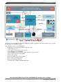
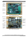
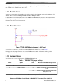
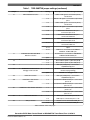
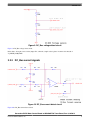
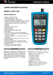
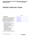
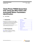
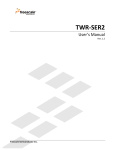
Freescale Semiconductor
User Guide
Document Number:S08PT60UG
Rev. 0, 02/2013
Sensorless BLDC Motor Control
Based on MC9S08PT60 Tower
Board
User Guide
Contents
1 Overview
1
Overview....................................................................1
This user guide describes the basic steps for getting started
with the sensorless BLDC motor control based on
MC9S08PT60 Tower Board demo. The basic board function is
described in this document.
2
Demo boards..............................................................3
3
Hardware feature.......................................................5
3.1
TWR-S08PT60...............................................5
The whole system is composed of TWR-S08PT60 and TWRMC-LV3PH (3-phase low voltage motor control board).
3.1.1
System power..................................5
3.1.2
Push buttons.....................................6
TWR-S08PT60 is a low-cost evaluation, demonstration and
development board that features the 8-bit MC9S08PT60
microcontroller. The MC9S08P series are members of the
low-cost, high-performance S08 family of 8-bit
microcontroller units (MCUs). The MC9S08PT60 has up to 60
KB flash memory, 256 byte EEPROM, 4 KB RAM, and has a
large set of peripherals including timers (3FTMs, 2 MTIMs), 3
SCIs (UARTs), 2 SPIs, I2C, ADC, ACMP, KBI, TSI, and
others.
3.1.3
Potentiometer...................................6
3.1.4
Jumper tables...................................6
The following figure presents the block diagram of
MC9S08PT60 Tower board.
© 2013 Freescale Semiconductor, Inc.
3.2
TWR-MC-LV3PH..........................................8
3.2.1
Back EMF signals............................8
3.2.2
DC_Bus voltage signals...................8
3.2.3
DC_Bus current signals. ..................9
3.2.4
Jumper tables.................................10
4
Conclusions.............................................................10
5
Reference documents..............................................10
Overview
Figure 1. TWR-S08PT60 block diagram
The 3-phase Low Voltage Motor Control Board (TWR-MC-LV3PH) is a peripheral Tower System module. Figure 2 presents
the block diagram of TWR-MC-LV3PH.
Following are the features of the TWR-LV3PH.
• Power supply voltage input 12-24 V DC, extended up to 50 V.
• Output current up to 8 A
• Power supply reverse polarity protection circuitry
• 3-phase bridge inverter (6-MOSFETs)
• 3-phase MOSFET gate driver with over current and under voltage protection
• 3-phase and DC bus current-sensing shunts
• DC bus-voltage sensing
• 3-phase back-EMF voltage sensing circuitry
• Encode / hall sensor sensing circuitry
• Motor power and signal connectors
• User LED, power-on LED, and 6 PWM LED diodes
Sensorless BLDC Motor Control Based on MC9S08PT60 Tower Board, Rev. 0, 02/2013
2
Freescale Semiconductor, Inc.
Demo boards
Figure 2. TWR-MC-LV3PH block diagram
2 Demo boards
The following figures depict the TWR-S08PT60 and TWR-MC-LV3PH demo boards labelled with the different components.
Sensorless BLDC Motor Control Based on MC9S08PT60 Tower Board, Rev. 0, 02/2013
Freescale Semiconductor, Inc.
3
Demo boards
Figure 3. TWR-S08PT60 demo board
Figure 4. TWR-MC-LV3PH demo board
Sensorless BLDC Motor Control Based on MC9S08PT60 Tower Board, Rev. 0, 02/2013
4
Freescale Semiconductor, Inc.
Hardware feature
3 Hardware feature
3.1 TWR-S08PT60
3.1.1 System power
The TWR-S08PT60 can be powered by the OSBDM circuit Mini-B USB connector when running in standalone mode. When
assembled with the Tower System, the TWR-S08PT60 is powered by the Tower System Elevators. The mini-B USB
connector is no longer used as a power source and is only used for OSBDM debugging purposes.
When working in standalone mode, short pins 2 and 3 on J25 and J26 jumper blocks as the default setting. When working
with the Tower System, short pins 1 and 2 on both J25 and J26 jumper blocks, as shown in the following figure.
Figure 5. Power supply selection for standalone or Tower Elevator
The PT60 can be powered by 5 V or 3.3 V power supply which is configurable via jumper J27. To use 5 V power supply,
short pins 1 and 2 and to use 3.3 V power supply, short pins 2 and 3. See the following figure.
Figure 6. Power supply selection for 5 V or 3.3 V
Sensorless BLDC Motor Control Based on MC9S08PT60 Tower Board, Rev. 0, 02/2013
Freescale Semiconductor, Inc.
5
TWR-S08PT60
In this application, VDD_3V3_ELEV is selected as power supply according to TWR-MC-LV3PH’s configuration. So, short
pins 1 and pin 2 of J26, and short pins 2 and 3 of J27.
3.1.2 Push buttons
There are two general-purpose buttons which can be used to evaluate keyboard interrupts, and general switch inputs: SW2
and SW3. SW2 is connected to KBIP5 pin of PT60 and SW3 to KBIP4 pin of PT60.
In addition, there is a reset button (SW4) used to reset PT60 and a force BDM button (SW1) used to manually force PT60
into BDM upon power up or reset.
In this application, SW2 is used to increase speed.
3.1.3 Potentiometer
Figure 7. TWR-S08PT60 potentiometer to ADC input
A potentiometer is connected to the ADC input channel ADP0 through a jumper J7 as shown in Figure 7.
In this application, the jumper J7 must be open, because DC_Bus current sample AD channel is conflicting with it.
3.1.4 Jumper tables
The following table shows the jumper settings of TWR-S08PT60 demo board.
Table 1. TWR-S08PT60 jumper settings
Jumper
Option
Setting
Description of MC9S08PT60 signal routing
J1
UART2 selection
1–2
Connect RXD2 to OSBDM UART RX
J2
UART2 selection
1–2
Connect TXD2 to OSBDM UART TX
J3
ACMP1 Selection
1–2
ACMP1 is connected to Touch pad TWRPI pin18
of J8.
2–3
ACMP1 is optionally connected to motor control
TWRPI pin15 of J10.
1–2
U1(ICL3232) pin 9 and pin 10 are shorted.
J4
UART transceiver loop
Table continues on the next page...
Sensorless BLDC Motor Control Based on MC9S08PT60 Tower Board, Rev. 0, 02/2013
6
Freescale Semiconductor, Inc.
TWR-S08PT60
Table 1. TWR-S08PT60 jumper settings (continued)
Jumper
Option
Setting
Description of MC9S08PT60 signal routing
J5
UART/TSI/IRDA selection
1–2
UART1 TXD signal is connected to primary
elevator A44.
2–3
UART1 TXD signal is connected to U1(ICL3232)
pin11.
4–5
UART1 RXD signal is connected to primary
elevator A43.
5–6
UART1 TXD signal is connected to U1(ICL3232)
pin12.
7–8
PTB0/KBI0P4/RXD0/ADP4/TSI2 pin is
connected to pin3 of J8.
8–9
PTB0/KBI0P4/RXD0/ADP4/TSI2 pin is
connected to IRDA RX.
10–11
PTB1/KBI0P5/TXD0/ADP5/TSI3 pin is
connected to pin5 of J8.
11–12
PTB1/KBI0P5/TXD0/ADP5/TSI3 pin is
connected to IRDA TX.
13–14
Open
14–15
IRDA RX is connected to PTA1/KBI0P1/
FTM0CH1/ ACMP1/ADP1 pin.
1–2
Potentiometer is connected to PTA0/KBI0P0/
FTM0CH0/ACMP0/ADP0 pin.
J7
PTA0/KBIP0/FTM0CH0/ACMP0/
ADP0 Pin selection
open
J9
J12
J13
OSBDM Boot loader mode or
debugger mode selection
1–2
Slave Address (SA0 = 1) 0011101 (0x1D)
2–3
Slave Address (SA0 = 0) 0011100 (0x1C)
1–2
KBIP4 pin(PT60 pin44) is connected to
U2(MMA8451Q) pin11
1–2
OSBDM IC in boot loader mode(For OSBDM
firmware reprogramming)
open
OSBDM IC in debugger mode
J15
KBIP4 Pin selection
1–2
KBIP4 pin(PT60 pin44) is connected to
U2(MMA8451Q) pin11
J20
FTM2CH0 or TSI6 function
selection
1–2
PTC0/FTM2CH0/ADP8/TSI6 pin is connected to
pin9 of J8.
2–3
PTC0/FTM2CH0/ADP8/TSI6 pin is connected to
pin14 of J11.
1–2
PTC1/FTM2CH1/ADP9/TSI7 pin is connected to
pin10 of J8.
2–3
PTC1/FTM2CH1/ADP9/TSI7 pin is connected to
pin15 of J11.
1–2
ADP15 pin is connected to pin 7 of J8.
2–3
ADP15 pin is connected to pin 17 of J8.
1–2
Elevator +5 V is connected to VDD_5V
2–3
USB +5 V is connected to VDD_5V.
J21
J22
J25
FTM2CH1or TSI7 function selection
ADP15 Pin selection
VDD_5 selection
Table continues on the next page...
Sensorless BLDC Motor Control Based on MC9S08PT60 Tower Board, Rev. 0, 02/2013
Freescale Semiconductor, Inc.
7
TWR-MC-LV3PH
Table 1. TWR-S08PT60 jumper settings (continued)
Jumper
Option
Setting
Description of MC9S08PT60 signal routing
J26
VDD_3P3 selection
1–2
Elevator +3.3 V is connected to VDD_3P3
2–3
LDO U4 output voltage +3.3 V is connected to
VDD_3P3
1–2
VDD_PULL is connected to +5 V.
2–3
VDD_PULL is connected to +3.3 V.
J27
VDD_PULL selection
J28
Reset signal for MC9S08PT60
1–2
Reset signal is connected to RESET pin.
J29
MC9S08PT60 Power Supply
1–2
VDD is connected to VDD_PULL.
In addition to the above mentioned, other jumper’s configuration is default. For more information, see TWRS08PT60UM:
TWR-S08PT60 User Manual, available on freescale.com.
3.2 TWR-MC-LV3PH
3.2.1 Back EMF signals
Figure 8. BEMF detect circuit for Phase A
Figure 8 is back EMF detect circuit of phase A, phase B, and phase C are the same.
In this demo, short pins 2 and 3 of the jumpers J11, J12, and J13, otherwise, sample value is phase current value instead of
BEMF value.
3.2.2 DC_Bus voltage signals
Sensorless BLDC Motor Control Based on MC9S08PT60 Tower Board, Rev. 0, 02/2013
8
Freescale Semiconductor, Inc.
TWR-MC-LV3PH
Figure 9. DC_Bus voltage detect circuit
Figure 9 is DC_Bus voltage detect circuit.
In this demo, short pins 2 and 3 of the jumper J14, otherwise, sample value is phase A current value instead of
V_SENSE_DCB_HALF.
3.2.3 DC_Bus current signals
Figure 10. DC_Bus current detect circuit
Figure 10 is DC_Bus current detect circuit.
Sensorless BLDC Motor Control Based on MC9S08PT60 Tower Board, Rev. 0, 02/2013
Freescale Semiconductor, Inc.
9
Conclusions
In this demo, short pins 2 and 3 of the jumper J13, otherwise, sample value is phase C current value instead of
I_SENSE_DCB.
3.2.4 Jumper tables
Table 2. TWR-MC-LV3PH jumper settings
Jumpers
Options
Setting
Description of TWR-MC-LV3PH
J2
VDDA Source Select
1–2
Internal on-board source of analog
3.3 V
J3
VSSA Source Select
J10
AN2 Signal Select
J11
AN1 Signal Select
J12
AN0 Signal Select
J13
J14
AN6 Signal Select
AN56 Signal Select
2–3
Elevator source of analog 3.3
1–2
Internal on-board source of analog
GND
2–3
Elevator source of analog GND
1–2
Phase C current signal
2–3
Back EMF phase C
1–2
Phase B current signal
2–3
Back EMF phase B
1–2
Phase A current signal
2–3
Back EMF phase A
1–2
Phase C current signal
2–3
DC Bus Current
1–2
Phase A current signal
2–3
DC Bus Half Voltage
In addition to the above mentioned, other jumpers' configuration is default. For more information, see TWR-MC-LV3PH
User’s Manual, available on freescale.com.
4 Conclusions
This document described the basic steps for getting started with the sensorless BLDCM control based on MC9S08PT60
tower board and its demo suitcase.
5 Reference documents
For the latest revision of all the Tower documents listed below, visit freescale.com.
• TWR-S08PT60 Design Package
• TWRS08PT60QSG: TWR-S08PT60 Quick Start Guide
• TWR-S08PT60-LABS: TWR-S08PT60 Labs
• TWRS08PT60UM: TWR-S08PT60 User Manual
• MC9S08PT60RM: MC9S08PT60 Reference Manual
• MC9S08PT60 : MC9S08PT60 Series Data Sheet
• TWRMCLV3PHUG : TWR-MC-LV3PH User’s Guide
• TWR-MC-LV3PH Design Package
Sensorless BLDC Motor Control Based on MC9S08PT60 Tower Board, Rev. 0, 02/2013
10
Freescale Semiconductor, Inc.
How to Reach Us:
Home Page:
www.freescale.com
Web Support:
http://www.freescale.com/support
USA/Europe or Locations Not Listed:
Freescale Semiconductor
Technical Information Center, EL516
2100 East Elliot Road
Tempe, Arizona 85284
+1-800-521-6274 or +1-480-768-2130
www.freescale.com/support
Europe, Middle East, and Africa:
Freescale Halbleiter Deutschland GmbH
Technical Information Center
Schatzbogen 7
81829 Muenchen, Germany
+44 1296 380 456 (English)
+46 8 52200080 (English)
+49 89 92103 559 (German)
+33 1 69 35 48 48 (French)
www.freescale.com/support
Japan:
Freescale Semiconductor Japan Ltd.
Headquarters
ARCO Tower 15F
1-8-1, Shimo-Meguro, Meguro-ku,
Tokyo 153-0064
Japan
0120 191014 or +81 3 5437 9125
[email protected]
Asia/Pacific:
Freescale Semiconductor China Ltd.
Exchange Building 23F
No. 118 Jianguo Road
Chaoyang District
Beijing 100022
China
+86 10 5879 8000
[email protected]
Document Number: S08PT60UG
Rev. 0, 02/2013
Information in this document is provided solely to enable system and software
implementers to use Freescale Semiconductors products. There are no express or implied
copyright licenses granted hereunder to design or fabricate any integrated circuits or
integrated circuits based on the information in this document.
Freescale Semiconductor reserves the right to make changes without further notice to any
products herein. Freescale Semiconductor makes no warranty, representation, or
guarantee regarding the suitability of its products for any particular purpose, nor does
Freescale Semiconductor assume any liability arising out of the application or use of any
product or circuit, and specifically disclaims any liability, including without limitation
consequential or incidental damages. "Typical" parameters that may be provided in
Freescale Semiconductor data sheets and/or specifications can and do vary in different
applications and actual performance may vary over time. All operating parameters,
including "Typicals", must be validated for each customer application by customer's
technical experts. Freescale Semiconductor does not convey any license under its patent
rights nor the rights of others. Freescale Semiconductor products are not designed,
intended, or authorized for use as components in systems intended for surgical implant
into the body, or other applications intended to support or sustain life, or for any other
application in which failure of the Freescale Semiconductor product could create a
situation where personal injury or death may occur. Should Buyer purchase or use
Freescale Semiconductor products for any such unintended or unauthorized application,
Buyer shall indemnify Freescale Semiconductor and its officers, employees, subsidiaries,
affiliates, and distributors harmless against all claims, costs, damages, and expenses, and
reasonable attorney fees arising out of, directly or indirectly, any claim of personal injury
or death associated with such unintended or unauthorized use, even if such claims alleges
that Freescale Semiconductor was negligent regarding the design or manufacture of
the part.
RoHS-compliant and/or Pb-free versions of Freescale products have the functionality and
electrical characteristics as their non-RoHS-complaint and/or non-Pb-free counterparts.
For further information, see http://www.freescale.com or contact your Freescale
sales representative.
For information on Freescale's Environmental Products program, go to
http://www.freescale.com/epp.
Freescale™ and the Freescale logo are trademarks of Freescale Semiconductor, Inc.
All other product or service names are the property of their respective owners.
© 2013 Freescale Semiconductor, Inc.