1
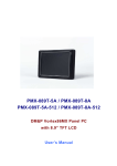
DM&P Vortex86MX+
Panel PC with 9” TFT LCD
Model:
PMX-090T-5A / PMX-090T-8A
PMX-090T-5A-512 / PMX-090T-8A-512
(Revision 1.0A)
i
Revision
Date
Version
Description
2012/11/20
Version 1.0
Initial Release
i
Copyright
The information in this manual is subject to change without notice for
continuous improvement in the product. All rights are reserved. The manufacturer
assumes no responsibility for any inaccuracies that may be contained in this
document. And makes no commitment to update or to keep current the
information contained in this manual.
No part of this manual may be reproduced, copied, translated or transmitted,
in whole or in part, in any form or by any means without the prior written
permission of the ICOP Technology Inc.
Copyright 2012 ICOP Technology Inc.
Manual No. IUMPMX090-01 Ver.1.0A Nov, 2012
Trademarks Acknowledgmen
Vortex86MX is the registered trademark of ICOP Technology Inc. Other
brand names or product names appearing in this document are the properties and
registered trademarks of their respective owners. All names mentioned herewith
are served for identification purpose only.
Safety Information
Read these Safety instructions carefully.
Make sure the voltage of the power source is correct before connecting the
equipment to the power outlet.
Do not expose your Panel PC to rain or moisture, in order to prevent shock
and fire hazard.
Keep PMX-090T away from humidity.
Do not open the cabinet to avoid electrical shock. Refer to your nearest
dealer for qualified personnel servicing.
Never touch un-insulated terminals or wire unless your power adaptor is
disconnected.
Locate your Panel PC as close as possible to the socket outline for easy access
and to avoid force caused by entangling of your arms with surrounding cables
from the Panel PC.
USB connectors are not supplied with Limited Power Sources.
If the equipment is not used for a long time, disconnect it from the power
source to avoid damage by transient overvoltage.
DO NOT ATTEMPT TO OPEN OR TO DISASSEMBLE THE CHASSIS (ENCASING) OF THIS
PRODUCT. PLEASE CONTACT YOUR DEALER FOR SERVICING FROM QUALIFIED TECHNICIAN.
ii
PMX-090T
DM&P Vortex86MX+ Panel PC with 9” WSVGA TFT LCD
Table of Contents
1
2
3
General Information .............................................................................. 3
1.1
Product Description...................................................... 1
1.2
Product Specification ................................................... 2
1.3
Inspection standard for TFT-LCD Panel ........................ 4
1.4
Product Dimension ....................................................... 7
1.5
Ordering Information ................................................... 8
1.6
Packing List ................................................................... 8
System Installation ................................................................................ 9
2.1
CPU Board Outline........................................................ 9
2.2
Connector Summary .................................................. 10
2.3
Connector Pin Assignments........................................ 11
2.4
External I/O Overview ................................................ 13
2.5
External I/O Pin Assignment ....................................... 14
2.6
System Mapping ......................................................... 16
2.7
Watchdog Timer ......................................................... 20
Driver Installation ................................................................................ 21
3.1
PMX-090T Development Note ................................... 22
3.2
BIOS Default setting ................................................... 24
Warranty......................................................................................................... 25
iii
PMX-090T
DM&P Vortex86MX+ Panel PC with 9” WSVGA TFT LCD
1 .General Information
1.1 Product Description
PMX-090T is an ultra-compact platform for the present demanding
embedded and productive applications. It has new Vortex86MX SoC CPU which
consumes only minimum power requirement when running at 1GHz, and DDR2
memory provides faster data transfer rate. By using 9” TFT LCD, PMX-090T
becomes the perfect choice for a limited budget. In additional, the integrated
10/100M Ethernet port supplies the communication capability which makes
PMX-090T can be more widely used when running with Linux, Windows CE, and
Windows XP environment to become the perfect solution for system integration.
1
PMX-090T
DM&P Vortex86MX+ Panel PC with 9” WSVGA TFT LCD
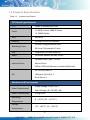
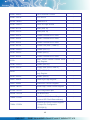
1.2 Product Specification
Table 1-1
Product Specification
CPU Board Specifications
CPU
DM&P Vortex86MX+ 1GHz
L1:16KB I-Cache, 16KB D-Cache
Cache
L2: 256KB Cache
BIOS
AMI BIOS
Memory
512MB/1GB DDR2 onboard
Software programmable from
Watchdog Timer
30.5u to 512 seconds x 2 sets
LAN
Integrated 10/100M Ethernet
Audio
HD Audio-Realtek ALC262 CODEC
Compact Flash Type I / II slot
Micro SD slot
Internal Drives
1GB or 2GB Flash Memory onboard (Optional)
RS-232/422/485 x 1
USB ports (Ver2.0) x 2
I/O
RJ-45 Port x 1
Mechanical & Environment
Power Requirement
Power Consumption
Operating
Temperature
Storage
Temperature
Single Voltage +5VDC ( 5A )
Multi Voltage +8~+35VDC ( 8A )
1.5A@5VDC
0 ~ +50℃ ( 32 ~ +122℉)
-10 ~ +60℃ ( 14 ~ +140℉)
2
PMX-090T
DM&P Vortex86MX+ Panel PC with 9” WSVGA TFT LCD
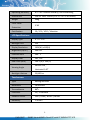
Operating Humidity
0% ~ 90% relative humidity, non-condensing
Dimensions
236.6 x 146 x 35mm (9.31 x 5.75 x 1.38 inches)
Weight
468g
Front Panel
IP 65
Protection
Certification
CE / FCC / VCCI / Vibration
LCD Specifications
Display Type
9” TFT LCD
Backlight Unit
LED
Display Resolution
2
1024(W) x 600(H)
Brightness (cd/m )
300 nits
Contrast Ratio
500 : 1
Display Color
262, 144
Pixel Pitch (mm)
190.5 (H) x 189 (V)
o
Viewing Angle
Backlight Lifetime
Vertical 120 ,
Horizontal 140
o
25,000 hrs
Touchscreen
Type
Analog Resistive
Resolution
Continuous
Transmittance
80%
Controller
PS / 2 interface
Software Driver
DOS / Linux / WinCE / WinXP
Durability
1 million
3
PMX-090T
DM&P Vortex86MX+ Panel PC with 9” WSVGA TFT LCD
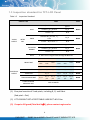
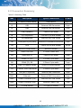
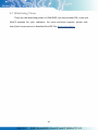
1.3 Inspection standard for TFT-LCD Panel
Table 1-2
Inspection Standard
DEFECT TYPE
LIMIT
SPOT
VISUAL
DEFECT
FIBER
INTER
NAL
POLARIZER
BUBBLE
Mura
φ<0.15mm
Ignore
0.15mm≦φ≦0.5mm
N≦4
0.5mm<φ
N=0
0.03mm<W≦0.1mm, L≦
5mm
N≦3
1.0mm<W, 1.5mm<L
N=0
φ<0.15mm
Ignore
0.15mm≦φ≦0.5mm
N≦2
0.5mm<φ
N=0
DARK DOT
ELECTRICAL
DEFECT
C
Area
O
Area
N≦0
N≦2
TOTAL DOT
TWO ADJACENT DOT
Note1
Note1
Note1
It’ OK if mura is slight visible through 6%ND filter
A Grade
BRIGHT DOT
Note
B Grade
Total
C
Area
O
Area
Total
Note3
N≦2
N≦2
N≦2
N≦3
N≦5
Note2
N≦3
N≦3
N≦3
N≦5
N≦8
N≦5
N≦6
N≦8
Note2
N≦1
pair
N≦1
pair
N≦1
pair
Note4
N≦4
N≦1
pair
N≦0
THREE OR MORE
N≦1
pair
NOT ALLOWED
ADJACENT DOT
LINE DEFECT
NOT ALLOWED
(1) One pixel consists of 3 sub-pixels, including R, G, and B dot.
(Sub-pixel = Dot)
(2) LITTLE BRIGHT DOT ACCEPTITABLE UNDER 6 % ND-Filter
(3) If require G0 grand (Total dot N≦0), please contact region sales.
4
PMX-090T
DM&P Vortex86MX+ Panel PC with 9” WSVGA TFT LCD
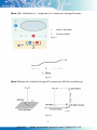
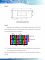
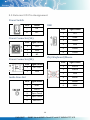
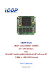
[Note 1] W : Width[mm], L : Length[mm], N : Number, φ: Average Diameter.
1.
White / Black Spot
2.
Polarizer Bubble
Fig 1-1
Fig 1-2
[Note 2] Bright dot is defined through 6% transmission ND Filter as following.
Fig 1-3
5
PMX-090T
DM&P Vortex86MX+ Panel PC with 9” WSVGA TFT LCD
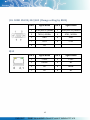
[Note 3]
C Area: Center of display area
O Area: Outer of display area
[Note 4]
Judge defect dot and adjacent dot as following. Allow below (as A, B, C and D
status) adjacent defect dots, including bright and dart adjacent dot. And they will
be counted 2 defect dots in total quantity.
A
C
R GB R GB R GB R GB R GB R GB
R Defect Dot
R GB R GB R GB R GB R GB R GB
R Adjacent Dot
R GB R GB R GB R GB R GB R GB
B
D
(1) The defects that are not defined above and considered to be problem shall
be reviewed and discussed by both parties.
Defects on the Black Matrix, out of Display area, are not considered as a defect or
counted.
6
PMX-090T
DM&P Vortex86MX+ Panel PC with 9” WSVGA TFT LCD
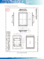
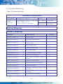
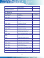
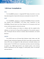
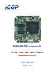
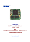
1.4 Product Dimension
Fig 1-4 Product Dimension
7
PMX-090T
DM&P Vortex86MX+ Panel PC with 9” WSVGA TFT LCD
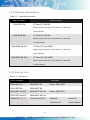
1.5 Ordering Information
Table 1-3
Ordering Information
PART NUMBER
DESCRIPTION
PMX-090T-5A
9” Panel PC w/1GB
DDR2 / 2USB / Line-Out / LAN / COM / CF / MicroSD /
Power Adapter
PMX-090T-8A
9” Panel PC w/1GB
DDR2 / 2USB / Line-Out / LAN / COM / CF / MicroSD /
8-35 DC Support
PMX-090T-5A-512
9” Panel PC w/512MB
DDR2 / 2USB / Line-Out / LAN / COM / CF / MicroSD /
Power Adapter
PMX-090T-8A-512
9” Panel PC w/512MB
DDR2 / 2USB / Line-Out / LAN / COM / CF / MicroSD /
8-35 DC Support
1.6 Packing List
Table 1-4
Packing List
PART NUMBER
PACKAGE
PMX-090T-5A
PMX-090T-5A
Power-20W-3PIN
PMX-090T-8A
PMX-090T-8A
PMX-090T-5A-512
PMX-090T-5A-512
PMX-090T-8A-512
PMX-090T-8A-512
WLAN KIT (Optional)
USB-WLAN-IPEX-KIT
Power-20W-3PIN
WIRELESS-
WIRELESS-
ANTENNA-157
CABLE-150MM
8
PMX-090T
DM&P Vortex86MX+ Panel PC with 9” WSVGA TFT LCD
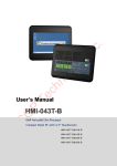
2 .System Installation
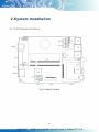
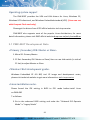
2.1 CPU Board Outline
Fig 2-1 PMX CPU Board
9
PMX-090T
DM&P Vortex86MX+ Panel PC with 9” WSVGA TFT LCD
2.2 Connector Summary
Table 2-1 Summary Table
Nbr
Description
Type of Connections
Pin nbrs.
J1
CF Master/Slave Switch
Slide Switch
ON/OFF
J3
USB
External USB Connector
6-pin
J4
USB
External USB Connector
6-pin
J5
USB (Optional)
2.0mm 5-pin wafer
5-pin
J8
PS/2 Keyboard
2.54mm 5-pin box header
5-pin
J9
PS/2Keyboard
External Mini DIN Socket
6-pin
J10
COM2(RS232/422/485)
External D-Sub Male Connector
9-pin
J14
VGA
2.0mm 10-pin box header
10-pin
J18
Micro SD Card Socket
Micro SD socket
J23
Audio Line-Out
1.25mm Phone Jack
J24
Audio Mic-In
2.0mm 4-pin wafer
4-pin
J25
COM3 (TX, RX)
1.25mm 3-pin wafer
3-pin
J26
COM4 (TX, RX
1.25mm 3-pin wafer
3-pin
J30
SOM CPU Board Socket
SOM CPU Board Socket
200-pin
J31
4-Wires Touch connector
1.25mm 4-pin wafer
4-pin
J32
USB (Wi-Fi Optional)
Internal USB Connector
6-pin
RJ45
Ethernet
External RJ45 Connector
8-pin
PWR
Power Connector (5A)
External Mini DIN Socket
3-pin
PWR
Power Connector (8A)
External Power Plug
2-pin
CF1
CF Card Socket
CF Type I/II Socket
10
PMX-090T
DM&P Vortex86MX+ Panel PC with 9” WSVGA TFT LCD
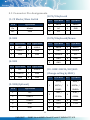
2.3 Connector Pin Assignments
J8: PS/2 Keyboard
J1: CF Master/Slave Switch
Pin #
Signal Name
Pin #
Signal Name
Pin #
Signal Name
1
KBCLK
2
KBDAT
On
Master
3
NC
4
GND
OFF
Slave
5
VCC
J3: USB
J9: PS/2 Keyboard/Mouse
Pin # Signal Name Pin # Signal Name
Pin #
Signal Name
Pin #
Signal Name
1
VCC
2
USBD2-
1
KBCLK
2
MSCLK
3
USBD2+
4
GND
3
GND
4
KBDATA
5
GND
6
GND
5
MSDATA
6
VCC
7
GND
8
GND
9
GND
J4: USB
Pin # Signal Name Pin # Signal Name
1
VCC
2
USBD3-
3
USBD3+
4
GND
5
GND
6
GND
J10: COM1 RS232/422/485
(Change setting by BIOS)
Pin #
Signal Name
Pin #
DCD1/
J5: USB (Optional)
1
422TX- /
Signal Name
RXD1 /
2
RS485-
422TX+ /
RS485+
Pin #
Signal Name
1
VCC
2
USBD1-
3
USBD1+
5
GND
6
DSR1
4
GND
7
RTS1
8
CTS1
5
GND
9
RI1
3
TXD1 /
422RX+
4
DTR1 /
422RX-
11
PMX-090T
DM&P Vortex86MX+ Panel PC with 9” WSVGA TFT LCD
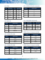
J14: VGA
J31: 4-Wires Touch connector
Pin #
Signal Name
GND
1
Y-
4
GND
2
X-
B OUT
6
GND
3
Y+
7
HSYNC
8
GND
4
X+
9
VSYNCD
10
GND
Pin #
Signal Name
Pin #
Signal Name
1
R OUT
2
3
G OUT
5
J24: MIC-IN
J32: USB (WiFi Optional)
Pin # Signal Name Pin # Signal Name
Pin #
Signal Name
1
MICVREF
1
VCC
2
USBD2-
2
GND
3
USBD2+
4
GND
3
GND
5
GND
6
GND
4
MIC-IN
PWR: Power Connector (5A)
J25: COM3 (TX, RX)
Pin #
Signal Name
Pin #
Signal Name
1
+5V
1
GND
2
GND
2
TXD3
3
NC
3
RXD3
4
GND
PWR: Power Connector (8A)
J26: COM4 (TX, RX)
Pin #
Signal Name
Pin #
Signal Name
1
GND
1
+ 8 ~ 35V
2
TXD4
2
GND
3
RXD4
12
PMX-090T
DM&P Vortex86MX+ Panel PC with 9” WSVGA TFT LCD
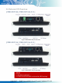
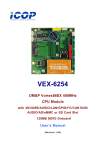
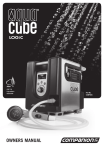
2.4 External I/O Overview
{ PMX-090T-8A / PMX-090T-8A-512 }
Fig 2-2 PMX-090T-8A I/O overview
{ PMX-090T-5A / PMX-090T-5A-512 }
Fig 2-3 PMX-090T-5A I/O overview
{Note}
1. Wireless is optional
2. COM1 RS232/422/485 is selected by BIOS setting)
13
PMX-090T
DM&P Vortex86MX+ Panel PC with 9” WSVGA TFT LCD
2.5 External I/O Pin Assignment
Power Switch
Pin #
Status
|
ON
O
OFF
USB
Power Connector (5A)
Pin # Signal Name
1
+5V
2
GND
3
NC
Pin # Signal Name
+8 ~ 35V
2
GND
Audio Line-Out
Pin # Signal Name
1
GND
2
LOUTL
3
Open Touch
4
Open Touch
5
VREFOUT
Signal Name
1
VCC
2
USB0-
3
USB0+
4
GND
5
GGND
6
GGND
PS/2 Keyboard/Mouse
Power Connector (8A)
1
Pin #
Pin #
Signal Name
1
KBCLK
2
PMCLK
3
GND
4
KBDAT
5
PMDAT
6
SB5V
14
PMX-090T
DM&P Vortex86MX+ Panel PC with 9” WSVGA TFT LCD
J10: COM1 RS232/422/485 (Change setting by BIOS)
RJ45
Pin #
Signal Name
Pin #
Signal Name
1
DCD1/422TX-/RS485-
2
RXD1/422TX+/RS485+
3
TXD1 / 422RX+
4
DTR1 / 422RX-
5
GND
6
DSR1
7
RTS1
8
CTS1
9
RI1
Pin #
Signal Name
Pin #
Signal Name
1
FTXD+
2
FTXD-
3
FRXIN+
4
NC
5
NC
6
FRXIN-
7
NC
8
NC
15
PMX-090T
DM&P Vortex86MX+ Panel PC with 9” WSVGA TFT LCD
2.6 System Mapping
Table 2-2 Technical Data Sheet
Technical Data Sheet
Product Name
PMX-090T-8A DM171C
Doc.No.
QMT1000014R00
Product
Description
9” Vortex86MX Panel PC with 1GB Doc. Category Confidential
DDR2 / 2USB / Line-out
/ LAN / 1COM / CF / MicroSD
Issued Date
10-08-2012
System Mapping
Memory Mapping
Address
Description
00000000-0009FFFF
System RAM
*
000A0000-000AFFFF
EGA/VGA Video Memory
*
000B0000-000B7FFF
MDA RAM,
Display RAM
000B8000-000BFFFF
CGA Display RAM
*
000C0000-000C7FFF
EGA/VGA BIOS ROM
*
000C8000-000CFFFF
Boot ROM Enable
000CC000-000CFFFF
Console Redirection Enable
000D0000-000D7FFF
Expansion ROM Space
000D8000-000DBFFF
SPI FLASH Emulation Floppy A
Enable
000DC000-000DFFFF
Expansion ROM Space
000E0000-000EFFFF
USB Legacy SCSI ROM Space
000F0000-000FFFFF
Motherboard BIOS
FEBD9000-FEBD90FF
FEBDA000-FEBDA0FF
FEBDB400-FEBDB4FF
Usage
Hercules
Standard OpenHCD
Controller
Standard OpenHCD
Controller
Graphics
*
*
USB
Host
USB
Host
On board Ethernet Adapter
*
*
*
16
PMX-090T
DM&P Vortex86MX+ Panel PC with 9” WSVGA TFT LCD
FEBDB800-FEBDB8FF
FEBDBC00-FEBDBCFF
Standard Enhanced
Host Controller
Standard Enhanced
Host Controller
PCI
to USB
PCI
to USB
*
*
I/O Mapping
I/O Address
Owner
Usage
0000h - 000Fh
DMA 8237-1
0010h - 0017h
COM 9
0020h - 0021h
PIC 8259-1
*
0022h - 0023h
Indirect Access Registers
( 6117D configuration port )
*
002Eh - 002Fh
Forward to LPC BUS
0040h - 0043h
Timer counter 8254
*
0048h - 004Bh
PWM counter 8254
*
004Eh - 004Fh
Forward to LPC BUS
0060h
Keyboard / Mouse Data Port
*
0061h
Port B + NMI Control Port
*
0062h - 0063h
8051 download 4K Address Counter
*
0064h
Keyboard / Mouse Status /
Command Port
*
0065h
WatchDog0 Reload Counter
*
0066h
8051 Download 8bit Data Port
*
0067h
WatchDog1 Reload Counter
*
0068h - 006Dh
WatchDog1 Control Register
*
0070h - 0071h
CMOS RAM Port
*
0072h - 0075h
MTBF Control Register
*
0078h - 007Ch
GPIO Port 0,1,2,3,4 Default Setup
*
0080h - 008Fh
DMA Page Register
*
0092h
System Control Register
*
*
17
PMX-090T
DM&P Vortex86MX+ Panel PC with 9” WSVGA TFT LCD
0098h - 009Ch
GPIO Direction Control
*
00A0h - 00A1h
PIC 8259-2
*
00C0h - 00DFh
DMA 8237-2
*
00E0h - 00EFh
DOS 4G Page Access
*
0170h - 0177h
IDE1 (IRQ 15)
*
01F0h - 01F7h
IDE0 (IRQ 14)
*
0220h - 0227h
COM8 Forward to LPC BUS
0228h - 022Fh
COM7 Forward to LPC BUS
0238h - 023Fh
COM6 Forward to LPC BUS
0278h - 027Fh
Printer Port (IRQ 7, DMA 0)
02E8h - 02EFh
COM4 (IRQ 11)
02F8h - 02FFh
COM2 (IRQ 3)
0338h - 033Fh
COM5 Forward to LPC BUS
0376h
IDE1 ATAPI Device Control Write
only Register
03E8h - 03EFh
COM3 (IRQ 10)
03F0h - 03F7h
Floppy Disk (IRQ 6, DMA 2)
03F6h
IDE0 ATAPI Device Control Write
only Register
*
03F8h - 03FFh
COM1 (IRQ 4)
*
0480h - 048Fh
DMA High Page Register
*
0490h - 0499h
Instruction Counter Register
*
04D0h - 04D1h
8259 Edge,/ Level Control Register
*
0CF8h - 0CFFh
PCI configuration port
*
DE00h - DEFFh
On Board LAN
*
FC00h - FC05h
SPI Flash BIOS Control Register
(internal SPI Flash Base address)
*
FC08h - FC0Dh
External SPI BUS Control Register
( Output Pin Configurable
GPIO3[0-3] )
*
18
PMX-090T
DM&P Vortex86MX+ Panel PC with 9” WSVGA TFT LCD
IRQ Mapping
IRQ#
Description
Usage
IRQ0
System Timer
*
IRQ1
Keyboard Controller
*
IRQ2
Cascade for IRQ8 - 15
IRQ3
USB
*
IRQ4
Serial Port 1
*
IRQ5
USB
*
IRQ6
Unassigned
IRQ7
Ethernet 10/100M LAN
*
IRQ8
Real Time Clock
*
IRQ9
USB
*
IRQ10
USB
*
IRQ11
Audio
*
IRQ12
Mouse
*
IRQ13
Math Coprocessor
*
IRQ14
Hard Disk Controller#1
*
IRQ15
Hard Disk Controller#2
*
DMA Mapping
DMA#
Description
Usage
DMA0
DMA1
DMA2
Floppy Disk Controller
DMA3
DMA5
DMA6
DMA7
19
PMX-090T
DM&P Vortex86MX+ Panel PC with 9” WSVGA TFT LCD
2.7 Watchdog Timer
There are two watchdog timers in PMX-090T, we also provide DOS, Linux and
WinCE example for your reference. For more technical support, please visit:
http://tech.icop.com.tw or download the PDF file: dmp.com.tw/tech
20
PMX-090T
DM&P Vortex86MX+ Panel PC with 9” WSVGA TFT LCD
3 .Driver Installation
VGA
The Vortex86MX processor is integrated RDC Display chip which is an ultra
low powered graphics chipset with total power consumption at around 1-1.5 W.
LAN
The Vortex86MX+ processor is integrated 10/100Mbps Ethernet controller
that supports both 10/100BASE-T and allows direct connection to your
10/100Mbps Ethernet based Local Area Network for full interaction with local
servers, wide area networks such as the Internet.
I/O and IRQ settings can be done by software with the supplied utility
software, or it can be set for Plug and Play compatibility. The controller supports:
Half / Full-Duplex Ethernet function to double channel bandwidth, auto media
detection.
AUDIO
The ALC262 series are 4-Channel High Definition Audio Codecs with UAA
(Universal Audio Architecture) featuring two 24-bit stereo DACs and three 20-bit
stereo ADCs, they are designed for high performance multimedia desktop and
laptop systems. The ALC262 series incorporates proprietary converter technology
to achieve over 100dB Signal-to-Noise ratio playback quality; easily meeting
PC2001 requirements and also bringing PC sound quality closer to consumer
electronic devices.
21
PMX-090T
DM&P Vortex86MX+ Panel PC with 9” WSVGA TFT LCD
Operating system support
The PMX-090T provides the VGA and LAN drivers for Linux, Windows CE,
Windows XP Professional, and Windows Embedded standard (XPE). (Linux can use
with Compact Flash card only.)
Please get the drivers from ICOP official website: tech.icop.com.tw
PMX-090T also supports most of the popular Linux distributions, for more
detail information, please visit DMP official website:dmp.com.tw/tech/vortex86mx
3.1 PMX-090T Development Note
<Primary /Secondary IDE: Master or Slave>
1. Micro SD: Primary Master
2. CF Slot: Secondary IDE: Master or Slave (User can use slide switch (in side of
CF slot) to adjust Master or Slave
<Window CE6.0 development guide>
Windows Embedded CE 6.0 BSP, trial CE image and development notes,
please visit technical website to get more information: tech.icop.com.tw
<Linux installation note>
Please forced the IDE setting in BIOS to PIO mode before install Linux
on PMX-090
T as follows:
3. Go to the advanced BIOS setting and make the “Onboard IDE Operate
Mode” is “Legacy Mode”
22
PMX-090T
DM&P Vortex86MX+ Panel PC with 9” WSVGA TFT LCD
4. Go to the PCI/PnP and make the “PCI IDE BusMaster” is “Disable"
< XP professional /Home /Embedded and Windows 2000
installation note >
Please visit technical website to get more information: tech.icop.com.tw
<Enhance CF to run the UDMA2/4>
Please select ICOP “ICF Card” to supporting UDMA 2/4 Mode.
<How to boot up from the Micro SD card>
1. Get into the BIOS setup Utility
2. Go to the Advanced
3. Choose Primary IDE Pin Select: SD card
4. Press “F10” to save configuration changes and exit setup
23
PMX-090T
DM&P Vortex86MX+ Panel PC with 9” WSVGA TFT LCD
3.2 BIOS Default setting
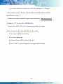
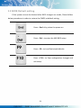
If the system cannot be booted after BIOS changes are made, Please follow
below procedures in order to restore the CMOS as default setting.
Press < End > Key, when the power on
Press < Del > to enter the AMI BIOS setup
Press < F9 > to Load Optimized defaults
Press < F10 > to Save configuration changes and
exit setup
24
PMX-090T
DM&P Vortex86MX+ Panel PC with 9” WSVGA TFT LCD
Warranty
This product is warranted to be in good working order for a period of one
year from the date of purchase. Should this product fail to be in good working
order at any time during this period, we will, at our option, replace or repair it at
no additional charge except as set forth in the following terms. This warranty does
not apply to products damaged by misuse, modifications, accident or disaster.
Vendor assumes no liability for any damages, lost profits, lost savings or any other
incidental or consequential damage resulting from the use, misuse of, originality
to use this product. Vendor will not be liable for any claim made by any other
related party. Return authorization must be obtained from the vendor before
returned merchandise will be accepted. Authorization can be obtained by calling
or faxing the vendor and requesting a Return Merchandise Authorization (RMA)
number. Returned goods should always be accompanied by a clear problem
description.
All Trademarks appearing in this manuscript are registered trademark of their respective owners.
All Specifications are subject to change without notice.
©ICOP Technology Inc. 2012
25
PMX-090T
DM&P Vortex86MX+ Panel PC with 9” WSVGA TFT LCD