1
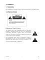
Contents
Section PAGE
1.0
2.0
3.0
4.0
5.0
6.0
7.0
GENERAL
1.1 Warning
1.2 Precautions
1.3 Introduction
IMPORTANT SAFEGUARDS
SCOPE
3.1 Accessories
3.2 Features
FUNCTIONS
4.1 Front panel controls
4.2 Rear panel controls
OPERATION & TROUBLESHOOTING
INSTALLATION
SPECIFICATIONS AND SAFETY
7.1 Observation monitor with built-in 4-channel switcher
7.2 Compatible cameras & cable
7.3 Safety
CAMSET6
1
GB
1.0 GENERAL
1.1 WARNING
Do not expose this monitor to rain or moisture to prevent fire or shock hazard.
1.2 PRECAUTIONS
CAUTION
RISK OF ELECTRIC SHOCK
DO NOT OPEN
CAUTION:
TO REDUCE THE RISK OF ELECTRIC SHOCK, DO NOT
REMOV COVER (OR BACK), NO USER-SERVICEABLE
PARTS INSIDE, REFER SERVICING TO QUALIFIED
SERVICE PERSONNEL.
Explanation of Graphic Symbols
The lightning flash with arrowhead within an equilateral
triangle is intended to alert the user to the presence of
uninsulated "dangerous voltage" within the product's
enclosure that may be of sufficient magnitude to constitute
a risk of electric shock to persons.
The exclamation point with an equilateral triangle is
intended to alert the user to the presence of important
operating and maintenance (servicing) instructions in the
literature accompanying the appliance.
CAMSET6
2
GB
1.3 INTRODUCTION
This powerful observation system comprises one 12" B/W high-resolution
monitor with a 4-channel switching function, a 1/3" CCD camera fed with a
single line and also 15m of cable. The latter two element scan be ordered
separately. Apart from the alarm triggering via the monitor, the recorded
images are also very important as they can be displayed simultaneously on
the monitor. Furthermore, not only PIRs or magnetic contacts can be used:
you can also use any type of NC/NO detection method to activate this
system. More than simply state-of-the-art, this system includes optional oneway / two-way audio functions, providing teh surveillance team with direct and
perfect monitoring access to the location where noise and activity have been
reported. Thanks to the possibility of connecting up to 3 additional cameras,
this system enables the user to monitor no less than 4 different locations. The
user can select a specific channel via the buttons on the control panel at the
front of the device. This system is a fully integrated security tool, which can
also be used to trigger a time-lapse VCR, switch on lights, etc… The system
is easy to install and it is the ideal solution for the protection of your retail
business, your lobby, or even your private residence.
2.0 IMPORTANT SAFEGUARDS
Read the safety and operating instructions before bringing the device into
service.
1.
2.
3.
Save the instructions : Leave these instructions in a safe place for
future reference.
Heed the warnings : Respect the warnings on the monitor and in the
user manual.
Follow the instructions: All isntructions concerning safety and
operation should be resepected.
CAMSET6
3
GB
4.
Cleaning : Unplug the monitor from the wall outlet before cleaning. Do
not use liquid cleaners or aerosol cleaners. Use a damp cloth for
cleaning. Exception: Some monitors are meant for uninterrupted service
and cannot be unplugged (e.g. risk of losing an authorisation code for a
cable TV converter), not even for cleaning purposes. For these
applications the user can disregard the reference to unplugging the
monitor prior to cleaning.
5. Attachments : Do not use any attachmnts not recommended by the
manufacturer as they may cause hazards.
6. Water and moisture : Do not use this monitor near water e.g. a bathtub,
a washbasin, a sink, in wet basements, near a swimming pool, etc.
7. Accessories : Do not palce this monitor on an unstable cart, stand,
tripod, bracket or table. The monitor may fall, causing serious injury to
children or adults, and serious damage to the device. Only use
accessories recommended by the manufacturer or sold with the monitor.
Mount the monitor according to the manufacturer's instructions.
8. Ventilatie : The housing has slots and openings to keep the device from
overheating and to ensure reliable operation. Never block these
openings by palcing the monitor on a bed, a sofa, a rug or a similar
surface. Do not place the monitor near or on a radiator or any other heat
source. Do not place the monitor in a built-in installation, on a bookcase
or in a rack unless they are properly ventilated or the manufacturer's
instructions have been respected.
9. Power source : This monitor should only be used with the type of powre
source mentioned on the manufacturing label. If you are not sure about
the type of power supply to use, please contact your dealer or the local
power company.
10. Earthing or polarisation : For monitors equipped with a 3-wire
grounding type plug having a third (grounding) pin. This plug will only fit
into a grounding-type power outlet. This is a safety feature. If you are
unable to insert the plug into the outlet, contact your electrician to
replace the outlet. A grounded plug offers an extra safety guarantee, so
take care of that plug.
CAMSET6
4
GB
11. Power : Cord protection – Make sure the power cables cannot be
pinched or dragged along by objects placed on top of or next tot hem.
Pay particular attention to power cables near outlets, receptacles and the
point where the cable exits the monitor.
12. Lighting : Unplug the device and disconnect the cables to protect the
device during a storm or when the monitor is to be left unattended or
unused for long periods of time. This will keep the monitor from being
damaged by lightning or surges in the power cables.
13. Overload : Do not overload wall outlets or extension cords as this can
lead to fire or electric shocks.
14. Penetration by objects or liquids : Do not push any objects through
the openings in the housing as these could touch points that are under
tension, which could result in fire or electroshocks. Do not spill liquids of
any kind on or in the monitor.
15. Maintenance : Do not attempt to service the device yourself as opening
or removing covers may expose you to dangerous voltages or other
hazards. Refer all servicing to qualified service personnel.
16. Damage requiring service – Unplug the monitor and consult a qualified
technician in the following cases :
a. when the power supply cord ior the plug is damaged ;
b. if a liquid has been spilled on or in the monitor or when an object has
fallen into the housing ;
c. if the monitor has been exposed to rain or moisture ;
d. if the monitor doesn't work normally even though the operating
instructions are being followed. Only adjust the controls that are
described in the manual. Changing other controls may result in severe
damage to the device ;
e. if the monitor has been dropped or if the housing is damaged ;
f. have the device serviced if the monitor exhibits a distinct change in
performance.
17. Spare parts – If spare parts are necessary, you should make sure the
service technician only uses spare parts specified by the manufacturer or
parts having identical specifications. Unauthorised replacement may
reulst in fire, electroshocks or other hazards.
CAMSET6
5
GB
3.0 SCOPE
3.1 Accessories
This package basically includes
1 x monitor (12 ")
1 x CCD camera 1/3" (max. 4 pcs)
1 x 15m of coax cables
1 x user manual
1 x power cord
3.2 Features
•
•
•
•
•
•
•
•
One high-resolution B/W monitor with built-in 4-channel switcher
Automatic selection of camera channels via alarm triggering
One-way or two-way audio function
Signal input from up to 4 cameras
Line-fed 1/3" CCd camera, 380 TV lines, 3.6mm fixed iris
Dwell time adjustable between 2 – 30 sec. for each camera
VA/V output supply for use in combination with a VCRr
Alarm input with Normally Open / Normally Closed selector at the back
CAMSET6
6
GB
4.0 Function Description
4.1 Front Panel Controls
1.
Power ON/OFF Switch
To turn the device ON or OFF.
2.
Auto/Reset Switch
-- Normal Status (without alarm): push the "auto/reset" button, the
ysstem will auto-scan the camera channels.
-- Abnormal Status (the alarm is ON): press the "Auto/Reset" button to
release the alarm. The device will now be reset and will return to the
normal status (see above).
-- Remark : The system is equipped with a special auto scan function for
camera channels. If only 3 cameras are connected e.g. channels 1, 3
& 4, then these three channels will be displayed sequentially and
channel will be ignored to save scanning frequency.
3.
TALK (compatible only with a two-way audio function like in the
standard camera)
Enables you to talk to the selected channel where the event is taking
place. Note that you need to connect a MICROPHONE to the system
first via the MIC-connection. The LED for a particular camera channel will
light when that channel has been selected. Press the "TALK" button
before you say anything and wait until the "TALK" LED lights up. You can
then speak into the microphone to address the person next to the
selected camera. Press "TALK" again when you stop talking so you can
hear your interlocutor's reply.
CAMSET6
7
GB
4.
VCR
This button makes it possible to display VCR images on the screen.
When you press this button, the VCR LED will light and you can watch
the video feed on the screen.
5.
Channel 1-4
These buttons enable you to select the channel of a particular camera.
The LED of the selected channel will light and the screen will display the
picture from the selected channel.
6.
MIC Connection – microphone can be ordered separately
Allows connection of a microphone to the system. The microphone is tob
e used in combination with the TALK button (see above).
7.
VOLUME
Increase or decrease the volume of the camera channels with this
button.
8.
TIME
Permits adjustment of the dwell time per channel (2 – 30 sec.).
9.
CONTRAST
Allows adjustment of the contrast between the black and white portions
of the picture.
10. BRIGHTNESS
This button adjusts the overall brightness of the picture. It is used to
compensate for differences in ambient light.
11. VERTICAL-HOLD
Permits adjustment of the vertical stability. Turn this button to the left or
right to stabilise the picture.
12. HORIZONTALE SYNCHRONISATIE
Permits adjustment of the horizontal stability. Turn this button to the left
or right to stabilise the picture.
CAMSET6
8
GB
4.2 Rear Panel Controls
GND
Alarm trigger
in (option)
MIC output
Video
input
DC 12V
Audio input
ALARM
INPUT
MODE
TIME MODE
OUTPUT
ALARM
VCR
AUTO
RECORD
13. CAMERA 1-4
Allows signal input of up to 4 cameras for audio, power, MIC, GND,
alarm and video.
14. VIDEO IN & OUT
Used as an input and output for images from and to the VCR. The
images from the VCR arrive in "IN" and images are sent to the VCR in
"OUT".
15. AUDIO IN & OUT
Used as a input and output for the sound from and to the VCR. The
sound signals from the VCR arrive in "IN" and sound signals are sent to
the VCR in "OUT".
CAMSET6
9
GB
16. ALARM INPUT MODE 1-4
Operates the NO/NC switch of the alarm inputs for the 4 cameras. Note
that, for integrated application purposes, each camera can be connected
with PIRs, magnetic contacts or any type of sensor, this for Merk op dat
elke camera met het oog op de geïntegreerde toepassingen kan worden
verbonden met PIRS, met magnetische contacten of met elk soort
sensoren.
17. TIME MODE
Permits alarm time selection per channel. Put the switch in the A (45
seconds) or B (90 seconds) position.
18. ALARM OUTPUT
Permits alarm relay output. The NC /NO / COM modes can be selected,
but hould match the desired alarm signals such as buzzers, burglar
alarm or time-lapse recordings.
19. VCR AUTO RECORD
-- Abnormal status (the alarm is ON): the VCR records the images
automatically.
-- Normal status (without alarm): the VCR no longer records images.
5.0 OPERATION & TROUBLESHOOTING
5.1 Operation
1.
Power On
Situation I : without camera signal input
Press the ON/OFF button and the green LED will light. The monitor
display is blank.
Situation II : with camera signal input
Press the ON/OFF button and the green LED and the AUTO RESET
LED will light simultaneously. The video signals are displayed
momentarily in the order in which they are received.
2.
Manual / Auto Selector
The input of up to 4 cameras is sent ot the monitor before the next step
is executed.
Situation I: manual switching
Press a button for one of the 4 channels or for the VCR. The LED for the
selected channel will light.
P.S. Make sure a VCR is connected to the monitor when you're trying to
record images. The rear panel has a VCR input (AUDIO/VIDEO IN)
where the video signal is received; the images are sent to the monitor
CAMSET6
10
GB
via this input. The system is also equipped with a video output
(AUDIO/VIDEO OUT) that sends images to the VCR with a view to
making recordings.
Situation II : automatic switching
Press the "AUTO/RESET" button. The system automatically starts to
detet the video signals from channel 1 to 4. If 4 cameras are connected,
the system will start detecting at channel 1 and then move to channels 2,
3 & 4. The system will skip any chanel that is not activated. The dwell
time can be set between 2 to 30 seconds with the TIME adjustment on
the front panel.
3.
Alarm
If you want to use the alarm function we advise you to start by
familiarising yourself with the camera type to be used. Please consult
your dealer for detailed information if necessary.
Preparation
Choose a camera with an alarm function. Install the camera in a location
where discreet observation is required. Insert an alarm relay terminator if
necessary and set up the alarm mode according to your alarm input
mode (NO/NC/COM).
Situation I : The alarm on 1 channel has been activated
When visitors or intruders are detected on a particular channel, the LED
for that channel lights up and the alarm relay is activated simultaneously.
If the "REC/STOP" function is connected, then the VCR will automatically
store the images. You can set the alarm time via the time mode on the
front panel: you can select A (45 seconds) or B (90 seconds). Prss the
"AUTO/RESET" button on the front panel of the monitor to release the
alarm and start the video recording.
Situation II : The alarm has been activated on multiple channels
If the alarm has been activated on multiple channels, the system will
always display the signal of the channel where the alarm was activated
last. Press AUTO/RESET to release the alarm and start the video
recording.
CAMSET6
11
GB
4.
TALK
You must connect a microphone to the system before you can use this
button. This function can only be used in case of manual operation or in
the "alarm ON" mode. Select your channel and press the button. Press
the TALK button and speak if you only want to be able to address your
visitor. Use a camera with a two-way audio function if you want to be
able to converse with your visitor.
5.2 Troubleshooting
Incorrect use of the system may cause problems and may result in
malfunction. Before calling in a qualified technician, you should use the
following checklist first. You can still contact your dealer for a more
detailed inspection if the checklist is unabled to provide a solution.
The system does not come on even though the ON/OFF button is
pressed.
Check to see if the power cord is connected securely.
The picture is not clear.
Check the image controls (e.g. contrast, brightness, ...).
Everything is displayed in mirror image.
Check to see if there is a glass surface in front of the camera. If not, contact
your dealer for further examination.
No image is displayed.
Make sure the video cable and the camera are connected securely.
CAMSET6
12
GB
6.0 INSTALLATION
CAM7 (included)
Pattern I
CAM8 (option)
Pattern II
Pattern III
Other type
cable
DETECTION SYSTEM
(option)
REAR PANEL VCR
ALARM
INPUT
MODE
TIME MODE
OUTPUT
ALARM
VCR
AUTO
RECORD
CAMSET6
13
GB
7.0 SPECIFICATIONS & SAFETY
7.1 Observation monitor with built-in 4-channel switcher
Picture tube
Input rating
Operation Voltage
Power Consumption
Input Signal
Output Signal
In/Out Impedance
Sequential Time
Horizontal resolution
Centre
Corner
Operation System
CCIR – Horizontal
Vertical
Connections
Camera input
Video in/out
Audio in/out
Alarm in/out
Alarm Out
Alarm Input Type
Alarm Time Mode
Environment
Construction
Front Controls
ON/OFF Switch
Horizontal and Vertical
Synchronisation
Contrast / Brightness
Sequentia Time / volume
CAMSET6
12"
100-240 V CA
96-256 V CA 60Hz/50Hz
30W
Video / Audio (4 x)
VCR signal (1x)
Composite 0,5 - 2,0 Vp-p
Sync. Negative
A/V output to the VCR or a second monitor
Composite 1,0 Vp-p
Sync. Negative
75 ohms
Automatic switching when dwell time is over.
Dwell time can be set individually for each
camera : 2 to 30 seconds
1000 TV lines
800 TV lines
15625Hz ± 400Hz
50Hz
4 mini-DIN connectors
RCA connections (2x)
RCA connections (2x)
terminal block on PCB
Relay NO / NC out
DIP switch (NC. NO contact input switchable)
adjustable from 2 to 40 seconds
indoors
Steel housing with plastic front panel
Rotary switch
Rotary switch
Rotary switch
Rotary switch
14
GB
7.2 Compatible Cameras and Cable
CAMERA
Pattern
Dimensions (mm)
Power Consumption
Pick-Up Device
Picture Elements
CCIR
Hor. resolution
Min. illumination
Scanning System
CCIR
Gamma Correction
S/N Ratio
Sync. System
Shutter Control
CCIR
Video output
Courant
Frequency
Horizontal
Vertical
DC Power Source
Operation Temperature
Audio output
Kabel
CAMSET6
CAM7 (INCLUDED)
B/W CCD camera (1/3")
94 x 81x 74
2 w (max)
1/3" image sensor with
interline transfer CCD
CAM8 (OPTION)
waterproof spot
251x192 (L x H)
V
V
500 (H) x 582 (V)
380 TV lines
0.1 lux/Fl.4
V
625 lines / 50 fields
V
0,45/1 (default value set prior to shipment)
> 45dB (AGC off)
Internal synchronisation
1/50 - 1/10.000 sec.
Composite 1.0Vp-p / 75Ω
110mA (Max)
CCIR
15.625KHz
50Hz
12V DC from monitorr
-10 to 50°C (14 to 122°F)
one-way or two-way
15m of coax cable
15
V
V
V
V
One-way
V
GB
7.3 Safety
CE-Label : Warning
This product belongs to Class A. In a domestic environment this product may
cause radio interference in which case the user may be required to take
adequate measures.
FCC – COMPLIANCE STATEMENT
This equipment has been tested and found to comply with limits for a class B
digital device, pursuant to Part 15 of the FCC rules. These limits are designed
to provide reasonable protection against harmful interference in residential
installations. This equipment generates, uses, and can radiate radio
frequency energy, and if not installed and used in accordance with the
instructions, may cause harmful interference to radio communications.
However, there is no guarantee that interference will not occur in a particular
installation. If this device does interfere with radio or television reception,
which can be determined by switching the device OFF and ON, the user is
encouraged to try and correct the interference by one or more of the following
measures:
- reorient or relocate the antenna
- increase the distance between the device and the receiver
- plug into an outlet connected to a different electrical circuit
- contact your dealer or a nexperienced radio or TV technician for
additional advice.
Only equipment certified to comply with Class B should be connected with
this device, otherwise you will be in violation of the FCC emission limits.
Furthermore, all devices should be equipped with shielded cable.
We would like to point out that every modification of or adjustment to the
device that has not been expressly approved by the party responsable for
compliance may void your authority to use this type of device.
The information in this manual can be subject to change without prior notice.
CAMSET6
16
GB