1
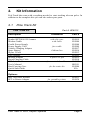
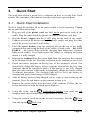
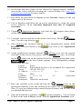
Pole Track
User’s Manual
HPK012 Contractor Kit
7-2-2003
This document contains training information specifically designed for the
Hayton Systems Pole Track application. Pole Track is designed and licensed by
Hayton Systems. Any required changes to this document or the application
should be forwarded to Verizon Network Services – Infrastructure Provisioning
Systems Support.
Hayton Systems
3210 Smokey Point Drive #200
Arlington, WA 98223
360-659-5804
fax 360-659-6823
800-990-8360
www.haytonsystems.com
Verizon Approved
by Dennis Brooks
[email protected]
972-718-6150
This document contains Hayton Systems Confidential and Proprietary
Information. Users shall maintain such Confidential and Proprietary
Information in confidence until such information is made publicly available
by Hayton Systems. Users shall take reasonable precautions to limit the
disclosure of such Confidential and Proprietary Information only to your
employees who are necessary to evaluate and/or use such information.
Contents
1.
INTRODUCTION......................................................................... 1
2.
KIT INFORMATION ................................................................... 2
2.1
3.
2
Q UICK START.......................................................................... 6
3.1
3.2
4.
Pole Track Kit
Quick Start Installation
Quick Start Handheld
6
9
THE HANDHELD TERMINAL.................................................... 10
4.1
4.2
4.3
Standard Applications
Scanning Notes
Entering Text
12
12
13
5.
S ET DATE AND TIME.............................................................. 14
6.
APPLICATION LAUNCHER AND RESTORER................................ 15
7.
S TART POLE TRACK AND ENTER SETTINGS ............................ 16
7.1
8.
Maintaining the List of Auditors
17
TRACKING POLE ASSETS........................................................ 18
8.1
8.2
8.3
DATA View
Data View Fields
Add, Edit, Delete Attachments
18
19
20
9.
UTILITIES.............................................................................. 21
10.
GPS CHECK UTILITY PROGRAM ........................................... 23
APPENDIX A – GRAFFITI ................................................................. 24
APPENDIX B - DATA FORMATS ........................................................ 25
B.1 Pole Header Record
B.2 Pole Details Record
B.3 Pole Attachment Record
26
27
28
ASCII TABLE ................................................................................ 29
GLOSSARY ...................................................................................... 31
1.
Introduction
Power and telecom cables often use the same utility pole. Telecom companies
often lease space on poles owned by power companies (and vice versa). Telecom
companies pay a significant sum to power companies for this leased space.
Telecom lines are often moved and occasionally leased poles are no longer used.
Pole Track allows you to inventory poles so the power companies are paid only
for the poles actually used.
Pole Track Terminal
Pole Track operates on the Symbol SPT handheld terminal and uses an
operating system based on the Palm III operating system. Pole Track
terminals include some standard Palm III “organizer” functions, an
integrated bar code scanner, and a GPS module.
GPS Module
The GPS (Global Positioning System) module provides precise longitude
and latitude coordinates to Pole Track. The GPS module connects to the
bottom of the terminal and uses an internal antenna to receive the GPS data
from the satellites.
Tracking Poles
The terminal prompts for information about each pole and each pole
attachment. The terminal stores the collected pole data and you then send
the collected data to the Pole Track server. The server receives the pole data
and it uses this data to update its master database.
Summary
Pole Track provides an intuitive and efficient way to track the poles used
for telecom cables.
Pole Track © 2003, Hayton Systems
Page 1
2.
Kit Information
Pole Track kits come with everything needed to start tracking telecom poles. In
addition to the complete kits you can also order spare parts.
2.1
Pole Track Kit
Pole Track Kit
Part # HPK012
Description
Comments
Part #
Symbol SPT1800 1D Scanner
Modem Cradle
Cradle Power Supply
Power Supply Cord
Vehicle Charging Adapter
Spare Battery
Stylus 5 Pack
GPS Adapter
Modem Adapter
Serial/Charging Cable
SPT Soft Case
User’s Manual
Hard Carrying Case
Quick Start Guide
with slip case
with cable
H15019
H15004
H15008
H15009
H15017
H15016
H15013
H15025
H15012
H15010
H15007
HS2151
H15006
N/A
Options:
Jazz 150 Power Inverter
SPT to Printer Adapter
Pole Track © 2003, Hayton Systems
for cradle
Lithium Ion
9-pin to 25-pin
for terminal & cables
for the entire kit
for portable printer
H15031
H15030
Page 2
2.2
Parts List
The Contractor Kit contains these components. Contact Hayton Systems to
reorder components or accessories.
H15019
Symbol SPT1800
with 1D Scanner
H15004
Modem Cradle
(with cable)
H15025
GPS Adapter
H15008
Cradle Power
Supply
H15009
Power Supply
Cord (for Cradle)
H15016
Spare Battery
(Lithium Ion)
H15013
Stylus 5 Pack
H15012
Modem Adapter
(9-pin to 25-pin)
H15010
Serial/Charging
Cable
H15007
Soft Case for
Terminal and
Cables
H15006
Hard Carrying
Case (for the
entire kit)
HS2151
User’s Manual
Pole Track © 2003, Hayton Systems
Page 3
2.3
Repair Procedures
Send hardware in need of repair to Hayton Systems for processing. The SPT
terminal, modem cradle, and GPS adaptor are the only components considered
repairable. All other components are considered as expendable items that are not
economical to repair due to their low initial cost.
Contact Hayton Systems at http://www.haytonsystems.com/support/repairs.htm
(or call 360-403-9194) to begin the repair process. Complete and submit the
online Return Authorization (RA) Form. After submitting the RA you will
receive an RA number via email. Print two copies of the authorization: one copy
for your records and enclose one with hardware being returned. The repair
process normally takes three to four weeks.
You can make a copy of this shipping label and use it when returning the
equipment.
From: Name
___________________________
_
Address
___________________________
_
City/State/ZIP
___________________________
_
RMA Number ____________________
To:
Hayton
Systems
Attn:
Wayne
Hayton
st
19007 61
Ave NE Unit 3
Arlington, WA 98223
Pole Track © 2003, Hayton Systems
Page 4
Arlington, WA 98223
Pole Track © 2003, Hayton Systems
Page 5
3.
Quick Start
The quick start section is meant to be a reference on how to use the Pole Track
system. The remainder of the manual describes each step in greater detail.
3.1
Quick Start Installation
The Pole Track kit includes all of the parts needed to begin operating. Unpack
the kit and follow these steps:
1. Plug one end of the phone cord into the Line-In port on the back of the
cradle. Plug the other end of the phone cord into a telephone wall jack.
2. Plug the Power Supply into the 9 VDC plug on the back of the cradle.
Connect one end of the power cord to the power supply and plug the other
end of the power cord into a wall outlet.
3. Place the spare battery into the charging slot on the top of the cradle
(contacts down and facing the back of the cradle). Gently push – DO NOT
FORCE -- the battery down until the charging light illuminates (leftmost
light on the cradle). A red light means the battery is charging and green
means it is fully charged.
4.
Remove the terminal from the yellow Soft Case. Do not place the terminal
in the Modem Cradle yet. Press the red button on the terminal to turn it on.
5. Check the battery indicator on the top line of the terminal’s screen. You
should fully charge the battery before using the terminal for the first time
(indicator should be completely black). If the battery is not fully charged
then place the terminal in the cradle to completely charge the battery (about
30 minutes maximum). The charging light will be red if the battery is
charging and green if the battery is fully charged.
6.
After the battery has been fully charged you are ready to start setting up the
terminal. Press the red button on the terminal to turn it on.
7. Remove the yellow stylus from the back of the terminal. Follow the onscreen directions to align the touch screen digitizer.
8. Using the stylus, tap the
Application Launcher icon until the All
category name shows on the upper right corner of the screen.
9. Using the vertical scroll bar on the screen if necessary, find the
icon and tap the
Prefs
Prefs icon.
Pole Track © 2003, Hayton Systems
Page 6
10. Set the date and time (if they are not correct) by tapping desired “outlined”
item on the screen and then selecting the correct settings (See Start Pole
Track & Enter Settings for more details).
11. Pull down the drop menu by tapping on the General category in the top
right corner of the screen.
12. Tap on Digitizer and follow the on-screen instructions to align the touch
screen digitizer. It is extremely important that this is completed
accurately.
13. Tap the
Application Launcher icon until the All category name shows
on the upper right corner of the screen.
14. Using the vertical scroll bar on the screen if necessary, find the
icon. Tap this icon then tap
.
15.
Restorer
Once Restorer has finished running it may automatically launch ATS
Register. If it does launch it, tap
to go back to the Application
Launcher.
16. At the Application Launcher find the
ATSync icon (use the vertical
scroll bar on the screen, if necessary) and tap the ATSync icon. In ATSync
tap the
Menu icon on the bottom left of the writing pad and then select
from the list of menu options. Your configuration settings
should look like this:
Logon:
Password:
Server:
A l Server:
t
Port:
LoadBal:
Resource:
Autoconn:
floyd
floyd (tap in the box to be prompted for a password)
143.091.038.150
( s h o u l d
b e
blank)
4040
( s h o u l d
b e
unchecked)
gps
(should be unchecked)
17. Place the terminal in the cradle and tap the
ATSync icon on the
application launcher. Place the terminal in the cradle and tap
.
Note: To set a pre-dialing string contact Hayton Systems and we will walk
you through that process.
18.
Once the download is complete, tap
(session complete). You will then
be back at the main ATSync screen. Tap the Application Launcher icon.
Pole Track © 2003, Hayton Systems
Page 7
19. If your terminal is an SPT1800*, you must perform the following steps
before using Pole Track or GPS Check:
a. At the Application Launcher, tap on the Pull Down Menu icon.
b. On the App menu, tap on Delete
c. On the list of applications, tap on PwrDvr35 (you may have to
scroll down to see it)
d. Tap on the Delete button
e. Tap on the Done button
20. Attach the GPS module to the bottom of the Pole
Track terminal and use the GPS Check application to
initialize the GPS module.
Note: initializing the GPS unit for the first time can take
up to eight minutes.
Call Hayton Systems if you have any questions.
* The model number appears in the battery well. Remove the battery and
quickly note whether the model number says SPT1700-xxxxxx or SPT1800xxxxx. The x’s represent several different configuration numbers and are not
important to this task. Do not leave the battery out any longer than necessary or
loss of programs and data will occur.
Pole Track © 2003, Hayton Systems
Page 8
3.2
Quick Start Handheld
1. Connect the Pole Track terminal to the server and download all of the
application related information (see “Quick Start Installation”).
2.
To calibrate (align) the touch screen then follow the on-screen directions.
3.
If a new version of the application was loaded then the terminal forces you
to enter the initial settings. Enter all the fields on the Settings screen. If
there are no auditors in the terminal be sure to add an auditor. After you
enter the settings the terminal displays the Help screen.
4.
Press the DATA button to move to the
main Pole Track data collection screen.
5.
Enter the pole data into the main detail
screen. Tap the initials (top line) or the
summary line (second line) to activate
the Settings screen. Tap the Attachmnts
field to activate the Attachments
section.
After you enter data the terminal
displays the
and
buttons.
6. To enter the Attachments section tap
the Attachmnts field on the details
screen (above). Tap
to enter a
new record. Each pole record shows
only the attachments entered for that
pole.
7.
To send the Pole Track data to the server press the “UTIL” button and select
. The terminal connects with the Pole Track server and sends its
data. After the terminal successfully uploads its data press
to erase the stored data.
Pole Track © 2003, Hayton Systems
Page 9
4.
The Handheld Terminal
Touch screen technology allows you to use the on-screen keypad or hand-enter
data using the writing pad (located on the bottom of the screen). Your terminal
also comes with some standard “organizer” applications.
Application
Buttons
When running Pole Track these
buttons activate functions unique
to Pole Track.
DATA view is the main data input and edit screen.
GRID view acts as a quick reference to view the most
pertinent record data.
HELP view displays additional operating information.
UTIL view includes utility functions such as record delete,
audit download, and mass record update.
Application
Launcher
Press
to switch between application categories and see
the list of applications. The terminal stores applications in
three areas or categories, namely, Main, Verizon, and
System. Do not modify or move applications in these
categories.
Pole Track © 2003, Hayton Systems
Page 10
Contrast
Use this button to adjust the display contrast for your current
lighting conditions.
Laser
Scanner
This laser scanner reads and decodes bar codes. Do not look
directly into the scanning beam!
On/Off
Press this red button to turn the unit on and off. Press and
hold the On/Off button to turn the backlight on or off. Use
the backlight in low-light conditions but also remember that
using the backlight requires more battery power.
Scan
Buttons
The three yellow scan buttons activate the bar code scanner.
Use the button that is most convenient for you (all three
work the same way).
Scroll
Buttons
The two scroll buttons allow you to scroll through lists, data
entry fields, and sometimes between screens. Use the button
most convenient for you (both work the same way).
Touch
Screen
The main screen used to display information and enter data.
Use only a recommended plastic-tipped stylus when writing
on the touch screen.
Writing Pad /
Keypad
Use the writing pad to enter handwritten Graffiti characters.
Use the left side of the pad to enter alphabetic characters and
the right for numeric characters. Graffiti characters are similar
to normal characters but require fewer strokes (see Appendix
B).
You can also enter data using a pop-up keypad. Tap the “abc”
or “123” buttons to activate a pop-up keypad. Keypads make
it very easy to enter special characters.
Pole Track © 2003, Hayton Systems
Page 11
4.1
Standard Applications
The terminal includes several standard applications such as a phone list, to do
list, daily planner, calculator, note pad, etc. Neither Verizon nor Hayton
Systems support these standard applications. The Verizon server does not
backup data from standard applications (you are responsible for backing up your
own data). You can use the Palm desktop software provided to allow your PC
to communicate with the terminal.
Many third party applications exist for Palm terminals. We highly recommend
not using these applications in your terminal. These applications could have a
detrimental effect on Pole Track and the system may automatically remove these
applications during an upload to the host.
4.2
Scanning Notes
The laser scanner works best when held at an angle to the bar code:
Right
Wrong
If a bar code does not immediately scan then try moving the scanning beam
from the top of the bar code to the bottom.
Moving the scanning beam through
the bar code (especially “dirty” ones)
gives the scanner a better chance to
find “good spots” within the bar
code.
Pole Track © 2003, Hayton Systems
Page 12
4.3
Entering Text
You can enter information into the data fields in three ways:
•
•
•
Scan bar codes using the internal laser scanner
Use the writing pad and hand-enter Graffiti characters
Enter data characters using the pop-up keypad
Tap “abc”
or “123”
on the
writing pad
to activate
the keypad.
The custom keypad looks like this:
The custom keypad allows you to scroll through the current set of data fields
and enter information. Use the Data Field Arrow Keys to move between input
fields. After entering data in the last data field press
to return to the
DATA view. You can enter information for a single field or for multiple fields.
Pole Track © 2003, Hayton Systems
Page 13
5.
Set Date and Time
When you first turn on the terminal you must calibrate the touch screen and set
the date & time.
Tap Set
Time or Set
Date fields
to activate
the
time/date
edit screen.
Set Time
Adjust the time values using the up/down arrows. Select
the portion of the time to adjust and use the arrow keys
to adjust the value. Press
to set the time.
Set Date
Select today’s date (be sure to set select the correct year).
Select the current, month, and day, or tap
to
move to the current date.
In the future you can always adjust the date and
time. From the application menu tap the
Prefs icon (short for Preferences) in the System
category.
Pole Track © 2003, Hayton Systems
Page 14
6.
Application Launcher and Restorer
Palm terminals group applications in categories. Tap
to display the next application category. The
current category name appears in the upper right of
the screen.
You can also tap the category name to display a
category list. Select the desired category from
the list.
Category menu
Tap
Restorer t o
initiate
downloading the
latest version of the
Pole
Track
application.
The terminal dials the server and receives the
current Pole Track version. Tap the
icon to start the application.
PoleTrack
To load the current Pole Track application place the terminal in the dock and tap
Restorer from the System category. Follow the instructions and Restorer
initiates communications with the server so that the terminal receives the latest
version of Pole Track. After the Pole Track program is received you will be
prompted to calibrate the display digitizer.
Pole Track © 2003, Hayton Systems
Page 15
7.
Start Pole Track and Enter Settings
After Restorer loads a current version of Pole Track you can begin tracking
poles. The terminal automatically starts Pole Track after running Restorer.
ß If a new version
of Pole Track was
loaded then you see
this message.
Otherwise you see
the “Welcome!”
screen. à
goes to Welcome! Screen. à
Tap
moves you to Settings screen.
to exit Pole Track.
Enter your Settings information. Be sure to
verify these settings each time you use the
terminal!! Tap the initials on the top line of
any Pole Track screen to access the Settings.
Tap
after entering all Settings data.
Select the appropriate region. You cannot change regions if
the terminal contains data records (Pole Track displays an
error message if you try to do this).
Auditor
Select a name from the drop-down list or tap
to add, edit, or delete auditors.
Other Fields
Each field contains a list of valid entries. Choose the
desired entry from the list.
After entering the required data press
to store the
settings and display the Help screen. You will then be
ready to use Pole Track.
Pole Track © 2003, Hayton Systems
Page 16
7.1
Maintaining the List of Auditors
From the Settings screen tap the Auditor field
to display the list of auditors. Then tap
to enter the Auditors section.
The Auditors section allows you to maintain
the list of auditors. You can add a new auditor,
edit an existing auditor, or delete an auditor.
When you are finished tap
the Settings screen.
to return to
Delete an Auditor
Select the name to delete and tap
. Pole Track displays a
confirmation prompt prior to deleting an auditor.
Add or Edit an Auditor
Tap
to create a new auditor or
to edit an existing auditor.
Tap
to store the data and return to the
Auditors screen.
Pole Track © 2003, Hayton Systems
Page 17
8.
Tracking Pole Assets
Use the buttons on the bottom of the
terminal to access the DATA and GRID
views.
8.1
DATA View
In DATA view you can enter or edit
records. DATA view shows all data fields
for each record.
The number and type of data fields varies depending on the transaction type.
The DATA view screen contains the following elements:
Pole Track © 2003, Hayton Systems
Page 18
8.2
Data View Fields
GPS
The GPS module populates this field with the current GPS
longitude and latitude.
SzClTpYr
A summary of the size, class, type, and year fields. Tap this
data field to display a new screen that allows you to easily
see and enter these four data fields.
Attachment
This field shows the number of attachments entered for this
pole. Tap the attachment value to display the attachment list
for this Pole record (see Attachments section for details).
Owner
These radio buttons allow you to select a single owner for
this pole record.
Anchors
Tap this summary field to display the Edit Anchors screen.
Indicators
Select any of the indicators for this pole.
Midspan
The Midspan feet/inches height in FFII format where FF is
feet (00-99) and II is inches (00-11). If you enter two digits
the terminal adds “00” for inches. If you enter a single digit
the terminal adds a leading zero and “00” for inches.
Others
With these edit fields you simply enter the appropriate data.
Pole Track © 2003, Hayton Systems
Page 19
8.3
Add, Edit, Delete Attachments
The Attachments section allows you to
maintain a list of attachments for each pole.
You can add a new attachment, edit an existing
attachment, or delete an attachment.
Tap the Attachmnts field to display the list of
attachments for the current pole.
Attachments List
This screen shows the list of attachments
for the current pole. Tap
to return
to the data entry screen.
Add or Edit an Attachment
Tap
to create a new attachment, or
to edit an existing attachment. Most
data fields use MRU (Most R ecently Used)
lists to make data entry faster, easier, and
more accurate.
Tap
to store the data and return to the
Attachments (list) screen.
Delete an Attachment
Select the attachment to delete and press
warning prompt before deleting the attachment.
. Pole Track displays a
!! Note !! The Company field uses MRU lists that change depending on the
Ownership field selected. If you select
you select
you get an MRU list unique to Verizon. If
then you get an MRU list unique to power companies.
Pole Track © 2003, Hayton Systems
Page 20
9.
Utilities
Press the UTIL button to access some very
powerful Pole Track utility functions.
This function deletes all the records in the terminal. Pole Track prompts
you to confirm the delete before actually deleting the records.
GRID view allows you to mark records using a checkbox next to each
record line. Tap this button to delete all marked records. You can also use
the pull down list in GRID view to mark and unmark records. Pole Track
prompts you for a conformation prior to deleting any records.
This function allows you to search for records based upon selected field
criteria. See the Find section for more details.
This function displays a reference list of the last ten uploads. You cannot
modify this information. The information displayed includes the user ID,
time/date stamp, and the number of records uploaded.
Pole Track © 2003, Hayton Systems
Page 21
This function allows you to define
changes for select records. A
screen similar to the Find screen
allows you to define the record
type to modify. This function also
allows you to replace selected data
in the records matching the search
criteria.
Select the field type that you want to update, enter the current value to
change, enter the new field value, and tap
.
Caution!! This function could cause unwanted changes if you don’t verify
the change request prior to updating.
Use this option to communicate with the
server. Be sure that you have the proper
Dial Settings (dial-up, direct connection,
etc.). Your kit includes all the hardware
needed for either type of connection.
Version…
Tap this field to view details about your version of Pole Track.
Pole Track © 2003, Hayton Systems
Page 22
10. GPS Check Utility Program
Use the GPS Check program to cold start the GPS adapter. GPS Check ensures
that the adapter can use the satellites to provide accurate positional information.
Tap the GPS Check icon on the Application Launcher to run GPS check. GPS
Check prompts to ensure that the GPS adapter is securely attached to the
terminal, reminds you that the GPS does not function indoors, and cautions that
the terminal does not time-out while running GPS Check. Therefore, if you
leave the terminal unattended the GPS will completely discharge the terminal’s
battery and cause the terminal to lose its program and data.
GPS Check shows how many satellites it can
receive and the number of satellites that are
usable once the cold start is complete. For
example, it may display “Usable Satellites:
4/9”. This indicates that the adapter is aware
of nine satellites and can use four of them for
positioning information.
A status line provides progress information, namely, Scanning for satellites,
Normal, or Invalid. “Normal” and “Invalid” indicate signal quality. If the status
is “Normal” the GPS adapter displays the Longitude and Latitude coordinates.
The GPS adapter is then ready to use with Pole Track. If the status is “Invalid”
then the adapter cannot provide coordinates. Tap the
close GPS Check.
Application Laucher to
GPS Check also includes and Elapsed Time feature that displays the amount of
time that elapsed for the cold start. A cold start can take as little as one minute
or as long as ten minutes.
Pole Track © 2003, Hayton Systems
Page 23
Appendix A – Graffiti
A
B
C
D
E
F
G
H
I
J
K
L
M
N
O
P
Q
R
S
T
U
V
W
X
Y
Z
Space
0
1
2
3
4
5
6
7
8
9
Backspace
Return
Caps Shift
Caps Lock
Menu Cmd
Cursor Left
Cursor Right
Short Cut
Space
Tap Once to use the shifted characters:
.
,
‘
“
/
_
?
!
#
$
%
^
&
Pole Track © 2002, Hayton Systems
( )
;
:
Tab
< >
[ ]
{ }
`
~
\
+
=
|
*
Page 24
Appendix B - Data Formats
Abbrev
Type
Description
A
Alphabetic
These fields accept alphabetic characters. Pole
Track converts lowercase letters to uppercase.
A/N
Alpha-numeric
These fields allow alphabetic, numeric, and
some special characters (such as space, period,
etc.).
Anchr
Anchors
These fields indicate the number of each type of
anchor on the pole. These values are ‘0’ – ‘9’.
GPS
Coordinate
These fields contain longitude or latitude
coordinates as read from the GPS module.
Hgt
Numeric
Height in feet and inches. This field must be in
F, FF or FFII formats, where:
FF
=
feet
II = inches (0-11, defaults to 0)
(0-99)
N
Numeric
These fields contain only the digits ‘0’ – ‘9’.
Owner
Radio Buttons
Y/N
Yes/No
(list)
Simple List
A simple list contains a list of the valid items
for that field. You must select one of the items
in the list.
(mru)
MRU List
Most Recently Used lists allow you to enter data
for a field or select the most recently entered
values from a list. You can select an item from
the list or enter a new value.
These square, labeled fields act like radio
buttons. You can only select one from the set.
These fields only allow YES or NO values.
Pole Track © 2002, Hayton Systems
Page 25
B.1
Pole Header Record
These records normally remain the same for a series of pole records. The auditor
enters these fields once and the terminal copies these fields to each subsequent
pole record. These fields are identified as the pole header since their data
normally remains relatively static.
Pole Header
Relatively Static Fields for Pole Records
Field Name
Audit Date
Type
Date
VzE
4-4
VzW
4-4
Audit Vendor
A/N
1-40
1-40
Auditor Name
A
(list)
1-40
1-40
(VzE only) IC-ID
(VzW only) Jurisdiction
A/N
A/N
A/N
A/N
(list)
1-3
---1-4
1-25
---1-2
1-4
1-50
A/N
(mru)
A/N
(mru)
A/N
(mru)
1-30
1-50
0-20
----
----
1-14
Wire Center Number
Municipality
Street Name
(VzE only)
Route
(VzW only)
Lead
Pole Track © 2003, Hayton Systems
Comments
Default to the data entry
date for this pole.
Name of the vendor
company performing the
audit.
Name of the individual
performing the audit. The
“Auditor” section breaks
this name into first name
(up to 15 chars) and last
name (up to 25 chars).
Drop list based on IC-ID or
Jurisdiction and Wire
Center. Wire Centers may
contain multiple
Municipalities.
Truncation is OK.
Page 26
B.2
Pole Details Record
Pole Details
Fields that Change for Each Pole
Field Name
Pole Number/ID
Foreign Route/Lead
Type
A/N
A/N
VzE
1-15
0-12
VzW Comments
1-15 Entered for each pole.
0-12 Enter this value if it is available
Foreign Pole ID
A/N
0-15
0-20 In VzW the CO may include the
GPS Latitude
GPS Longitude
Pole Size
GPS
GPS
N
1-?
1-?
1-3
Pole Class
N
1-3
Pole Type/Treatment
N
1-1
Year (Birthdate)
N
4-4
Pole Ownership 1
A
1-1
Pole Ownership 2
Midspan Height
A
Hgt
1-1
0,2,4
Anchors – Verizon
Anchors – Power
Anchors – CATV
Anchors – Other
Anchr
Anchr
Anchr
Anchr
1-1
1-1
1-1
1-1
Pole Track © 2003, Hayton Systems
on the pole.
Lead as part of the record.
Value read from GPS unit.
Value read from GPS unit.
Valid values: 20, 25, 30, 35, 40,
45, 50, 55, 60, 65, 70.
1-3 Valid values: 000, 00, 0, 1, 2, 3,
4, 5, 6, 7, 8, 9, 10.
1-1 Part of the Birthmark brand.
Enter a best guess if not on the
birthmark brand. Required for
new poles.
1 = Creosoate (SPC)
2 = Penta (SPP)
3 = Copper Arsenate (CCA)
4 = Cedar (OW)
5 = Steel (OW)
6 = Concrete (OW)
7 = Other (OW)
4-4 Best guess if not found on
birthmark brand. Entered for
each pole. Use this value to base
mortality (As built) date to
drive mat codes for new poles.
1-1 V = Verizon
P = Power
C = Cable TV
1-1 Used if pole is jointly owned.
0,2,4 Height of the lowest Verizon
cable at the mid-span towards
the CO.
1-1 Blank = 0. Valid values are 0-9.
1-?
1-?
1-3
1-1
1-1
1-1
Page 27
B.3
Pole Attachment Record
Pole Attachment
Fields that Change for Each Pole Attachment
Field Name
Ownership
Type
date
VzE
1-1
VzW
1-1
Company Name
A/N
(mru)
1-50
1-50
Attachment Type
A
(list)
Hgt
A/N
1-20
1-20
0,2,4
0-20
0,2,4
0-11
[Guy] Guying
Required
Y/N
1-1
1-1
[Trim] Tree Trim
Y/N
1-1
1-1
[Tag] VZ Pole Tag
Y/N
1-1
1-1
[Dual] Dual Pole
Y/N
1-1
1-1
Height
License No
Comments
Valid values:
C = Cable TV
O = Other (includes CLEC/Munies)
P = Power
V = Verizon
The user can enter a company
name or select one from the
MRU list. If the user selects a
different owner then the MRU
changes to the MRU list for
that owner.
See note [1] below.
Height of the attachment
This optional field is used to
uniquely identify the
attachment.
Defaults to N. NO = guy is not
required. YES=guys are
missing or required.
Defaults to N. YES=trim
trimming is required.
No default (entry must be
made). Indicates that the
Verizon tag is missing from
this pole.
No default (entry must be
made). YES=this new pole
still has the old pole lashed
to it.
[1] Attachment Type: The terminal displays and stores the selected value in
upper and lower case for improved readability (it also takes less display space).
The terminal sends the upper/lower-case strings and the server converts these
strings to all uppercase. The attachment type list contains: COAX, CABLE,
GUY, FIBER, POWER SUPPLY, LOOP, STREET LIGHT, POWER
PRIMARY, POWER SECONDARY, MUNICIPAL, XCONN/TERMINAL,
and OTHER.
Pole Track © 2003, Hayton Systems
Page 28
ASCII Table
Dec Hex
0
00
1
01
2
02
3
03
4
04
5
05
6
06
7
07
8
08
9
09
10
0A
11
0B
12
0C
13
0D
14
0E
15
0F
16
10
17
11
18
12
19
13
20
14
21
15
22
16
23
17
24
18
25
19
26
1A
27
1B
28
1C
29
1D
30
1E
31
1F
32
20
33
21
34
22
35
23
36
24
37
25
38
26
39
27
40
28
Char
NULL
SOH
STX
ETX
EOT
ENQ
ACK
BEL
BS
HT
LF
VT
FF
CR
SO
SI
DLE
DC1
DC2
DC3
DC4
NAK
SYN
ETB
CAN
EM
SUB
ESC
FS
GS
RS
US
SP
!
"
#
$
%
&
'
(
Dec
43
44
45
46
47
48
49
50
51
52
53
54
55
56
57
58
59
60
61
62
63
64
65
66
67
68
69
70
71
72
73
74
75
76
77
78
79
80
81
82
83
Hex
2B
2C
2D
2E
2F
30
31
32
33
34
35
36
37
38
39
3A
3B
3C
3D
3E
3F
40
41
42
43
44
45
46
47
48
49
4A
4B
4C
4D
4E
4F
50
51
52
53
Pole Track © 2002, Hayton Systems
Char
+
,
.
/
0
1
2
3
4
5
6
7
8
9
:
;
<
=
>
?
@
A
B
C
D
E
F
G
H
I
J
K
L
M
N
O
P
Q
R
S
Dec
86
87
88
89
90
91
92
93
94
95
96
97
98
99
100
101
102
103
104
105
106
107
108
109
110
111
112
113
114
115
116
117
118
119
120
121
122
123
124
125
126
Hex
56
57
58
59
5A
5B
5C
5D
5E
5F
60
61
62
63
64
65
66
67
68
69
6A
6B
6C
6D
6E
6F
70
71
72
73
74
75
76
77
78
79
7A
7B
7C
7D
7E
Char
V
W
X
Y
Z
[
\
]
^
_
`
A
B
C
D
E
F
G
H
I
J
K
L
M
N
O
P
Q
R
S
T
U
V
W
X
Y
Z
{
|
}
~
Page 29
41
42
29
2A
)
*
84
85
54
55
Pole Track © 2003, Hayton Systems
T
U
127
128
7F
80
Page 30
Glossary
Anchor
The count of the number of lines that each company has attached to the
pole. Anchors can be owned by Verizon, Power, Cable TV, or Other. Pole
Track maintains a separate anchor count (0-9) for each of the four
company types.
Anchr
Abbreviation for Anchor or Anchors.
Application
Buttons
While in Pole Track these four buttons
activate functions unique to Pole
Track.
Application
Launcher
Press this button (the upper-left button on the writing pad)
to switch between application categories. Use application
categories to arrange programs in logical groups.
Attachment
Attachments are items mounted on a pole and can include power supplies,
streetlights, loops, etc. Pole Track allows you to enter information about the
attachments on each pole.
Auditor
Data specific to the person performing the audit (or, the “user”).
Bar Code
A series of bars and spaces used to encode information. Examples of bar
codes include the UPC symbols used on retail products, and ISBN bar codes
used on books and magazines.
Battery Indicator
The Battery Indicator shows roughly how much battery
life remains in the battery pack.
Calibrate
The process the terminal uses to get known stylus positions so
the touch screen can accurately “know” the stylus position.
When calibrating the digitizer touch the stylus to the center of
the bull’s eye marker when prompted.
Category
The Palm terminal allows you to group applications into categories and step
through these categories using the Application Launcher button. The
default categories are Main, System, and All.
Charging Slot
The slot of the back of the cradle used to charge a spare battery pack.
Conduit
A program used to communicate data between a Palm terminal and a host
computer (normally a PC). Conduits normally handle synchronizing data
between the two computers.
Contrast
The “Contrast” button (lower right corner of the terminal) allows you to
adjust the display contrast for your current lighting conditions.
Cradle
The device that holds the handheld terminal and connects it to the
communications line and to external power. The cradle is used to charge
the terminal and also allows the terminal to send and receive data.
DATA View
DATA view is the main data input and edit screen. This view shows an
individual record and allows you to enter or edit pole records.
Digitizer
The touch sensitive screen that detects the position of the stylus (also called
the “touch screen”). The digitizer must be calibrated so the terminal can
accurately “know” the position of the stylus. Be sure to use only a
recommended plastic-tipped stylus when writing on this screen.
Pole Track © 2002, Hayton Systems
Page 31
Glossary, Continued
Dock
Same as “Cradle.”
Download
Moving data from a larger (or more important) computer system to another.
That is, you would download data from your company’s server to a user’s
handheld terminal.
GPS Module
The GPS (Global Positioning System) module attaches to the bottom of the
terminal and reads longitude and latitude coordinates from the GPS
satellites.
Graffiti
A way of writing letters, numbers, and special characters that makes it easy
for the Palm terminal to recognize and decode. To view Graffiti templates
touch the very bottom of the display and drag the stylus to the top of the
display.
GRID View
GRID view acts as a quick reference to view the most pertinent record
data. It displays a summary of each record on a single display line.
HELP View
HELP view display additional operating information. Pole Track allows you
to select from a list of topics to view the help information.
Icon
A small graphic image or picture that denotes a program function. These
are normally used as shortcuts to select a specific program function.
Indicators
These radio button fields give additional information about actions to be
taken that relates to an attachment. The indicators are Guying Required,
Trimming, Tag, and Dual Pole.
Keypad
Pole Track includes a custom keypad that you can use to
enter data. Tap the calculator icon while in Pole Track to
activate the custom keypad.
Launcher
See “Application Launcher.”
LINE IN
The port on the back of the cradle that connects the cradle to a telephone
jack. The terminal uses this port to communicate to the server.
Log
The log contains a list of informational messages written as the Pole Track
application runs.
Mass Update
This function allows you to select a group of record and define changes to
be made for that entire record group.
Operating
System
The basic software on a computer that allows the computer to function.
Examples of operating systems on PCs include Windows-95/98/NT/2000.
Power Supply
The device that supplies power to the cradle.
Connect one end into a standard AC outlet
and the other end to the “9 VDC” plug on the
back of the cradle.
Restorer
Tap the Restorer icon (in the System category) to connect to
the server and download the current version of Pole Track.
Scan Buttons
The yellow buttons that activate the internal laser scanner. Any one of the
three buttons will activate the scanner.
Scanner
The laser scanner (top-center of the terminal) reads and decodes bar
codes. Do not look directly into the scanning beam!
Pole Track © 2003, Hayton Systems
Page 32
Glossary, Continued
codes. Do not look directly into the scanning beam!
Scroll Button
The two scroll buttons allow you to scroll through lists, data entry fields, and
sometimes between screens.
Server
The computer that the Pole Track terminal connects to when uploading data
and downloading new versions of the application.
Settings
The screen where you enter the most general records including Auditor,
Vendor, Municipality, Street, etc.
Stylus
The yellow, plastic tipped pen-like object used on the touch screen
(attached to the back of the terminal).
Sync or
Synchron-ization
Synchronization is the process of integrating data between two systems,
normally a Palm terminal and a PC. You might enter new address on your
PC and enter appointments on your Palm terminal. During synchronization
the two computers would exchange their differing data. When finished
both computers would contain the same set of updated data.
Touch Screen
See “Digitizer.”
Upload
Moving data from a smaller (or less important) computer system to a larger
system. That is, you would upload the data collected in your handheld
terminal to the company’s server.
UTIL View
UTIL view includes functions like record delete, find, upload, mass record
updating, etc.
Writing Pad
The area on a Palm terminal where you would handwrite Graffiti
characters to enter data. The writing pad is the box on the bottom of the
Palm display.
Pole Track © 2003, Hayton Systems
Page 33