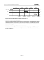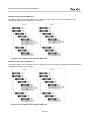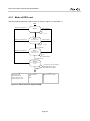
1
Technical Document FeliCa Card User's Manual Excerpted Edition Version 2.0 No. M617-E02-00 FeliCa Card User's Manual Excerpted Edition Introduction This document describes the protocol specifications and the command specifications of any contactless IC card that utilizes FeliCa technology. The purpose of this document is to provide basic information about the protocol specifications and the command specifications to customers who are engaged in the development of a Reader/Writer and application software that utilize FeliCa technology. The objects of the descriptions in this document are the FeliCa-based contactless IC cards and IC chips sold by Sony Corporation. For details of FeliCa Lite series and FeliCa Plug series, see the following website: http://www.sony.net/Products/felica/business/tech-support/index.html This document does not contain any information about the following: form factor of cards, details of security structure, platform-specific information (such as the number of available Blocks, and so on), inspection/issuance specifications, and specifications of individual products. For information about the products you are using, please contact the provider of those products. This document contains information common to mobile FeliCa IC chips. Therefore, IC card products including mobile FeliCa products are referred to as “card” in this document. This document does not describe all the functions of such chips. If you have any questions about the development of application software that is compatible with mobile FeliCa, please contact FeliCa Networks, Inc. ([email protected]). The content of this document does not guarantee the correct operation of the system with all existing or future cards. FeliCa technology refers to the following standards: • JIS X 6319-4: Specification of implementation for integrated circuit(s) cards – Part 4: High speed proximity cards • ISO/IEC 18092: Information technology – Telecommunications and information exchange between systems – Near Field Communication – Interface and Protocol-1 (NFCIP-1) • FeliCa is a contactless IC card technology developed by Sony Corporation. • FeliCa is a trademark of Sony Corporation. • All names of companies and products contained herein are trademarks or registered trademarks of the respective companies. • No part of this document may be copied, or reproduced in any form, without the prior consent of Sony Corporation. • Information in this document is subject to change without notice. • Sony Corporation assumes no liability for damages arising from, or in connection with, the use of this document. Page 3 FeliCa Card User's Manual Excerpted Edition (Blank page) Page 4 FeliCa Card User's Manual Excerpted Edition Contents 1 Overview ..................................................................................................................................... 7 1.1 Card products relevant to this publication ............................................................................................. 7 1.2 Notational conventions .......................................................................................................................... 8 2 Communication protocol ........................................................................................................... 9 2.1 Physical layer ........................................................................................................................................ 9 2.2 Data link layer...................................................................................................................................... 10 2.3 Application layer .................................................................................................................................. 11 2.3.1 Command packet ....................................................................................................................... 11 2.3.2 Response packet ....................................................................................................................... 11 2.3.3 Lists of commands ..................................................................................................................... 12 2.3.4 Manufacture ID and Manufacture Parameter ............................................................................ 14 2.3.5 Anti-collision process ................................................................................................................. 16 2.4 Start-up time and guard time............................................................................................................... 18 2.4.1 Maximum start-up time of card .................................................................................................. 18 2.4.2 Guard time ................................................................................................................................. 18 3 File system ............................................................................................................................... 20 3.1 Block .................................................................................................................................................... 23 3.2 System ................................................................................................................................................ 24 3.2.1 System Definition Information .................................................................................................... 24 3.2.2 Code to indicate System ............................................................................................................ 24 3.2.3 System Separation .................................................................................................................... 24 3.2.4 Switching between Systems ...................................................................................................... 25 3.3 Area ..................................................................................................................................................... 26 3.3.1 Area Definition Information ........................................................................................................ 27 3.3.2 Area 0 ........................................................................................................................................ 28 3.4 Service ................................................................................................................................................ 29 3.4.1 Service Definition Information .................................................................................................... 29 3.4.2 Random Service ........................................................................................................................ 31 3.4.3 Cyclic Service ............................................................................................................................ 32 3.4.4 Purse Service ............................................................................................................................ 34 3.4.5 Overlap Service ......................................................................................................................... 37 3.5 Logical hierarchical structure .............................................................................................................. 39 3.6 Protection of data ................................................................................................................................ 41 3.6.1 Data protection function against power interruption .................................................................. 41 3.6.2 Error detection function for Block Data ...................................................................................... 41 4 Commands ............................................................................................................................... 42 4.1 Acquisition and identification of cards ................................................................................................. 42 4.2 Access to Block ................................................................................................................................... 43 4.2.1 Block List and Block List Element .............................................................................................. 44 4.2.2 Example of setting up Block List ................................................................................................ 46 4.3 Mode ................................................................................................................................................... 47 4.3.1 Mode of DES card ..................................................................................................................... 48 4.3.2 Mode of AES card ...................................................................................................................... 50 4.3.3 Mode of AES/DES card ............................................................................................................. 52 4.4 Command specifications ..................................................................................................................... 54 4.4.1 Structure of descriptions ............................................................................................................ 54 4.4.2 Polling ........................................................................................................................................ 56 4.4.3 Request Service ........................................................................................................................ 59 4.4.4 Request Response .................................................................................................................... 61 4.4.5 Read Without Encryption ........................................................................................................... 62 4.4.6 Write Without Encryption ........................................................................................................... 64 4.4.7 Search Service Code ................................................................................................................. 66 Page 5 FeliCa Card User's Manual Excerpted Edition 4.4.8 Request System Code ............................................................................................................... 67 4.4.9 Authentication1 .......................................................................................................................... 68 4.4.10 Authentication2 ........................................................................................................................ 69 4.4.11 Read ........................................................................................................................................ 70 4.4.12 Write......................................................................................................................................... 71 4.4.13 Request Service v2 .................................................................................................................. 72 4.4.14 Get System Status ................................................................................................................... 74 4.4.15 Request Specification Version ................................................................................................. 75 4.4.16 Reset Mode ............................................................................................................................. 77 4.4.17 Authentication1 v2 ................................................................................................................... 78 4.4.18 Authentication2 v2 ................................................................................................................... 79 4.4.19 Read v2.................................................................................................................................... 80 4.4.20 Write v2 .................................................................................................................................... 81 4.4.21 Update Random ID .................................................................................................................. 82 4.5 Status Flag .......................................................................................................................................... 83 4.5.1 Status Flag1 ............................................................................................................................... 83 4.5.2 Status Flag2 ............................................................................................................................... 84 5 Security..................................................................................................................................... 86 6 Inspection ................................................................................................................................. 87 7 Issuance ................................................................................................................................... 88 Appendix A FeliCa Terminology ................................................................................................ 89 A.1 Abbreviations ...................................................................................................................................... 89 A.2 Glossary .............................................................................................................................................. 89 Page 6 FeliCa Card User's Manual Excerpted Edition 1 Overview Chapter 1(this chapter) describes the general structure of this document, card products relevant to this publication, reference documents, and notational conventions. Chapter 2 describes the communication protocol of FeliCa technology. Chapter 3 describes the file system of FeliCa card. Chapter 4 describes the general commands used by FeliCa card. This document does not describe the detailed specifications of any security-related commands. Chapter 5, Chapter 6, and Chapter 7 are placeholders for FeliCa card security, inspection, and issuance specifications, all of which are beyond the scope of this document. 1.1 Card products relevant to this publication This document covers the following IC card products: • DES card This type of card supports only the DES encryption mechanism. • AES card This type of card supports only the AES encryption mechanism. • AES/DES card This type of card supports both the AES encryption mechanism and the DES encryption mechanism. The commands supported by each of these products can differ, depending on the type of card being used. For details of the commands supported by each card type, see Table 2-4. The AES encryption mechanism explained in this document has a key length of 128 bits. Page 7 FeliCa Card User's Manual Excerpted Edition 1.2 Notational conventions This section describes the notation used in this document. The following notational conventions apply in this document, unless otherwise specified: Binary values "b" is appended to a binary value (e.g., 0101b). Hexadecimal values "h" is appended to a hexadecimal value (e.g., FFFFh). Decimal values Nothing is appended to a decimal value (e.g., 10). Bit notation Bits are denoted in sequence from most-significant-bit (MSB) on the left to least-significant-bit (LSB) on the right. ALL_Xb Denotes all bits (e.g., ALL_0b, where all bits are 0b). ALL_XXh Denotes all Bytes (e.g., ALL_FFh, where all Bytes are FFh). Byte order Big Endian, unless otherwise specified. In figures, Byte strings and bit strings are denoted as shown in Figure 1-1, Figure 1-2, and Figure 1-3. Byte string D0 D1 D2 D4 D3 ... Dn Figure 1-1: Graphic notation of Byte string Each Byte MSB b7 LSB b6 b5 b3 b4 b2 b1 b0 Figure 1-2: Graphic notation of bit string D0 b7 b6 b5 b4 D1 b3 b2 b1 b0 b7 b6 b5 b4 b3 Dn b2 b1 b0 D4 ... b7 b6 b5 b4 b3 b2 b1 b0 Figure 1-3: Graphic notation of Byte string and bit string When referring to specific Bytes or bit in figures, the following notation is used: upper 2 Bytes Indicates 2 Bytes, from D0 to D1, inclusive. Unless otherwise specified, D0 is the most significant Byte. D0-D15 Indicates 16 Bytes from D0 to D15, inclusive. upper 6 bits Indicates 6 bits from b7 to b2, inclusive. b5-b3 Indicates 3 bits from b5 to b3, inclusive. Page 8 FeliCa Card User's Manual Excerpted Edition 2 Communication protocol This chapter describes the communication protocol used for communication with cards and is organized as follows: • Physical layer This layer defines the physical and electrical characteristics of data transfer. • Data link layer This layer defines the data transfer method and the error detection scheme. • Application layer This layer defines the specifications and functions of data strings to be handled as commands. • Start-up time and guard time "Maximum start-up time" and "guard time" of card are defined in this chapter. 2.1 Physical layer Table 2-1 shows the transmission characteristics of the physical layer of RF communication with cards. Table 2-1: Transmission characteristics of physical layer of RF communication interface Item Description Data transfer method Carrier frequency (fc) Modulation method Bit coding Data transfer rate Half duplex, synchronous system 13.56 MHz ASK Manchester code, MSB first fc / 64 (approximately 212 kbps); hereinafter 212 kbps fc / 32 (approximately 424 kbps); hereinafter 424 kbps Depending on the type of card being used, the supported data transfer rate can differ. Details of the data transfer rate supported by a card can be acquired with the Polling command. For details of the Polling command, see section 4.4.2 "Polling". Page 9 FeliCa Card User's Manual Excerpted Edition 2.2 Data link layer Data transfer between the Reader/Writer and the card is performed on a packet-by-packet basis, as defined in the data link layer. For definitions of fields in a packet and the packet structure, see Table 2-2 and Figure 2-1. Table 2-2: Definition of fields in a packet Field Name Byte length Definition Preamble Sync code Data length (LEN) Packet Data 6 2 1 n CRC 2 (00 00 00 00 00 00)h (B2 4D)h Value of n (Byte length of Packet Data) + 1 (Byte length of LEN) Command Packet Data or Response Packet Data (to be defined on a command-by-command basis) Checksum of data length and Packet Data, based on CRC-CCITT (Big Endian) Initial value: 00 00h 16 12 5 Generator polynomial: X + X + X + 1 (LEN + 10) Byte (LEN) Byte 1 Byte \ \ 00 \ \ 00 B2 4D LEN PD0 PD1 \ \ PDn-1 \ \ CRC CRC Packet Data Data length Sync code Preamble Figure 2-1: Packet structure Page 10 FeliCa Card User's Manual Excerpted Edition 2.3 Application layer This section describes the rules applied to Packet Data (i.e., the data contained in a packet). It also describes the rules that govern how the parameters contained in Packet Data are processed in accordance with the communication protocol. In this document, Packet Data received by the card is known as a command packet, and Packet Data transmitted from the card is known as a response packet. 2.3.1 Command packet A command packet consists of Command Code (i.e., the first Byte) followed by command data. 1 Byte PD0 PD1 \ \ \ \ PDn-1 Command data Command Code Figure 2-2: Command packet • Command Code Command Code identifies the type of command. For an overview of available commands and their associated Command Code and Response Code, see Table 2-3. • Command data The command data are defined on a command-by-command basis. For information about the contents to be defined, see section 4.4 "Command specifications”. 2.3.2 Response packet A response packet consists of Response Code (i.e., the first Byte) and response data. 1 Byte PD0 PD1 \ \ \ \ PDn-1 Response data Response Code Figure 2-3: Response packet • Response Code Response Code identifies the type of response. • Response data The response data are defined on a command-by-command basis. For information about the contents to be defined, see the command descriptions in 4.4 "Command specifications”. Page 11 FeliCa Card User's Manual Excerpted Edition 2.3.3 Lists of commands Table 2-3 lists card common commands and their Command Code and Response Code. For details of the commands supported by each card type, see Table 2-4. For detailed information about each of these commands, see section 4.4 "Command specifications”. The abbreviations used in Table 2-3 are explained as follows: • CC: Command Code • RC: Response Code • DES: DES-encrypted secure communication • AES: AES-encrypted secure communication Table 2-3: Common commands Command name CC RC Function overview Encryption Polling 00h 01h Use this command to acquire and identify a card. No Request Service 02h 03h No Request Response 04h 05h Read Without Encryption Write Without Encryption Search Service Code 06h 07h 08h 09h 0Ah 0Bh Use this command to verify the existence of Area or Service, and to acquire Key Version. Use this command to verify the existence of a card and its Mode. Use this command to read Block Data from authentication-not-required Service. Use this command to write Block Data to authentication-not-required Service. Use this command to acquire Area Code and Service Code. Request System Code 0Ch 0Dh No Authentication1 10h 11h Use this command to acquire System Code registered to the card. Use this command to authenticate a card. Authentication2 12h 13h DES Read 14h 15h Write 16h 17h Request Service v2 32h 33h Get System Status 38h 39h Request Specification Version Reset Mode 3Ch 3Dh Use this command to allow a card to authenticate a Reader/Writer. Use this command to read Block Data from authentication-required Service. Use this command to write Block Data to authentication-required Service. Use this command to verify the existence of Area or Service, and to acquire Key Version. Use this command to acquire the setup information in System. Use this command to acquire the version of card OS. 3Eh 3Fh Use this command to reset Mode to Mode0. No Authentication1 v2 40h 41h Use this command to authenticate a card. No Authentication2 v2 42h 43h AES Read v2 44h 45h Write v2 46h 47h Update Random ID 4Ch 4Dh Use this command to allow a card to authenticate a Reader/Writer. Use this command to read Block Data from authentication-required Service. Use this command to write Block Data to authentication-required Service. Use this command to update Random ID (IDr). Page 12 No No No No No *1 DES DES No No No AES AES AES *2 FeliCa Card User's Manual Excerpted Edition *1, *2 Only the response is encrypted. Table 2-4: Commands supported by each card type Command name DES card AES card AES/DES card Polling Request Service Request Response Read Without Encryption Write Without Encryption Search Service Code Request System Code Authentication1 Authentication2 Read Write Request Service v2 Get System Status Request Specification Version Reset Mode Authentication1 v2 Authentication2 v2 Read v2 Write v2 Update Random ID Y Y Y Y Y Y Y Y Y Y Y N N N N N N N N N Y Y Y Y Y Y Y N N N N Y Y Y Y Y Y Y Y Y Y Y Y Y Y Y Y Y Y Y Y Y Y Y Y Y Y Y Y Y Legend: • Y: supported command • N: unsupported command Page 13 FeliCa Card User's Manual Excerpted Edition 2.3.4 Manufacture ID and Manufacture Parameter This section describes Manufacture ID (IDm) and Manufacture Parameter (PMm). IDm and PMm can be acquired as the response data to the Polling command. Figure 2-4 shows the configuration of IDm and PMm. All the setting values are defined per product. IDm D0 D1 D2 D3 PMm D4 D5 D6 D7 D8 D9 D10 D11 D12 D13 D14 D15 Maximum response time parameters IC Code (D8: ROM Type, D9: IC Type) Card Identification Number Manufacturer Code Figure 2-4: IDm and PMm • Manufacture ID (IDm) Using Manufacture ID (IDm), the Reader/Writer identifies a card to be the counterpart of communication. If more than one System exists on a card, IDm is set to each such System. As shown in Figure 2-4, IDm consists of Manufacturer Code and Card Identification Number. The upper 4 bits of the 1 Byte of data located at the top of Manufacturer Code indicate System Number in the card. System Number is automatically incremented by one in the order of separation of System. The upper 4 bits of IDm of System 0 is 0000b, so (for example), the upper 4 bits of IDm of System 1 becomes 0001b. For details of System, see section 3.2 "System". • Manufacture Parameter (PMm) As shown in Figure 2-4, PMm consists of IC Code (2 Bytes) and the maximum response time parameters (6 Bytes). o IC Code (2 Bytes) This is the information to identify a product. IC code consists of two components, i.e., ROM Type and IC Type. o Maximum response time parameters (6 Bytes) The timeout time is determined, based on the period of time necessary to process the commands. Therefore (and because this period of time depends on the status of the card, and on the type and content of each command), the Reader/Writer shall dynamically determine the timeout time. In FeliCa technology, the maximum response time is determined by using the lower 6 Bytes of PMm. The card provides this parameter to the Reader/Writer, enabling the Reader/Writer to dynamically determine the timeout time. The meaning of each Byte of PMm and the supported command groups are listed in Table 2-5. Page 14 FeliCa Card User's Manual Excerpted Edition Table 2-5: Description and the corresponding command of each Byte of PMm Position Command type Command name Meaning of n in calculation formula D10 Command for which the response time varies, depending on the packet element Command for which the response time is fixed Request Service Request Service v2 Number of Node Number of Node Request Response Search Service Code Request System Code Get System Status Request Specification Version Reset Mode Update Random ID Authentication1 Authentication2 Authentication1 v2 Authentication2 v2 Read Without Encryption Read Read v2 Write Without Encryption Write Write v2 (Issuance commands) 0 0 0 0 0 D11 D12 Command for mutual authentication D13 Command for data read D14 Command for data write D15 Other commands 0 0 Number of Node 0 Number of Node 0 Number of Block Number of Block Number of Block Number of Block Number of Block Number of Block 0 As shown in Figure 2-5, each Byte in the maximum response time parameter consists of an exponential part (E) (2 bits) and two real parts (A) and (B) (3 bits each). Byte of maximum response time parameter b7 b6 b5 b4 b3 b2 b1 b0 Real part(A) Real part(B) Exponential part(E) Figure 2-5: Maximum response time parameter The Reader/Writer references the 1 Byte in PMm corresponding to each command, and then determines the maximum response time in accordance with the following calculation formula (additionally, acquisition of PMm is made possible by the Polling command): E Maximum Response Time (ms) = T × [(B+1) × n + (A+1)] × 4 T = 256 × 16 / fc (approximately 0.3020 ms) where the value of n is as shown in the "Meaning of n in calculating formula" column in Table 2-5. In a card, the process time of each command is measured, based on the definition of intervals shown in Figure 2-6, and the value of the maximum response time is determined. Note that the processing time of other commands in Table 2-5 may exceed the maximum response time depending on the product being used. For the Polling command, a response time different from the ones for the other commands are defined. For details, see section 2.3.5 "Anti-collision process”. Page 15 FeliCa Card User's Manual Excerpted Edition (1) Preamble Sync code Command (2) Preamble CRC Sync code Response CRC Time t Maximum response time (1) The point in time when transmission of all data in the command packet from the Reader/Writer is completed (2) The point in time when transmission of the Sync code in the response packet from the card is completed Figure 2-6: Definition of maximum response time 2.3.5 Anti-collision process To identify a card, the Reader/Writer shall poll an unspecified number of cards, by using the Polling command. If two or more cards exist within the range where communication between the Reader/Writer and the cards is possible, and if these cards respond to the Polling command simultaneously, however, the Reader/Writer is unable correctly to receive the responses returned from the cards. Therefore, FeliCa technology adopts a method known as the time-slot method, to reduce the probability of collision between the responses returned simultaneously from two or more cards. • Time-slot method Sections on the time axis divided at regular intervals are known as "time slots". Both the Reader/Writer and the card have the same number of (i.e., "n") time slots, and these slots are mutually synchronized. When the Polling command is received, the card selects a time slot in a random manner and then transmits a response to the Polling command only in the selected slot. When the Reader/Writer polls cards under the previously-mentioned assumptions, it is expected that the cards return responses to the polling in a random manner in each time slot. This reduces the probability of collision between responses to the Polling command sent to two or more cards. In FeliCa technology, the start time of the first time slot is known as "Response time (A)", and the width (i.e., duration) of the time slot is known as "Response time (B)". These response times are defined as follows: o Response time (A) 512 x 64 / fc (approximately 2.417 ms) o Response time (B) 256 x 64 / fc (approximately 1.208 ms) The number of time slots (i.e., "n") to be shared between the Reader/Writer and the card is specified by the Polling command. For details, see section 4.4.2 "Polling". Figure 2-7 shows an example of response times of the cards to the Polling command where the number of time slots is "4", and there are two cards within communication range of the Reader/Writer. This diagram shows the case where card 1 selected slot #1 and card 2 selected slot #3 of four time slots specified by the Reader/Writer. Page 16 FeliCa Card User's Manual Excerpted Edition Time slot #0 1.208 [ms] 2.417 [ms] Reader / Writer Time slot #1 1.208 [ms] Time slot #2 1.208 [ms] Time slot #3 1.208 [ms] Polling command Time t Polling Response Card 1 Time t Polling Response Card 2 Response time (A) Response time (A) + Response time (B) × 1 Response time (A) + Response time (B) × 2 Response time (A) + Response time (B) × 3 Time t Response time (A) + Response time (B) × 4 Figure 2-7: Response time (where the number of time slots = 4) • Identification of communication target by IDm When a response packet to the Polling command is correctly received, the Reader/Writer acquires IDm contained in the response packet. By setting IDm to the command packet, communication with a specific card becomes possible, even when two or more cards exist. At the time a command packet is received, each card references IDm. If the command packet is not the one addressed to the card itself, the card does not return a response. • Identification of communication target in secure communication In any command to be encrypted, IDm is not set to the command packet. While decrypting the received command packet, each card checks the message authentication code (MAC) to confirm whether the command packet is encrypted with the correct key for the card itself. If the MAC is incorrect, the card does not return a response. Page 17 FeliCa Card User's Manual Excerpted Edition 2.4 Start-up time and guard time 2.4.1 Maximum start-up time of card When a card enters the magnetic field generated by a Reader/Writer, the card activates the IC chip in the card. After performing the initialization process, the card transitions to a state that can receive commands transmitted from the Reader/Writer. The maximum start-up time of the card is the maximum period of time required from the start-up of the IC chip in the card until the reception of a command becomes possible. The maximum start-up time of the card is defined by the following formula: Maximum start-up time of card = 20 ms Considering the start-up time of the magnetic field, it is recommended that the Reader/Writer continues generating the magnetic field for a period of time of at least 20.4 ms. Thereafter, the Reader/Writer can transmit the Polling command. Although the Reader/Writer may transmit the Polling command before the 20.4 ms period has elapsed, it is recommended to retry the transmission of the Polling command, while considering the case where no response is returned from the card. 2.4.2 Guard time • Guard time of card The guard time of a card is the period of time starting when transmission of all the Response Packet Data to a command (excluding the Polling command) from the card completed until the point in time when the Reader/Writer starts transmitting the top data of the preamble of the next command packet (see Figure 2-8). For the Polling command, the starting point is immediately after the maximum response time to the Polling command (see Figure 2-9) has elapsed. After returning a response, the card transitions to the "waiting for a command sent from Reader/Writer" state for a period of time not exceeding 106 x 64 / fc (approximately 500 µs). As shown in Figure 2-10, after receiving a response from a card, it is recommended that the Reader/Writer (i.e., application) waits at least (106 x 64 + 16) / fc (approximately 501 µs) until it transmits the next command. Start point Preamble Sync code Response Preamble CRC Guard time of card Figure 2-8: Guard time of card Page 18 Sync code Command CRC Time t FeliCa Card User's Manual Excerpted Edition Start point Preamble Sync code Command CRC ・ ・ ・ ・ ・ ・ Polling command Preamble Time slot frame time (#N-1) 256×64/fc Time slot frame time (#N) 256×64/fc Guard time of card Sync code Command CRC Time t Command Figure 2-9: Guard time of card (Polling command) Reader/Writer Card Command A Reader/Writer enters into "waiting a response" state not exceeding 197 µs. Response A After received a response, Reader/ Writer waits at least 501 µs before transmission of next command. Command B Figure 2-10: Guard time of Reader/Writer and card • Guard time of Reader/Writer After receiving a command from the Reader/Writer, the card transmits a response after a period of time of at least 42 x 64 / fc (approximately198 µs) has elapsed (see Figure 2-11). It is recommended that the Reader/Writer transitions to a "waiting a response from a card" state for a period of time not exceeding (42 x 64 - 16) / fc (approximately 197 µs) after the transmission of a command (see Figure 2-10). Start point Preamble Sync code Command Preamble CRC Guard time of Reader/Writer Figure 2-11: Guard time of Reader/Writer Page 19 Sync code Response CRC Time t FeliCa Card User's Manual Excerpted Edition 3 File system This chapter explains the concept of the FeliCa file system. The FeliCa file system consists of four components, that is, System, Area, Service, and Block Data. These components are managed together as a unit of specific data size, known as a "Block". Service determines the access methods and access rights to Block Data, and then stores an authentication key to authenticate the access rights. In some Service access methods, Block Data can be read or written without using this authentication key. In the other access methods to Service, however, Block Data cannot be read or written without successful mutual authentication between a card and a Reader/Writer using this authentication key. Area is the concept for the hierarchical management of Block Data. Areas can be structured in a hierarchical manner. Each Area located in a lower level of hierarchy is known as Sub-Area. Each Area located in a higher level of hierarchy from another Area is known as Parent Area. Each Area is authorized to create Sub-Area, to register Service, and to change keys. A single physical card can store two or more logical cards. Each of these logical cards is known as System. System created first, at the time of card manufacture, is known as "System 0". From System 0, "System 1" can be created, then "System 2", and so on in ascending order. In this document, System, Area, and Service are known collectively as Node. Page 20 FeliCa Card User's Manual Excerpted Edition Example of file system of DES card As shown in Figure 3-1, each System, Area, or Service is able to store only the key required for DES authentication (hereinafter referred to as "DES key"). Figure 3-1: An example of file system of DES card Example of file system of AES card As shown in Figure 3-2, each System, Area, or Service can store only the key required for AES authentication (hereinafter referred to as "AES key"). Figure 3-2: An example of file system of AES card Page 21 FeliCa Card User's Manual Excerpted Edition Example of file system of AES/DES card As shown in Figure 3-3, each System, Area, or Service can store two types of keys, i.e., AES key and DES key. Key Version of AES key can differ from Key Version of DES key. Figure 3-3: An Example of file system of AES/DES card For AES/DES card, if both AES key and DES key are assigned to Service, Block Data of Service can be accessed using either the AES encryption mechanism or the DES encryption mechanism. When System, Area, or Service is generated, only AES key, only DES key, or both keys are assigned to each of them. Nevertheless, only AES key or both keys shall be assigned to System and Area 0. A child level of the hierarchy (Area or Service) can store any key from the encryption type assigned to the parent level of the hierarchy (System or Area) located directly above it. For example, when Parent Area contains both AES key and DES key, Area or Service located under Parent Area can store both keys, only AES key, or only DES key. Page 22 FeliCa Card User's Manual Excerpted Edition 3.1 Block In the process of writing data to or reading data from memory, each 16-Byte unit is known as Block. All the user data are stored to Block. Access to the memory space from the user is performed on a Block-by-Block basis. Therefore, it is necessary to divide the data into multiple Block to store user’s data exceeding 16 Bytes. In addition to user’s data, the management information of the file system and so on is stored in Block. All the management of Block located in non-volatile memory space is performed by the file system. Therefore, the user does not need to perform any direct operation on Block, which is accessed by using a mechanism known as Area or Service. Block 16 Bytes ・ ・ ・ ・ ・ User Block (Accessible via Service) ・ ・ Block provided by a card ・ ・ ・ ・ Management Block by file system (Not accessible) Non-volatile Memroy Figure 3-4: Blocks in non-volatile memory Page 23 FeliCa Card User's Manual Excerpted Edition 3.2 System "System" is the normative unit to be handled as a logical card. In a physical card, it is possible to create more than one System with the procedure known as System Separation (see Figure 3-3). Each System is separated in their functionality and security, and there is no interference between them. 3.2.1 System Definition Information System Definition Information is the information concerning System. System Definition Information contains the following information: System Code System Code is used by the Reader/Writer to identify a card (System). When identifying a card, the Reader/Writer shall poll an unspecified number of cards with the Polling command. In this case, System Code is specified as the parameter of the Polling command, and System returns a response only when its System Code matches System Code in the parameter of the Polling command at a preliminary stage of the anti-collision process. Even if System of a card is divided, the Reader/Writer identifies each System as a single card unit. Therefore, the Reader/Writer can capture the destination System by specifying any System Code from System 0 to System n in the Polling command. Issue ID information Issue ID information is the information recorded to a card at the time of its issuance. The card issuer can set any data to this information. System Key This is the value of the key assigned to System. System Key Version This is the value to be used to identify System Key assigned to System. 3.2.2 Code to indicate System The code used to indicate System is FFFFh. This code is used to acquire System Key Version using the Request Service command or the Request Service v2 command. This code is also used to perform mutual authentication including System using the Authentication1 command or the Authentication1 v2 command. 3.2.3 System Separation At the time of card manufacture, only System 0 exists. System Separation creates a new System. Each new System created during System Separation is named as "System 1", "System 2", … "System n", in ascending chronological order of their creation. As shown in Figure 3-5, the number of Blocks required for the new System is assigned from the number of remaining Blocks in Area 0 of System 0. Page 24 FeliCa Card User's Manual Excerpted Edition System 1 System 1 To be assigned from System 0 System 0 System 2 System Separation System 0 Figure 3-5: Concept of Block assignment The maximum number of System Separation instances supported by the product can differ, depending on the product being used. For details of this maximum number, see the specifications of the product you are using. 3.2.4 Switching between Systems In FeliCa technology, a function that “destination System of command packet returns a response in place of System currently active” is available. Even when System (i.e., System A) received a command packet addressed to the other System (i.e., System B) existing on the card, this function causes System B to return a response instead of System A. This is known as “Switching between Systems”. When “Switching between Systems” occurs, Mode of the card transitions to Mode0 and mutual authentication status is cancelled. If Switching between Systems is executed successfully by either the Authentication1 command or the Authentication1 v2 command, however, Mode of the card becomes Mode1. The following two methods are available to perform Switching between Systems: • Switching between Systems by using the Polling command: Select System by specifying System Code of System you want to switch to the parameter of the Polling command. • Switching between Systems by specifying IDm: Select System using a command that includes IDm in the parameter of the command packet. In this case, set the value of IDm you want to switch to IDm of the command packet. Page 25 FeliCa Card User's Manual Excerpted Edition 3.3 Area The concept of Area is used in the management of the remaining usable Block in non-volatile memory space or of assignment of Block to Service. Each Service is managed by any Area. So when Service is registered, each Block to be managed by that Service is assigned from another Block managed by Area. It is also possible to manage instances of Area nested inside one another. This allows Block managed by a specific Area to be assigned to and be managed by another Area. Area A Block Number Block 0 Service A 1 Service A 2 0 Number of blocks is managed by Area A 1 Service B 2 Service B 3 4 0 Area B 1 Service C 2 3 Service C Number of blocks is managed by Area B * * Unused * * Non-volatile Memory Figure 3-6: Concept of management of Block by Area Page 26 FeliCa Card User's Manual Excerpted Edition 3.3.1 Area Definition Information This is the information used to define each Area. It is stored per Area and contains the following information: Area Code This is the code used to identify Area. As shown in Figure 3-7, Area Code is 2 Bytes of data consisting of Area Number and Area Attribute. D1 (Upper Byte) b7 b6 b5 b4 b3 b2 D0 (Lower Byte) b1 b0 b7 b6 b5 b4 b3 b2 b1 b0 Area Attribute Area Number Figure 3-7: Structure of Area Code Area Number is the value to be arbitrarily set by the registrant of Area. In any Sub-Area, however, Area Number shall be set in the range greater than or equal to Area Number of Parent Area and less than or equal to End Service Code of Parent Area. Area Attribute is the value indicating whether Sub-Area can be created under Area. The value of Area Attribute shall be either 000000b or 000001b, as shown in the following table: Table 3-1: Area Attribute Area Attribute Area type 000000b 000001b Area that can create Sub-Area. Area that cannot create Sub-Area. End Service Code This is the code used for specifying the maximum value of Service Code that can be registered under Area. Number of assigned Blocks This is the number of Blocks assigned to the region managed by Area. Sub-Area or Service can be created within the range of this number of Blocks. Area Key This is the value of the key assigned to Area. Area Key is used, for example, for the creation of Sub-Area, the creation of Service, and the change of keys for Sub-Area and Service under Area. Area Key Version This is the value used to identify Area Key being set. Page 27 FeliCa Card User's Manual Excerpted Edition 3.3.2 Area 0 The relationship between Area and Service is the logical hierarchical structure shown in Figure 3-3. Area to be the root of this hierarchical structure is known as Area 0. Area 0 is located at the highest level of hierarchy, and it always exists in System. Area Code of Area 0 is 0000h, and End Service Code is FFFEh. Page 28 FeliCa Card User's Manual Excerpted Edition 3.4 Service Service is a group of Block located on the file system. Service provides access control to Blocks so grouped. All access to each such Block is performed by using Service. Therefore, access to Block in non-volatile memory becomes possible by registration of Service to the file system. To access each Block being managed by any Service, first identify Service with a 2-Byte code known as Service Code. Then, by using a 2-Byte number known as Block Number, specify any Block located in the range being managed by Service specified by Service Code. Block Number starts from zero (“0”) within Service. Block Block Number Block Number 0 Service Code Service A Block Number 2 Service Code Service B 0 AA AA AA ・・・ AA 1 BB BB BB ・・・ BB 2 CC CC CC ・・・ CC 0 AA AA AA ・・・ AA 1 BB BB BB ・・・ BB 2 CC CC CC ・・・ CC 3 DD DD DD ・・・ DD 4 EE EE EE ・・・ EE A group of blocks managed by Service A A group of blocks managed by Service B Non-volatile Memory Figure 3-8: Concept of access to Block by Service 3.4.1 Service Definition Information Information to define each Service contains the following information: Service Code This is the code used to identify Service. Service Code is 2-Byte data in which Service Number and Service Attribute are aligned in this order. Configuration of Service Code is as shown in Figure 3-9. Service Number is the value to be arbitrarily set by the registrant of the service, and it shall have a value in the range of Area Number and End Service Code of Parent Area. Service Attribute is the lower 6 bits of Service Code. This value determines control of access to Block Data. Values of Service Attribute are as listed in Table 3-2. D0 (Lower Byte) D1 (Upper Byte) b7 b6 b5 b4 b3 b2 b1 b0 b7 b6 b5 b4 b3 b2 b1 b0 Service Attribute Service Number Figure 3-9: Structure of Service Code Page 29 FeliCa Card User's Manual Excerpted Edition Table 3-2: Service Attribute Service Attribute Random Service Cyclic Service Purse Service Value Read/Write Access: authentication required Read/Write Access: authentication not required Read Only Access: authentication required Read Only Access: authentication not required Read/Write Access: authentication required Read/Write Access: authentication not required Read Only Access: authentication required Read Only Access: authentication not required Direct Access: authentication required Direct Access: authentication not required Cashback Access/Decrement Access: authentication required Cashback Access/Decrement Access: authentication not required Decrement Access: authentication required Decrement Access: authentication not required Read Only Access: authentication required Read Only Access: authentication not required 001000b 001001b 001010b 001011b 001100b 001101b 001110b 001111b 010000b 010001b 010010b 010011b 010100b 010101b 010110b 010111b Number of assigned Blocks This is the number of Blocks assigned to Service. This number indicates the range of access of Service (Block Number: 0 to Number of Block - 1). Service Key This is the value of the key assigned to Service. Service Key Version This is the value used to identify Service Key being set. Page 30 FeliCa Card User's Manual Excerpted Edition 3.4.2 Random Service Random Service is a general-purpose service that allows access to Block specified at the discretion of the user. Service Attribute Random Service has four types of Service Attributes, as shown in the following table: Table 3-3: Service Attribute of Random Service Service Attribute Read/Write Access: Authentication required Read/Write Access: Authentication not required Read Only Access: Authentication required Read Only Access: Authentication not required Read Write Y Y Y Y Y Y N N Authentication of Service Necessary Unnecessary Necessary Unnecessary Structure of Block Any data can be stored in Block. D0 D1 D2 D3 D4 D5 D6 D7 D8 D9 D10 D11 D12 D13 D14 D15 Any value of data Figure 3-10: Structure of Block in Random Service Specifying Block Block can be specified by using Block Number (see Figure 3-11). Any Block Numbers can by specified Service Code Random Service Block Data 0 AA AA AA ・・・ AA 1 BB BB BB ・・・ BB 2 CC CC CC ・・・ CC 3 DD DD DD ・・・ DD 4 EE EE EE ・・・ EE Non-volatile Memory Figure 3-11: Specifying Block in Random Service Page 31 A group of blocks managed by a Random Service FeliCa Card User's Manual Excerpted Edition 3.4.3 Cyclic Service Cyclic Service provides a special function when accessing Block associated with the “recording of logs” as the use case. In each case, data is written to Block containing the oldest data. This method of data writing enables cyclic use of a group of Block. While new data automatically and sequentially overwrites the oldest data first, there is a risk of unintentional loss of existing data if the same data is repeatedly and indiscreetly written. To prevent this occurring, Cyclic Service has a function that compares the oldest data in the target Block with the data to be written. If both sets of data are identical, the command completes normally but the data in the target Block is not updated. In a card, a single command can be used to write data simultaneously to more than one Block. In this case, each Block is handled as an independent data unit. In Cyclic Service, however, when sequential data is written to the same Cyclic Service, such sequential Block Data are grouped together and handled as a single unit of data, with the following consequences: • Data comparison to determine identity at the time of data writing is performed between such groups of sequential Block Data, not between the data in each Block. • If the newly-grouped Block Data completely matches any older data that are stored in more than one Block, the older data are not updated. • Even if a data log is not stored within a single Block but distributed over several Block, the risk of unintentional loss of existing data can be avoided. Service Attribute In Cyclic Service, four types of Service Attribute are provided, as listed in the following table: Table 3-4: Service Attribute of Cyclic Service Service Attribute Read/Write Access: Authentication required Read/Write Access: Authentication not required Read Only Access: Authentication required Read Only Access: Authentication not required Read Write Y Y Y Y Y Y N N Authentication of Service Necessary Unnecessary Necessary Unnecessary Structure of Block Any data can be stored in Block. D0 D1 D2 D3 D4 D5 D6 D7 D8 D9 D10 D11 D12 D13 D14 D15 Any value of data Figure 3-12: Structure of Block in Cyclic Service Specifying Block When reading data, it is possible to specify any Block Number (see Figure 3-13). In Cyclic Service, the latest data is read from Block when Block Number is "0". It is possible to read the older data by increasing the value of Block Number. Page 32 FeliCa Card User's Manual Excerpted Edition Any Block Numbers can be specified Service Code Block Data Cyclic Service 0 AA AA AA ・・・ AA 1 BB BB BB ・・・ BB 2 CC CC CC ・・・ CC 3 DD DD DD ・・・ DD 4 EE EE EE ・・・ EE Latest data Oldest data Non-volatile Memory Figure 3-13: Specifying Block in data read operation during Cyclic Service When writing data, in each case it is necessary always to specify "0" to Block Number(see Figure 3-14). In Cyclic Service, the oldest data at that time is automatically overwritten by the new data, and the group of Block is used in a cyclic manner. It is impossible to specify the target Block when writing data. Block Data Block Nubmer is always 0 Service Code Cyclic Service 0 AA AA AA ・・・ AA 1 BB BB BB ・・・ BB 2 CC CC CC ・・・ CC 3 DD DD DD ・・・ DD 4 EE EE EE ・・・ EE Latest data Oldest data Non-volatile Memory Figure 3-14: Specifying Block in data write operation during Cyclic Service Page 33 FeliCa Card User's Manual Excerpted Edition 3.4.4 Purse Service Purse Service provides a function to decrement a value from Block Data, a part of which is regarded as a positive numerical value. Purse Service provides this special function when accessing Block associated with fee collection as a use case. For each Block under the management of this Service, the fields are defined as shown in Table 3-5. For the data stored to each field, it is possible to automatically perform numeric operations at the time of access using the functions described in the following list. Block List Element is used to specify an operation function. • Decrement function With this function, the purse data is decremented by the specified value. At the same time, the value so decremented is stored in cashback data. The value to be decremented is specified by Block Data to be written. • Cashback function Up to a ceiling of the value stored in cashback data, the specified value is added to purse data (i.e., cashback). When a cashback operation is performed, the cashback data is reset to zero ("0"), regardless of the value added to the purse data. The value to be added to the purse data is specified by Block Data to be written. In addition, a parameter known as Execution ID is available in Purse Service. During Purse Service operation, this parameter compares the Execution ID of Block Data to be written and the Execution ID of the target Block Data. If Execution ID of both these Block Data is identical, the data write command completes normally without performing an update (such as decrement, increment, and so on) of Block Data. This function prevents the data from being repeatedly decremented, even if a command requesting data to be written to the same Purse Service was retransmitted due to communication errors or any other problem. Table 3-5: Fields of Block in Purse Service Field Description Purse data Cashback data User data Execution ID This is the field to store data (such as remaining value, and so on). This is the field to store the value decremented from purse data. This is the field possible to store any of data. This is the field to store the Execution ID when Block was updated. Service Attribute Purse Service has eight types of Service Attributes as shown in the following table: Table 3-6: Service Attribute of Purse Service Service Attribute Decrement function Cashback function Authentication of Service Direct Access: Authentication required Direct Access: Authentication not required Cashback Access/Decrement Access: Authentication required Cashback Access/Decrement Access: Authentication not required Decrement Access: Authentication required Decrement Access: Authentication not required Read Only Access: Authentication required Read Only Access: Authentication not required N N Y Y Y Y N N N N Y Y N N N N Necessary Unnecessary Necessary Unnecessary Necessary Unnecessary Necessary Unnecessary In Purse Service, the data structure of Block to which data is written is defined per Service Attribute. For each Block structure, see Table 3-7. Page 34 FeliCa Card User's Manual Excerpted Edition Table 3-7: Block structure and Execution ID of Purse Service Service Attribute Block structure in data read Block structure in data write Execution ID Direct Access: Authentication required See Figure 3-15 See Figure 3-15 N Direct Access: Authentication not required See Figure 3-15 See Figure 3-15 N Cashback Access/Decrement Access: Authentication required Cashback Access/Decrement Access: Authentication not required Decrement Access: Authentication required See Figure 3-15 Y See Figure 3-15 See Figure 3-16 or Figure 3-17 See Figure 3-16 or Figure 3-17 See Figure 3-16 Decrement Access: Authentication not required See Figure 3-15 See Figure 3-16 Y Read Only Access: Authentication required See Figure 3-15 – – Read Only Access: Authentication not required See Figure 3-15 – – See Figure 3-15 Y Y Legend: • In the "Block structure in data write" and "Execution ID" columns, "–" indicates read-only Service. • In the "Execution ID" column, "Y" indicates that comparison of Execution ID is done before data is written. If both instances of Execution ID being compared are identical, data is not written. • In the "Execution ID" column, "N" indicates that comparison of Execution ID is not done and data is written. Structure of Block Data types that can be stored and the store method of data differ, depending on Service Attribute. Note that the cashback data and the purse data set to Block Data are in Little Endian format. D0 D1 D2 D3 D4 D5 D6 D7 D8 D9 D10 D11 D12 D13 D14 D15 Execution ID User data Cash-back data ≪Little Endian≫ Purse data ≪Little Endian≫ Figure 3-15: Block Data in Direct Access (data read) D0 D1 D2 D3 D4 D5 D6 D7 D8 D9 D10 D11 D12 D13 D14 D15 Execution ID Don’t care (Not used) Decrement value ≪Little Endian≫ Figure 3-16: Block Data when used decrement function Page 35 FeliCa Card User's Manual Excerpted Edition D0 D1 D2 D3 D4 D5 D6 D7 D8 D9 D10 D11 D12 D13 D14 D15 Execution ID Don’t care (Not used) Cash-back value ≪Little Endian≫ Figure 3-17: Block Data when used cashback function Specifying Block It is possible to specify Block, by using any Block Number (see Figure 3-18). Any Block Numbers can be specified Service Code Block Data Purse Service 0 AA AA AA ・・・ AA 1 BB BB BB ・・・ BB 2 CC CC CC ・・・ CC 3 DD DD DD ・・・ DD 4 EE EE EE ・・・ EE Non-volatile Memory Figure 3-18: Specifying Block in Purse Service Page 36 FeliCa Card User's Manual Excerpted Edition 3.4.5 Overlap Service In a card, management of Block Data located in non-volatile memory can be performed by using more than one Service Code. This allows Block Data to be set up so that it requires authentication for Read/Write Access, but does not require authentication for Read Only Access. The process of managing shared Block Data by using more than one Service Code is known as "Overlap", and Service that uses the overlap process is known as "Overlap Service". If you use Overlap Service, you shall take the following restrictions into account: • It is impossible to use Random Service together with Cyclic Service and Purse Service, or vice versa. For example, it is impossible to overlap Purse Service onto any Block under the management of Random Service. • To register Overlap Service, set the number of Blocks in Service to be registered so that it matches the number of Blocks in the overlap target. o DES card When the number of Blocks in the overlap target differs from that in the overlap source, some products can register Service by forcibly modifying the number of Blocks to become the same as that of Service in the overlap target. In other products, however, such action might be regarded as an error. o AES card and AES/DES card When the number of Blocks differs between the target and the source of overlapping, registration of Service is performed by forcibly modifying the number of Blocks to become the number of Blocks in the overlap target. • In any AES/DES card, registration of Service shall be performed by specifying the same encryption type as that of the overlap target, as follows: o When only DES key is registered to Service of the overlap target, for example, register Service only with DES key. o When only AES key is registered to Service of the overlap target, register Service only with AES key. o When the AES/DES key is registered to Service of the overlap target, register Service with the AES/DES key. An example of Overlap Service when 0000000000b is specified as Service Number is as shown in Figure 3-19. Page 37 FeliCa Card User's Manual Excerpted Edition Service Attribute Service Code Read/Write Access: Authentication required 0008h Read/Write Access: Authentication not required 0009h Read Only Access: Authentication required 000Ah Read Only Access: Authentication not required 000Bh Read/Write Access: Authentication required 000Ch Read/Write Access: Authentication not required 000Dh Read Only Access: Authentication required 000Eh Read Only Access: Authentication not required 000Fh Direct Access: Authentication required 0010h Direct Access: Authentication not required 0011h Cashback Access/Decrement Access: Authentication required 0012h Cashback Access/Decrement Access: Authentication not required 0013h Decrement Access: Authentication required 0014h Decrement Access: Authentication not required 0015h Read Only Access: Authentication required 0016h Read Only Access: Authentication not required 0017h Figure 3-19: An Example of Overlap Service Page 38 Block data of Random Service Block data of Cyclic Service Block data of Purse Service FeliCa Card User's Manual Excerpted Edition 3.5 Logical hierarchical structure In sections 3.3 "Area" and 3.4 "Service", descriptions are provided mainly from the standpoint of how to manage Block located in non-volatile memory space. This section, however, describes the hierarchical structure of Area and Service in the file system. A 2-Byte code, known as Node Code and unique in System, is assigned to each Area and Service. For File System, it is possible to use addresses from 0000h to FFFEh. Only one Node Code is assigned to Service; this Node Code is known as Service Code. On the other hand, Node Code range is assigned to Area. Node Code located at the top of this range is known as Area Code. For example, let one Service Code such as 12C8h be assigned to Service at the time of registration and a Node Code range such as 12C0h to 3FFFh be assigned to Area. For Area, Node Code located at the top of the assigned range (i.e., 12C0h) becomes Area Code. The hierarchical structure of Area and Service is logically determined by the magnitude relationship of Area Code and Service Code; Area Code and Service Code having lower values take higher levels in the logical hierarchical structure. The parent-child relationship between Area and Service and between two Areas is determined in the following manner: • If Service Code of Service is included in Node Code range assigned to Area, that Area becomes Parent Area of Service. • If Node Code range assigned to Area B is included in Node Code range assigned to Area A, Area A becomes Parent Area of Area B. Figure 3-20 shows an example of magnitude relationship of Area Code and Service Code, and Figure 3-21 shows an example of how the relationship of logical hierarchical structure corresponds to the magnitude relationship of Area Code and Service Code described in this section. Area 0 0000h FFFEh Area 12C0h 12C0 Area 1500h 1500 3FFFh Service 4014 170Fh Area 6000h 6000 6109h 6908h 6FFFh 29FFh Service Service 6109 6908 Service 170F Figure 3-20: Magnitude relationship of Area or Service Code Page 39 FeliCa Card User's Manual Excerpted Edition Figure 3-21: Logical hierarchical structure of file system As described earlier in this section, the logical hierarchical structure of Area and Service in the file system is determined by two factors, i.e., the magnitude of the relationship between Area Code and Service Code, and the total number of Blocks assigned to Area. Page 40 FeliCa Card User's Manual Excerpted Edition 3.6 Protection of data 3.6.1 Data protection function against power interruption It is guaranteed that the update of data located in non-volatile memory with a single command certainly results in either "totally updated" or "nothing updated". This is the function to maintain integrity of the data on non-volatile memory even if the update process was interrupted by shutting off the electrical power to the card. Data writing to User Block is handled as the qualified data only when writing data only when writing of all the data successfully completed. If data writing was interrupted by shutting off the electrical power to the card, the data being written is aborted and the data stored before such data writing is maintained. In FeliCa technology, data writing with a single command is possible in various ways, as follows: 1. Write Block Data simultaneously to more than one Service. 2. Write more than one Block Data to Service. 3. Write Block Data in a combination way of 1 and 2 in this list. Even in such cases, this file system guarantees the synchronicity and inseparability (atomicity) of data writing. This capability makes it possible to avoid the risk of inconsistency between data by processing fee collection and log writing with a single data write operation. This data protection function is valid not only in writing Block Data of Service but in all the types of data writing to change the file system, such as "Area Registration", "Service Registration", and so on. 3.6.2 Error detection function for Block Data Error detection code is provided to each Block located in non-volatile memory managed by the file system. While reading data from Block, error detection is performed in parallel. If an error is detected, the occurrence of the error is notified and, if necessary, the process is interrupted. Therefore, it is possible to avoid the acquisition of incorrect data and to prevent the usage of incorrect data for processing. Page 41 FeliCa Card User's Manual Excerpted Edition 4 Commands This chapter describes the specifications of each FeliCa card command. 4.1 Acquisition and identification of cards This section describes how to acquire and identify a card (i.e., System) using the Reader/Writer. To acquire a card from a Reader/Writer, the Reader/Writer calls (i.e., polls) an indefinite number of cards using the Polling command. To specify a desired card (i.e., System), the Reader/Writer uses System Code described in 3.2.1 ”System Definition Information” of this document. When polling is performed with the Polling command, cards return IDm and PMm as the response to the command. After this, communication with only a specific card (i.e., System) becomes possible using the acquired IDm. To identify the target card for communication using IDm, see section 2.3.5 "Anti-collision process”. For details of the Polling command, see section 4.4.2 "Polling". Page 42 FeliCa Card User's Manual Excerpted Edition 4.2 Access to Block This section describes how to read Block from and write Block to FeliCa card. To access Block, use the following commands: Read (or Read v2), Write (or Write v2), Read Without Encryption, and Write Without Encryption. Read (or Read v2) and Write (or Write v2) commands can be used for both authentication-required Service and authentication-not-required Service. Read Without Encryption commands and Write Without Encryption commands, however, can be used only for authentication-not-required Service. To access authentication-required Service, mutual authentication shall be completed in advance, by using the Authentication1 (or Authentication1 v2) command and the Authentication2 (or Authentication2 v2) command. This mutual authentication process is shown in the following figure: Card (System) Reader / Writer Card (System) Reader / Writer Polling command Polling command Request Service command Request Service command Authentication1 command Read Without Encryption/ Write Without Encryption command Authentication2 command ・ ・ ・ Read/Write command ・ ・ ・ Accessing a Service that requires authentication Accessing a Service that does not requires authentication 1. Acquisition of a card (System) Transmit Polling command to acquire IDm as card identification information. 1. Acquisition of a card (System) Transmit Polling command to acquire IDm as card identification information. 2. Verification of existence of the Service Transmit Request Service command to verify the existing of the Service, then acquire Key Version. 2. Verification of existence of the Service Transmit Request Service command to verify the existing of the Service. 3. Mutual Authentication Transmit Authentication1 and Authentication2 to perform mutual authentication to access target Area or Service. 4. Read and Write of Block Data Transmit Read command or Write command specifying Block List and Block Data (only for Write command) to read or write Block Data. 3. Read and Write of block data Transmit Read Without Encryption command or Write Without Encryption command specifying Service Code List and Block List and Block Data (only for Write Without Encryption command) to read or write Block Data. Figure 4-1: Example of command sequence To access Block it is necessary to specify Service by using Service Code, and then to specify Block by using Block Number. To perform the procedures described in Figure 4-1 using commands, use data structures known as Area Code List, Service Code List, and Block List. Page 43 FeliCa Card User's Manual Excerpted Edition 4.2.1 Block List and Block List Element Block List is used to identify the value of Service and Block Number to be the target of access. In Block List, elements of data, each known as Block List Element, are enumerated. The following three figures (Figure 4-2, Figure 4-3, and Figure 4-4) show the configurations of Block List and Block List Element: Block List ・・・ Block List Element (2 Bytes or 3 Bytes) Figure 4-2: Block List D1 D0 b7 b6 b5 b4 b3 b2 b1 b0 b7 b6 b5 b4 b3 b2 b1 b0 Block Number Service Code list order Access mode Length (1b) Figure 4-3: 2-Byte Block List Element D0 b7 b6 b5 b4 b3 D1 b2 b1 b0 b7 b6 b5 b4 b3 D2 b2 b1 b0 b7 b6 b5 b4 b3 b2 b1 b0 Block Number ≪Little Endian≫ Service Code List Order Access Mode Length (0b) Figure 4-4: 3-Byte Block List Element The following contents shall be specified to Block List Element with the format as shown in Figure 4-3 and Figure 4-4: • Length (D0 b7) Specify whether Block List Element is 2-Byte or 3-Byte. o 1b: Block List Element of 2-Byte Specify Block Number in 1 Byte. o 0b: Block List Element of 3-Byte Specify Block Number in 2 Bytes. • Access Mode (D0 b6-b4) Specify the method of access to the target Node of Block List Element. Page 44 FeliCa Card User's Manual Excerpted Edition o o 000b: Specify this to perform a read operation or a write operation, except Cashback Access to Purse Service. 001b: Specify this to perform Cashback Access to Purse Service. • Service Code List Order (D0 b3-b0) Specify each Service Code of the target service of Block List Element in Service Code List Order. In this case, let the order of the top Service Code in Service Code List be "0". • Block Number (D1 or D1-D2) Specify the access target Block. o To access Block (Access Mode is 000b, 001b) Specify which Block Number in which Service to access, as indicated by the sequence in Service Code List. Block Number shall be specified in Little Endian format. For a 2-Byte Block List Element, the upper 1 Byte is regarded as 00h. To specify (in Block List Element) the target Block of a data write operation, a combined description of [Block th th Number] and [Service Code List] is used; for example, "accesses n Block (i.e., Block Number) of m Service in Service Code List". For the Read (or Read v2) and Write (or Write v2) commands, Service Code List referenced in Block List Element means Service Code List used by the Authentication1 (or Authentication1 v2) command. For the Read Without Encryption command and the Write Without Encryption command, Service Code List referenced in Block List Element means Service Code List included in the command itself. There are two types of Block List Element, that is, a 2-Byte Block List Element and a 3-Byte Block List Element. Both of these types may exist together in Block List. To specify Block Number exceeding 255, a 3-Byte Block List Element shall be used. Block Data to be written to Service are enumerated in the parameter of the Write (or Write v2) command and the Write Without Encryption command, separated from Block List. The order of Block List Element shall be specified consistently with the order of the corresponding Block Data. For details of how to store Block List and Block Data to a command packet, see Chapter 4.4 "Command specifications”. Block Data 0 Service Code List Service 12C8 Service 4014 1 A 2 C Service 12C8 3 The Service Code List Order specifies a Service Code in the Service Code List. 0 1 The Block Number parameter specifies the Block Number of a Block in the Service corresponding to the Service Code List Order. Block List 2 3 4 Service 4014 5 Block Data A B C 6 B 7 8 Non-volatile Memory Figure 4-5: Relationship between Service Code List and Block List Elements Page 45 FeliCa Card User's Manual Excerpted Edition 4.2.2 Example of setting up Block List The following example assumes that the Reader/Writer writes, in one operation, the data ALL_33h to Block Number 3 of Service 6109, and the data ALL_55h to Block Number 5 of the same Service 6109. Service Codes of Service 6109 indicate that the types and Service Attributes of these Services are as follows: • Service 6109: Random Service with Read/Write access: no authentication is required. Service 6108 requires authentication, so the Write Without Encryption command is used to write data to Block. The following figure shows each Block List Element for each target Block: • Block Number 3 of Service 6109: 80h 03h D1 D0 1 0 0 0 0 0 0 0 b7 0 0 0 0 0 0 1 1 Block Number is 3 (0000 0011b). Service Code List Order of Service 6109 is 0 (0000b). 000b is set because the Service is a Random Service. 1b is set because this is a 2-Byte Block List Element. • Block Number 5 of Service 6109: 80h 05h D1 D0 1 0 0 0 0 0 0 0 b7 0 0 0 0 0 1 0 1 Block Number is 5 (0000 0101b). Service Code List Order of Service 6109 is 0 (0000b). 000b is set because the Service is a Random Service. 1b is set because this is a 2-Byte Block List Element. The order of Block List Element shall be the same as the order of Block Data, so Packet Data of the Write Without Enctyption command shall become as follows: 08h (8 Bytes) 01h IDm Command Code 6109h 02h 8003h 8005h 55h×16 33h×16 Block Data Block List Num of Block n Service Code List Num of Service m Block data Figure 4-6: Example of Packet Data for the Write Without Encryption command Page 46 FeliCa Card User's Manual Excerpted Edition 4.3 Mode A card assumes one of four states, known as "Mode": i.e., Mode0, Mode1, Mode2, and Mode3. Execution of commands provided by a card is limited by Mode. When electrical power is supplied, a card transitions to Mode0. In this Mode, the Polling command can be executed to acquire IDm of the card. After successful execution of the Authentication1 command or the Authentication1 v2 command after the acquisition of IDm, the card transitions to Mode1. If a card transitions to a Mode other than Mode0, it does not accept the Polling command. This specification (i.e., the card that acquired IDm already does not return a response to the Polling command) is for reducing the probability of collisions between responses returned simultaneously from two or more cards. Nevertheless, a Polling command that specifies a different System for switching between Systems can be executed in any Mode. When a card transitions to Mode2 after successful mutual authentication, the Read (or Read v2) command and the Write (or Write v2) command can be executed. After successful execution of Area, Service registration or System Separation commands, the card transitions to Mode3. When supply of electrical power to a card is interrupted, current Mode of the card is not maintained. At the time of next power-ON, the card transitions to Mode0. Current Mode of a card can be verified by using the Request Response command. Page 47 FeliCa Card User's Manual Excerpted Edition 4.3.1 Mode of DES card Overview of Mode transition of DES card is as shown in Figure 4-7 and Table 4-1. DES Polling (to Sleep System) Mode3 Authentication1 *1、*3 *3 Polling (to Sleep System) Mode2 (Succeeded in DES authentication status) Authentication1 *1、*2 Authentication2 Polling (to Sleep System) Mode1 (DES authentication underway status) *1、 Authentication1 Authentication1 Mode0 (Not-authenticated-yet status) *1、Polling (to Current System) Read Without Encryption Write Without Encryption 電源ON *1: Request Service Request Response Search Service Code Request System Code *2: Authentication2 Read Write *3: DES issuance commands Figure 4-7: Mode transition diagram (DES) Page 48 FeliCa Card User's Manual Excerpted Edition Table 4-1: Mode transition by command (DES) Command name 1 Polling (to Current System) * 2 Polling (to Sleep System) * Request Service Request Response Read Without Encryption Write Without Encryption Search Service Code Request System Code Authentication1 Authentication2 Read Write Mode0 Mode1 Mode2 Mode3 00 00 00 00 00 00 00 00 01 – – – – 10 11 11 – – 11 11 11 12 – – – 20 22 22 – – 22 22 21 22 22 22 – 30 33 33 – – 33 33 31 – – – Legend: • –: Indicates a non-executable Mode. In such cases, the card does not return a response and does not change its current Mode. • X Y: Indicates the Mode transition after normal execution of the command, which starts in Mode X, and then transitions to Mode Y (where X and Y are numeric values). 1 * Polling to System that currently is communicating with the Reader/Writer. 2 * Polling to any System other than System being accessed. NOTE When FFFFh is specified as System Code of the Polling command, System 0 returns a response. Therefore, the destination of this Polling command is Current System when Current System is System 0; otherwise it is Sleep System. Page 49 FeliCa Card User's Manual Excerpted Edition 4.3.2 Mode of AES card Overview of Mode transition of AES card is as shown in Figure 4-8 and Table 4-2. AES Polling (to Sleep System) Reset Mode Mode3 Authentication1 v2 *1、*3 *3 Polling (to Sleep System) Reset Mode Mode2 (Succeeded in AES authentication status) Authentication1 v2 *1、*2 Authentication2 v2 Polling (to Sleep System) Reset Mode Mode1 (AES authentication underway status) *1、 Authentication1 v2 Authentication1 v2 Mode0 (Not-authenticated-yet status) Turning the power ON *1: Request Service Request Response Search Service Code Request System Code Request Service v2 Get System Status Request Specification Version *2: Authentication2 v2 Read v2 Write v2 Update Random ID *1、Polling (to Current System) Read Without Encryption Write Without Encryption Reset Mode *3: AES issuance commands Figure 4-8: Mode transition diagram (AES) Page 50 FeliCa Card User's Manual Excerpted Edition Table 4-2: Mode transition by command (AES) Command name 1 Polling (to Current System) * 2 Polling (to Sleep System) * Request Service Request Response Read Without Encryption Write Without Encryption Search Service Code Request System Code Request Service v2 Get System Status Request Specification Version Reset Mode Authentication1 v2 Authentication2 v2 Read v2 Write v2 Update Random ID Mode0 Mode1 Mode2 Mode3 00 00 00 00 00 00 00 00 00 00 00 00 01 – – – – – 10 11 11 – – 11 11 11 11 11 10 11 12 – – – – 20 22 22 – – 22 22 22 22 22 20 21 22 22 22 22 – 30 33 33 – – 33 33 33 33 33 30 31 – – – – Legend: • –: Indicates a non-executable Mode. In such cases, the card does not return a response and does not change its current Mode. • X Y: Indicates the Mode transition after normal execution of the command, which starts in Mode X, and then transitions to Mode Y (where X and Y are numeric values). 1 * Polling to System that currently is communicating with the Reader/Writer. 2 * Polling to any System other than System being accessed. NOTE When FFFFh is specified as System Code of the Polling command, System 0 returns a response. Therefore, the destination of this Polling command is Current System when Current System is System 0; otherwise it is Sleep System. Page 51 FeliCa Card User's Manual Excerpted Edition 4.3.3 Mode of AES/DES card Two states exist for Mode1, Mode2, and Mode3, depending on whether DES or AES has been used as the encryption mechanism for mutual authentication. The Read command and the Write command can be executed if authentication has been performed using the DES encryption mechanism, that is, when the Authentication1 command and the Authentication2 command have been used for authentication. The Read v2 command and the Write v2 command can be executed if authentication has been performed using the AES encryption mechanism, that is, when the Authentication1 v2 command and the Authentication2 v2 command have been used for authentication. For transition between Mode1, Mode2, Mode3 in DES and Mode1, Mode2, Mode3 in AES, Mode shall transition first to Mode0, by using the Reset Mode command. Overview of Mode transition of the AES/DES card is as shown in Figure 4-9 and Table 4-3. Polling (to Sleep System) Reset Mode AES DES Mode3 Mode3 Authentication1 Authentication1 v2 *1、*3 *1、*5 *3 Polling (to Sleep System) Reset Mode *5 Mode2 Mode2 (Succeeded in AES authentication status) (Succeeded in DES authentication status) Authentication1 v2 *1、*2 *1、*4 Authentication2 v2 Polling (to Sleep System) Reset Mode Polling (to Sleep System) Reset Mode Polling (to Sleep System) Reset Mode Authentication1 Authentication2 Mode1 Mode1 (AES authentication underway status) (DES authentication underway status) *1、 Authentication1 v2 Polling (to Sleep System) Reset Mode *1、 Authentication1 Authentication1 Authentication1 v2 Mode0 (Not-authenticated-yet status) Turning the power ON *1: Request Service Request Response Search Service Code Request System Code Request Service v2 Get System Status Request Specification Version *2: Authentication2 v2 Read v2 Write v2 Update Random ID *3: AES issuance commands Figure 4-9: Mode transition diagram (AES/DES) Page 52 *4: Authentication2 Read Write *1、Polling (to Current System) Read Without Encryption Write Without Encryption Reset Mode *5: DES issuance commands FeliCa Card User's Manual Excerpted Edition Table 4-3: Mode transition by command (AES/DES) Command name 1 Polling (to Current System) * 2 Polling (to Sleep System) * Request Service Request Response Read Without Encryption Write Without Encryption Search Service Code Request System Code Authentication1 Authentication2 Read Write Request Service v2 Get System Status Request Specification Version Reset Mode Authentication1 v2 Authentication2 v2 Read v2 Write v2 Update Random ID Mode0 DES Mode1 Mode2 00 00 00 00 00 00 00 00 0 1 (DES) – – – 00 00 00 00 0 1 (AES) – – – – – 10 11 11 – – 11 11 11 12 – – 11 11 11 10 – – – – – – 20 22 22 – – 22 22 21 22 22 22 22 22 22 20 – – – – – Mode3 AES Mode1 Mode2 Mode3 – 30 33 33 – – 33 33 31 – – – 33 33 33 30 – – – – – – 10 11 11 – – 11 11 – – – – 11 11 11 10 11 12 – – – – 20 22 22 – – 22 22 – – – – 22 22 22 20 21 22 22 22 22 – 30 33 33 – – 33 33 – – – – 33 33 33 30 31 – – – – Legend: • –: Indicates a non-executable Mode. In such cases, the card does not return a response and does not change its current Mode. • X Y: Indicates the Mode transition after normal execution of the command, which starts in Mode X, and then transitions to Mode Y (where X and Y are numeric values). The absence of (DES) and (AES) from a row indicates that there is no change to the encryption mechanism before and after the Mode transition. 1 * Polling to System that currently is communicating with the Reader/Writer. 2 * Polling to any System other than System being accessed. NOTE When FFFFh is specified as System Code of the Polling command, System 0 returns a response. Therefore, the destination of this Polling command is Current System when Current System is System 0; otherwise it is Sleep System. Page 53 FeliCa Card User's Manual Excerpted Edition 4.4 Command specifications This section describes the specifications of each command. 4.4.1 Structure of descriptions Each command interface is described in the following way: <Summary> Summarizes the functions of the command, by providing details of each executable Mode of the command, the Mode transition after execution of the command, whether Packet Data is encrypted, and whether Switching between Systems is possible, as follows: Executable mode and mode transition Mode0 00 DES Mode1 – Mode2 – Mode3 – AES Mode1 – Mode2 – Mode3 – Encryption of packet Switching between Systems N Y • Executable mode and mode transition Indicates the Mode in which the command can be executed, and the Mode after successful execution of the command, using the syntax "Mode before command execution" "Mode after command execution" (e.g., 0 0). Each non-executable Mode is indicated by "–". • Encryption of packet Indicates whether command data and response data are encrypted when it is transmitted and received. • Switching between Systems Indicates whether the command enables Switching between Systems (i.e., the ability to switch Current System to another System on the same card). <Packet structure> Describes the structure of Packet Data for commands and responses. • Command Packet Data Describes the structure, parameter name, size (data length), data, description, and other details (i.e., notes) of Command Packet Data at the time of the command transmission (unit of size is represented in Bytes). Command Packet Data contains parameters for which the endian format shall be considered (such as Area Code, Service Code, and so on). When «Little Endian» is indicated in the Note column, the data shall be specified in Little Endian format. Parameter name Size Data Note ‹‹Little Endian›› • Response Packet Data Specifies the structure, parameter name, size (data length), data, description, and other details (i.e., notes) of Packet Data at the time the response is returned (unit of size is represented in Bytes). The Response Packet Data contains parameters for which the endian format shall be considered (such as Area Code, Service Code, and so on). When «Little Endian» is indicated in the Note column, the data shall be specified in Little Endian format. Page 54 FeliCa Card User's Manual Excerpted Edition Parameter name Size Data Note ‹‹Little Endian›› <Requirements for returning a response> Describes the conditions under which a card should return some type of response to a command transmitted from the Reader/Writer. If the conditions are not satisfied, the card returns no response. <Requirements for successful completion of command execution> Describes the conditions required for the successful completion of command execution. Only when all the requirements enumerated here are satisfied, does the command become successfully completed. <Special instructions> Describes detailed information about the command, such as important notes to consider before using the command. Page 55 FeliCa Card User's Manual Excerpted Edition 4.4.2 Polling <Summary> • Use this command to acquire and identify a card. • Acquisition of Manufacture ID (IDm) and Manufacture Parameter (PMm) is possible with this command. • By specifying a Request Code, you can acquire System Code or communication performance of System. • By specifying a Time Slot, you can designate the maximum number of time slots possible to return responses (see "<Special instructions>"). Executable mode and mode transition Mode0 00 DES Mode1 – Mode2 – AES Mode1 – Mode3 – Mode2 – Mode3 – Encryption of packet Switching between Systems N Y <Packet structure> • • Command Packet Data Parameter name Size Data Command Code System Code 1 2 00h Request Code 1 Time Slot 1 Note Designation of System Code. For details, see "<Special instructions>". Designation of Request Data, as follows: • 00h: No request • 01h: System Code request • 02h: Communication performance request • other: RFU Designation of maximum number of slots possible to respond. Response Packet Data Parameter name Size Data Response Code IDm PMm Request Data 1 8 8 2 01h Note IDm of the target System Data is returned only when the Request Code in the command packet is not 00h, and is supported. See Table 4-5, Table 4-6, and "<Special instructions>". <Requirements for returning a response> • Mode shall be Mode0. • The data length of the received packet shall be the correct data length for the Polling command. • System specified by System Code shall exist in the card. <Requirements for successful completion of command execution> • All the requirements for returning a response shall be satisfied. Page 56 FeliCa Card User's Manual Excerpted Edition <Special instructions> • Specifying System Code o For System Code, you can specify a wildcard (FFh) for either the upper or lower 1 Byte, or for both the upper and lower Bytes. The Byte for which the wildcard is specified is regarded as an arbitrary value in the process of comparison with System Code of System existing in the card. For example, if System Code of System 0 was 0123h, the card returns a response when System Code of the Polling command is 0123h (full matching), FF23h (the upper 1 Byte is a wildcard), 01FFh (the lower 1 Byte is a wildcard), or FFFFh (both 2 Bytes are wildcards). o When sending FFFFh as System Code, all the cards can return a response and thereby significantly increase the probability of collision occurrence among responses returned simultaneously from two or more cards. Where the application can identify System Code of the card, avoid using a wildcard. Therefore, it is recommended to execute the Polling command while setting a specific value to System Code. o If a card contains more than one System, the comparison of System Code is done first with System 0. Thereafter, the comparison of System Code is performed sequentially to each System that follows System 1. Therefore, if a wildcard is specified for both 2 Bytes of System Code (i.e. FFFFh), System 0 always returns a response. • Specifying Request Code o Depending on the product being used, the supported Request Code can differ. When specifying a non-supported Request Code, no Request Data (2-Byte) is added to the Polling response. Design of the application shall be performed assuming that there are cases where no Request Data is added even when specifying a Request Code. • Specifying Time Slot o Designation of the time slot of the Polling command may be selected from (00h, 01h, 03h, 07h, or 0Fh). In this case, the number of responses allowed for a card are (1, 2, 4, 8, or 16), respectively. o For the time slot values to be set for the Polling command, specify only the prescribed values (00h, 01h, 03h, 07h, or 0Fh). If a value other than any of the prescribed ones is specified, the operation can differ, depending on the product being used. o When 00h is specified to Time Slot, only a single timing is available in returning a response. As a result, collision between responses occurs when two or more cards simultaneously receive the Polling command. Therefore, specify a value other than 00h to Time Slot in the environment of usage where two or more cards are expected to be presented to a Reader/Writer. Table 4-4: Time slot specifications Time slot Maximum number of slots Time slot possible to respond 00h 01h 03h 07h 0Fh 1 2 4 8 16 #0 #0, #1 #0, #1, #2, #3 #0, #1, #2, #3, #4, #5, #6, #7 #0, #1, #2, #3, #4, #5, #6, #7, #8, #9, #10, #11, #12, #13, #14, #15 Table 4-5: Request Data Request Code Request Data Note 00h: No request 01h: System Code request None System Code Request Data is not returned. System Code of acquired System is returned. Request Data is not returned from the card that does not support the request for System Code (the card behaves as if 00h was specified). Page 57 FeliCa Card User's Manual Excerpted Edition Request Code Request Data Note 02h: Requests communication performance Communication performance Other value None Communication performance is returned. See Table 4-6. For a card that does not support request for communication performance, no Request Data is returned (the card behaves as if 00h was specified). Request Data is not returned. Table 4-6: Communication performance D0 00h (other values are reserved) D1 Description b7 – b6 – b5 – b4 – b3 – b2 – b1 – b0 x – – – – – – x – – – – – – 0 – – – – – – 0 – – – – 0 0 0 – – – – x – – – – – – – Page 58 0b: 212 kbps communication is impossible. 1b: 212 kbps communication is possible. 0b: 424 kbps communication is impossible. 1b: 424 kbps communication is possible. 0b: 848 kbps communication is impossible. 1b: 848 kbps communication is possible (reserved). 0b: 1.6 Mbps communication is impossible. 1b: 1.6 Mbps communication is possible (reserved). Fixed value (other values are reserved). 0b: communication rate automatic detection noncompliant. 1b: communication rate automatic detection compliant. FeliCa Card User's Manual Excerpted Edition 4.4.3 Request Service <Summary> • Use this command to verify the existence of Area and Service, and to acquire Key Version. • When the specified Area or Service exists, the card returns Key Version. • When the specified Area or Service does not exist, the card returns FFFFh as Key Version. Executable mode and mode transition Mode0 00 DES Mode1 11 Mode2 22 AES Mode1 11 Mode3 33 Mode2 22 Mode3 33 Encryption of packet Switching between Systems N Y <Packet structure> • • Command Packet Data Parameter name Size Data Note Command Code IDm Number of Node Node Code List 1 8 1 2n 02h n 1 ≤ n ≤ 32 ‹‹Little Endian›› Parameter name Size Data Note Response Code IDm Number of Node Node Key Version List 1 8 1 2n 03h Response Packet Data n See "<Special instructions>". ‹‹Little Endian›› <Requirements for returning a response> • The data length of the received packet shall be the correct data length of the Request Service command. • The value of Number of Node of Command Packet Data shall be within the specified range. <Requirements for successful completion of command execution> • All the requirements for returning a response shall be satisfied. <Special instructions> • For Node Code List of a command packet, Area Code or Service Code of the target of acquisition of Key Version shall be enumerated in Little Endian format. If Key Version of System is the target of acquisition, FFFFh shall be specified in the command packet. • The order of Key Version in Node Key Version List matches the order of Node Code List. • In AES/DES cards, Key Version of the target to be returned can differ, depending on the encryption type of the key stored in Node specified in Node Code List: o If the specified Node stores DES key, Key Version of DES key is returned. o If the specified Node stores only AES key, Key Version of AES key is returned. Page 59 FeliCa Card User's Manual Excerpted Edition • Table 4-7 shows the relationship between Node key of the specified Node and Key Version acquired by the Request Service command. Table 4-7 : Key Version that can be acquired by the Request Service command Node key Key Version DES key DES key (when DES key is deleted) AES key and DES key AES key and DES key (when DES key is deleted) AES key Specified Node does not exist DES Key Version FFFFh DES Key Version AES Key Version AES Key Version FFFFh Page 60 FeliCa Card User's Manual Excerpted Edition 4.4.4 Request Response <Summary> • Use this command to verify the existence of a card and its Mode. • Current Mode of the card is returned. Executable mode and mode transition Mode0 00 DES Mode1 11 Mode2 22 AES Mode1 11 Mode3 33 Mode2 22 Mode3 33 Encryption of packet Switching between Systems N Y <Packet structure> • • Command Packet Data Parameter name Size Data Command Code 1 04h IDm 8 Note Response Packet Data Parameter name Size Data Response Code IDm Mode 1 8 1 05h Note • • • • 00h : Mode0 01h : Mode1 02h : Mode2 03h : Mode3 <Requirements for returning a response> • The data length of the received packet shall be the correct data length of the Request Response command. <Requirements for successful completion of command execution> • All the requirements for returning a response shall be satisfied. <Special instructions> • None Page 61 FeliCa Card User's Manual Excerpted Edition 4.4.5 Read Without Encryption <Summary> • Use this command to read Block Data from authentication-not-required Service. Executable mode and mode transition Mode0 00 DES Mode1 – Mode2 – AES Mode1 – Mode3 – Mode2 – Mode3 – Encryption of packet Switching between Systems N Y <Packet structure> • • Command Packet Data Parameter name Size Data Command Code IDm Number of Service Service Code List Number of Block Block List 1 8 1 2m 1 N 06h n 1 ≤ m ≤ 16 ‹‹Little Endian›› See "<Special instructions>". For Block List, see section 4.2.1 "Block List and Block List Element”. Mixed designation of 2-Byte and 3-Byte Blocks is possible: 2n ≤ N ≤ 3n Parameter name Size Data Note Response Code IDm Status Flag1 Status Flag2 Number of Block Block Data 1 8 1 1 1 16n 07h m Note Response Packet Data n See section 4.5 "Status Flag". See section 4.5 "Status Flag". Provided only if Status Flag1 = 00h. Provided only if Status Flag1 = 00h. <Requirements for returning a response> • Mode shall be Mode0. • The data length of the received packet shall be the correct data length of the Read Without Encryption command. <Requirements for successful completion of command execution> • Number of Service shall be a positive integer in the range of 1 to 16, inclusive. • Number of Block shall be less than or equal to the maximum number of Blocks that can be read simultaneously. • Each Block List Element shall satisfy the following conditions: o The value of Service Code List Order shall not exceed Number of Service. o Access Mode shall be 000b. o The target specified by Service Code shall not be Area or System. o Service specified in Service Code List shall exist in System. Page 62 FeliCa Card User's Manual Excerpted Edition o o Service Attribute of Service specified in Service Code List shall be authentication-not-required Service. Block Number shall be in the range of the number of Blocks assigned to the specified Service. <Special instructions> • For Service Code List, only Service Code existing in the product shall be specified. Even when Service Code exists in the product, Service Code not referenced from Block List shall not be specified to Service Code List. For existence or nonexistence of Service in a product, please check using the Request Service (or Request Service v2) command. • The maximum number of Blocks that can be read simultaneously can differ, depending on the product being used. Page 63 FeliCa Card User's Manual Excerpted Edition 4.4.6 Write Without Encryption <Summary> • Use this command to write Block Data to authentication-not-required Service. Executable mode and mode transition Mode0 00 DES Mode1 – Mode2 – AES Mode1 – Mode3 – Mode2 – Mode3 – Encryption of packet Switching between Systems N Y <Packet structure> • • Command Packet Data Parameter name Size Data Command Code IDm Number of Service Service Code List Number of Block Block List 1 8 1 2m 1 N 08h Block Data 16n Note n 1 ≤ m ≤ 16 ‹‹Little Endian›› See "<Special instructions>". For Block List, see section 4.2.1 "Block List and Block List Element”. Mixed designation of 2 Byte-and 3-Byte Blocks is possible: 2n ≤ N ≤ 3n Note m Response Packet Data Parameter name Size Data Response Code IDm Status Flag1 Status Flag2 1 8 1 1 09h See section 4.5 "Status Flag". See section 4.5 "Status Flag". <Requirements for returning a response> • Mode shall be Mode0. • The data length of the received packet shall be the correct data length of the Write Without Encryption command. <Requirements for successful completion of command execution> • Number of Service shall be a positive integer in the range of 1 to 16, inclusive. • Number of Block shall be less than or equal to the maximum number of Blocks that can be written simultaneously. • Each Block List Element shall satisfy the following conditions: o The value of Service Code List Order shall not exceed Number of Service. o Access Mode shall be either 000b or 001b. o If 001b is specified to Access Mode, Service Attribute of the specified Service shall be cashback or decrement access without authentication of Purse Service. o The target specified by Service Code List shall not be Area or System. Page 64 FeliCa Card User's Manual Excerpted Edition Service specified in Service Code List shall exist in System. Service Attribute of Service specified in Service Code List shall not be Read Only Access. Service Attribute of Service specified in Service Code List shall be authentication-not-required Service. o Block Number shall be in the range of the number of Blocks assigned to the specified Service. o If the specified Service is Cyclic Service, the following conditions shall be satisfied: Block Number shall be "0". To write data sequentially to the same Cyclic Service, the number of sequential write operations shall be within the range of the number of Blocks set to the specified Cyclic Service. o If the specified Service is Purse Service, the following conditions shall be satisfied: Purse data of Command Packet Data shall be less than or equal to the purse data of the specified purse Block Data. Cashback data of Command Packet Data shall be less than or equal to the cashback data of the specified purse Block Data. The value calculated by adding the cashback data of Command Packet Data to the purse data of the specified purse Block Data shall not exceed FFFFFFFFh. o o o <Special instructions> • For Service Code List, only Service Code existing in the product shall be specified. Even when Service Code exists in the product, Service Code not referenced from Block List shall not be specified to Service Code List. For existence or nonexistence of Service in a product, please check using the Request Service (or Request Service v2) command. • The maximum number of Blocks that can be written simultaneously can differ, depending on the product being used. For some products, this number is a fixed value; for other products it varies, depending on the specified Number of Service, Number of Block, and Block List in the command packet. For the Write Without Encryption command, for example, this number is 13 Blocks (when one Service is specified in Service Code List and each Block List Element is specified with 2 Bytes), or 11 Blocks (when 16 Services are specified in Service Code List and each Block List Element is specified with 3 Bytes). Page 65 FeliCa Card User's Manual Excerpted Edition 4.4.7 Search Service Code <Summary> • Use this command to acquire Area Code and Service Code. • For details of the command, see the document to be disclosed in accordance with the separate agreement. Page 66 FeliCa Card User's Manual Excerpted Edition 4.4.8 Request System Code <Summary> • Use this command to acquire System Code registered to the card. • If a card is divided into more than one System, this command acquires System Code of each System existing in the card. Executable mode and mode transition Mode0 00 DES Mode1 11 Mode2 22 AES Mode1 11 Mode3 33 Mode2 22 Mode3 33 Encryption of packet Switching between Systems N Y <Packet structure> • • Command Packet Data Parameter name Size Data Command Code IDm 1 8 0Ch Parameter name Size Data Response Code IDm Number of System Code 1 8 1 0Dh System Code List 2n Note Response Packet Data n Note The number of System instances existing in the card. See "<Special instructions>". System Codes are enumerated in ascending order starting from System 0. <Requirements for returning a response> • The data length of the received packet shall be the correct data length of the Request System Code command. <Requirements for successful completion of command execution> • All the requirements for returning a response shall be satisfied. <Special instructions> • The maximum number of Systems in the card can differ, depending on the product being used. Page 67 FeliCa Card User's Manual Excerpted Edition 4.4.9 Authentication1 <Summary> • Use this command to authenticate a card. • For details of the command, see the document to be disclosed in accordance with the separate agreement. Page 68 FeliCa Card User's Manual Excerpted Edition 4.4.10 Authentication2 <Summary> • Use this command to allow a card to authenticate a Reader/Writer. • For details of the command, see the document to be disclosed in accordance with the separate agreement. Page 69 FeliCa Card User's Manual Excerpted Edition 4.4.11 Read <Summary> • Use this command to read Block Data from authentication-required Service. • For details of the command, see the document to be disclosed in accordance with the separate agreement. Page 70 FeliCa Card User's Manual Excerpted Edition 4.4.12 Write <Summary> • Use this command to write Block Data to an authentication-required Service. • For details of the command, see the document to be disclosed in accordance with the separate agreement. Page 71 FeliCa Card User's Manual Excerpted Edition 4.4.13 Request Service v2 <Summary> • Use this command to verify the existence of Area or Service, and to acquire Key Version. • A card returns Node Key Version List for each supported encryption type. • When the specified Area or Service exists and the Key is assigned, a card returns its Key Version. • When the specified Area or Service does not exist or the Key is not assigned, a card returns FFFFh as Key Version. Executable mode and mode transition Mode0 00 DES Mode1 11 Mode2 22 AES Mode1 11 Mode3 33 Mode2 22 Mode3 33 Encryption of packet Switching between Systems N Y <Packet structure> • • Command Packet Data Parameter name Size Data Command Code IDm Number of Node Node Code List 1 8 1 2n 32h Note n 1 ≤ n ≤ 32 ‹‹Little Endian›› Parameter name Size Data Note Response Code IDm Status Flag1 Status Flag2 Encryption Identifier 1 8 1 1 1 33h Number of Node Node Key Version List (AES) 1 2n n Node Key Version List (DES) 2n Response Packet Data See section 4.5 "Status Flag". See section 4.5 "Status Flag". Encryption type of Node Key supported by the product. • 4Fh : AES key • 41h : AES key and DES key Provided only if Status Flag1 = 00h. See "<Special instructions>". Provided only if Status Flag1 = 00h. Provided only if Status Flag1 = 00h. ‹‹Little Endian›› Provided only if Status Flag1 = 00h and Encryption Identifier of the response packet = 41h. ‹‹Little Endian›› <Requirements for returning a response> • The data length of received packet shall be the correct data length of the Request Service v2 command. <Requirements for successful completion of command execution> • Number of Node shall be a positive integer in the range of 1 to 32, inclusive. Page 72 FeliCa Card User's Manual Excerpted Edition <Special instructions> • Each Area Code and Service Code from where Key Version is to be acquired shall be enumerated to Node Code List in the command packet in Little Endian format. If Key Version of System Key is to be acquired, FFFFh shall be specified. • The order of Key Version in Node Key Version List matches the order of Node Code List. • For the value of the supported Encryption Identifier, see the specifications of the product being used. • Table 4-8 shows the relationship between Node key of the specified Node and Key Version acquired by the Request Service v2 command. Table 4-8 : Key Version that can be acquired by the Request Service v2 command Card type Node key Key Version(AES) Key Version(DES) DES card AES/DES card DES key DES key DES key (when DES key is deleted) AES key and DES key AES key and DES key (when DES key is deleted) Specified Node does not exist AES key N/A FFFFh FFFFh AES Key Version AES Key Version N/A DES Key Version FFFFh DES Key Version FFFFh FFFFh AES Key Version FFFFh *1 None Specified Node does not exist FFFFh None AES card *1, *2 *2 Key Version List (DES) of the response packet does not exist. Note that the length of the response packet is shorter than that of the response packet of AES/DES card. Page 73 FeliCa Card User's Manual Excerpted Edition 4.4.14 Get System Status <Summary> • Use this command to acquire the setup information in System. • For details of the command, see the document to be disclosed in accordance with the separate agreement. Page 74 FeliCa Card User's Manual Excerpted Edition 4.4.15 Request Specification Version <Summary> • Use this command to acquire the version of card OS. Executable mode and mode transition Mode0 00 DES Mode1 11 Mode2 22 AES Mode1 11 Mode3 33 Mode2 22 Mode3 33 Encryption of packet Switching between Systems N Y <Packet structure> • • Command Packet Data Parameter name Size Data Command Code IDm Reserved 1 8 2 3Ch Parameter name Size Data Response Code IDm Status Flag1 Status Flag2 Format Version 1 8 1 1 1 3Dh Basic Version 2 Number of Option 1 Option Version List 2m Note Specify 0000h. Response Packet Data 00h m Note See section 4.5 "Status Flag". See section 4.5 "Status Flag". Fixed value. Provided only if Status Flag1 = 00h. Provided only if Status Flag1 = 00h. See "<Special instructions>". ‹‹Little Endian›› • m = 0: AES card • m = 1: AES/DES card Provided only if Status Flag1 = 00h. For AES card: • not added For AES/DES card: • DES option version is added. • Provided only if Status Flag1 = 00h. • See "<Special instructions>". • ‹‹Little Endian›› <Requirements for returning a response> • The data length of received packet shall be the correct data length of the Request Specification Version command. <Requirements for successful completion of command execution> • All the requirements for returning a response shall be satisfied. Page 75 FeliCa Card User's Manual Excerpted Edition <Special instructions> • Values of Basic Version and DES option version are 2-Byte data as shown in Figure 4-10. Each value of version is expressed in BCD notation. o This command returns each version in Little Endian. o The value of version can differ, depending on the product being used. D1 (Upper Byte) b7 b6 b5 b4 b3 b2 b1 D0 (Lower byte) b0 b7 b6 b5 b4 b3 b2 b1 b0 Value of Basic Version of Option Version (BCD notation)*1 1000b (Fixed value) *1 When the version is 5.0.0, for example, the value is 500h. Figure 4-10: Basic Version and Option version Page 76 FeliCa Card User's Manual Excerpted Edition 4.4.16 Reset Mode <Summary> • Use this command to reset Mode to Mode 0. Executable mode and mode transition Mode0 00 DES Mode1 10 Mode2 20 AES Mode1 10 Mode3 30 Mode2 20 Mode3 30 Encryption of packet Switching between Systems N Y <Packet structure> • • Command Packet Data Parameter name Size Data Command Code IDm Reserved 1 8 2 3Eh Parameter name Size Data Response Code IDm Status Flag1 Status Flag2 1 8 1 1 3Fh Note Specify 0000h. Response Packet Data Note See section 4.5 "Status Flag". See section 4.5 "Status Flag". <Requirements for returning a response> • The data length of received packet shall be the correct data length of the Request Reset Mode command. <Requirements for successful completion of command execution> • All the requirements for returning a response shall be satisfied. <Special instructions> • None Page 77 FeliCa Card User's Manual Excerpted Edition 4.4.17 Authentication1 v2 <Summary> • Use this command to authenticate a card. • For details of the command, see the document to be disclosed in accordance with the separate agreement. Page 78 FeliCa Card User's Manual Excerpted Edition 4.4.18 Authentication2 v2 <Summary> • Use this command to allow a card to authenticate a Reader/Writer. • For details of the command, see the document to be disclosed in accordance with the separate agreement. Page 79 FeliCa Card User's Manual Excerpted Edition 4.4.19 Read v2 <Summary> • Use this command to read Block Data from authentication-required Service. • For details of the command, see the document to be disclosed in accordance with the separate agreement. Page 80 FeliCa Card User's Manual Excerpted Edition 4.4.20 Write v2 <Summary> • Use this command to write Block Data to authentication-required Service. • For details of the command, see the document to be disclosed in accordance with the separate agreement. Page 81 FeliCa Card User's Manual Excerpted Edition 4.4.21 Update Random ID <Summary> • Use this command to update Random ID (IDr). • For details of the command, see the document to be disclosed in accordance with the separate agreement. Page 82 FeliCa Card User's Manual Excerpted Edition 4.5 Status Flag Status Flag indicates the success or failure of the processing in a card and, if an error occurs during processing, provides details of the error. Status Flag consists of Status Flag1 (1 Byte) and Status Flag2 (1 Byte), as follows: 4.5.1 Status Flag1 Status Flag1 indicates the success or failure of the processing in a card and, if an error occurs, the location of Block or Service where the error occurred. • 00h Indicates the successful completion of a command. • FFh If an error occurs during the processing of a command that includes no list in the command packet, or if an error occurs independently of any list, the card returns a response by setting FFh to Status Flag1. • XXh If an error occurs while processing a command that includes Service Code List or Block List in the command packet, the card returns a response by setting a number in the list to Status Flag1, indicating the location of the error. The following two types of error indication method can be used, depending on the product. o Location of error is indicated by number To indicate the location of the error occurrence in Block List with the number, set Block location or Service location specified in the command packet to Status Flag1, and then return Status Flag1. For th example, if an error occurs at Node specified to the 10 location in Block List, 0Ah is returned. o Location of error is indicated by bit data To indicate the location of the error occurrence with bit data, return Status Flag1 while setting the location in the following way: st th bit 0: the 1 or the 9 location of Block List or Service Code List nd th bit 1: the 2 or the 10 location of Block List or Service Code List rd th bit 2: the 3 or the 11 location of Block List or Service Code List th th bit 3: the 4 or the 12 location of Block List or Service Code List th th bit 4: the 5 or the 13 location of Block List or Service Code List th th bit 5: the 6 or the 14 location of Block List or Service Code List th th bit 6: the 7 or the 15 location of Block List or Service Code List th bit 7: the 8 location of Block List or Service Code List. In this case, the value of each bit indicates the following: 0: no error 1: an error occurred th If an error occurs at Node specified to the 10 location in Block List, for example, the card returns 02h as Status Flag1. Page 83 FeliCa Card User's Manual Excerpted Edition 4.5.2 Status Flag2 Status Flag2 indicates the detailed contents of an error. It is divided into two major classes: i.e., the common specifications and the card-specific specifications. For details of the common specifications (01h-7Fh), see the following table: Table 4-9: Values and meanings of Status Flag2 (common specifications) Status Flag2 00h 01h 02h 70h 71h Meaning Indicates the successful completion of a command. The calculated result is either less than zero when the purse data is decremented, or exceeds 4 Bytes when the purse data is incremented. The specified data exceeds the value of cashback data at cashback of purse. Memory error (fatal error). The number of memory rewrites exceeds the upper limit (this is only a warning; data writing is performed as normal). The maximum number of rewrites can differ, depending on the product being used. In addition, Status Flag1 is either 00h or FFh depending on the product being used. Card-specific specifications (80h-FFh) are the codes used to verify the application. Only major Status Flags are enumerated here. If an error occurs, the exact circumstances can differ, depending on the type of card being used. Therefore, the card-specific specifications should not be used to determine error occurrence during operation. The card-specific specifications should be used only to debug the application. For details of the card-specific specifications (80h-FFh), see the following table: Table 4-10: Values and meaning of Status Flag2 (card-specific specifications: informative) Status Flag2 Meaning Description A1h Illegal Number of Service A2h Illegal command packet (specified Number of Block) A3h Illegal Block List (specified order of Service) A4h Illegal Service type A5h Access is not allowed A6h Illegal Service Code List A7h Illegal Block List (Access Mode) Illegal Block Number (access to the specified data is inhibited) Data write failure Key-change failure Number of Service or Number of Node specified by the command falls outside the range of the prescribed value. Number of Block specified by the command falls outside the range of the prescribed values for the product. Service Code List Order specified by Block List Element falls outside the Number of Service specified by the command (or the Number of Service specified at the times of mutual authentication). Area Attribute specified by the command or Service Attribute of Service Code is incorrect. Area or Service specified by the command cannot be accessed. The parameter specified by the command does not satisfy the conditions for success. Target to be accessed, identified by Service Code List Order, specified by Block List Element does not exist. Or, Node specified by Node Code List does not exist. Access Mode specified by Block List Element is incorrect. Block Number specified by Block List Element exceeds the number of Blocks assigned to Service. A8h A9h AAh This is the error that occurs in issuance commands. Key change failed. Page 84 FeliCa Card User's Manual Excerpted Edition Status Flag2 Meaning Description ABh Illegal Package Parity or illegal Package MAC Illegal parameter Service exists already. Illegal System Code Too many simultaneous cyclic write operations This is the error that occurs in issuance commands. ACh ADh AEh AFh C0h C1h C2h Illegal Package Identifier Discrepancy of parameters inside and outside Package Command is disabled already. Page 85 This is the error that occurs in issuance commands. This is the error that occurs in issuance commands. This is the error that occurs in issuance commands. Number of simultaneous write Blocks specified by the command to Cyclic Service exceeds the number of Blocks assigned to Service. This is the error that occurs in issuance commands. This is the error that occurs in issuance commands. This is the error that occurs in issuance commands. FeliCa Card User's Manual Excerpted Edition 5 Security For security specifications, see the document to be disclosed based on the optional agreement. Page 86 FeliCa Card User's Manual Excerpted Edition 6 Inspection For inspection specifications, see the document to be disclosed based on the optional agreement. Page 87 FeliCa Card User's Manual Excerpted Edition 7 Issuance For issuance specifications, see the document to be disclosed based on the optional agreement. Page 88 FeliCa Card User's Manual Excerpted Edition Appendix A FeliCa Terminology This appendix defines the FeliCa-specific terms used in this document. A.1 Abbreviations IDi IDm IDr PMm SF SF1 SF2 Issue ID Manufacture ID Random ID Manufacture Parameter Status Flag Status Flag1 Status Flag2 A.2 Glossary <A> Access Mode A value specified in Block List Element. This value identifies the method of access to use when accessing Block Data. Area The concept of hierarchical management of Block Data. Area can contain Service and Sub-Area. Area 0 The Area located at the highest hierarchical level of System. Each System can have only one Area 0. Area Attribute The lowest 6 bits of Area Code. This attribute determines whether the creation of Sub-Area is possible. Area Code The value that uniquely identifies Area. Area Code List The list that uniquely identifies each Area Code. This list is used in specifying Area to be authenticated during mutual authentication. Area Number The value in Area Code, excluding the bits that define Area Attribute. <B> Big Endian The method to sequentially record or transfer numerical data longer than 2 Bytes, which is divided on a Byte-by-Byte basis, from the highest (i.e., most significant) Byte first. Block The minimum unit of data written to or read from memory. Block Data 1. Data to be written to or read from Block. Page 89 FeliCa Card User's Manual Excerpted Edition 2. Data to be stored in Block. Block List The enumeration (i.e., the ordered array) of all Block List Element instances. Block List Element Data that specifies which Service and Block Number to access. Block Number A value specified in Block List Element. This value identifies the logical location of Block Data. <C> Cashback Access The method of access to increment the specified value to purse data in Purse Service, within the range of cashback data. Current System The System that currently is communicating with the Reader/Writer. Cyclic Service The Service that manages the deletion of the oldest set of data when new data is written (assuming that logs are in use). <D> Decrement Access The method of access to decrement the specified value from purse data in Purse Service. Direct Access The method of access to overwrite the specified Block Data directly in Purse Service. <E> End Service Code The upper limit of Service Code range that is managed by Area. <I> IC Code The 2-Byte code that uniquely identifies each type of integrated chip (IC). IC Code comprises ROM Type (1 Byte) and IC Type (1 Byte). IC Type The 1-Byte code that uniquely identifies each hardware type. Issue ID (IDi) Data that is written by the card issuer during the card issuance phase. <K> Key Version The value that identifies each version of a key. <L> Little Endian The method to sequentially record or transfer numerical data longer than 2 Bytes, which is divided on a Byte-by-Byte basis, from the lowest (i.e., least significant) Byte first. <M> Manufacture ID (IDm) The value that comprises Manufacturer Code and Card Identification Number. The Reader/Writer uses this value to identify each card with which to communicate. Page 90 FeliCa Card User's Manual Excerpted Edition Manufacture Parameter (PMm) Card-specific information that is set by the card manufacturer. Manufacturer Code The upper 2 Bytes of Manufacture ID (IDm). This value identifies the manufacturer that assigned Manufacture ID (IDm) to the card. Mode The value that indicates the status of the card. This value is used to control the accepting command. Mode1, Mode2, Mode3, and Mode4 are defined. <N> No Response The operation that terminates communications without sending a response to the received command. Node Generic term for System, Area, and Service, collectively. Node Code Generic term for Service Code, Area Code, and FFFFh that indicates System, collectively. <O> Overlap The operation that enables more than one Service to share the same Block Data. Overlap Service Any Service that shares the same Block Data with another Service. <P> Packet Data The data between the Packet Data Length field and the CRC field. Packet Data Length (LEN) The sum of the packet-data length value and the Packet Data Length field (LEN). Parent Area The Area to which any Area or Service directly belongs. Purse Service The Service that allows decrement operations where the stored data is regarded as a numerical value. <R> Random Service The Service that enables read operations or write operations by specifying Block. ROM Type The 1-Byte code that uniquely identifies the software (ROM) type of the same IC Type. <S> Service The concept that identifies both the method of access to Block Data and a set of Block Data. Service Attribute The lower 6 bits of Service Code, which determine how to access Block Data. Service Code The lower 6 bits of Service Code, which determine how to access Block Data. Page 91 FeliCa Card User's Manual Excerpted Edition Service Code List The list that uniquely identifies each Service Code. This list is used, for example, in specifying Service to be authenticated during mutual authentication. Service Code List Order A value specified in Block List Element. This value specifies the target Service to access using an enumeration from Service Code List. Service Number The value in Service Code, excluding the bits that define Service Attribute. Service Type The type of Service, as determined by its access methods. Sleep System Any System other than System being accessed. Status Flag The information that indicates the error status of a card, consisting of Status Flag1 and Status Flag2. Sub-Area Any Area located hierarchically beneath another Area. Switching between Systems To switch Current System to another System on the same card. System The logically-formatted domain that contains the FeliCa file management structure. System Code The value that uniquely identifies each System. System Code is assigned per service provider and per application. System Number The number that identifies each System located on a card. Sequence Number constitutes Transaction ID. System Separation The operation that both logically divides the memory located on a card and creates two or more logical card functions (i.e., more than one System) on that card. Page 92 Technical Document FeliCa Card User's Manual Excerpted Edition July 2010 October 2012 First Edition Revision Version 2.0 FeliCa Business Division Sony Corporation No. M617-E02-00 © 2010, 2012 Sony Corporation Printed in Japan