1
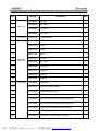
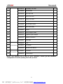
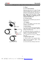
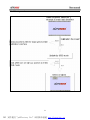
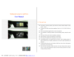
-Pro
(Engine Analyzer part)
User manual
Version 1.0
Copyright ©2006 by
Tech. Inc.
PDF 文件使用 "pdfFactory Pro" 试用版本创建 www.fineprint.cn
Disclaimer
All rights reserved, no part of this publication may be reproduced, stored in a retrieval system, or
transmitted in any form or by any methods, electronic, photocopying, recording, or otherwise, without
prior written permission of AUTOBOSS. Neither AUTOBOSS, nor its affiliates shall be liable to the
buyer of this product or third parties as a result of accident, misuse, alteration, or abuse of this product,
or failure to follow the written instructions from the manual.
Since different vehicles and their systems may behave differently under different operating conditions
and environment, AUTOBOSS cannot guarantee its product will work correctly with every system in
every vehicle. By using AUTOBOSS products, you are aware of the fact that its software and
hardware may contain errors or bugs, and thus provided “AS IS”. We will make our best effort to
correct errors and any bugs in our software, and hardware, but we specifically disclaim any liability for
damage to your computer or to your vehicle, and we do not promise to have any particular
improvements or software updates on any specific date.
Star-Pro is designed for sole purpose of diagnosing and repairing automotive electronic systems. Only
trained service personnel can operate it. Neither AUTOBOSS, nor its affiliates shall be liable to the
buyer of this product or third parties as a result of accident, misuse, alteration, or abuse of this product,
or failure to follow the written instructions from the manual. Every attempt has been made to provide
complete and accurate technical information based on factory service information available at the time
of publication. However, the right is reserved to make changes at any time without notice.
For any question, please contact AUTOBOSS by following ways:
(1) Visit AUTOBOSS website at http://www.autoboss.net;
(2) Send mail to AUTOBOSS Tech Inc customer service center at the following mail address: 5/F,
East Bldg. 304, Shangbu Industrial Park, Zhenxing Road, Futian,
Shenzhen 518028, China
(3) Send email to [email protected].
(4) Call AUTOBOSS office at 86-755-8328 5146, 86-755-8328 5370 or call your local distributors.
Trademark
The trademarks, logos, and service marks (“Marks”) displayed in this document are the property of
AUTOBOSS or other third parties. Users are not permitted to use these Marks without prior written
consent of AUTOBOSS or such third party which may own the Mark. AUTOBOSS is a registered
trademark of AUTOBOSS TECH. INC.
Copyright ©2006 by
- ii -
PDF 文件使用 "pdfFactory Pro" 试用版本创建 ÿwww.fineprint.cn
User Manual instruction:
Ø
This equipment must only be used by trained professionals.
Ø
Before using Star-Pro,please read this manual thoroughly。
Ø
The current user manual is based on the current features and functions available.
Any added features and functions of Star-Pro will be added to the user manual in
the future. Any updated version of user manual will be available at AUTOBOSS
website (http://www.autoboss.net)。
Ø
When reading the manual, please pay special attention to the words “Note”
“Caution” or “Warning”,read it carefully to ensure the safety。
Operation precautions
1. Product operation safety
Ø
When getting power from vehicle’s battery, make sure to attach the red clamp of
the battery cable to the positive side of the battery while black clamp to the
negative side of the battery;
Ø
Make sure you have connected the ground lead before test;
Ø
Use the dilapidated test lead may damage the unit;
Ø
When testing the vehicle, do ensure the ventilation is sufficient to prevent
inhalation of exhaust gas;
Ø
During testing, do ensure all the test leads and cables are correct connected and
not in direct contact with any hot objects;
Ø
A large majority of the vehicles is equipped with a high-voltage ignition system,
especially on electronic ignition and Coil-On-Plug ignition system. This
high-voltage ignition system will stop human’s heart from beating. Therefore,extra
caution is required when testing these systems。When the engine is running, test
operator is prohibited from touching any secondary coil or high-voltage wires。
2. Star-Pro main unit maintains
Ø
Avoid shaking the main unit as it may damage the internal components;
Ø
During testing,avoid unplugging the power cable;
Ø
Do not use hard or sharp objects to click the touch screen LCD; do not punch on
- iii -
PDF 文件使用 "pdfFactory Pro" 试用版本创建 www.fineprint.cn
the touch screen display; Do not let the touch screen exposed to the sunlight for a
long time;
Ø
If not used for a long time, please turn off the power. This can extend the life of the
main unit;
Ø
Caution: Stay from water or moisture;
Ø
Perform calibration every time before testing to keep the accuracy of the LCD;
Ø
Do not pull out or insert the main communication cable when the main unit is
working;
Ø
Keep the main unit away from strong magnetic field during the testing in order to
avoid the interference。
3. CF card maintains
Ø
Plug the CF card when the main unit is working may damage the CF card
permanently.
Ø
Keep the CF card away from magnetic field;
Ø
Do not plug or insert CF card too frequently;
Ø
When inserting the CF card into the main unit, make sure you get the right
direction. Normally the side with the label is facing up;
Ø
In case CF card is damaged and the program in the card cannot be used, please
use the following procedures to remake the CF card:
(1) Login AUTOBOSS website www.autoboss.net and download the necessary
programs to your personal computer.
(2) Format the CF card to FAT32.
(3) Write the programs onto the CF card.
NOTE: When CF card is damaged or cannot be read,format CF card to FAT32
format first and then continue installing the diagnostic programs。
- iv -
PDF 文件使用 "pdfFactory Pro" 试用版本创建 www.fineprint.cn
Table of Contents
Disclaimer ............................................................ ii
User Manual instruction:.............................................. iii
Operation precautions ................................................ iii
Chapter 1
Introduction to Star-Pro .................................... 1
1.1
Introduction....................................................................................................1
1.2 Star-Pro Main Unit Configuration .......................................................................1
1.3 Technical parameter ...........................................................................................2
1.4 Star-Pro Profile ...................................................................................................3
1.4.1 Main unit structure ...................................................................................3
1.4.2 Layout ......................................................................................................3
1.5
Star-Pro Unit Packing list...............................................................................4
1.6 Introduction of converter ....................................................................................6
Chapter 2
Operation Instruction ....................................... 8
2.1 Start ....................................................................................................................8
2.1.1 CF card installation ..................................................................................8
2.1.2 Power Supply...........................................................................................8
2.1.3 Start procedure.........................................................................................9
2.1.4 Main menu introduction..........................................................................10
2.2 Settings.............................................................................................................11
2.2.1 User Information ....................................................................................11
2.2.2 Language ...............................................................................................11
2.2.3 Display ...................................................................................................12
2.2.4 Calibration ..............................................................................................12
2.2.5 Projection ...............................................................................................12
2.3 Introduction of Engine Analyzer .......................................................................16
Chapter 3
Secondary Ignition ......................................... 18
3.1 Introduction.......................................................................................................18
3.2 Testing procedures ...........................................................................................18
3.2.1 Zero Calibration .....................................................................................18
3.2.2 Test leads connections...........................................................................18
3.2.3 Vehicle Manufacturer .............................................................................21
3.2.4 Connecting the leads .............................................................................24
-a -
PDF 文件使用 "pdfFactory Pro" 试用版本创建 åwww.fineprint.cn
Chapter 4
Primary Ignition ........................................... 27
4.1 Introduction.......................................................................................................27
4.2 Testing procedures ...........................................................................................27
4.2.1 Zero calibration ......................................................................................27
4.2.2 Test leads connection ............................................................................27
4.2.3 Vehicle Configuration .............................................................................29
Chapter 5
General Oscilloscope (DSO) ................................. 32
5.2 Testing procedures ...........................................................................................32
5.2.1 Zero calibration ......................................................................................32
5.2.2 Test lead connections ............................................................................32
5.2.3 Channel controls ....................................................................................33
Chapter 6
Automotive Oscilloscope(Auto DSO) .......................... 38
6.2 Testing procedures ........................................................................................38
6.2.1 Zero calibration ......................................................................................38
6.2.2 Test lead connections ............................................................................38
6.2.3 Choose component of testing ................................................................39
Chapter 7
Engine Analyzer............................................ 43
7.2 Testing procedures ........................................................................................43
7.2.1 Zero calibration ......................................................................................43
7.2.2 Test lead connections ............................................................................43
7.2.3 Adjustment and setting...........................................................................44
Chapter 8
Digital Multimeter ......................................... 46
8.1 Introduction.......................................................................................................46
8.2 Testing Procedures...........................................................................................46
8.2.1 Zero Calibration .....................................................................................46
8.2.2 Cable Connection ..................................................................................46
8.2.3 Choose component of testing ................................................................47
Chapter 9
User Setting............................................... 48
9.1 Language Setting .............................................................................................48
9.2 Date and Time ..................................................................................................48
9.3 Calibration ........................................................................................................49
9.3.1 Zero calibration ......................................................................................49
9.3.2 Gain calibration ......................................................................................49
9.3.3 Save as default ......................................................................................49
-b -
PDF 文件使用 "pdfFactory Pro" 试用版本创建 åwww.fineprint.cn
9.3.4 Use default .............................................................................................50
9.4 Basic Information..............................................................................................50
9.5 User Information...............................................................................................50
9.6 Memory Management ......................................................................................51
Chapter 10
Software Update .......................................... 52
10.1 Note ................................................................................................................52
10.2 Update steps ..................................................................................................52
10.2.1 Preparation...........................................................................................52
10.2.2 Update program downloading instruction ............................................53
10.2.3 Diagnostic program update..................................................................53
10.2.4 OS update ............................................................................................53
10.2.5 BIOS Update ........................................................................................54
Chapter 11
Troubleshooting .......................................... 55
11.1 FAQ during testing..........................................................................................55
11.2 Operation question. ........................................................................................55
Appendix 1 Secondary ignition patterns(Power and waster) .............. 57
Appendix 2 General Scope Waveform ...................................... 58
-c -
PDF 文件使用 "pdfFactory Pro" 试用版本创建 åwww.fineprint.cn
Chapter 1
Introduction to Star-Pro
1.1 Introduction
Welcome to use AUTOBOSS powerful
product Star-Pro.
Designed for professional automotive
technicians, Star-Pro utilizes a real-time
operating system with a number of
diagnostic instruments supported to
solve the sophisticated electrical and
mechanical systems on today’s modern
vehicles, such as testing vehicle sensors,
ECU input/output, ignition and analyzing
vehicle signals etc.
Features of Star-Pro:
l
Four groups signal collected
simultaneously for convenient
comparison
l
Select ignition types directly during
the testing
l
Compare the voltage between
power spark and waste spark for
DIS system
l
Can test integrated distributor
ignition system
l
Self learn of standard waveform
function supported, providing
convenient diagnosis
l
Common values preset function
supported for quick testing
l
Save, printout and replay the testing
results in static and dynamic mode
l
Colorful LCD display for visual
operation
1.2 Star-Pro Main Unit Configuration
Features
Parameter
CPU
ARM 7
Dimension
347MM(L)×181MM(W)×41MM(H)
1
PDF 文件使用 "pdfFactory Pro" 试用版本创建 www.fineprint.cn
Operating Mode
LCD Touch Screen
LCD
High Resolution 6.4” / 640*480 CCFL Backlight
Memory
FLASH 2MB,RAM 8MB
CF card
256 M
Glitch capture
400 ns
Bandwidth
500 KHz
Power supply
AC/DC,cigarette lighter/battery
Communication
USB(12Mbps) / Internet Interface(10Mbps)
4 independent A/Ds oscilloscope channel
Measuring channels
1 primary ignition channel / 2 secondary ignition channel
1 sync signal input channel
A/D converter
12 digitals
Memory depth
1M
Glitch capture
6M
EEPROM
EEPROM 8M
Sync dynamic memory
SDRAM 8M
1.3 Technical parameter
DC Voltage:9-16V (2A)
AC Voltage:220V 50Hz
Ambient:
5oC - 40oC
Humidity:
Lower than 85%
Storage:
-20℃~60℃
-20℃ less than 48h
60℃ less than 168h
2
PDF 文件使用 "pdfFactory Pro" 试用版本创建 www.fineprint.cn
1.4 Star-Pro Profile
1.4.1 Main unit structure
The structure of the main unit as shown
in left picture.
① Printer
② Main unit
③ Rubber handle
1.4.2 Layout
3
PDF 文件使用 "pdfFactory Pro" 试用版本创建 www.fineprint.cn
1.5 Star-Pro Unit packing list
Item
Number
1
30AB010A
Star-Pro
1
30AB003A
Mini printer
1
3
12AA008A
Touch Pen
1
4
30AB009A
Converter
1
30AD011A
CF Memory card
1
6
30AC134A
Nissan-14
1
7
30AC133A
Audi-4
1
8
30AC132A
Benz-4
1
9
30AC104A
OBD-16
1
30AC130A
Honda-3
1
30AC129A
MIT-12+16
1
12
30AC128A
Toyota-22
1
13
30AC127A
Toyota-17
1
14
30AC113A
BMW-20
1
15
30AC125A
Benz-38
1
31AC035A
Sync Probe
1
23
31AC032A
Black Big Alligator Clamp
2
24
31AC031A
Red Big Alligator Clamp
2
25
31AC027A
Blue Probe with Alligator and Piercing Clip
1
26
31AC026A
Green Probe with Alligator and Piercing Clip
1
27
31AC025A
Yellow Probe with Alligator and Piercing Clip
1
28
31AC024A
Red Probe with Alligator and Piercing Clip
1
29
31AC023A
Secondary Test Group Lead II (Black)
1
30
31AC022A
Secondary Test Group Lead II (Read)
1
2
Description
Qty
Main Unit
5
10
11
22
CF Card
Diagnostic
connector
Test leads
4
PDF 文件使用 "pdfFactory Pro" 试用版本创建 www.fineprint.cn
31
31AC021A
Secondary Test Lead
1
32
31AC020A
Ground Lead
1
33
31AC019A
Blue Test Lead
1
34
31AC018A
Green Test Lead
1
35
31AC017A
Yellow Test Lead
1
36
31AC016A
Red Test Lead
1
37
31AC036A
Star-Pro Main Cable
1
38
30AE041A
Main Cable (Star)
1
39
30AE023A
Jumper
1
40
30AE017A
Battery Adaptor Cable
1
41
30AE015A
Cigarette Lighter Adaptor
1
42
30AE013A
Network connection
1
43
30AE005A
USB cable
1
44
10AM002A
Fuse
2
10AV001A
DC Adaptor
1
15AA014A
Star-Pro User Manual
1
15AA003A
Certificate
1
10AW001A
Printing Paper
1
45
Accessories
46
47
Documents
48
Note:This Packing list is only for your reference. Please get the Standard
configuration from the packing list in the product.
5
PDF 文件使用 "pdfFactory Pro" 试用版本创建 www.fineprint.cn
1.6 Introduction of converter
The signal is adjusted and sent to the
main unit by the converter. Please see
the left picture. It is a standard converter.
1. A(CH1)
Port CH1 is the default trigger channel
for 4-Channel Oscilloscope, comparing
the relevant waveform. CH1 can also be
used for Digital Multimeter (DMM).
2. B、C、D(CH2、CH3、CH4)
Used for 4-Channel Oscilloscope testing.
Analyze and compare the waveform by
selecting relative channel from CH2 to
CH4.
The function of General Oscilloscope
(DSO), Special Oscilloscope (Auto DSO),
Digital Multimeter will be supported if
Port A, B, C, D are connected with the
red, yellow, blue and green test lead by
order.
3. E(COM)
Used for connecting the converter and
main cable. And transfer the adjusted
signal to communication module.
4. F(SEC IGN(-))
Port F is used for the secondary ignition
testing, connecting to black probe.
5. G(SEC IGN (+) )
Port G is used for secondary ignition
testing, connecting to the red probe.
Note: Port F and G are connected to
the red/black probe respectively for DI
and EI.
6. H(SYNC)
Port H is connected to SYNC probe. Its
function is identify ignition trigger signal
and used as Multimeter to test RPM.
Also, it will synchronize the signal during
the primary ignition and secondary
ignition, DSO, Auto DSO test.
6
PDF 文件使用 "pdfFactory Pro" 试用版本创建 www.fineprint.cn
7. I(PRI IGN)
Port I is connected to the primary pickup
connector leads for primary ignition test.
This function also can display the signal
output on the primary test interface.
8. J(
)
Connected to ground and provides signal
reference interface for
4-channel
oscilloscope. Also, it provides positive
reference interface for DMM test.
Note: J port connected to ground cable of
oscilloscope and the other side of the
accessory connected to vehicle ground
or
negative pole of vehicle battery is
used for providing the waveform and
current reference interface during test.
9. K(CURRENT-)
Connected to the negative pole of the
current clamp and is used for current
measurement.
10. L(CURRENT+)
Connected to the positive pole of the
current clamp and is used for current
measurement.
Note: K、L is connected to the small
current clamp or large current clamp for
amperage measurement.
7
PDF 文件使用 "pdfFactory Pro" 试用版本创建 www.fineprint.cn
Chapter 2
Operation Instruction
2.1 Start
2.1.1 CF card installation
While the main unit is off,insert CF card
(with the labeled size on the top) into CF
card slot on the main unit. Then turn on
the main unit by press the power button.
Note: Make sure the power is OFF
before changing or removing the CF
card from the main unit.
2.1.2 Power Supply
There are three methods to get power for
the main unit:
1. DC adaptor
Plug in the DC adaptor to the wall socket
to obtain a 12V DC power.
2. Vehicle Battery
DC adapter
(1) Connect A-side of the cigarette lighter
cable with A-side of the battery cable as
shown in the left picture.
(2) Clamp the red clip to positive (+)
terminal of the battery and black clip to
negative (-) terminal of the battery
(3) Connected the B side to Star-pro
main unit.
3. Cigarette lighter cable
(1) Insert A-side of the cigarette lighter
cable into the cigarette lighter cable
socket on the vehicle.
Cigarette lighter cable
(2) Connect B side to Star-pro main unit
8
PDF 文件使用 "pdfFactory Pro" 试用版本创建 Ùwww.fineprint.cn
2.1.3 Start procedure
9
PDF 文件使用 "pdfFactory Pro" 试用版本创建 www.fineprint.cn
2.1.4 Main menu introduction
Load paper
Print
180o rotation
Function
ECU simulation (demo) mode
Data record
Auto Scanner
Diagnostic scanner(Not available on A-2700)
Analyzer
Engine Analyzer
User information
Setup user information
Language
Change language between English and Chinese
Display
Adjust the contrast and color of the display
Touch Set
Adjust sensitivity of the touch screen display
Enter Projection
For education demo purchase. Can project the screen into PC
USB Update
Update software on CF program card
Self Check
Check and verify main unit hardware
Circuit
Display vehicle system circuit diagrams
Dictionary
English-Chinese dictionary
Keyboard
Numeric inputs
Shift
Chinese-English keypad
Diagnosis
Settings
Information
Keyboard
Main keys:
Help
Help information for operation
OK
Enter function
BACK
Back to previous interface
[↑][↓][←][→]
Page Up、Page Down、Left、
Right buttons
10
PDF 文件使用 "pdfFactory Pro" 试用版本创建 www.fineprint.cn
2.2 Settings
The [settings] menu includes:
l
User Information
l
Language
l
Display
l
Touch Set
l
Enter projection
l
USB update
l
System check
2.2.1 User Information
Click “User Information” under the
Settings menu and the screen will be
shown as in Figure. Type in the name,
phone number, fax and address and then
save it. This information will be shown in
the printout during paper printing.
The information can be input through the
keyboard by selecting the keyboard icon
under Keyboard menu. If incorrect
to
information is entered, just click
delete it. If you want to enter Chinese
characters, please press the button 中
first as shown. Press
information.
to save to
2.2.2 Language
Select
menu.
[Language]
under
[Settings]
NOTE: Star-pro has already set English
as the default language. Press
[language->中文] to switch into Chinese
11
PDF 文件使用 "pdfFactory Pro" 试用版本创建 www.fineprint.cn
2.2.3 Display
Select Settings from the main menu,
and then select Display; the Fig 2.7
page will pop out;
Adjust the optimum contrast with the
touch pen and choose black/white or
colour, the system will save the
adjustment and return to the main menu
automatically.
2.2.4 Calibration
There are two methods on making
calibration in order to keep accuracy of
the LCD screen.
Method 1:
Turn on the power and touch the LCD
screen for more than 2 seconds with the
touch pen to access the page shown on
the left:
Method 2:
Click the button “Touch set” under the
menu of Information.
The User must click the center of the
cross according to the information
displayed on the LCD screen to make
calibration. The machine will keep the
setting for next operation.
2.2.5 Demo
Demo is a projection function which is
very popular in Training school,
university or garage due to the
convenience---unnecessary connecting
to the car.
① Software download and installation
Please Login AUTOBOSS website
www.autoboss.net to download the
projection software.
12
PDF 文件使用 "pdfFactory Pro" 试用版本创建 www.fineprint.cn
Go to www.autoboss.net and select
[Download];
After entered download center, click the
icon of Star-Education Demo
to download the demo program to your
personal computer;
Double
click
educatedemo.exe
program.
the
and
13
PDF 文件使用 "pdfFactory Pro" 试用版本创建 www.fineprint.cn
icon
install
of
the
Click install to start the software
installation;
as
Click the icon
shown in left picture to enter education
projection mode.
After click the icon the left side interface
will on your personal computer;
② Connection Star-Pro to PC
Connect Network Cable to PC and
Star-Pro. One port is connected to the
Star-Pro and the other port is connected
to PC.
14
PDF 文件使用 "pdfFactory Pro" 试用版本创建 www.fineprint.cn
③ Demo
Follow the instruction bellow step by step
Click the button [enter projection] under
the menu of System Setting.
Click the button [save screen] on PC
monitor.
on the left corner of the
Click the icon
Star-Pro. The information of Star-Pro
will be displayed on the PC screen.
Note:
The screen displayed on PC will be a
little bit slower than Star-Pro. Click the
to fresh the PC display
button
each time.
④ Capture
Click the button save screen on
monitor to save the information.
information will be saved in
educatememo folder. The User
make lessons with these pictures.
15
PDF 文件使用 "pdfFactory Pro" 试用版本创建 www.fineprint.cn
PC
The
the
can
2.3 Introduction of Engine
Analyzer
In the main menu, select Analyzer under
Diagnostic menu and the following
screen will be shown as in Figure.
Star-Pro includes six different functions:
Primary ignition、 Secondary ignition、
Digital Storage Oscilloscope (DSO) 、
Auto Digital Oscilloscope (Auto DSO)、
Engine Analyzer 、 Digital Multi-meter
(DMM)。
The followings illustrates the features of
each functions:
1. Secondary ignition:
The following ignition systems can be
tested with Star-Pro:
Conventional ignition (external coil wire)
Conventional ignition(Internal coil wire)
Direct Ignition System(Distributor less)
Coil-Near-Plug Ignition (CNP)
Coil-On-Plug Ignition (COP)
2. Primary ignition:
The following ignition systems can be
tested with Star-Pro:
Distributor Ignition(External Coil)
Distributor Ignition(Internal Coil)
Coil-On-Plug Ignition(COP)
3. Digital Storage Oscilloscope (DSO)
The 4-channel oscilloscope allows you to
view multiple signals simultaneously.
16
PDF 文件使用 "pdfFactory Pro" 试用版本创建 www.fineprint.cn
The User can modify the parameters of
the oscilloscope and perform testing on
different vehicles.
4. Auto DSO
The 4-channel DSO allows users to view
multiple signals specific to automotive
applications simultaneously.
Special oscilloscope is used by someone
who is not familiar with the automotive
technology.
5. Engine analyzer
The main function of the engine analyzer
is to diagnose the starting, charging
systems of the vehicle, the sealing ability
of the cylinder, etc.
DMM
The DMM includes the following items:
DC voltage, AC voltage, DC current, DC
Low Current, DC High Current,
Frequency,
Duty
Cycle,
RPM,
Resistance, Pulse Width
Note: The functions of Star-Pro will be
explained in detail in the subsequent
chapters.
17
PDF 文件使用 "pdfFactory Pro" 试用版本创建 www.fineprint.cn
Chapter 3
Secondary Ignition
3.1 Introduction
1. Testable ignition types:
Distributor (with high-tension wire )、
Distributor(without high-tension wire)
、
Electronic (power and waste) 、
Coil-Near-Plug (CNP) and Coil-On-Plug
(COP) ignition systems;
2. Waveform Display Mode:
There are following display mode: Single
Cylinder, Parade, Raster, 3-Dimension,
Superimposed, Bar chart, etc. Different
display modes reflect:ignition voltage,
firing voltage (kV)、dwell time, burnt-time;
power/waste ratio, etc.
3.2 Testing procedures
The followings illustrates the testing
procedures of viewing secondary
ignition signals:
1.
Connecting the main unit to the
converter through the main test cable
2.
Supply 12V power through battery
cable
3.
Perform zero calibration.
4.
Connect the test leads.
5.
Select either Ignition Model Select
or Vehicle Manufacturer
6.
Adjustment and setting
7.
Save or print
3.2.1 Zero Calibration
Zero calibration is to verify the data
communication between the main unit
and the converter is good.
3.2.2 Test leads connections
Take a 4-cylinder engine with firing order
1-3-4-2 as an example, the test
procedure of Star-Pro is illustrated as
follows:
18
PDF 文件使用 "pdfFactory Pro" 试用版本创建 www.fineprint.cn
1. Distributor Ignition
(1) Connect the BNC side of the Sync
probe to the SYNC port. Mount the other
end of the sync probe to the coil wire of
cylinder #1.
(2) Connect the BNC side of the
secondary test lead to the SEC IGN+
port of the converter. Mount the other
side of the secondary probe to the high
tension coil wire of the ignition system;
(3) Connect the ground wire to the
port of the converter on one side and
mount the end to the negative side of the
battery or to the chassis ground.
Caution: Do not attach or remove the
leads from the coil wire when the
power of the main unit is ON!
(4) Ensure all cables and test leads are
clear from any rotating parts such as fan.
Then turn on the main unit and start the
engine to begin testing;
2. Direct ignition system
(1) Connect the BNC side of the SYNC
probe to the SYNC port of the converter.
Mount the other end of the SYNC probe
to the coil wire of cylinder #1. If the car
does not have distributor lead, take out
whatever cylinder’s ignition coil (take
cylinder #1 as example). Connect the
trigger cylinder and spark plug with a
connecting-cable and clamp one side of
the SYNC probe to the connecting-cable;
(2)Connect the BNC on Sec. Ignition
probe with SEC IGN (+) on the converter.
Another side of the Sec. Ignition probe
connects to the cylinder distributor lead
or connecting-cable with in testing;
Caution: Do not mount or remove the
test leads from the coil wire while the
power of the main unit is ON!
(3) Connect one side of the ground cable
on the converter box, another
to
side to negative pole of the battery or
ground cable on the vehicle.
Note: Make sure all cables or leads area
way from the rotating parts of the vehicle.
(4) Start the engine and begin testing.
19
PDF 文件使用 "pdfFactory Pro" 试用版本创建 www.fineprint.cn
3. Power/ waster ignition system
Ignition order: 1-3-4—2. The cylinder
to ignition coil positive: 1&2. The
cylinder to ignition coil negative: 3&4
(1) Connect one side of SYNC probe to
H port of converter, another side to
high-voltage lead of whatever cylinder.
(2) Connect one side of 4-chanel sec.
Ignition probe (Red) to SEC IGN (+) of
the converter, another side to the
cylinder distributor lead of cylinder #1
and cylinder #2 (that is positive side of
the Sec. Ignition output side);
(3) Connect one side of 4-chanel sec.
Ignition probe (Black) to SEC IGN (-) of
the converter, another side to the
cylinder distributor lead of cylinder #3and
cylinder #4 (that is negative side of the
Sec. Ignition output side);
Caution:Do not mount or remove the
test leads from the coil wire while the
power of the main unit is ON!
(4) connect one side of the ground cable
to
on the converter, another side to
the negative pole of battery or ground
cable of the vehicle;
(5) Make sure all cables or leads are
keep away from the rotating parts of the
vehicle;
(6) Start the engine and begin testing.
Caution: When using the SYNC
probe,the mounting direction is very
important. Typically the side with label
“AUTOBOSS” should be facing the
coil. Due to different makes and
models, the orientation may be varied.
If for some reason the proper signal
can be viewed,simply reverse the
orientation of the mounting。
20
PDF 文件使用 "pdfFactory Pro" 试用版本创建 www.fineprint.cn
3.2.3 Vehicle Manufacturer
On the main menu, select “Sec. Ignition”
button, the following three choices will
be available:
1. Ignition Mode Select
Click on “Ignition Mode Select”
Then Select the followings:
DI with coil wire
DI without coil wire
Coil-On-Plug (COP)
Coil-Near-Plug (CNP)
Power & waste firing
Then select No. of cylinders: 2, 3, 4, 5, 6,
8, 10, 12.
21
PDF 文件使用 "pdfFactory Pro" 试用版本创建 www.fineprint.cn
Then select the “firing order” to enter the
Sec. Ignition testing interface.
2. Vehicle Manufacturer
Select the region of manufacturer
Asia car includes vehicle makes from
Japan, Korea, and Southeast Asia。
Europe/ America cars include vehicle
makes from Europe and America.
China car includes all makes from
China。
Select Vehicle make.
Select No of cylinders: 2, 3, 4, 5, 6, 8, 10,
and 12.
22
PDF 文件使用 "pdfFactory Pro" 试用版本创建 www.fineprint.cn
Select “Motor type” by matching the 7th
digit of the VIN and then enter Secondary
ignition waveform pattern.
3. Last test record
Select the makes and models that have
been previously tested.
23
PDF 文件使用 "pdfFactory Pro" 试用版本创建 www.fineprint.cn
3.2.4 Connecting the leads
It is very important to mount the leads
correctly into the coils in order to view the
necessary waveform. This manual will
illustrate the ignition waveform of
4-cylinder, waste and power ignition
system with a firing order of 1-3-4-2,the
positive poles will be cylinder 1 and 2
while cylinder 3 and 4 will be negative
poles. The followings illustrates the setup
of the leads:
1. Triggering
Select“T. Cylinder”
Designate the coil wire mounted by Sync
Probe as the triggering cylinder (usually
cylinder 1).
2. Polarity
Select“Signal” to identify the polarity of
the signal in power and waste ignition
system.
In Power/ waster ignition system, the
negative pole of the ignition coil is
cylinder #3 and cylinder 4.
3. Trigger position settings
Select“Position”.
Users can adjust the trigger cylinder
position to adjust the waveform displayed
on the screen.
24
PDF 文件使用 "pdfFactory Pro" 试用版本创建 www.fineprint.cn
4. Prope
Select “prope”
Position is used to control the sensitivity
of the signal from the probe. Three
selections are currently available:
High (15%)
Medium (45%)
Low (75%)
5. Display mode selection
Select “Display Mode>”
Single
Cylinder,
Parade,
Raster,
3-Dimensional, Firing kV Bar chart,
Superimposed, Dwell and Probe. These
variety of waveform display illustrates:
firing kV and burnt time, etc.
6. Position setting
Select Posi from the men to adjust the X
and Y division levels. Use the up, down,
left or right arrow button to magnify,
shrink, enlarge or shorten the waveform。
7. Capture
Select “Capture”
Capture is used to record the snapshots
of the current waveforms。 Depending
on the playback time,user can select
either 10, 20, 30 or 40 pictures.
8. Lead help
Select “Lead help” for wiring diagram to
show how to set up.
25
PDF 文件使用 "pdfFactory Pro" 试用版本创建 www.fineprint.cn
9. Save and Print
Click “Freeze” and the following screen
should be shown as in Figure. Users can
print, save or replay the current
displayed waveform or pictures recorded
from Capture function. When finished,
select “RUN” to go back to the current
waveform display.
10. Exit
Select “EXIT” to go back to the main
menu.
26
PDF 文件使用 "pdfFactory Pro" 试用版本创建 www.fineprint.cn
Chapter 4
Primary Ignition
4.1 Introduction
1. Testable Primary Ignition Type:
Distributor type(External coil),
Distributor (External),
Coil-On-Plug(COP)ignition systems.
2. Waveform Display mode:
Single cylinder, parade, raster,
3-dimensional, firing kV, superimposed,
dwell and probe. These waveform
display modes illustrates the firing kV
and burnt time of the ignition system.
4.2 Testing procedures
The following illustrates the testing
procedures of testing primary ignition
system:
1. Connect the main unit to
converter through main cable;
the
2. Supply power to the main unit
through battery cable;
3. Perform zero calibration;
4. Connect the test leads;
5. Select vehicle make and model;
6. Adjustment and setting;
7. Save and print
4.2.1 Zero calibration
Zero calibration is to verify the data
communication between the main unit
and the converter is good.
4.2.2 Test leads connection
1. Distributor ignition
Connect the BNC side of the SYNC
probe to the SYNC port of the converter.
Mount the other end of the SYNC probe
to the coil wire of the cylinder #1;
Caution: Do not attach or remove the
test leads from the coil wire when the
power of the main unit is ON!
Connect the BNC side of the read probe
to the PRI IGN port of the converter.
27
PDF 文件使用 "pdfFactory Pro" 试用版本创建 www.fineprint.cn
Mount the alligator (piercing) clip of the
test lead to the negative pole of the
primary coil;
Connect the BNC side of the ground wire
to the
port of the converter on one
side and mount the clip side of the
ground wire to the negative pole of the
battery or chassis ground;
Ensure all cables and test leads are clear
from any rotating parts (like cooling fan);
Start the engine and begin testing.
2. Coil-On-Plug (COP) ignition
Remove the coil pack of the trigger
cylinder. Place a jumper spark plug wire
from the coil pack to the spark plug. Then
connect the Sync Probe to the jumper
spark plug wire that was installed.
Connect the primary ignition lead to the
converter and to the negative pole of the
primary coil.
Caution: Do not attach or remove the
test leads from the coil wire when the
power of the main unit is ON!
Connect the BNC side of the ground wire
port of the converter on one
to the
side and mount the clip side of the
ground wire to the negative pole of the
battery or chassis ground;
Ensure all cables and test leads are clear
from any rotating parts (like cooling fan);
Start the engine and begin testing.
Caution:
When mounting the SYNC probe to
the coil wire,make sure the side with
AUTOBOSS label is facing the coil.
Due to the different vehicle makes and
models, the orientation of the coil
configurations may be different. If for
some reasons the ignition waveform
cannot be viewed, simply reverse the
orientation of the SYNC probe.
28
PDF 文件使用 "pdfFactory Pro" 试用版本创建 www.fineprint.cn
4.2.3 Vehicle Configuration
The primary ignition pattern display can
be selected by the following three
categories:
1.
Select by ‘Ignition Mode’
Click “Ignition Mode Select” and press
‘Ok’ button,
Then Select the followings:
Distributor(External Coil)
Distributor(Internal Coil)
Coil-on-plug(COP)
Select number of cylinders: 2, 3, 4, 5, 6,
8, 10, 12.
29
PDF 文件使用 "pdfFactory Pro" 试用版本创建 www.fineprint.cn
Select “Firing order” and click OK to
enter Pri. Ignition testing interface.
2. Select by ‘Vehicle Manufacturer’
Select the region of manufacturer
Asia car includes vehicle makes from
Japan, Korea, and Southeast Asia.
Europe/ America cars include vehicle
makes from Europe and America.
China car includes all makes from
China.
Select Vehicle manufacturer
Select number of cylinders
The number of cylinders:2, 3, 4, 5, 6, 8,
10, 12.
30
PDF 文件使用 "pdfFactory Pro" 试用版本创建 www.fineprint.cn
Select the engine model
Click ‘ok’ to start test
3. Select by ‘Last test record’
Select one and press ’ok’ to start test
4.2.4 Adjustment and setting
Same as secondary ignition.
31
PDF 文件使用 "pdfFactory Pro" 试用版本创建 www.fineprint.cn
Chapter 5
General Oscilloscope (DSO)
5.1 Introduction
The 4-Channel Oscilloscope is an
easy-to-use and versatile tool that allows
access to any automotive
computer-controlled circuit.
5.2 Testing procedures
The testing procedure of the general
oscilloscope (DSO) is as follows:
Caution:Do not attach or remove any
test leads from the coil wire while the
power of the main unit is ON!
1. Connecting the main unit to the
converter through the main test cable
2. Supply 12V power through battery
cable.
3. Perform zero calibration.
4. Connect the test leads.
5. Channel controls
6. Save and print.
5.2.1 Zero calibration
Zero calibration is to verify the data
communication between the main unit
and the converter is good.
5.2.2 Test lead connections
Connect the test point to CHA, CHB,
CHC and CHD by the red, yellow, blue
and green cables. ( You can choice
connect how many and which channel by
necessary.)
port
Connect the ground wire to the
of the converter on one side and mount
the end to the negative side of the
battery or to the chassis ground. Ensure
all cables and test leads are clear from
any rotating parts such as fan. Then turn
32
PDF 文件使用 "pdfFactory Pro" 试用版本创建 www.fineprint.cn
on the main unit and start the engine to
begin testing;
5.2.3 Channel controls
The Oscilloscope has four separate
channels that can display data
simultaneously.
1. Channel setting
The channel buttons are located in
bottom left corner of the touch screen
display. Touching a channel button gives
you access to the settings specific to that
individual channel.
Click “Run” or “Stop” to turn the channel
on or off.
(1) Offset
Adjusting the offset changes the vertical
position of an individual signal on the
touch screen display.
(2) AC/DC coupling
Selecting the correct type of the coupling
mode for your signal is important for
accurate testing.
AC coupling: The mode displays only
the AC component of the signal under
examination.
DC coupling: The mode displays both
AC and DC components of the signal.
This is the default setting for four
channels.
Ground coupling: The mode ties the
internal A/D input to ground.
33
PDF 文件使用 "pdfFactory Pro" 试用版本创建 www.fineprint.cn
2. Trigger setup
The Star-Pro has a set of the trigger
controls that determine the exact instant
the trace begins the sweep across the
screen.
If a trigger is set at a specific voltage
level, and the signal being sampled
achieves that trigger level voltage, then
the Star-Pro displays the signal.
Trigger source
Trigger source allows you to choose from
a wide variety of sources-CH1, CH2,
CH3, CH4.
Trigger mode
There are four different trigger modes to
choose
from
when
viewing
a
signal-Normal, Auto, Single Shot and
Free Run.
Normal trigger: Normal trigger is a
common trigger mode and requires that
you know the characteristics of the signal
you are trying to display.
Auto trigger: Auto trigger is the easiest
mode of trigger to use when viewing an
automotive signal. The Star-Pro displays
a signal that meets the trigger level at the
trigger position. If the signal does not
meet the trigger level condition, Star-Pro
automatically displays any signal that is
received.
Single Shot trigger: Single shot trigger
is used when you want to capture a
certain characteristic of a know signal.
34
PDF 文件使用 "pdfFactory Pro" 试用版本创建 www.fineprint.cn
Free Run: Free run trigger type is, in fact,
a mode that eliminates the trigger
function.
Trigger level
Trigger level determines the height of the
signal that must be met for the Star-Pro
to trigger and display the acquired signal.
You can adjust the height of the trigger
level by using the [↑] and [↓] touch
screen buttons.
Trigger position
Trigger
position
determines
the
horizontal position where the trigger level
condition is met. The trigger position can
be move to any horizontal location on the
signal display area in increments of 5%
by [←] and [→] touch screen buttons.
Trigger edge
Trigger edge works in conjunction with
the trigger level. Any signal that meets
the trigger level condition and your
choice trigger edge (Rising and Falling)
is displayed at the trigger position. If
Rising Edge is selected, only a rising
signal that reaches the trigger level and
transitions to that voltage from a lower
voltage meets the trigger conditions and
displayed. A Falling Edge trigger works
just the opposite.
Auto set
If you don’t know the signal characteristic
of the component or if you don’t want to
manually make adjustments. Choose
Auto set.
35
PDF 文件使用 "pdfFactory Pro" 试用版本创建 www.fineprint.cn
3. Default setup
The “Default” button returns the settings
back to the factory default settings.
Grid
Display the grid or not.
Cursors
You can enable two horizontal and two
vertical cursors to make precise
measurements of waveforms display on
the grid. You can turn the cursors on and
off.
Horizontal cursor: You can press
“H.CSR” button to choose “H1”, “H2” and
“Cancel all cursor”. Then press “H1” or
“H2” to active cursors or press “Cancel
all cursor” button to cancel all cursors.
You can move the cursor by using [←]
and [→] buttons.
Vertical cursor: you can press “V.CSR”
button to choose “V1”, “V2” and “Cancel
all cursor”. Then press “V1” or “V2” to
active cursors or press “Cancel all
cursor” button to cancel all cursors. You
can move the cursor by using [↑] and [↓]
buttons.
36
PDF 文件使用 "pdfFactory Pro" 试用版本创建 www.fineprint.cn
4. Parameters
It can display the signal characteristics
that you are testing.
5. Save and print
Click “Freeze” and the following screen
should be shown as in Figure. Users can
print, save or replay the current
displayed waveform or pictures recorded
from Capture function. When finished,
select “RUN” to go back to the current
waveform display.
37
PDF 文件使用 "pdfFactory Pro" 试用版本创建 www.fineprint.cn
Chapter 6
Automotive Oscilloscope(Auto DSO)
6.1
Introduction
The Automotive Oscilloscope stores
some
signal
characteristics
of
automotive components. You needn’t to
set trigger level when testing. It is an
easy-to-use tool.
6.2
Testing procedures
The testing procedures of the
automotive oscilloscope is as follows:
1. Connecting the main unit to the
converter through the main test cable
2. Supply 12V power through battery
cable.
3. Perform zero calibration.
4. Connect the test leads.
5. Choose component of testing.
6. Save and print.
Caution: Do not attach or remove any
test leads from the coil wire when the
power of the main unit is ON!
6.2.1 Zero calibration
Zero calibration is to verify the data
communication between the main unit
and the converter is good.
6.2.2 Test lead connections
Connect the test point to ChA, ChB, ChC
and ChD by the red, yellow, blue and
green cables.(You can choice connect
how many and which channel by
necessary.)
port
Connect the ground wire to the
of the converter on one side and mount
the end to the negative side of the
battery or to the chassis ground.
38
PDF 文件使用 "pdfFactory Pro" 试用版本创建 www.fineprint.cn
6.2.3 Choose component of testing
Type
Testable item
Sensors
Oxygen sensor
MAP (Analog)
MAP (Digital)
TPS
EGR valve position (EVP)
Vehicle speed sensor (Analog)
Vehicle speed sensor (Digital)
ECT
MAF (Analog)
MAF (Digital) Low frequency
MAF (Digital) high frequency
Wheel speed (WSS)
Knock sensor
IAT
CKP sensor (Hall)
CKP sensor (Magnetic)
CMP sensor (Hall)
39
PDF 文件使用 "pdfFactory Pro" 试用版本创建 www.fineprint.cn
CMP sensor (Magnetic)
BARO (Analog)
BARO (Digital)
CAN BUS
EGR
Idle air control(IAC)
Idle speed control (ISC)
Air bypass(TAB)
Shift solenoid valve
Air diverter (TAD)
Actuators
Canister purge (CANP)
Increase to press
ABS solenoid valve
Mix with adjustment control
Hydraulic pneumatic control in gearbox valve
Gearbox lock computer valve
Negative control ( Common)
Fuel injectors
Peak’s hold
40
PDF 文件使用 "pdfFactory Pro" 试用版本创建 www.fineprint.cn
Type
Testable item
Primary
Secondary
Ignition system
Sync probe
Secondary/Sync
Primary/Sync
Hall effect P/U
Magnetic P/U
Distributor
Spark timing
Optical P/U
Charger
Battery voltage
Electrical
Ground
Alternator ripple
Fuel pump
Primary ignition
Current waveforms
Low current probe
High current probe
41
PDF 文件使用 "pdfFactory Pro" 试用版本创建 www.fineprint.cn
AC vacuum
DC vacuum
Vacuum
AC/DC vacuum/Sync
AC vacuum/Sync
Pressure
Pressure
Pressure/Sync
Other settings
Same as the settings
oscilloscope (DSO).
42
PDF 文件使用 "pdfFactory Pro" 试用版本创建 www.fineprint.cn
of
general
Chapter 7
Engine Analyzer
7.1 Introduction
Engine analyzer includes Charger test
and Starter test.
Charger test: It can test the charger by
the waveform of the voltage and current
when the charger working.
Starter test: It can test the starter by the
waveform of the voltage and current
when the starter working.
7.2
Testing procedures
1. Connecting the main unit to the
converter through the main test cable
2. Supply 12V power through battery
cable.
3.
Perform zero calibration.
4.
Connect the test leads.
5.
Adjustment and setting.
6.
Save and print.
7.2.1 Zero calibration
Zero calibration is to verify the data
communication between the main unit
and the converter is good. For an
operation of zero calibration, see 9.3.1.
7.2.2 Test lead connections
Charger test:
Caution: Do not attach or remove any
test leads from the coil wire when the
power of the main unit is ON!
Connect the current clamp to the charger
positive cable, and connect the other
side of current clamp to the CURRENT+
43
PDF 文件使用 "pdfFactory Pro" 试用版本创建 www.fineprint.cn
and CURRENT- port of the converter.
Connect the ground wire to the
port
of the converter on one side and mount
the end to the negative side of the
battery or to the chassis ground.
Ensure all cables and test leads are clear
from any rotating parts such as fan. Then
turn on the main unit and start the engine
to begin testing.
Starter test:
Caution: Do not attach or remove the
test leads from the connections when
the power of the main unit is ON!
Connect the current clamp to the starter
positive cable, and connect the other
side of current clamp to the CURRENT+
and CURRENT- port of the converter.
port
Connect the ground wire to the
of the converter on one side and mount
the end to the negative side of the
battery or to the chassis ground.
Ensure all cables and test leads are clear
from any rotating parts such as fan. Then
turn on the main unit and start the engine
to begin testing.
7.2.3 Adjustment and setting
Current clamp selection:
1mV/10mA
1mV/100mA
1mV/1000mA
Voltage / Current exchange
It can exchange between voltage mode
and current mode.
44
PDF 文件使用 "pdfFactory Pro" 试用版本创建 Àwww.fineprint.cn
Save and print
Click “Freeze” and the following screen
should be shown as in Figure. Users can
print, save or replay the current displayed
waveform or pictures recorded from
Capture function. When finished, select
“RUN” to go back to the current waveform
display.
45
PDF 文件使用 "pdfFactory Pro" 试用版本创建 www.fineprint.cn
Chapter 8
Digital Multimeter
8.1 Introduction
The Digital Multimeter (DMM) is a
powerful diagnostic tool that allows you
to determine specific values of different
measurement modes. The DMM modes
include DC and AC voltage, resistance,
continuity, and diode check. The DMM’s
large display makes it ideal for
measuring a variety of general signals as
well as automotive signals.
8.2 Testing Procedures
The testing procedures of the digital
multimeter is as following:
1. Connecting the main unit to the
converter through the main test cable
2. Supply 12V power through battery
cable.
3. Perform zero calibration.
4. Connect the test leads.
5. Choose component of testing.
6. Save and print.
8.2.1 Zero Calibration
For an operation of zero calibration, see
9.3.1.
8.2.2 Cable Connection
Cable Connection 1:
Connect the red test cable to the port
CH1 on the converter. Then connect the
other side of the red test cable to the test
point.
port
Connect the ground wire to the
of the converter on one side and mount
the end to the negative side of the
battery or to the chassis ground.
Note:Do not plug or insert main cable
when the scanner is powered
on!
Remark:Cable connection 1 only for
current, voltage, resistance, duty
cycle and frequency modes.
46
PDF 文件使用 "pdfFactory Pro" 试用版本创建 www.fineprint.cn
Cable Connection 2:
Connect the sync cable to the port CH1
on the converter. Then connect the sync
probe to the high-tension wire.
port
Connect the ground wire to the
of the converter on one side and mount
the end to the negative side of the
battery or to the chassis ground.
Remark:Cable connection 2 only for
RPM mode.
Note:Do not plug or insert main cable
when the scanner is powered
on!
8.2.3 Choose component of testing
The component include: DC, AC, Large
current, Small current, FREQ, RES,
Fluctuation, Air ratio, PRM, Temperature,
Pressure, Vacuum.
Lead help
Look for the lead reference by click it.
Keep
Keep the value display on the screen.
Refurbish
Refurbish the display of the screen.
47
PDF 文件使用 "pdfFactory Pro" 试用版本创建 www.fineprint.cn
Chapter 9
User Setting
Click the button [Setup] on the main
interface to enter the user setting
interface.
Users can setup language, date & time,
calibration, system information, user
information or file management on the
user setting interface.
9.1 Language Setting
The user can select Chinese or English
by click the different language button on
[Language Setting] interface.
9.2 Date and Time
Click the button [Date & Time] to enter
date and time setting interface. Please
input year/month/date hour/minute in
order by the keyboard. Click [Enter] to
save the settings.
48
PDF 文件使用 "pdfFactory Pro" 试用版本创建 ÿwww.fineprint.cn
9.3 Calibration
On calibration interface, the user can
calibrate the zero point and gain; also the
user can save the setting as default or
use the default settings.
9.3.1 Zero calibration
The sampling of AD range is from 0 to
4095, and the relevant voltage range is
from +1V to -1V. So, generally the zero
point is 2048. Once the zero point
excursions from the 2048, the user
should adjust it by zero calibration.
Operation steps:
① Connect the analyzer with converter
and disconnect all of the test leads.
Enter [zero calibration] interface.
② Input the 6 bit codes “888888” to
enter the calibration. Click the button
[ok] for several times as per the hint
above [ok] button. During the
calibration, please observe if the
values are beside 2048. Normally,
the values are 2048±200 or larger.
③ After finished all the procedures, click
the button [Exit] to return to
calibration interface.
9.3.2 Gain calibration
The system need gain calibration after
complete the zero calibration. Normally
the AD value is 1.000. Please calibrate
the gain value via this function to ensure
the accurate.
Note: AUTOBOSS had done the gain
calibration before package. So once
the value is not accurate, please
contact AUTOBOSS service center or
our distributor for help. The users can
not calibrate by themselves.
9.3.3 Save as default
Save the accurate calibrated values as
default.
49
PDF 文件使用 "pdfFactory Pro" 试用版本创建 www.fineprint.cn
9.3.4 Use default
Use the last accurate calibrated values
as default.
9.4 Basic Information
The User can check basic information of
the diagnostic scanner, such as the
hardware version, software version, S/N
number after click the “Enter”. See the
picture shown on the left.
9.5 User Information
The User can change or browse the User
Information.
Browse User Information
50
PDF 文件使用 "pdfFactory Pro" 试用版本创建 www.fineprint.cn
Change User Information:
Select the items to be changed with the
touch pen and input the amendments
through the built-in keyboard. The items
include name, phone, fax and address.
Click “space” between two words.
Click “
” to delete the letters.
Click “Enter” to save the amendment.
9.6 Memory Management
There are three modes for memory
inquiry:
1. Inquiry by testing unit
Including : primary ignition, secondary
ignition, general scope, Automotive
oscilloscope, Engine analyzer, digital
multimeter and Exhaust fume analyzer.
2. Inquiry by waveform
Including:standard waveform and
malfunction waveform
3. Inquiry by Car User
51
PDF 文件使用 "pdfFactory Pro" 试用版本创建 www.fineprint.cn
Chapter 10 Software Update
10.1 Note
Please read the following instructions
before operating the update:
(1) Make sure the CF card is in the CF
card socket of Star-Pro main unit.
1、12V Adaptor
(2) Make sure the power is stable and all
cables are well connected when you are
ready to upgrade the software. We
suggest to use UPS to protect the CF
card during upgrading because the CF
card may damaged if the power cut-off or
the cable disconnected.
2、Power port
3、USB port for Main unit
(3) Please do not do any other operation
on computer or Star-pro during the CF
card upgrading.
4、USB Port for PC
5、PC
10.2 Update steps
10.2.1 Preparation
(1) Personal computer with windows
2000 or windows XP operation system.
And the computer must connect to
internet. If your computer is Windows 98,
you should download and setup USB
driver too;
(2) Connecting Star-pro main unit and
personal computer with the USB cable in
the package;
(3) Connect the Star-pro main unit and
power with the 12V adaptor. Make sure
all cables are correctly connected. See
the left picture;
(4) Power on Star-pro main unit. Click the
USB icon on right up position of the main
unit or select [USB mode] under [System
settings] on the main interface to enter
USB update mode. See the left picture.
Note: If your personal computer
connected more than one moveable disk,
please enter [my computer] and make
sure you find the right one which belongs
to Star-pro. So this can ensure the
update success and also protect the data
on other moveable disks.
52
PDF 文件使用 "pdfFactory Pro" 试用版本创建 www.fineprint.cn
10.2.2 Update program downloading
instruction
Login
in
AUTOBOSS
http://www.autoboss.net。
Select “English
download center
version”
website:
and
enter
Select “download” on the main interface
of AUOTOBOSS website and enter
“Star-pro” download section to download
the program or operation system and
save them to your personal computer.
10.2.3 Diagnostic program update
1. Download the relative programs in
Chinese car, European car or Asia car
section to your personal computer. Save
them on the desktop.
2. Connect Star-pro with PC as per the
connecting method we introduced in
section 10.2.1 and enter USB update
mode.
3. Executing the update programs which
you just download form AUTOBOSS
website and saved on the desktop. Click
the installation by the hints on the screen
until you finished the whole operation.
See the left diagram.
4. Safely remove the USB device and
disconnect the USB cable, restart the
unit to finish the upgrading.
Note: Make sure you removed the USB
device. If you forgot this step may lead
the update failed and you should redo
every step.
10.2.4 OS update
1. Download the operation system
update programs to the desktop of your
personal computer.
2. Connect Star-pro with PC as per the
connecting method we introduced in
section 10.2.1 and enter USB update
mode.
3. Executing the update programs which
you just download form AUTOBOSS
53
PDF 文件使用 "pdfFactory Pro" 试用版本创建 www.fineprint.cn
website and saved on the desktop. Click
the installation by the hints on the screen
until you finished the whole operation.
See the left diagram.
4. Safely remove the USB device and
disconnect the USB cable, restart the
unit to finish the upgrading.
Note: Make sure you removed the USB
device. If you forgot this step may lead
the update failed and you should redo
every step.
10.2.5 BIOS Update
1. Download BIOS update program from
AUTOBOSS website to the desktop of
your personal computer.
2. Restart the main unit and click the box
in the middle by the hints on the main
unit with touch pen. The System can
update the BIOS automatically.
3. After the BIOS upgrading you must
upgrade the OS as per the instruction in
section 10.2.4, or the unit can not work.
Note: (1) Before you upgrading the
BIOS, please check is the BIOS
version of the Star-pro is lower than
the one on AUTOBOSS website. Or
you need not to upgrade it.
(2) We suggest to use UPS to protect
the stable voltage during upgrading
the BIOS, because the power cut-off
during upgrading the BOIS will
damage the main unit.
54
PDF 文件使用 "pdfFactory Pro" 试用版本创建 www.fineprint.cn
Chapter 11 Troubleshooting
11.1 FAQ during testing
1. Why the main unit, CF card and converter can not change with user’s mind?
Answer: Because every set of main unit, CF card and converter box is unique. Only the
ones in the same set can do A/D convert correctly. Or the fault by A/D convert will lead
the signal inaccurate.
2. why the SYNC signal do not stable during pri. ignition ?
Answer: Normally we use the cylinder #1 as trigger cylinder during pri. Ignition testing.
So one side of the SYNC probe is clamed on the cylinder distributor cable of cylinder
#1. If cylinder #1 did not work very well can infect the whole test There are three
method to resolve this problem.
① change another trigger cylinder;
② change the clamp direction of the CYNC probe;
③ Redo the zero calibration.
3. Why the waveform do not stable or no wave form during Pri. or Sec. Ignition
testing?
Answer: During the ignition testing please pay attention to the following items.
① Select correct ignition order;
② change the current direction of the cylinder;
③ Make sure the Sec. ignition probes which are free do not short to
ground.(4-channel style)
4. Why we must do the zero calibration before test?
Answer: The sample AD got is range from 0 to 4095, and its voltage is range from +1V
to -1V, so normally the zero point is 2048. In the actual operation the zero point will
departure from 2048, this problem can be solved by zero calibration. Zero calibration
ensures the test accurate.
5. The waveform does not stable during the DSO/Auto DSO test. What can we
do?
Answer: Users can click “trigger” to set the Trigger posi, Trigger mode, Trigger edge,
Trigger source setup.
6. We remove the main cable when the unit is on, then turn on the unit but the
unit no response.
Answer: Possible reason: battery clamps burned. Please change the battery clamp.
The users must pay attention that the main cable can not be removed when the unit is
on.
11.2 Operation question.
1. The screen has a cross the stays when turned on the unit.
Answer: one possible reason is you have entered the screen calibration mode. Please
55
PDF 文件使用 "pdfFactory Pro" 试用版本创建 www.fineprint.cn
click the cross center as per the hints on the screen. After the calibration you can get
the main interface. The other possible reason is the screen is blocked. Please contact
AUTOBOSS customer service center to solve.
2. The screen displayed CF card read failed when the unit turned on.
Answer: Possible reason:
① The CF card is not in the Star-Pro. Turn off the unit and insert the CF card;
② CF loose. Turn off the unit and unplug the CF card then insert the CF card. After all
the steps then turn on the unit;
③ CF card damaged, Please change the CF card;
④ CF card format incorrect. Please reformat the CF card.
3. The screen can not display in order.
Answer: Restart the unit. This indicate there is any BUG in the program, Please contact
AUTOBOSS customer service center or download the latest DSC program from
AUTOBOSS website and update the unit.
4. The form or data can not be saved.
Answer: If the wave form can not be saved, maybe the CF card is full. Please delete
some old form or change a large size CF card.
5. The response is incorrect when the touch pen clicks the screen.
Answer: Do the screen calibration. Click the [settings] and select screen calibration
then do the operation by the hints on the screen.
6. No response when click the screen.
Answer: contact AUTOBOSS customer service center or your local distributor or
download the latest DSC program from AUTOBOSS website.
7. The screen display is not clear.
Answer: Adjust the screen display or color in [settings] menu.
8. The screen color is not the same on the same unit.
Answer: The screen may have fault, please contact AUTOBOSS customer service
center or your local distributor.
56
PDF 文件使用 "pdfFactory Pro" 试用版本创建 www.fineprint.cn
Appendix 1 Secondary ignition patterns(Power and waster)
Single cylinder display
Super imposed
Bar chart —— firing kV
Parade
Raster
Power-to-waste ratio
57
PDF 文件使用 "pdfFactory Pro" 试用版本创建 www.fineprint.cn
Appendix 2 General Scope Waveform
IGF
EVAP
Mass Air Fluid( MAF )
CAN
TPS
Injector Signal Waveform
58
PDF 文件使用 "pdfFactory Pro" 试用版本创建 www.fineprint.cn