1
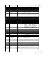
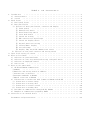
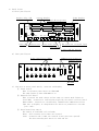
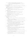
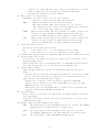
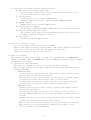
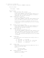
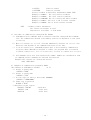
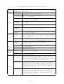
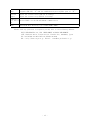
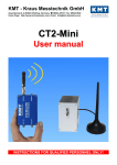
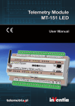
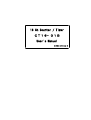
16 Ch Counter / Timer
CT16−01B
User's Manual
(1738A revision 4)
Mode
R/L
R
R
R
R
R
R/L
R/L
R/L
R
R/L
R/L
R/L
R
R
R
R/L
R/L
L
R
R
R/L
R
R/L
R
R
R
R
R/L
R
R
R
R
R
R/L
R/L
CT16-01B Command Table ( for RS232C,GP-IB)
Contents of Command
Command
Remarks
Read Alarm Status
ARM?
Query on overflow status
Clear All
CLAL
Clear all counters and a timer
Clear Preset Counter CLPC
Clear the ch 15 counter
Clear Timer
CLTM
Clear the timer
Clear Counter xx
CLCTxx
counter xx:00-15 clear "CLCT05"
Clear Counter xx-yy
CLCTxxyy
counter xx - yy clear "CLCT0514"
Read Preset Value of CPR?
Response is decimal or hexadecimal
Counter
8 digits(Kcts Unit)
Read Counter xx
CTR?xx
counter xx : Read 00-15
Response is decimal or hexadecimal
12 (significant 10) digits
Disable Alarm
DSAL
SRQ interrupt when stopped
Disable Auto Stop
DSAS
Counter/Timer stop disable
Echo OFF
ECHF
For RS232C
Echo ON
ECHN
For RS232C
Enable Alarm
ENAL
SRQ interrupt when stopped
Enable Counter Stop
ENCS
Count stop by the preset count value
Enable Timer Stop
ENTS
Count stop by the preset time value
Local
LOCL
Change to local mode
Read Mode
MOD?
Query on mode, response is e.g.R_SN_T_F
R:REMOTE
L:LOCAL
SN:SINGLE,
RP:REPEAT ST:STORAGE T:TIMER STOP
C:COUNTER STOP
N:NOT STOP
O:COUNTER ON
F:COUNTER OFF
Read Radix
RDX?
Is send data binary or decimal?
Response is e.g. BN
Remote
REMT
Change to remote mode
Repeat Mode
REPT
Change to repeat mode
Reset
REST
Reset the unit
Set Binary
SBIN
Send data is in hexadecimal
Set Preset Value of
SCPR・・・・・・・
Setting of the preset counter
Counter
e.g. SCPRddddddd
d:decimal 7 digits
Set Decimal
SDEC
Send data is in decimal
Set Display1
SDP1
Display 0-7 ch
Set Display2
SDP2
Display 8-15ch
Set Interval
SINT・・
Set an interval in repeat mode by 0.1
second
e.g. SINTdd dd:01-99
Single Mode
SNGL
Change to single mode
Read Prest Value of
TPR?
Response is decimal or hexadecimal
Timer
8 digits (mS Unit)
Emergency Stop
STEM
Count stop (immediately stop)
Stop
STOP
Count stop (stop after a cycle)
Storage Mode
STOR
Change to storage mode
Set Preset Value of
STPR・・・・・・・
e.g. STPRddddddd
Timer
d: decimal 7 digit (mS unit)
Start
STRT
Start count
Read Timer
TMR?
Response is decimal or hexadecimal
12 (significant 10) digits (μS unit)
Read Version
VER?
Response is e.g. 1.2 03-12-22
Table
of
Contents
1.Introduction
・・・・・・・・・・・・・・・・・・・・・・・・・・・・・・・・・・・・1
1) characteristics ・・・・・・・・・・・・・・・・・・・・・・・・・・・・・・・・・1
2) control ・・・・・・・・・・・・・・・・・・・・・・・・・・・・・・・・・・・・・2
2.Panel layout
・・・・・・・・・・・・・・・・・・・・・・・・・・・・・・・・・・・・3
1) Front panel layout
・・・・・・・・・・・・・・・・・・・・・・・・・・・・・・・3
2) Rear panel layout ・・・・・・・・・・・・・・・・・・・・・・・・・・・・・・・・3
3) Function of front panel switch, connector and display ・・・・・・・・・・・・・3
① Power switch
・・・・・・・・・・・・・・・・・・・・・・・・・・・・・・・3
② Remote/Local switch ・・・・・・・・・・・・・・・・・・・・・・・・・・・・3
③ Reset/Start/Stop switch ・・・・・・・・・・・・・・・・・・・・・・・・・・3
④ Count mode switch ・・・・・・・・・・・・・・・・・・・・・・・・・・・・・4
⑤ Switch for setting
・・・・・・・・・・・・・・・・・・・・・・・・・・・・4
⑥ BNC connector for signal input
・・・・・・・・・・・・・・・・・・・・・・5
⑦ Switch for display switch ・・・・・・・・・・・・・・・・・・・・・・・・・5
⑧ Digital switch for setting
・・・・・・・・・・・・・・・・・・・・・・・・5
⑨ Counter/Timer display
・・・・・・・・・・・・・・・・・・・・・・・・・・5
⑩ Over flow ramp
・・・・・・・・・・・・・・・・・・・・・・・・・・・・・・5
⑪ Display lamp for GP-IB communication status ・・・・・・・・・・・・・・・・5
4) Function of rear panel connector and setting switch
・・・・・・・・・・・・・6
3.Input level setting of counter
・・・・・・・・・・・・・・・・・・・・・・・・・・・6
4.Drive on local mode ・・・・・・・・・・・・・・・・・・・・・・・・・・・・・・・・・6
1) Selection of operational mode ・・・・・・・・・・・・・・・・・・・・・・・・・・6
2) Selection of count stop method and setting of digital switch
・・・・・・・・・・7
3) Selection of displayed channel
・・・・・・・・・・・・・・・・・・・・・・・・・7
4) Count action
・・・・・・・・・・・・・・・・・・・・・・・・・・・・・・・・・・7
5.Drive on the remote mode
・・・・・・・・・・・・・・・・・・・・・・・・・・・・・・8
1) GP-IB and RS232C communication
・・・・・・・・・・・・・・・・・・・・・・・・・8
a)Summary ・・・・・・・・・・・・・・・・・・・・・・・・・・・・・・・・・・・・・8
b)Baud rate and setting switch of address ・・・・・・・・・・・・・・・・・・・・・・8
c)Construction of character ・・・・・・・・・・・・・・・・・・・・・・・・・・・・8
d)Software handshake in RS232C
・・・・・・・・・・・・・・・・・・・・・・・・・・8
e)Mutual connection in RS232C ・・・・・・・・・・・・・・・・・・・・・・・・・・・9
2) Illustration on instruction word (common in RS232C and GP-IB) ・・・・・・・・・・9
a) Instruction on status change
・・・・・・・・・・・・・・・・・・・・・・・・・9
b) Instruction on setting data ・・・・・・・・・・・・・・・・・・・・・・・・・・9
C) Instruction on counter control ・・・・・・・・・・・・・・・・・・・・・・・・10
D) Instruction on reading data
・・・・・・・・・・・・・・・・・・・・・・・・・11
3) Procedure of communication through GP-IB, RS232C ・・・・・・・・・・・・・・・・12
4) Examples of communication program by BASIC ・・・・・・・・・・・・・・・・・・・12
6.Connection to an external device ・・・・・・・・・・・・・・・・・・・・・・・・・・13
Performance and specifications
・・・・・・・・・・・・・・・・・・・・・・・・・・・14
16ch Counter with timer
Type CT16−01
User's Manual
1.Introduction
CT16-01 is composed of high speed 16 channel counters (10 digits) and a timer for
general-purpose. Input pulses are counted within the preset time or count.
You can arbitrarily set a preset time within the range of 0.001-9,999.999 (second) and a
preset count within the range of 1-9,999,999 (Kcts).
EIA 3 unit rack is used as a steel case and the number of counted pulses and time of 0-7 ch
or 8-16 ch are simultaneously displayed. CT16-01B can communicate to an external device
through GP-IB or RS232C connection.
1)
characteristics
① The number of incorporated high speed counter is 16 (0-15 ch) and each one
can count pulses over 100MHz through decimal number with 10 digits.
Pulses is counted when rising within the range of −5V and +5V.
The factory default value of Vth is 1.0V.
You can set value of Zi to 10KΩ or 50Ω using internal jumper switching
(The factory default value = 10KΩ).
The preset counter(ch 15) can be set within the range of 1 and 9,999,999 (Kcts).
② Reference clock is 1μS (precision 0.005%) and the incorporated timer count
it by the precision of 10 digits. The preset time can be set within the range
of 1 to 9,999,999 (mS).
③ The counts of 0-7 ch or 8-15 ch pulses is simultaneously displayed in 8 digits
display. The counts of pulses are displayed in cts unit until 8 digits and
they are displayed in Kcts unit over 8 digits.
④ Time is displayed in 8 digits in the range of 0.001mS and 9,999,999mS.
When time is over 8 digits, it is displayed in μS digit.
Time can be displayed in μS digit when REM/LOC button is pushed for 3
seconds.
⑤ You can choose the three count modes.
Single
Mode
Using the start trigger or push button, input signals is counted
just one time within preset time or preset count.
The number in display indicates current count of pulses or time and
continues to display them after preset time or count.
Repeat
Mode
When you push the start trigger or push button, input signals start to
be counted. After the preset time or count, the number of signals is
cleared and continue to count signals again.
The number of display indicates current count and is held for certain
time (initial value = 3 second) after the preset time or count.
Using the stop trigger or push button, count is stopped.
- 1 -
Storage
Mode
When you push the start trigger or push button, input signals start to
be counted. After the preset time or count, the number of signals is
cleared and continue to count signals again.
The number of display indicates the count at last preset time or count.
Using the stop trigger or push button, count is stopped.
⑥
⑦
⑧
⑨
⑩
⑪
2)
All counters and a timer can be prohibited by gate signal respectively (TTL IN).
You can start or stop counters and a timer through external inputs (TTL IN).
You can remote-control counters and timer through GP-IB, RS232C connection.
EIA 3 unit rack is used as a steel case.
BNC connection is used as a connection for input and output signals.
When over flow occurred in counter, it is shown on display lamp and
over is
returned.
Control
CT16-01B, 16ch counters with a timer is controlled and communicated with an extern
al device through microcomputer.
Using switch on front panel, you can manipulate by hand. On remote mode, online
manipulation is conducted by command from communication line.
Push Button SW
Display Lamp Input Output
CPU
ON
Timer
Gate
1MHz
Counter15
Gate
Comparison
OFF
ON/OFF
GP-IB
RS232C
Memory
CLK (CH15)IN
Counter01
Display0
Display2
Display3
Display5
Display6
Comparison
Display4
CH1 IN
Counter00
Display4
Gate
Gate
Comparison
Display7
CH0 IN
Timer
- 2 -
2.Panel layout
1) Front panel layout
Display Select SW
○
16CH
Counter Display
Digital SW for Setting
Timer Display
COUNTER 0(8)
COUNTER 1(9)
COUNTER 2(A)
COUNTER 3(B)
COUNTER 4(C)
COUNTER 5(D)
COUNTER 6(E)
COUNTER 7(F)
○
COUNTER/TIMER
CT16-01B
GP-IB
0-7
8-F
COUNTER
fixed data set
POWER
REM/LOC
RESET STRT
STOP
SNGL
REPT
TIMER
STRG
CLK
TIMER
GATE
START
STOP
○
○
Power SW
Remote・Local
Reset・Start・Stop
Count Mode
BNC Connector of Signal Input
Select SW for Setting
2)
Rear panel layout
Pulse Signal Input (BNC)
CH0
CH8
CH1
CH2
CH9 C H10
Communication Connector
Address Setting
CH3
CH4
CH5
CH6
CH11
CH12
CH13
CH14
CH7
RS232C
AC100V
GPIB
AC100V
3)
Function of front panel switch, connector and display
① Power switch
This is the main power switch on CT16-01B.
The ramp lights up when CT16-01B is on.
② Remote/Local switch
This is switch for mode change and the ramp on current mode lights up.
Local Mode : Counters is started and stopped by the switch on front panel
Remote Mode : Counters is controlled by command from communication line.
Time unit on display is changed when the switch is pushed for 3 seconds
(μS←→mS).
③ Reset/Start/Stop switch
The switch is available on local mode.
Reset : All counters and a timer are cleared.
Start : Counters and a timer are started (count gates are opened).
The data from digital switch is read and set.
- 3 -
④
⑤
Stop : Counters and a timer are stopped (count gates are opened). )
Counters and a timer are stopped on single mode.
On repeat and storage modes, counters and a timer are stopped
after one cycle.
Count mode switch
The switch is available on local mode. Using push-buttons, the current mode
is changed.
The data in digital switch is read and set by any push-buttons.
When counters are working, they are stopped through push-buttons.
SNGL(single mode)
On SNGL mode, counting is conducted only once.
Counters are working until preset time or a timer is working until
preset count.
REPT(repeat mode)
On repeat mode, counting is repeated for preset time or count.
Display shows current counting.
Time from end to start of counting can be set from external
communication (the default value is 3 seconds).
STRG(storage mode)
On storage mode, counting is repeated for preset time or count.
Display shows a final value of counting up.
Setting switch
The switch is available on local mode.
Timer side
When the count mode is Single, counting is once conducted for the preset
time.
When timer reaches the preset time, all input gates of counters are
closed and counting is terminated.
When the count mode is Repeat, counting is repeated and current count is
shown in display.
When timer reaches the preset time, all input gates of counters
are closed. After certain pause (the default value is 3 second),
all counters and a timer are cleared and restarted.
When the count mode is Storage, counting is repeated.
When timer reaches the preset time, all input gates of counters are
closed and data from counters is transferred to storage buffers.
After that all counters are cleared and restarted.
Display show the data of storage buffers.
Counter side
In single mode, counting is once conducted for preset count in ch 15
counter. When ch 15 counter reaches preset value, all input gates of
counters is closed and counting is terminated.
In repeat mode, counting is repeated.
When ch 15 counter reaches preset value, all input gates of counters
is closed and counting is terminated.
After certain pause (the default value is 3 second), all counters and
a timer are cleared and restarted.
In Storage mode, counting is repeated and the number counted up finally
is shown in display.
When the ch 15 counter reaches the preset value, all input gates of
- 4 -
counters are closed and data from counters is transferred to storage
buffers. After that all counters are cleared and restarted.
Display show the data of storage buffers.
⑥ BNC connector for signal input
CLK(CH15): the input connector for the 15 ch counter.
pulses is counted at rising edge (all counters).
GATE
: GATE is the input connector for gate signals.
When input signals (TTL level signals) are
H or open
(non-connected state), count is executed. When input signals are
L , all counter and a timer are stopped.
START
:When an input signal (TTL level signals) is rising, counters are
started. An input signal for START connector have the same
function of START push-button and available in remote mode.
STOP
:When an input signal (TTL level signals) is rising, counters are
stopped. An input signal for STOP connector have the same
function of STOP push-button and available in remote mode.
⑦ Switch for display switch
The switch is available on local mode.
0-7
:Count values of 0 - 7 ch are displayed on front panel.
8-15
:Count values of 8 - 15 ch are displayed on front panel.
(In remote mode, display switch is commanded from an external communication line)
⑧ Digital switch for setting
In local mode, the preset stop value of counter (15 ch) and timer is set
through digital switch.
Counter and timer value is displayed from 1 to 9,999,999 with Kcts and mS
unit. The setting value, 0, is considered as the maximum value.
⑨ Counter/Timer display
Eight channels among all counters are displayed simultaneously with 8
digits.
Counter value is displayed and switched between 0-7 ch and 8-15 ch. When
counter value exceeds 8 digits, display unit is changed to Kcts unit.
Timer value is also displayed with 8 digits.
Display unit is mS unit, when the power is applied to CT16-01B.
Display unit is changed to μS with the minimum 1μS, when you push
REM/LOC button over 3 seconds.
When timer value is over 99,999,999 μS, display unit is automatically
changed to mS with the maximum 9,999,999 mS.
⑩ Over flow ramp
When a counter is over flow, the ramp lights up and the display of counter
is an indefinite.
The ramp is turned off through reset button (local mode) or counter clear
command (remote mode).
⑪ Display lamp for GP-IB communication status
TALK
:The ramp lights up when CT16-01B send data as a talker. For RS232C
communication, the ramp indicates a framing error.
LSTN
:The ramp lights up when CT16-01B receive data as a listener.
For RS232C communication, the ramp indicates an over run error.
SRQ
:The ramp lights up when CT16-01B send SRQ signals.
- 5 -
4)
Function of rear panel connector and setting switch
① BNC connectors for pulse signal input
Counter signal is input to the connectors which are from 0 ch to 14 ch.
The ch 15 connector is on front panel.
② GP-IB connector
GP-IB connector is for external communication.
External communication can be conducted through IEEE488 standard.
③ RS232C connector
RS232C connector for external communication
④ Setting switch of address
The parameter of GP-IB and RS232C communication is set through the switch.
⑤ Connector for AC 100V power supply
The connector is 3P connector and incorporated an inlet type noise filter.
AC 100V is supplied through the connector.
⑥ Fuse holder
3A glass fuse for AC 100V is used.
3.Input level setting of counter
The factory default value of input level is 10KΩ.
When an input signal is rising, counter count it (The factory default value Vth=1V).
Input level can be set to 50 Ω (Internal jumper pin connector).
Please ask us when you want to know in detail.
4.Drive on local mode
When you want to drive on local mode, it needs to be confirmed that the REMOTE/LOCAL
switch is on LOCAL. When the REMOTE/LOCAL switch is REMOTE, you need to switch to LOCAL
and manipulate as follows:
1) Selection of operational mode
When power is supplied to a device, the operational mode is single,
When you want to select another mode, please press proper mode switch and light a
corresponding lamp.
SNGL(single mode)
Counting is once conducted until the preset time or count. Counting is also
stopped, when the stop button is pressed.
When you want to stop counting through the stop button or external trigger,
you need to set preset time or preset count to a large value.
As another way, selecting the counter stop (see 4. 2)) and not inputting
any signals to ch 15 prevent counters stopping automatically.
REPT(repeat mode)
Counting until the preset count or time is repeated. The current count is
indicated in the display.
The interval time from counting up to next counting can be set from an
external communication line (see 5.1)) and the default interval value is 3
seconds.
Although pressing the stop button reserve stopping and light a lamp, current
counting is continued for the preset time or count.
When you want to stop anyway, pressing the stop button again halt entirely.
When counter stop is selected and any signals are not input to ch 15,
the use in timer stop is recommended.
- 6 -
STRG(storage mode)
Counting is conducted for the preset time or count and the final value is
displayed.
Although pressing the stop button reserve stopping and light a lamp,
current counting is continued for the preset time or count.
When you want to stop anyway, pressing the stop button again halted entirely.
When counter stop is selected and any signals are not input to ch 15, the
use in timer stop is recommended.
2)
Selection of count stop method and setting of digital switch
Whether counter stop or timer stop is selected through setting switch.
CNTR(kcts) side : Counter is stopped.
When the count of ch 15 reaches the setting value of digital
switch, all counters and a timer are stopped. The setting
value of digital switch is read when counting is started, or
the operation mode is changed through the push-button on front
panel. Though the setting value of digital switch is Kcts
unit, the precision of counter is 1 cts.
※ When the stop of counter is selected and signals are not
input to ch 15 counter, counters are not automatically
stopped.
TIMER(mS)Side : Timer is stopped.
When timer reaches the setting value of digital switch,
all counters and a timer are stopped.
The setting value of digital switch is read when counting is
started, or the operation mode is changed through push-button
on front panel.
Though the setting value of digital switch is mS unit,
the clock of timer is 1μS.
3)
Selection of displayed channel
Displayed channel is selected by the display selection switch.
0-7 side
:
Count of 0-7 ch counters is shown in the display.
8-15 side :
Count of 8-15 ch counters is shown in the display.
(Immediately after change to the remote mode, the side selected by the switch is shown)
4)
Count action
After 1)-3), the signal is input to the prescribed connector.
Counters and a timer are cleared, started and stopped through pressing the RESET,
START and STOP button.
- 7 -
5.Drive on the remote mode
Drive on the remote mode is available with the REMT/LOCL switch on REMOTE.
When display shows LOCAL, you need to switch on REMOTE or change to the REMT mode by
an external command and manipulate as follows.
In the remote mode, switches on front panel are not available except in the REMT/LOCL
switch. Device is driven on the REMOTE mode through the next two kinds of communication
① GP-IB
② RS232C.
Communication method is selected through the setting switch on rear panel(see below).
Please note that the setting switch is needed to set before power is applied to the
device.
1:RS232C port is enabled with on
1 2 3 4 5 6 7 8
2:GP-IB port is enabled with on (※1)
ON
3
↑
4 :
Setting of GP-IB My address or
↓
6 :
RS232C baud rate.
OFF
7 :
8 :
Setting Example) GP-IB, address 7
↑ ↑ ↑ ↑ ↑
↑ ↑ ↑ ↑ ↑
A:19200 BAUD
(※2)
4
3
2
1
0
GP-IB selected
→ 2
2
2
2
2 (My address)
B:9600 BAUD
↑ ↑ ↑ ↑ ↑
C:4800 BAUD
RS232C selected → A B C D E→→→→
D:2400 BAUD
E:1200 BAUD
※1) RS232C has priority, when RS232C and GP-IB are selected all at once.
※2) Higher baud rate has priority with multiple baud rates on.
1) GP-IB and RS232C communication
a) Summary
CT16-01B use TMS9914A as an IC to control GP-IB communication and HD64941 as a
controller for RS232C communication.
When meaningless or infeasible command is received, it is ignored in order to
communicate every time (for preventing hang-up).
Reception code needs to be the format of □・・・・□CR+LF* .
As soon as the code CR(0DH)+LF(0AH) is detected during reception, CT16-01B analyzes
and executes commands.
When return of data is demanded by commands, data is immediately returned within
1mS. Sending code needs to be the format of □・・・・□CR+LF.
CT16-01B is running interrupt processing in reception, analysis and execution of
commands from GP-IB, RS232C communication line.
* Delimiter is fixed to CR+LF (EOI is simultaneously output in GP-IB communication).
b) Baud rate and setting switch of address : as mentioned above
c) Construction of character
1. RS232C data is composed of 1 start bit, 8 bit data and 1 stop bit with no
parity.
2. Delimiter is CR+LF.
3. Sending and reception code is ASCII code.
d) Software handshake (XON, XOFF) is not supported in RS232C communication.
- 8 -
e) Mutual connection (Case of RS232C is illustrated, GP-IB is omitted).
1.PANEL side : DB25S CABLE side : DB25P
2.PIN ASIGN : (The mark → indicates flow of signal)
CT16-01B side
1 SHIELD
2 TXD
3 RXD
7
2)
(not necessary)
SIG.GND
Peer side
1 SHIELD
3 RXD
2 TXD
5 CTS
4 RTS
7 SIG.GND
6 DSR
8 DCD
20 DTR
Illustration on instruction word (common in RS232C and GP-IB)
a) Instruction on status change
Status of controller is changed.
Instruction format
□□□□CR+LF
□:ASCII
Instruction word
LOCL
:Change to the local mode
REMT
:Change to the remote mode
SNGL
:Change to the single mode (available in remote the mode)
REPT
:Change to the repeat mode (available in remote the mode)
STOR
:Change to the storage mode (available in remote the mode)
SDP1
:Set display 1 (0-7 ch is displayed and available in remote mode)
SDP2
:Set display 2 (8-15 ch is displayed and available in remote mode)
SBIN
:CT16-01B send data as hexadecimal numbers
SDEC
:CT16-01B send data as decimal numbers(The default value)
ECHN
:Echo on, the received character is directly replied (RS232C)
ECHF
:Echo off, the received character is not replied (The default value)
ECHN and ECHF is the setting value of RS232C line
REST
:Reset (CT16-01B is reset to the state of power on)
b)
Instruction on setting data
Data is set to a controller, counters and a timer.
Instruction format
□□□□CR+LF
□:ASCII
Instruction word
CLAL
:Clear all
All counters and a timer are cleared.
CLPC
:Clear preset counter
The preset counter (ch 15) is cleared.
- 9 -
CLTM
:Clear timer
The timer is cleared.
CLCTxx
:Clear a counter xx:00-15
Counter xx is cleared.
CLCTxxyy
:Clear counters xx-yy
Sequential counters xx-yy are cleared(xx <= yy).
xx, yy:00-15
SCPRddddddd :Set preset counter
Comparative data is preset to the preset counter (ch 15).
Numerical parts ddddddd indicate a decimal number with 7 digits
and the unit is Kcts.
STPRddddddd :Set the preset value of timer
Comparative data is preset to the timer.
Numerical parts ddddddd indicate a decimal number with 7 digits
and the unit is mS.
SINTdd
:Set Interval
Interval value in the repeat mode can be set by the 0.1 second.
Numerical parts dd indicate a decimal number with 2 digits and
range from 01 to 99 (from 0.1 second to 9.9 second).
C)
Instruction on counter control
Data is set to a controller, counters and a timer.
Instruction format
□□□□CR+LF
□:ASCII
Instruction word
STRT
:Count start
Counters are started.
STOP
:Count stop
Counters are stopped. In the repeat and storage modes, count is
stopped after one cycle.
STEM
: Emergency stop
Counters are immediately stopped.
ENCS
: Enable counter stop
When the preset counter (ch 15) reaches the preset value, all
counters and a timer are stopped (ENTS is negated).
ENTS
: Enable timer stop
When the timer reaches the preset value, all counters and a
timer are stopped (ENCS is negated).
DSAS
: Disable auto stop
ENCS and ENTS are negated.
ENAL
: When counters have finished or overflowed, SRQ interrupt is
generated. After interrupt, the first read data are
stop and
over .
DSAL
: When counters have finished or overflowed, SRQ interrupt is not
generated. The default value is set to DSAL.
- 10 -
D)
Instruction on reading data
Data can be read from a controller on REMOTE or LOCAL mode.
Instruction format
□□□?CR+LF
□:ASCII
Instruction word
CPR?
: Reading the preset value of counter
the preset value of ch 15 counter is read.
Decimal number dddddddd or Hexadecimal number hhhhhhhh with 8
digits (Kcts unit) is returned. The difference of decimal or
hexadecimal comes from that of setting.
CTR?xx : Reading data of counter xx
the data of ch 00-15 counter is read.
Decimal number dddddddd or Hexadecimal number hhhhhhhh with 12
digits (the number of significant digits is 10) is returned.
The difference of decimal or hexadecimal comes from that of
setting. When the 11th and 12th digits are not 0, an overflow
is generated.
TPR?
TMR?
:Reading the preset value of timer
Decimal number dddddddd or Hexadecimal number hhhhhhhh with 8
digits (mS unit) is returned. The difference of decimal or
hexadecimal comes from that of setting.
: Reading timer data
The timer data is read and unit is μS.
Decimal number dddddddd or Hexadecimal number hhhhhhhh with 12
digits (the number of significant digits is 10) is returned.
The difference of decimal or hexadecimal comes from that of
setting. When the 11th and 12th digits are not 0, an overflow
is generated.
MOD?
: Reading mode
the current mode is read. Returned code is R_SN_T_F and so on.
Each meaning is
R : remote mode
L : local mode
SN : single mode
RP : repeat mode ST : storage mode
T : timer stop
C : counter stop N : not stop
O : counter on
F : counter off
RDX?
: Reading radix
Radix indicates that the sent data from communication line is
decimal or hexadecimal number.
Response is
DC (decimal number)
BN (hexadecimal number)
: Reading alarm data
Information on overflow is read.
Responses are as follows :
ARM?
- 11 -
overXXXX-Timer is normal
overXXXXTM
Timer is overflow
Counter overflow is denoted by hexadecimal number XXXX.
Example) over0001-- The ch 0 counter overflows
Example) over8000-- The ch 15 counter overflows
Example) over0010TM The ch 4 counter and timer overflow
Example) over0023-- The ch 0, 1 and 5 counter overflow
Example) overE000-- The ch 13-15 counters overflow
VER?
3)
: Reading version information
The version of software is read.
Responses is as follows : 1.2 03-12-22
Procedure of communication through GP-IB, RS232C
a) CT16-01B receives commands from an external controller through GP-IB or RS232C
line. The communication method is decided by position of dipswitch on rear panel
at start up.
b) When all commands are received, CT16-01B immediately analyses and executes them.
Execution time depends on the commands and status at the time.
c) In GP-IB communication, CT16-01B prepares data to be returned by command with
reception. When CT16-01B is assigned to talker, the prepared data is returned.
In RS232C communication, data is automatically returned by command with reception.
d)
All commands can be sent with separated by commas. Commas are considered as ends
of commands and the commands are analyzed and executed.
Example) All counters are cleared and started.
CLAL, STRT CR+LF
4) Examples of communication program by BASIC
(The address of CT16-01B is assumed
as 7).
a) Change to remote mode
PRINT@ 7;"REMT"
b) Change to single mode
PRINT@ 7;"SNGL"
c) Set the value of timer to 10 seconds (10000mS)
PRINT@ 7;"STPR0010000"
d) Timer stop is asserted
PRINT@ 7;"ENTS"
e) Read data of 0ch counter
PRINT@ 7;"CTR?00"
: Read data
INPUT@ 7,1;A$
: Input data
PRINT A$
: Print data
- 12 -
6.Connection to an external device
5V
10KΩ
TTL IC
GATE INPUT
GND
TTL IC
START, STOP
10KΩ
GND
ch 0-15
counter input
+3V
10KΩ
+
JP
GND
51Ω
-3V
- 13 -
High speed comparator
(100MHz)
Performance/Specifications
Power
source
Counter
Input
AC100V(85V to 264V)
0.5A
Signal level
rising edge(-5V - 5V) is counted
Threshold of
count signal
Vth = 1.0V (Factory default value)
-3V - +3V (variable)
Input
impedance
Zi=10KΩ or 50Ω(Internal jumper switch)
The default value is 10KΩ
Countable
frequency
Over 100MHz
Input
connecter
BNC
Number of
channel
0-15 channel (the 15 ch can be preset)
Overflow
signal
The overflow lamp lights up and
at counter overflow.
OVER
data is returned
Counter
display
Eight channels 0-7 or 8-15 are shown in 8 digits display.
Count is displayed in cts unit up to 8 digits, in Kcts
unit over 8 digits.
Timer
display
Count number is displayed in μS unit up to 8 digits,
in mS unit over 8 digits (0.000001-9,999.999 seconds).
Number of
channel
1 channel, 10 digits(8 digits in display),
μS or mS unit)
Resolution
Precision
resolution 0.000001 Second (1μS)
precision 0.005 %
Setting time
0.001-9,999.999 Second
Number of
channel
1 channel (ch 15 is fixed)
Setting count
0.001∼9,999.999Kcts
Display
Timer
Function
Fixed
counter
function
single mode
repeat mode
Count mode
storage mode
Using start trigger or press-button, input signals are
once counted for the preset time or count.
Display show current number until preset time or count.
The final value is displayed after counting up.
Through start trigger, input signals are counted.
After the preset time or count, counter is cleared and
started again. Current number is displayed and the final
value is held for certain time (the default value is 3
seconds) after count up. Counting is stopped through stop
trigger or press-button.
Using start trigger or press-button, input signals are
counted. After the preset time or count, counter is
cleared and started again. The final value is displayed
after counting up. Counting is stopped through stop
trigger or press-button.
- 14 -
Gate
All counter channels and a timer are simultaneously prohibited with gate
signals (TTL IN)
L and are enabled with gate signals open or
H .
Control
input
Input for counter start (TTL IN is rising)
Input for counter stop (TTL IN is rising)
Communicat
ion functi
on
Controllable via GP-IB and RS232C communication
Case
EIA 3UNIT Rack mounting type (132H×482W×420D)
Please send any questions or requests you may have to the following address.
TSUJI ELECTORONICS CO.,LTD DEVELOPMENT & DESIGN DEPARTMENT
3739, Kandatsu-machi, Tsuchiura-shi, Ibaraki-ken, 300-0013, Japan
Tel:+81-(0)298-32-3031 FAX:+81-(0)298-32-2662
URL : http://www.tsujicon.jp E-mail : [email protected]
- 15 -