1
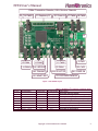
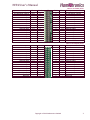
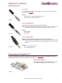
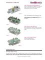
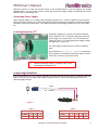
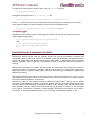
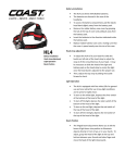
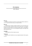
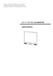
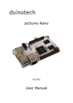
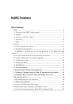
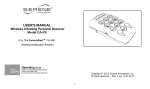
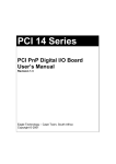
HIT4 User's Manual Dear Customer Thank you for choosing one of our products. We hope that you will be completely satisfied with this extension board and that it fully meets your expectations. This manual has been compiled in order to provide you with all the information you need to get acquainted with the board and use it efficiently. Check Your Board Upon receipt of the shipment, please immediately inspect the goods. Unless you provide a written notice to Hamletronics Limited of any claim for lack, defect or dissatisfaction with the goods, within fourteen (14) days following receipt of the shipment, such goods shall be deemed definitively inspected, checked and accepted, the absence of notification being deemed a waiver of any such claims. Operating Conditions Parameter Operating temperature range Storage temperature range DC supply voltage Maximum continuous current in J1-J8 Maximum peak current in J1-J8, (t<100ms) Total peak current in all J1-J8 Maximum input voltage on J9,J10, P4, P5 Maximum load current in P4, P5 pins Min 0 -25 4.5 -0.9 Max 85 85 12.0 200 500 2500 3.6 24 Unit °C °C V mA mA mA V mA Connectors and Board Layout Board Features HIT4 board layout is given on Figure 1. The board contains the following features: Photo detector IC1: IR receiver channel CAP0 (corresponds to /dev/irt0 device) Barrel 3.5mm connectors J1-J8: IR transmitter channels PWM0-PWM7 correspondingly Barrel 3.5mm connectors J9, J10: IR receiver channels CAP1, CAP2 correspondingly Barrel 5.5mm/2.5mm power connector J11 P1 connector mating with Raspberry Pi©1 P1 connector (please refer to Table 1 for details) P3 footprint for an optional DC/DC convertor P4 footprint for an External I/O Ports (please refer to Table 3 for details) P5 header with External I/O Ports (please refer to Table 2 for details) HL1 - green LED indicating "Power On" HL2 - yellow LED indicating "Heartbeat" (1 Hz pulse when in operable state) HL3 - red LED indicating reception of input signal on any CAPx channel HL4 - yellow LED indicating data communication with Raspberry Pi© HL5 - green LED indicating signal transmission on any PWMx channel 1 Trademark note: Raspberry Pi® is a trademark of the Raspberry Pi Foundation Copyright © 2014 Hamletronics Limited 1 HIT4 User's Manual PWMx: Transmitter Channles; CAPx: Receiver Channels P5 J6–PWM5 P1–Raspberry Pi J11–Power In J8–PWM6 J7–PWM6 P3 J5–PWM4 J4–PWM3 J9–CAP1 J1–PWM0 J3–PWM2 J2–PWM1 HL3–RECEIVE HL5–TRANSMIT HL4–SPI ACTIVE HL2–HEART BEAT J10–CAP2 HL1–POWER ON IC1–CAP0 Photo Detector Figure 1. HIT4 Board Layout Table 1. Raspberry Pi© P1/HIT4-P1 connector pinout P1 Pin 7 11 12 13 19 21 23 24 24 Pi-Designator GPIO4 GPIO17 GPIO18 GPIO27 GPIO10 (MOSI) GPIO9 (MISO) GPIO11 (SCLK) GPIO8 (CE0) GPIO7 (CE1) Pi-Direction IN OUT IN OUT OUT IN OUT OUT OUT HIT-Designator INT_O RST_N INT_O RST_N MOSI MISO SCLK CE0 CE1 Description Alternate interrupt output Alternate reset signal (active low, pull up) Primary interrupt output Primary reset signal (active low, pull up) SPI Master Output Slave Input SPI Master Input Slave Output SPI Clock Primary SPI Chip Enable Alternate SPI Chip Enable Copyright © 2014 Hamletronics Limited 2 HIT4 User's Manual Table 2. P5 Header pinout Description IR transmitter channel IR transmitter channel Discrete output Discrete output Discrete output Discrete output Discrete output Discrete output Discrete input Discrete input Discrete input Discrete input Discrete input Discrete input IR receiver channel Ground Func. PWM11 PWM9 DO11 DO9 DO7 DO5 DO3 DO1 DI11 DI9 DI7 DI5 DI3 DI1 CAP3 GND Pin # 32 30 28 26 24 22 20 18 16 14 12 10 8 6 4 2 P5 Description Power rail PWR Power rail 3.3V Discrete input Discrete input Discrete input Discrete input Discrete input Discrete input Discrete output Discrete output Discrete output Discrete output Discrete output Discrete output Reserved Reserved Func. PWR 3V3 DI12 DI14 DI16 DI18 DI22 DI24 DO12 DO14 DO16 DO18 DO20 DO22 - Pin # 1 3 5 7 9 11 13 15 17 19 21 23 25 27 29 31 P4 Pin # 31 29 27 25 23 21 19 17 15 13 11 9 7 5 3 1 Func. Pin # 2 4 6 8 10 12 14 16 18 20 22 24 26 28 30 32 Func. GND CAP0 DI13 DI15 DI17 DI19 DI21 DI23 DO13 DO15 DO17 DO19 DO21 DO23 - DO10 DO8 DO6 DO4 DO2 DO0 DI10 DI8 DI6 DI4 DI2 DI0 3V3 PWR Description IR transmitter channel IR transmitter channel Discrete output Discrete output Discrete output Discrete output Discrete output Discrete output Discrete input Discrete input Discrete input Discrete input Discrete input Discrete input Power rail 3.3V Power rail PWR Table 3. P4 Footprint pinout Copyright © 2014 Hamletronics Limited Description Ground IR receiver channel Discrete input Discrete input Discrete input Discrete input Discrete input Discrete input Discrete output Discrete output Discrete output Discrete output Discrete output Discrete output Reserved Reserved 3 HIT4 User's Manual Mating Connectors J11 - Power J11 connector mates with a barrel plug 5.5 mm outer dia, 2.5 mm inner dia, such as CUI Inc PP3-002B. Pinout: Outer contact - ground, negative power rail Inner contact - positive power rail Figure 2 J9, J10 - IR signal input These barrel connectors mate with stereo jack 3.5mm. Note: The distance between J9 and J10 is 11 mm on axes. If two jacks are used at the same time, their body dia should not exceed 11 mm Figure 3 Pinout: sleeve - GND ring - signal tip - 3.3V J1- J8 - IR signal input These barrel connectors mate with mono (or stereo) jack 3.5mm. Note: The distance between adjacent connectors is 10 mm on axes. If two jacks are used at the same time, their body dia should not exceed 10 mm Figure 4 Pinout: sleeve - signal (open drain) tip - power supply rail Mounting Board to Raspberry Pi© For secure mounting HIT board we recommend our mounting kit KIT1-IT-A01 (not included). The kit has two M3 16mm spacers, four M3 4 mm spacers and a bump-on. Step 1. Mount Bumpon Tear off protective film from the bump-on and stick the bumpon to Raspberry Pi©’s LAN connector. Figure 5 Copyright © 2014 Hamletronics Limited 4 HIT4 User's Manual Step 2. Mount spacers on the Raspberry Pi© Insert two 4mm spacers into Raspberry Pi© mounting holes from the bottom of the board. Screw both 16mm spacers as shown on the image. Figure 6 Step 3. Attach HIT board to the Raspberry Pi© Attach the HIT board to the Raspberry Pi© board by inserting Raspberry Pi©'s P1header to HIT P1 receptacle Figure 7 Step 4. Screw the top-right spacer We recommend first screwing a spacer on the right, using the other spacer as a helper, as shown on the image Figure 8 Step 5. Screw the top-left spacer Screw the remaining spacer. The HIT board is now mounted. Figure 9 Connecting Power Selecting Supply Voltage The board can be powered with DC supply voltage in range 4.5-12V. The transmission signal paths are designed to achieve 200 mA on a typical IR led with supply voltage at 5V level. This is done with onboard 22 Ohm resistors. If you are using single IR LED emitters with lower permitted forward current, you should Copyright © 2014 Hamletronics Limited 5 HIT4 User's Manual add series resistors to limit the forward current at the permitted level. If your IR emitters are already equipped with a current limiting resistor, power the board with supply voltage recommended for the IR emitters (but not exceeding 12V). Connecting Power Supply Connect power supply to J11. Please refer to Mating Connectors/J11 - Power for details on the connector. When the board is powered, HL1 LED should light up and HL2 led should start blinking, indicating operational status of the board. Please note - HL2 does not blink if the reset signal (GPIO27, pin 13 on P1) is kept low. Powering Raspberry Pi© By default, Raspberry Pi© power rails are disconnected from the board’s rails. If you power the board with a 5V power supply, you can shunt pin 1-3 of P3 connector as shown on Figure 11. This will apply power supply voltage to Raspberry Pi© power rails. For other supply voltages a DC/DC converter should be used. We recommend OKI-78SR-5/1.5-W36H-C from Murata Power Solutions. The board has sufficient space to mount this DC/DC converter on the spare space Figure 10 Note: DC current from P3 bypasses the Raspberry Pi ©’s fuse. Therefore improper voltage, if applied to pin 3 of P3 may damage the Raspberry Pi© Connecting IR Emitters Connect IR emitters to J1-J8. IR emitters should have wiring as shown on the Figure 11. Optional resistor R limits current as listed in Table 4 with supply voltage at 5V level. Table 5 lists estimated currents for different supply voltages. Anode Cathode R Figure 11 Table 4 V supply = 5V R, Ohm 0 22 I, mA 170 80 Table 5 47 50 V supply I, mA Copyright © 2014 Hamletronics Limited R=0 5 6 170 210 9 350 12 460 6 HIT4 User's Manual Connecting IR Photo-Sensors Connect external photo sensors to J9, J10 as shown on Figure 12. The photo sensors could be either with carrier out or with demodulator. The latte ones are normally tuned to a certain carrier frequency and reject signal with other carrier frequencies. Signal form additional sensor can be connected to pin 4 on P5 header. 3.3V - Tip Signal - Ring GND - Sleeve Figure 12 Installing Software Download and flash raspbian image We recommend Raspbian or minibian for using with HIT boards. Raspbian: http://downloads.raspberrypi.org/raspbian/images/raspbian-2014-01-09/2014-01-07-wheezy-raspbian.zip Minibian: http://heanet.dl.sourceforge.net/project/minibian/2013-10-13-wheezy-minibian.tar.gz Please follow Raspberry Pi© guide on flashing on of these images to an SD card. Once flashing is done, insert the flashed SD to your Raspberry Pi©, connect it to Internet and boot it. Installing Hamletronics Software 1. Login to Raspberry Pi© either via console or ssh. 2. Download packages from Hamletronics site by executing the following command or in other convenient way $ wget http://hamletronics.com/repo/linux-image-3.6.11hit+_1.0_armhf.deb \ http://hamletronics.com/repo/hit4_1.0_armhf.deb \ http://hamletronics.com/repo/spe_1.0_armhf.deb 3. Obtain root privileges (if not logged is as root) $ sudo su 4. Install Hamletronics packages Copyright © 2014 Hamletronics Limited 7 HIT4 User's Manual # dpkg --install linux-image-3.6.11hit+_1.0_armhf.deb \ hit4_1.0_armhf.deb \ spe_1.0_armhf.deb The spe package will prompt to accept Hamletronics Proprietary License. Full text of the license can be found on this link: http://hamletronics.com/repo/Hamletronics-Proprietary-License.pdf Shortly – this license grants rights to use the software from package spe with Hamletronics products only. The other package - hit4 is distributed on dual GPLv2/BSD license terms. 5. Replace the stock kernel with newly installed and reboot (provided kernel image releases spi bus for the Hamletronics driver). # mv /boot/kernel.img /boot/kernel.img.old # mv /boot/vmlinuz-3.6.11hit+ /boot/kernel.img # reboot 6. After rebooting login again and check the results: # uname -sr Linux 3.6.11hit+ # cat /sys/devices/hit/hit/hit0.0/model HIT4-RP-A10.57 Installing LIRC LIRC is a package for decoding IR signals (please refer to http://www.lirc.org/ for details). 1. Obtain root privileges (if not logged is as root) $ sudo su 2. Install lirc package # apt-get update # apt-get install lirc Configuring Software Remote Control Files Great variety of remote control files is available in the lirc repository: http://lirc.sourceforge.net/remotes/. Learning a Remote If no suitable remote control available, you may record your remote with irrecord. Start irrecord with the following command and follow instructions printed on the screen $ irrecord -n -d /dev/irt0 myremote Configuring irc* devices To create irc0 device associated with pwm0 transmitter channel (J1 connector) execute the following command: # irc-config --pwm0 --irc0 --lirc myremote myremote:: note:OK:irc0:myremote: myremote:: note:OK:irc0:myremote:18 Copyright © 2014 Hamletronics Limited 8 HIT4 User's Manual To make this irc0 device auto-created on boot, copy it to /etc/hit directory # cp myremote /etc/hit/ and append configuration line to /etc/hit/irc.conf file # echo "--pwm0 --irc0 --lirc myremote" >> /etc/hit/irc.conf To test irc device, attach an emitter to associated transmitter channel (J1/pwm0) and write a repeat count (positive number) to a remote command, created from the configuration file: $ echo 3 > /sys/devices/hit/irc/irc0/commands/POWERON Configuring gpio Hamletronics driver exposes Linux’s standard gpiochip interface, all discrete input/output pins can be made available via gpio export. # cat /sys/devices/hit/hit/hit0.0/gpiochip/base 208 # echo 208 > /sys/class/gpio/export # cat /sys/class/gpio/gpio208/value 0 Limited Warranty & Limitation of Liability Hamletronics Limited warrants that the hardware product will be free from defects in material and workmanship under normal use for a period of 12 month from the date of shipment. This warranty extends only to the original buyer and does not apply to any product which, in Hamletronics' opinion, has been misused, improperly altered, neglected or damaged by accident or abnormal conditions of operation or handling. Hamletronics Limited does not warrant that the product will interoperate with a third-party product or third-party software. This warranty is limited to ability of the product (1) to capture input signal in the digital form, and (2) to generate output signals from input data according to specifications, published by Hamletronics Limited. This limited hardware warranty does not cover the software. Software is provided "as is," and in no event does Hamletronics Limited warrant that the software is error free or that customer will be able to operate the software without problems or interruptions. Hamletronics makes no other express warranties except as provided herein, and any and all implied warranties of merchantability or fitness for particular purpose shall only be in effect during the 12 month warranty period provided hereunder. Hamletronics' liability on any warranty claim shall be limited to the actual purchase price paid. Hamletronics Limited shall not be responsible to customer or any third party for any special, consequential, incidental or indirect damages, including but not limited to loss of profits, loss of data, or data being rendered inaccurate, loss of revenues, sales, business, goodwill or use. Copyright © 2014 Hamletronics Limited 9