1
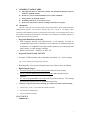
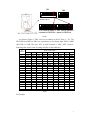
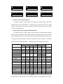
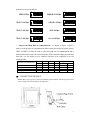
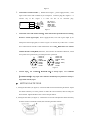
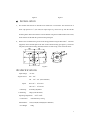
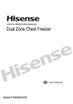
MEDIUM DUTY
PAN/TILT UNIT
V1.1
Please read the operation manual carefully
before installing and using
SAFETY PRECAUTIONS
CAUTI ON
RI SK OF ELECTRI C
SHOCK. DO NOT OPEN!
CAUTI ON:
TO REDUCE THE RI SK OF ELECTRI CAL SHOCK, DO DOT
OPEN COVERS. NO USER SERVI CEABLE PARTS I NSI DE.
REFER SERVI CI NG TO QUALI FI ED SERVI CE PERSONNEL
The l i ght i ng f l ash wi t h a ar r owhead symbol , i n an
equi l at er al t r i angl e, i s i nt ended t o al er t t he user .
Ther e i s uni nsul at ed “ danger ous vol t age” pr esence
near by t he pr oduct ' s encl osur e whi ch may be r i sk of
t o per sons .
The excl amat i on poi nt wi t hi n an equi l at er al
t r i angl e i s i nt ended t o al er t t he user t o r ef er ence
of t he i mpor t ant oper at i ng and mai nt enance
( ser vi ci ng ) i nst r uct i ons .
THE PRODUCT CODE MARKED ON THE BOTTOM COVER. PLEASE
FI LL THE CODE I N THE FOLLOWI NG BLANK. PLEASE SAVI NG
THI S SPECI FI CATI ON CAREFULLY, SO THAT CHECKI NG.
MODEL: ________________________
PRODUCT CODE: ________________________
INDEX
I. IMPORTANT SAFEGUARDS……………………………………1
II. Summarize………………………………………………………..1
III. Setting of P/T……………………………………………………….1
3.1
Address setting of P/T ……………………………………….1
3.2 Setting of terminal resistance…………………………………2
3.3 Setting of communication protocol…………………………2
3.4 Setting of baud rate…………………………………………….3
IV. CONNECTION DETAILS……………………………………….4
4.1 Connection P/T with controller……………………………..5
4.2 Connection P/T with outdoor housing………………………..5
4.3 Control wiper…………………………………………………..5
V. SETTING PAN/TILT END………………………………….5
5.1 S e t t i n g
the Pan limits……………………………5
5.2 S e t t i n g
t h e T I LT l i m i t s … … … … … … … … … … . . 5
VI. Installation……………………………………………………..6
VII.
SPECIFICATIONS……………………………………………6
I.
IMPORTANT SAFEGUARDS
a)
b)
c)
d)
e)
This apparatus must be connected to Earth. This installation should be made by
made by a qualified installer.
Do not carry out electrical installations in wet weather conditions.
Voltage must to be matched with P/T.
Examining connection , to sure that is correct.
Please not to put the P/T with auto scanning continuouly for long time.
II. Summarize
This unit is a hi-tech CCTV product which incorporates panoramic speed-variable PAN/TILT,
multifunctional decoder, CPU processor, memory chip into a whole. It can largely reduce
connection and installation processes of components in the system, rise up reliability of the system
and facilitate installation and maintenance. Therefore it has advantages of beautiful appearance,
compact structure and easy operation.
Integrated Multi-Protocol Decoder
a. With integrated decoder and multi-protocol, it can integrate 16 kinds of
communication protocols in maximum. As its baud rate of communication can
be adjusted, it is compatible with many normal systems by easy setup inside the
dome camera, so it has stronger versatility.
b. RS485 serial control: addresses of unit 1-511.
1、
2、
Integrated Speed-Variable PAN/TILT
a. Turning 0--355ºhorizontally and an adjustable speed from 0.25 - 10 rad/s; turning
-90 -- +20º vertically with a speed up to 10 rad/s.
b. Running stably at low speed with super lower noise. Pictures have no shaking.
3、
a.
High Intelligent Degree
As much as 64 preset positions can be preset with powerless memory
b. The P/T can scan horizontally between two points and scan speed can be
modified.
c. Six sets of programmable tour locus with 16 position each set. The running
speed and the detention time are adjustable respectively;
4、 Could to be cooprated with outdoor housing ,also could control camera that in housing
a.
Camera’s iris、focus、zoon could to be manual controlled.
b. Control auto iris shutter speed.
c.
Auto white balance tracking.
III. P/T SETUP
1、 ADDRESS SET
1
SW1
SW2
ON
ON
1
2
3
4
5
6 7
8
9 10
1
DI P- - DI P9:
Addr ess Sel ect
2
3
4
5
6
Pr ot ocol Sel ect
ON
ON
1
2
3
4
5
6 7
8
1
9 10
2
3
4
5
6 7
8
9 10
120Ω terminal resistor is 120Ω terminal resistor is
connected on RS485 Bus opened for RS485 bus
Figure 1
As shown in Figure 1, SW1 is used to set address of the P/T from 1 – 511. The
ID-CODE from DIP-9 to DIP-1 are equivalent to a 9-bit binary digit. DIP-9 is MSB
while DIP-1 is LSB. The state “ON” of each bit means 1 while “OFF” means 0.
Following table shows states of coding switches of some addresses.
P/T
Address
Status of ID-CODE
1
2
3
4
5
6
7
8
9
10
11
12
13
14
15
16
17
18
DIP1
ON
OFF
ON
OFF
ON
OFF
ON
OFF
ON
OFF
ON
OFF
ON
OFF
ON
OFF
ON
OFF
DIP2
OFF
ON
ON
OFF
OFF
ON
ON
OFF
OFF
ON
ON
OFF
OFF
ON
ON
OFF
OFF
ON
DIP3
OFF
OFF
OFF
ON
ON
ON
ON
OFF
OFF
OFF
OFF
ON
ON
ON
ON
OFF
OFF
OFF
…
511
…
ON
…
ON
…
ON
DIP4
OFF
OFF
OFF
OFF
OFF
OFF
OFF
ON
ON
ON
ON
ON
ON
ON
ON
OFF
OFF
OFF
…
ON
Table 1
DIP5
OFF
OFF
OFF
OFF
OFF
OFF
OFF
OFF
OFF
OFF
OFF
OFF
OFF
OFF
OFF
ON
ON
ON
DIP6
OFF
OFF
OFF
OFF
OFF
OFF
OFF
OFF
OFF
OFF
OFF
OFF
OFF
OFF
OFF
OFF
OFF
OFF
DIP7
OFF
OFF
OFF
OFF
OFF
OFF
OFF
OFF
OFF
OFF
OFF
OFF
OFF
OFF
OFF
OFF
OFF
OFF
DIP8
OFF
OFF
OFF
OFF
OFF
OFF
OFF
OFF
OFF
OFF
OFF
OFF
OFF
OFF
OFF
OFF
OFF
OFF
DIP9
OFF
OFF
OFF
OFF
OFF
OFF
OFF
OFF
OFF
OFF
OFF
OFF
OFF
OFF
OFF
OFF
OFF
OFF
…
ON
…
ON
…
ON
…
ON
…
ON
For Example:
2
ON
ON
1
2
3
4
5
6 7
8
ON
1
9 10
P/ T Addr ess=1
ON
3
4
5
6 7
8
1
9 10
2
3
4
5
6 7
8
9 10
2
3
4
5
6 7
8
9 10
P/ T Addr ess=3
ON
1
ON
1
P/ T Addr ess=4
2、
2
P/ T Addr ess=2
2
3
4
5
6 7
8
9 10
1
P/ T Addr ess=5
2
3
4
5
6 7
8
9 10
P/ T Addr ess=511
Selection of the Terminal Resistor
As shown in Figure 1, DIP10 of the ID-CODE is the select switch of the 120Ω
terminal resistor on the bus RS485, on which only one terminal resistor of the dome
camera at the farthest end can be connected, while the terminal resistors of other
devices should be opened.
3、
Setup of the Protocol and the Default Baud Rate
As shown in Figure 1, SW2 is used to set the protocol of communication and the
baud rate used by the dome camera. DIP-4 to DIP-1 of SW2 is used to select protocols
and 16 different protocols can be selected in maximum. Following table shows states
of coding switches of protocols selected by the dome camera in which
protocol has been integrated while
○
●
means the
means the protocol is temporarily vacant.
Selection of Protocols
Normal Baud Rate
DIP1
DIP2
DIP3
DIP4
DIP5
DIP6
Integrated
Protocol
SAMSUNG
ON
OFF
OFF
OFF
OFF
ON
●
NEON
ON
OFF
OFF
OFF
OFF
ON
●
Reserved
OFF
ON
OFF
OFF
OFF
ON
○
PELCO-D
PELCO-P/4800
PELCO-P/9600
PANASONIC
ON
ON
OFF
OFF
OFF
ON
OFF
ON
OFF
ON
OFF
OFF
OFF
ON
ON
●
OFF
OFF
ON
OFF
OFF
Longcomity
OFF
ON
ON
OFF
OFF
ON
●
HUNDA600
ON
ON
ON
OFF
OFF
ON
●
LILIN
OFF
OFF
OFF
ON
ON
OFF
○
VICON
ON
OFF
OFF
ON
ON
OFF
○
MOLYNX
OFF
ON
OFF
ON
OFF
ON
○
KALATEL
ON
ON
OFF
ON
ON
OFF
○
VCL
OFF
OFF
ON
ON
OFF
ON
○
DAIWA
ON
OFF
ON
ON
OFF
ON
●
ALEC
OFF
ON
ON
ON
OFF
ON
●
Ultrak
ON
ON
ON
ON
OFF
ON
●
Type of Protocols
●
○
Table 2
Some protocols and the states of the coding switches of normal baud rate of these
3
protocols are shown as follows:
ON
NEON/ 9600Bps
ON
1
2
3
4
5
PANASONI C/ 9600Bps
6
ON
PELCO- D/ 2400Bps
2
3
4
5
KALATEL/ 4800Bps
6
ON
4、
3
4
5
6
1
2
3
4
5
6
1
2
3
4
5
6
1
2
3
4
5
6
ON
1
2
3
4
5
ALEC/ 9600Bps
6
ON
PELCO- P/ 9600Bps
2
ON
1
PELCO- P/ 4800Bps
1
ON
1
2
3
4
5
Ul t r ak/ 9600Bps
6
Setup of the Baud Rate of Communication.
As shown in Figure 1, SW2 is
used to set the protocol of communication and the baud rate used by the dome camera.
DIP-6 and DIP-5 of SW2 are used to select the baud rate of communication and 4
different baud rates can be selected in maximum. If the controller adopts non-standard
baud rate, you can adjust it to be identical with that of the controller as per the
following table.
Baud Rate of Communication
DIP-1
DIP-2
2400bps
4800bps
9600bps
19200bps
DIP-3
DIP-4
Setup of Baud Rate
DIP-5
DIP-6
OFF
OFF
ON
OFF
OFF
ON
ON
ON
Table 3
Ⅳ. CONNECTION DETAILS
Notice: Before carrying out any electrical installation ensure that the cable being used in at the
correct voltage and current rating for the application.
4
Figure 2
1.
Connection P/T with controller : RS485 control signal 、power supply(AC24V)、video
signal could connect with controller by air waterproof connector plug (D1). Figure 4 is
Connect
way
of
D1.
Figure
3
is
come
out
line
of
air
connector
plug.
RED: AC24V I N
BLACK: AC24V I N
ORANGE: RS485+
YELLOW: RS485VI DEO: VI DEO OUT
RED
BLACK
ORANGE
YELLOW
VI DEO
Figure 3
2.
Connection of P/T and outdoor housing:when collocate the special decoder for housing,
decoder’s control signal input、Power supply(AC24V) and video signal output by air
waterproof connector plug (D2) to conncet . Figure 5 is connect way of D2. Note:Connect
P/T’s GND with lens decoder’s GND. Furthermore P/T’s TXD、RXD must cross connect
with lens decoder’s TXD、RXD,Otherwise,lens will not to be controlled. Otherwise,Could
not to preset lens’s position,only just could preset P/T’s postision.
D1
2
1
4
5
7
3
6
1. AC24V I N
2. AC24V I N
3. RS4854. CABI NET GND
5. RS485+
6. VI DEO+
7. VI DEO-
Figure 4
3.
D2
2
1
4
5
7
3
6
1. AC24V OUT
2. AC24V OUT
3. TXD( TTL LEVEL)
4. GND
5. RXD( TTL LEVEL)
6. VI DEO+
7. VI DEO-
Figure 5
Control wiper:Use command(D-ZOOM ON)to startup wiper;Use command
(D-ZOOM OFF)to stop wiper. Also could use call NO.64 preset position to startup or
stop(switch controll) wiper.
Ⅴ . SETTING PAN/TILT END
a、 Setting the Pan limits (see figure 6)::Loosen the M4 screws and loosen the pan strikers. Adjust
the strikers until they are at the position to strike the relevant actuator, thus activating the
limit switches. Tighten the M4 screws to secure the pan strikers.
b、Setting the Tilt limits (see figure 7):Release the screw locks and adjust the strikers until they
are at the position to strike the actuator, thus activating the limit switches.
5
Figure 6
Ⅵ.
Figure 7
INSTALLATION
a、 This outdoor Pan/Tilt unit is intended to be mounted on a wall mount. The unit base has 4
holes equi-spaced on 4″ (101.6mm) P.C.D[see figure 8], which line up with the bracket
mounting holes. Mount the unit base onto the bracket using the four M6×25 Hex head screws,
6mm washers and the M6 nuts provided in the packing kit.
b、 Remove the six M4mm fixing screws from the top platform using the three M1/4″ -20screws
(supplied). Secure the Sub-plate to the base of the Camera Housing [see figure 1]. Secure the
sub-plate (with camera housing attached) with the six 6mm fixing screws removed earlier.
Figure 8
Ⅶ. SPECIFICATIONS
Input Voltage:
Angular Travel:
AC 24V
Pan 350°
Tilt +20°~ -90° (OTT MOUNT)
Speed:
Pan 0.25°~ 10°/second
Tilt 0.25°~ 10°/second
Limit Stop:
Load Rating:
Externally adjustable
15Kgs (OTT MOUNT)
Operating Temperature: -35℃~+60℃
Construction:
Measurement:
Unit Weight:
Aluminum alloy casting
225(L)×180(W)×260(H)(OTT MOUNT)
10 Kg
6