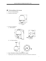
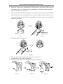
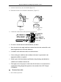
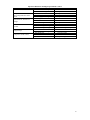
1
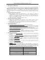
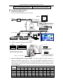
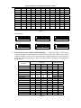
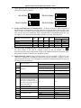
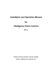
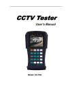
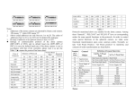
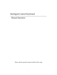
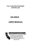
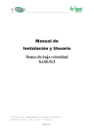
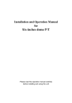
Installation and Operation Manual
for
Six inches Middle-Speed Dome P/T
V1.1
Please read the operation manual carefully
before installing and using this unit
Operation Manual for Intelligent Speed Dome Camera
I. Points for Attention
1. Please read the operation manual carefully before installing and operating the product.
2. The product takes power supply of AC24V. The rated input voltage of the camera is
marked on the base or other corresponding place.
3. During the course of transportation, storage and installation, the product should be avoided
from incorrect operations such as heavy pressing, strong vibration etc., which can cause
damage of product as there are sophisticated optical and electronic devices inside the
machine.
4. Do not attempt to disassemble the camera. In order to prevent electric shock, do not
remove screws or covers. There are no user-serviceable parts inside.
5. Always follow all electrical standards for safety when it is in operation. Adopt the
particular power supply which is provided with the unit. RS-485 and video signal should
keep enough distance with high voltage equipments and cables when they are in
transmission. Precautions for anti-lightning and anti-surging should be taken if necessary.
6. Do not operate it in case temperature, humidity and power supply are beyond the limited
stipulations.
7. Do not let the camera aim at the sun or the object with extreme light whatsoever it is
switched on or not. Do not let the camera aim at or monitor bright and standstill object for
a long time.
8. Do not use aggressive detergent to clean the main body of the camera. Wipe dirt with dry
cloth. If needed, mild detergent can be used suitably.
9. Operate the intelligent speed dome camera with great care to avoid shock or vibration. It
operate incorrectly, the Speed Dome could be damaged
10. Be careful to avoid to crash, Never mount the unit on a ceiling that cannot support its
weight.
11. If necessary, use a commercial lens cleaning paper to clear the lens windows. Gently wipe
the lens window until clean.
1
Operation Manual for Intelligent Speed Dome Camera
II. Description of Functions
The intelligent dome camera is a hi-tech CCTV product which incorporates high-clarity
color camera, panoramic speed-variable PAN/TILT, multifunctional decoder, CPU processor,
memory chip into a whole. It can largely reduce connection and installation processes of
components in the system, rise up reliability of the system and facilitate installation and
maintenance. Therefore it has advantages of beautiful appearance, compact structure and easy
operation.
1. Integrated Multi-Protocol Decoder
a. With integrated decoder and multi-protocol, it can integrate 16 kinds of
communication protocols in maximum. As its baud rate of communication can be
adjusted, it is compatible with many normal systems by easy setup inside the dome
camera, so it has stronger versatility.
b. RS485 serial control: addresses of camera 1-1023.
2. Integrated speed-variable PAN/TILT
a. Turning 360 º horizontally and continuously with unlimited positions and an
adjustable speed from 0.2 -- 80rad/s; turning 0 - 90º vertically with a speed up to 12 rad/s.
b. Running stably at low speed with super lower noise. Pictures have no shaking.
c. the location precision up to ±0.2°.
3. High Intelligent Degree
a. As much as 64 preset positions can be preset with powerless memory;
b. The camera can scan horizontally between two points and scan speed can be modified.
The positions of linear scan are optional and the dome camera can scan the range
larger or smaller than 180° between any two points with adjustable speed;
c. Six sets of programmable patrol with 16 position each set. The running speed and the
detention time are adjustable respectively;
d. The Integrated Multi-Protocol. Multiple communication protocols are integrated
inside the dome camera with selectable baud rate from 2400 bps to 9200 bps.
4. Functions of the Camera
a. Description of the Focus Control Mode: the user can adjust the focus of the camera
manually.
b. Description of Backlight Compensation: when the object to be shot is dark and
looks dim, the user can open the backlight compensation according to actual need.
c. Description of White Balance: when the image has color distort on the screen, the
user can set different modes by orders.
d. Description of ZOOM Control: user can “pull near” or “push far” the lens according
to actual conditions.
e. Description of Electronic Shutter: it is fixed on 1/50 sec after initialization when the
camera is switched on.
f. AE Mode: setup of Manual/Automatic.
g. Minimum illumination: it is used only when the external brightness is extremely low.
Normally the camera works on the automatic state. In case the external brightness is
lower than 1Lux, the camera can be switch to the Minimum illumination state
automatically You can also set the Minimum illumination state manually.
Minimum illumination
LENS
16x
18x
f =3.9 to 63mm (F1.6 DC Iris)
f =4.1 to 73.8 mm (F1.4 to F3.0)
1 Lux (common) / 0.01 Lux(B & W)
1 Lux (F1.6)
22x
f =4 to 88 mm (F1.6 to F3.8)
0.2 Lux(F1.6 1/3s)
23x
f =3.6 to 82.8 mm (F1.6 to F3.7)
0.01 Lux(B & W)
26x
f =3.5 to 91 mm (F1.6 to F3.8)
0.01 Lux(B & W)
2
Operation Manual for Intelligent Speed Dome Camera
27x
f =3.6 to 98 mm (F1.5 to F3.8)
1 Lux (Common / 0.01 Lux(B & W)
Ⅲ . Setup of the Dome Camera
1. Connection of the System
1) The Systematic Drawing of the Dome Camera
C
Moni t or
Power I N
AC24V OUT
Power I N
VI DEO OUT
RS- 485
Power Adapt er
Mul t i pl exer
Mat r i x
Dome Camer a
RS- 485
Pr ot ocol Adapt er
RS- 485
AD Mat r i x
RS- 485
RS- 485
Code Conver t er
Pr ot ocol Adapt er
BSW
BSW
V
RS232
Phi l i ps Mat r i x
Figure 1
2) Address / Protocol Coding Switch Drawing
SW2
SW1
ON
1 2 3
JP
ON
1
2
3
4
5
6
Pr ot ocol Set
1
2
3
4
5
6 7
8
9 10
120Ω terminal resistor is
opened for RS485 bus
1 2 3
Addr ess Set
SW2: DI P1- - DI P4 Sel ect Pr ot ocol
SW2: DI P5- - DI P6 Sel ect Baud Rat e
JP
120Ω terminal resistor is
connected on RS485 Bus
Br acket f or f i xed camer a
Figure 2
2. Setup of Coding Switch of Dome Camera. As shown in Figure 2, SW1 is used to set
address of the dome camera from 1 – 1023. The ID-CODE from DIP-10 to DIP-1 are
equivalent to a 10-bit binary digit. DIP-10 is MSB while DIP-1 is LSB. The state “ON” of
each bit means 1 while “OFF” means 0. Following table shows states of coding switches
of some addresses.
Dome
Address
1
2
3
4
5
6
7
DIP-1
ON
OFF
ON
OFF
ON
OFF
ON
DIP-2
OFF
ON
ON
OFF
OFF
ON
ON
DIP-3
OFF
OFF
OFF
ON
ON
ON
ON
DIP-4
OFF
OFF
OFF
OFF
OFF
OFF
OFF
ID-CODE Status
DIP-5 DIP-6 DIP-7
OFF
OFF
OFF
OFF
OFF
OFF
OFF
OFF
OFF
OFF
OFF
OFF
OFF
OFF
OFF
OFF
OFF
OFF
OFF
OFF
OFF
DIP-8
OFF
OFF
OFF
OFF
OFF
OFF
OFF
DIP-9
OFF
OFF
OFF
OFF
OFF
OFF
OFF
DIP-10
OFF
OFF
OFF
OFF
OFF
OFF
OFF
3
Operation Manual for Intelligent Speed Dome Camera
8
9
10
11
12
13
14
15
16
17
18
OFF
ON
OFF
ON
OFF
ON
OFF
ON
OFF
ON
OFF
OFF
OFF
ON
ON
OFF
OFF
ON
ON
OFF
OFF
ON
OFF
OFF
OFF
OFF
ON
ON
ON
ON
OFF
OFF
OFF
ON
ON
ON
ON
ON
ON
ON
ON
OFF
OFF
OFF
OFF
OFF
OFF
OFF
OFF
OFF
OFF
OFF
ON
ON
ON
OFF
OFF
OFF
OFF
OFF
OFF
OFF
OFF
OFF
OFF
OFF
OFF
OFF
OFF
OFF
OFF
OFF
OFF
OFF
OFF
OFF
OFF
OFF
OFF
OFF
OFF
OFF
OFF
OFF
OFF
OFF
OFF
OFF
OFF
OFF
OFF
OFF
OFF
OFF
OFF
OFF
OFF
OFF
OFF
OFF
OFF
OFF
OFF
OFF
OFF
OFF
OFF
OFF
OFF
OFF
…
1023
…
ON
…
ON
…
ON
…
ON
…
ON
…
ON
…
ON
…
ON
…
ON
…
ON
Table 1
For Example:
ON
ON
1
2
3
4
5
6 7
8
9 10
ON
1
2
3
4
5
6 7
8
9 10
1
2
3
4
5
6 7
8
9 10
Speed Dome Addr ess=1
Speed Dome Addr ess=2
Speed Dome Addr ess=3
ON
ON
ON
1
2
3
4
5
6 7
8
9 10
1
Speed Dome Addr ess=4
2
3
4
5
6 7
8
9 10
Speed Dome Addr ess=18
1
2
3
4
5
6 7
8
9 10
Speed Dome Addr ess=1023
3. Setup of the Protocol and the Default Baud Rate. As shown in Figure 2, SW2 is used
to set the protocol of communication and the baud rate used by the dome camera. DIP-4
to DIP-1 of SW2 is used to select protocols and 16 different protocols can be selected in
maximum. Following table shows states of coding switches of protocols selected by the
dome camera
Protocols
SAMSUNG
B01
NEON
Santachi
PELCO-D
PELCO-P/4800
PELCO-P/9600
PANASONIC
Longcomity
HUNDA600
LILIN
VICON
MOLYNX
KALATEL
VCL
Reserved
ALEC
Ultrak
DIP status
Normal Baud Rate
DIP-1
ON
ON
ON
OFF
ON
DIP-2
OFF
OFF
OFF
ON
ON
DIP-3
OFF
OFF
OFF
OFF
OFF
DIP-4
OFF
OFF
OFF
OFF
OFF
OFF
OFF
ON
OFF
ON
OFF
ON
OFF
ON
OFF
ON
OFF
ON
OFF
ON
OFF
ON
ON
OFF
OFF
ON
ON
OFF
OFF
ON
ON
ON
ON
ON
OFF
OFF
OFF
OFF
ON
ON
ON
ON
OFF
OFF
OFF
ON
ON
ON
ON
ON
ON
ON
ON
DIP-5
OFF
OFF
OFF
OFF
OFF
ON
OFF
OFF
OFF
OFF
OFF
ON
OFF
ON
OFF
OFF
OFF
OFF
DIP-6
ON
ON
ON
ON
OFF
OFF
ON
ON
ON
ON
ON
OFF
ON
OFF
ON
ON
ON
ON
Table 2
4
Operation Manual for Intelligent Speed Dome Camera
Some protocols and the states of the coding switches of normal baud rate of these
protocols are shown as follows:
ON
B01/ 9600Bps
ON
1
2
3
4
5
PELCO- P/ 4800Bps
6
ON
PELCO- D/ 2400Bps
1
2
3
4
5
6
1
2
3
4
5
6
ON
1
2
3
4
5
PELCO- P/ 9600Bps
6
4. Setup of the Baud Rate of Communication. As shown in Figure 2, SW2 is used to set
the protocol of communication and the baud rate used by the dome camera. DIP-6 and
DIP-5 of SW2 are used to select the baud rate of communication and 4 different baud
rates can be selected in maximum. If the controller adopts non-standard baud rate, you
can adjust it to be identical with that of the controller as per the following table.
Baud Rate of Communication
DIP-1
DIP-2
DIP-3
DIP-4
2400bps
4800bps
9600bps
19200bps
Setup of Baud Rate
DIP-5
DIP-6
OFF
OFF
ON
OFF
OFF
ON
ON
ON
5. Selection of the Terminal Resistor of the Dome Camera. As shown in Figure 2, JP is
the select switch of the 120 Ω terminal resistor on the bus RS485, on which
only one terminal resistor of the dome camera at the farthest end can be connected, while
the terminal resistors of other devices should be opened.
6. Special function control. Some special protocol such as “Santachi”,”PELCO-D” and
“PELCO-P” without the command of control some especial functions, in order to use the
special functions of dome, so we changed the command of calling/setting NO.51 preset to
NO.64 preset to control them.
N
Object of control
51
52
53
54
55
56
57
58
59
60
61
62
63
64
Keyboard control
Call the N position
Auto scan(low speed)
Auto scan
Camera power
Back light *
ICR shor
OSD (Some cameras have it’s
own menu, to open/close the
menu by the command “turn on
the OSD”, and use the command
“turn off the OSD” to
open/close the OSD)
Digital Zoom
FOCUS
IRIS
White Balance Mode
Preset the N position
Auto cruise
Auto scan(middle speed) Set the start point of scan
Auto scan(high speed)
Power on
On
On
Set the end point of scan
Power off
Off
Off
On
Off
On
Auto
Auto
Auto
Indoor
ATW
Off
Manual
Manual
Manual
Outdoor
One Push WB
5
Operation Manual for Intelligent Speed Dome Camera
Ⅳ. The Installation of the System
1. The style of the Installation
262
1) Dimension of the Product
Φ 152
Φ 219
Figure 3
2) The Style of Installation
a) Wall Installation
Figure 4
262
300
b) In-Ceiling Installation
Φ7
Figure 5
2. Steps of Installation (taking wall-mounting as example)
1.
Unpacking the carton and carefully take out the dome camera and its attachments.
6
Operation Manual for Intelligent Speed Dome Camera
2.
Rotate the vitreous cover counterclockwise and take out it. (see Figure 6) Note: It can be
ignored the steps 2,3,4,5 while the protocol and address are matching with the controller.
3.
Take out the black liner. (Figure 7)
4.
Based on the ID-CODE shown as Figure 2, set up the protocol used by the camera and the
baud rate as per the state according to Table 1. Check the address of the camera to see if it
is matched with that you need. If not, set the address of the dome camera at corresponding
position as per Table 1.
Takedown t he
bl ack l i ner
Open
Figure 6
5.
Figure 7
Fix the black liner (see Figure 8).
Fi xed t he
bl ack l i ner
6.
7.
8.
Figure 8
Take out the cover of the wall-mounting bracket (see Figure 9).
Fix the bracket on the wall (see Figure 10).
Drill the system control wires through the bracket (see Figure 11).
Figure 9
Figure 10
Figure 11
7
Operation Manual for Intelligent Speed Dome Camera
9.
Install the aluminum alloy ball on the bracket (Figure 12).
10. Rotate the vitreous cover clockwise and mount it(Figure 13).
Cl ose
Figure 12
Figure 13
11. Connect the control wires of the system as per Figure 14.
RED CONNECTOR
( POWER I N)
RED LI NE( AC24V I N)
BLACK LI NE( AC24V I N)
ORANGE LI NE( RS485+)
YELLOW LI NE( RS485- )
BLACK CONNECTOR
( RS485 CONTROL I N)
VI DEO OUT
Figure 14
3. To ensure a smooth and successful installation, you must:
1.
Have electrical work comply with latest national electrical code, national fire code,
and all applicable local codes and ordinances.
2.
Coordinate work with other trades to avoid interference.
3.
Verify existing site conditions and coordinate with owner’s representative and
appropriate utilities as required.
4.
Obtain copies of all related plans, specifications, shop drawings and addenda to
schedule and coordinate related work
5.
Thoroughly review the project to ensure that all work meets or exceeds the above
requirements. Bring alleged discrepancies to the attention of the CCTV Project
Coordinator.
Ⅴ.
Technical data table
1、 Indoor/Outdoor Speed Dome
8
Operation Manual for Intelligent Speed Dome Camera
Power supply
Power consumption
Sync system
Preset
Patrol
Auto pan scan
AC24V 50/60Hz
Indoor dome:12W
Internal
64 presets
6
Outdoor dome:35W
360°Programmable
Pan Manual Control Speed
0—30°/s
Pan Preset Speed
80°/s max
Pan rotation range
360°continues
Title range
Tilt 90°
Tilt speed
12°/s max(manual & preset speed)
RS485
2400/4800/9600/19200 bps
Fan & heater auto-start (only outdoor dome)
Control mode
Baud Rate
Fan & heater
Environment temp
Indoor dome:0℃ — +40℃
Outdoor dome –35℃ -- +55℃
2、 Camera Optional data table
Mode
16×
Color
Sync mode
Image Inductor
Internal
Scanning system
Resolution
Effective
Pixels
PAN
18×
Day/Night
switch
22×
Color
1/4″ Color CCD
2:1 interlacing
>470TVL
≥ 480TVL
470,000 pixels
752×582(440K)
NTSC 440,000 pixels
23×
Day/Night
switch
27×
Day/Night
switch
758×592(450K) 795×596(470K)
768×494(380K)
758×504(380K) 811×508(410K)
1Lux / 0.01Lux 0.2LuxF1.6 1/3s) 1Lux / 0.01Lux 1Lux / 0.01Lux
Sensitivity
Iris
Focus
Zoom Rate
1Lux(F1.6)
Auto/ Manual
Auto/ Manual
16× optical
f=3.9 to 63 mm
18× optical
22× optical
f=4.1 to 73.8 mm f=4 to 88 mm
23× optical
27× optical
f=3.6 to 82.8 mm f=3.6 to 98 mm
Angel of view
Wide: 47°
Wide: 48°
Wide: 47°
Wide: 54°
TELE: 2.7°
TELE: 2.2°
TELE: 2.5°
TELE: 3°
B.L compensation Auto/ Manual
White balance
Auto/ Manual
Gain Control
Auto/ Manual
Signal formal
Auto/ Manual
S/N
>46dB
Video output
Ⅵ.
≥ 50dB
1.0±0.2Vp-p
Troubleshooting
Problem
On power no action
Probable cause
Power supply fault
Solution
Replace
9
Operation Manual for Intelligent Speed Dome Camera
On power cannot self-check
have image but have motor
noise
Self-check ok, but have no
image
Self-check ok but cannot
control
Vague image
On power cannot control
Bad connection of the power
Transformer damaged
Mechanical failure
Camera incline
Power supply not enough
Video signal fault
Bad connection of the video
Camera damaged
RS485 Bus bad connection
Dome id setting is wrong
Protocol setting is wrong
Bad connection of the video
Power supply not enough
Self check error
Bad connection of control
Bad control of matrix
Make correction
Replace
Repair
Reinstall
Replace
Reinstall
Press to full connect
Replace
Check the RS485 connection
Reselect
Reset and on power again
Press to full connect
Replace
On power again
Press to full connect
On power again
10