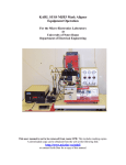
1
COBILT CA-800 Mask Aligner
Equipment Operation
For the Micro-Electronics Laboratory
At
University of Notre Dame
Department of Electrical Engineering
This user manual is not be removed from room 247A. This includes making copies. A
downloaded copy can be obtained from the web at the following link:
http://www.nd.edu/~ee/ndnf/
or contact Keith Darr for a copy of this manual.
Purpose
The Cobilt Model CA-800 Aligner is designed to allow accurate alignment of a
wafer to a mask and uniform exposure of the wafer to a source of ultraviolet
light. This machine is also available for uses as a flood exposure device, aimed
at 100% wafer exposure.
Reference Documents
Cobilt Model CA-800 Operating and Maintenance Manual
Additional Equipment Required
Light Intensity Meter Model #1000
Materials Required
Photoresist coated samples
5” contact mask (127mm X 127mm) – for use in patterning
Protective Equipment Required
Latex Gloves
Safety glasses
It is acceptable to remove safety glasses for alignments to allow proper use of the
microscope.
Engineering and/or Administrative Controls
Only authorized users may operate this piece of equipment
Training
To obtain training on this machine, please contact Keith Darr (office 221, phone
1-5497, email [email protected])
Problems
For problems, clarification of procedures, or general information pertaining to this
machine please contact one of the following personnel.
Keith Darr
Mike Thomas
Mark Richmond
631-5497
631-7493
631-6478
[email protected]
[email protected]
[email protected]
In Case of Emergency, Please Contact Notre Dame Security at
911
MSDS’s can be located in the EE Department office or in Room 244 near the door
Keith Darr
Rev 1.4
11/5/2008
2
Table of Contents
Page
4
5
6
7
8
9
9,10
10,11
11
12
13
Keith Darr
Rev 1.4
11/5/2008
Contents
Authorized Users
Standby Conditions, Preparation, Malfunctions
Operation Modes
Component Description
Start Up Procedure
Light Intensity Reading and Exposure Time Setting
Microscope Setup and Reticle Positioning
Aligning the Wafer to the Mask
Exposure
Unloading the Wafer and Completing Operation
Appendix
3
Authorized Users List
Name
Keith Darr
Rev 1.4
11/5/2008
Email
Advisor
Date
4
Standby Conditions
1.
2.
3.
4.
Stage control, micromanipulator “mouse”, in the CENTER position. (figure 4)
Lamp Power Supply OFF (figure 1)
Coblit Control Box Power OFF (figure 2)
Dosimeter OFF and on the shelf to the left of Karl Suss #1
Preparation
1. Apply and bake Photoresist as per user defined process.
2. The following steps are OPTIONAL, as they may not be appropriate for all
processes.
a. Remove any resist from the back of the sample so the wafer is flat on the
chuck and does not contaminate the chuck.
i. Wet (not soaked) a wipe with acetone and gently slide the sample
across.
b. Mask Clean
i. Working in a wet bench, Holding the edge of the reticle
ii. Spray the reticle with acetone.
iii. Spray the reticle with IPA.
iv. Rinse the reticle with DI water.
v. Blow dry the reticle with N2.
Malfunctions
If there is a problem with the function of the machine, the operator can restore the
machine to a halt condition by depressing the RESET button. (Figure 3) The aligner then
returns the wafer to the turntable and halts. If a second wafer has been loaded, the
turntable will rotate and this wafer will be brought into contact with the mask, resuming
the operation. If it is undesirable to resume the operation in this manner, the RESET
button should be held down until after the turntable has rotated into position.
Keith Darr
Rev 1.4
11/5/2008
5
Operation Modes
NORMAL OPERATION (HIGH VACUUM CONTACT SEQUENCE)
The normal operation mode allows the operator to align an unexposed wafer to a
patterned mask prior to exposure. This mode requires the use of chuck with outer edge
seals.
LOW VACUUM CONTACT SEQUENCE
The low vacuum contact sequence is identical to the high vacuum contact
sequence except that the chuck vacuum is set at a lower level, as selected on the
control box. This will reduce mask damage but may require a longer bleed-off
time after the contact button is depressed to remove trapped air between the mask
and the wafer.
PULSED VACUUM SEQUENCE
The pulsed vacuum sequence is identical to the low vacuum sequence except as
follows: When the expose button pressed, a pulse of high vacuum is used to
reduce the time required to establish good contact between mask and wafer. The
time for which high vacuum is applied is the sum of DELAY 1 and DELAY 2.
When DELAY 1 times out, the pillow is applied beneath the wafer. Low vacuum
is applied above the wafer just before the shutter opens.
FIRST MASK MODE
The FIRST MASK mode permits an unexposed wafer to be exposed for the initial
process automatically when prealigned on the front chuck. This mode bypasses the
alignment sequence. The wafer will be automatically exposed an returned to the
turntable. The exposure mirror will remain in the out position after the first wafer is
exposed. Subsequent wafer need only to be pre-aligned using the load tip. When the
load tip is released (Figure 5) the wafer will be moved to the contact position and
automatically exposed. To return the mirror housing to its standby position, press the
reset button. This mode of operation is unaffected by chuck selection.
MICROFORCE MODE
The microforce mode permits control of the force with which mask and wafer are brought
into contact. The contact force adjustment is preformed by maintenance personnel and is
adjustable within a range of 9 to 182 grams. This mode prevents damage due to contact
and device yields may be improved when the process allows this mode to be used. The
chucks used in the MICROFORCE mode are different from the standard chucks in that
they do not have a seal around the edge of the chuck.
Keith Darr
Rev 1.4
11/5/2008
6
Component Description
SINGLE knob
SCAN button
Vacuum gauge
SEPARATION DISTANCE knob
CHUCK RELEASE button
Hg TEST switch
Splitfield Separation Knobs
Singlefield Focus Control
Left Objective
Eyepieces
Load Tip button
SCAN button
ALIGNMENT MODE button (red)
(Located on manipulator)
OPTIC POSITION switch (toggle
switch on right hand side of mirror
housing)
Keith Darr
Rev 1.4
11/5/2008
Controls illumination of the singlefield system.
Locks the alignment stage to scanning stage and
permits wafer and mask to be moved under the
optics. Illuminated when the stage is centered
under the optics.
Indicates wafer to mask contact vacuum. Should
read not less than 5 in. Hg in contact mode when
the vacuum mode switch is in HIGH position
Determines the separation distance between the
wafer and the mask in separation mode.
Adjustable between 0.0005 and 0.0035 in.
Releases the chuck vacuum in the event that a bare
chuck is raised against the mask.
Used during Hg light intensity check. Extends
exposure mirror and opens the shutter, also allows
light from the mercury-arc to be deflected onto the
wafer.
Either knob can be used to adjust the splitfield
separation between 1 and 3-1/8 inches.
Controls the focusing of the singlefield optics
independently of the splitfield system.
Left objective can be focused independently to
bring both splitfield halves into focus
simultaneously.
Eyepieces can be individually adjusted for
focusing on the splitfield center line.
Pre-aligns the wafer on the chuck and supplies a
start signal to the aligner electronics.
When SCAN button is depressed, moves wafer
and mask stages, relative to the optics. When
SCAN is released, moves wafer on alignment
stage, relative to mask and optics.
Moves aligner between contact and separate states.
When in contact, the wafer cannot be moved
relative to the mask. When in separate, the wafer
may be aligned without damage. Indicator lights
indicate in which state the aligner is operating.
When switched forward, the optional singlefield
system is selected. Rear position selects the
splitfield system.
7
Start Up Procedure
1.
2.
3.
4.
Check the logbook to make sure the last user has logged out.
Read the log book comments of previous users to verify the machine condition.
Log in to the log book.
If the lamp is not ignited
a. With the Cobilt power switch, on the control box, in the OFF position,
power on the UV lamp power supply.
b. Press and release the start button to start the lamp.
NOTE:
Starting the lamp with the Cobilt control box powered on
may cause coupling of RF power and damage to the
equipment.
c. When the lamp ignites, there will be an audible indication that the power
supply is stabilizing the lamp voltage. This should last less than a couple
minutes. The lamp power supply will then will display the lamp wattage.
d. If the lamp does not light, wait 1 minute and repeat
e. If the lamp does not start after 5 tries, stop. Contact lab staff.
5. Set the POWER switch on the control box to the ON position.
6. Select the mode of operation you wish to use for exposure and choose the correct
chuck. The modes of operation are described on page 6.
a. If exposing a wafer in the VACUUM MODE
i. Verify that the machine is not in either the FIRST MASK or
MICROFORCE mode (buttons not lighted).
ii. The vacuum contact chucks with outer seals are to be used in this
mode of operation.
iii. Check to see that the VACUUM MODE switch located on the front of
the control box is set on HIGH. This is the standard operating mode.
1. The operator may elect to operate in the LOW VACUUM
CONTACT SEQUENCE or in the PULSED VACUUM
SEQUENCE, as per their process requirements. Select the
corresponding vacuum mode to accommodate this need.
b. If exposing a wafer in the first mask mode.
i. Depress the FIRST MASK button. The exposure mirror will extend
and remain in this position. The wafer will be automatically exposed
and returned to the turntable.
ii. Subsequent wafers need only to be pre-aligned using the load tip.
When the load tip is released, the wafer will be moved to the contact
position and automatically exposed.
iii. Press the reset to return the microscope housing to the closed position.
c. If exposing a wafer in the MICROFORCE mode.
i. Verify that the machine is in the MICROFORCE mode (button lit).
ii. The microforce chucks, which do not have edge seals, are to be used.
iii. Check to see that the machine is not in the FIRST MASK mode
(button not lighted).
iv. Place the machine in MICROFORCE mode (MICROFORCE button
lighted).
Keith Darr
Rev 1.4
11/5/2008
8
Light Intensity Reading and Exposure Time Setting
1. 15 minutes after lamp has been lit, the lamp’s power output will have stabilized.
2. Press the TABLEBUTTON to rotate the turntable and raise a chuck to the expose
plane.
3. On the right hand control panel, switch the Hg TEST button.
a. This will extend the exposure mirror and opens the shutter, allowing light
from the mercury-arc to be deflected onto the chuck.
4. Turn on the Light Intensity Meter. (Found on the shelves by the left Karl Suss)
a. Handle the sensor by the black body, not by the wire
5. Place the light intensity sensor on the chuck. Read and record the intensity
reading at 5 different places.
6. Remove the light intensity sensor and switch the Hg TEST button to its normal
position. This cause the shutter to close and the mirror house to retract.
7. Turn off the Light Intensity Meter and return it to the shelf by Karl Suss #1.
8. Average the 5 intensity reading and record this value in the log book.
a. If the intensity varies by greater than +/- 2mJ
i. Press and hold the SCAN button to relocate the wafer chuck more
centered in the light signature.
1. If this does not solve the uniformity problem, note this in
the comments section of the log book and do not use this
machine. Contact lab staff to make uniformity adjustments.
b. If the range is within tolerance, use the average of readings to calculate the
exposure time.
i. Required exposure time = required dose / average light intensity
1. The user will need to establish the required time and adjust
it as necessary depending on their results. This will vary
depending on the temperature and humidity of the lab, the
thickness and the type of resist being used, and the desired
process.
9. Set the exposure timer located on the right end of the front panel to the desired
exposure time by toggling the corresponding switch to the seconds placeholder.
a. The timer has a range of 0.1 to 99.9 seconds.
Microscope Setup and Reticle Positioning
1. Place the mask on the mask holder with the pattern side down. Do not apply
mask vacuum at this point.
2. Set the optics to the splitfield position by moving the OPTIC POSITION toggle
switch to its rear position.
3. Adjust the distance between the eye pieces on the binocular head, as required.
4. Focus the optics on the mask, using the main focusing knob. Adjust the eyepieces
so that both eyes see a focused image. Adjust the splitfield separation as required
during this step.
5. To focus the microscope
Keith Darr
Rev 1.4
11/5/2008
9
6.
7.
8.
9.
a. First view through the right eyepiece and focus the microscope on a
feature on your reticle
Then correct the image sharpness for the left eye by turning the focus ring of that
eyepiece.
Depress the SCAN button. Use the micromanipulator to move the mask under the
optics until an alignment pattern is located on the mask. Manipulating the scan
and objective separation will allow the operator to bring two identical alignment
marks within the view of the splitfield microscope.
Center the alignment pattern in the eyepiece. Then, rotate the mask until the
pattern under the right objective and the left objective are lined up to one another.
Operate the MASK CLAMP toggle to secure the mask to the plate holder. Verify
the correct positioning of the mask.
Aligning the Wafer to the Mask
1. Either of two methods will cause the chucks to rotate and will place your wafer
under the mask.
a. Method 1: Place a wafer on the chuck and press the TURNTABLE button.
b. Method 2: Press and hold the load tip (FIGURE 5) and place a wafer on
the chuck. Align the notch of the wafer to the load tip and release the load
tip.
i. If exposing multiple wafers in the FIRST MASK mode, this is the
method used to expose any number of wafers past the first wafer.
2. The wafer will be moved to the contact position and an automatic height setting
and wafer leveling will be performed. The chuck will then automatically move the
wafer to the separation position.
a. The green SEPARATE indicator will be lit.
3. Verify the separation distance is set correctly. A correct separation distance will
allow the wafer to move freely when the manipulator is moved, while still
retaining focus on both mask features and wafer features.
a. If the separation distance is set incorrectly you will need to use the
SEPARATION DISTANCE knob to adjust the distance that the wafer is
lowered from the mask.
i. If the wafer is still be in contact after moving to the separation
position the wafer will not move when adjusting the
micromanipulator or the rotational alignment knob. Increase the
separation distance
ii. If too large of a separation is set, you will be unable to focus on the
mask and the wafer at the same time. In this case, raise the wafer to
a proper height.
4. Verify alignment of the wafer to the mask.
a. If alignment between the mask and the wafer is correct
i. Press the EXPOSURE button to initiate the exposure sequence, as
described in the EXPOSURE section.
b. If the alignment between the mask and wafer is not correct
ii. Align the sample to a feature on the reticle using the stage position
micromanipulator and the rotation knob.
Keith Darr
10
Rev 1.4
11/5/2008
1. The white button on the micromanipulator controls the
alignment mode: when depressed, coarse alignment is
activated. Release the white button for fine stage
movement.
2. When properly aligned the two patterns, when vied in the
splitfield mode, will be colinear.
c. Move the position of the microscope to a different place on the wafer by
pressing the SCAN button and repeat alignments.
iii. Alignment points need be verified at least at two different locations
on the wafer. Best alignment will be achieved if three or more
alignment points are verified.
5. When a satisfactory alignment is obtained in the separation position, move the
substrate back into contact by pressing the red button on the micromanipulator, to
go into the CONTACT MODE, and then inspect the alignment. The red
CONTACT indicator should light.
a. You should be able to see a series of Newton fringes on the mask plate as
contact occurs. It may be necessary to see this by using the microscope,
which is to be focused on a feature of the reticle.
b. Avoid bumping the table, this can cause misalignment.
c. If alignment is not correct, you will need to readjust the alignment
d. If the alignment is correct, the wafer is ready for exposure.
6. Check the vacuum gauge, it should read at least 5-in. of vacuum.
a. If the reading is low, depress the RESET button to return the wafer to the
turntable. Depress the TURNTABLE button to position the wafer and
chuck in the load position. Check for a broken wafer, or poor chuck seal
condition.
b. If the vacuum is good, depress the SCAN button and check the alignment
marks and wafer pattern. If the alignment is unacceptable in contact
mode, repeat steps 4 a-c until an acceptable alignment is reached.
7. Release the SCAN button after re-centering the mask. The SCAN button should
light.
Exposure
CAUTION: During exposure, do not stare directly at the light. Safety glasses are to be
worn during exposure. UV light may damage your eyes.
1. Depress the EXPOSE button
a. The split-field assembly will extend, the exposure shutter will open and
the wafer will be automatically exposed for the time interval selected.
b. When the exposure time has passed, the shutter will close and the mirror
house will return to its original position.
Keith Darr
Rev 1.4
11/5/2008
11
Unloading the Wafer and Completing Operation
1. If you have more wafers to expose using this mask, repeat the procedure
beginning with the “Aligning the Wafer to the Mask” section on page 10.
2. If you have more wafers to expose using a different mask, repeat the procedure
from the “Microscope Setup and Reticle Positioning” section on page 9.
3. If you are complete, turn off power to the Cobilt control box.
4. If other users are going to use the machine after you, do not power down the
lamp. Otherwise turn off the power to the UV lamp.
5. Clean up the work area.
6. Ensure the machine is in the proper standby condition as per page 5
7. Record all comments and/or any problems with the system into the log book.
8. Log out.
Keith Darr
Rev 1.4
11/5/2008
12
Appendix
Figure 1
Lamp Power
Supply
Lamp Start
Power
Figure 2
Control Box
Power
Figure 3 Left Control Panel
Keith Darr
Rev 1.4
11/5/2008
Delay 1 Delay 2 Vacuum Mode
Figure 4 Right Control Panel
13
Figure 5
Keith Darr
Rev 1.4
11/5/2008
Aligning the wafer flat to the
Load Tip
14