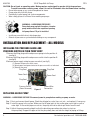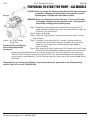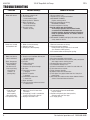
1
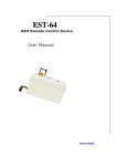
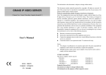
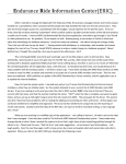
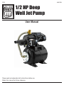
FTRY
8353799
1/2 HP Deep
Well Jet Pump
User Manual
Please read and understand all instructions before use.
Retain this manual for future reference.
FTRY
8353799
1/2 HP Deep
Well Jet Pump
SPECIFICATIONS
Power
120V / 60Hz
HP
1/2 HP
Max flow rate
13.5 GPM
Max. Head
66 PSI
Power cable
3C*SJTW 16 AWG*1.6m
Max. water temperature
35° C
IMPORTANT SAFETY PRECAUTIONS
WARNING! Read and understand all instructions before using this tool. Failure to follow all instructions may result
in electric shock, fire and/or personal injury. Keep this manual for the safety warnings and precautions, operating,
inspection and maintenance instructions. When using this tool, basic precautions should always be followed to
reduce the risk of personal injury and/or damage to the equipment. Note that when this manual refers to a part
number, it refers to the parts list included.
SPECIFIC SAFETY PRECAUTIONS
WARNING! Hazardous voltage can shock, burn or
cause death. Ground pump before connecting to
power supply. Disconnect power before working
on pump, motor or tank.
Wire motor for correct voltage. See “Electrical” section of this manual and motor nameplate.
• Ground motor before connecting to power supply.
• Meet National Electrical Code, and local codes for all wiring.
• Follow wiring instructions in this manual when connecting motor to power lines.
WARNING! Capacitor voltage may be hazardous. To discharge motor capacitor, hold insulated handle
screwdriver BY THE HANDLE and short capacitor terminals together. Do not touch metal screwdriver blade or
capacitor terminals. If in doubt, consult a qualified electrician.
For technical questions call: 1-800-665-8685
3
8353799
1/2 HP Deep Well Jet Pump
FTRY
CAUTION: Do not touch an operating motor. Modern motors are designed to operate at high temperatures.
To avoid burns when servicing pump, allow it to cool for 20 minutes after shut-down before handling.
• Do not allow pump or any system component to freeze.
• Pump water only with this pump.
• Periodically inspect pump and system components.
• Wear safety glasses at all times when working on pumps.
WARNING – HAZARDOUS PRESSURE!
Pump body may explode if used as a booster
pump unless relief valve capable of passing
full pump flow at 75 psi is installed.
• Install pressure relief valve in discharge pipe.
• Release all pressure on system before working on any component.
INSTALLATION AND REPLACEMENT – ALL MODELS
INSTALLING THE PRESSURE GAUGE AND
PRESSURE SWITCH IN THEN PUMP BODY
1.Remove the filling plug and thread pressure gauge into the position A.
(see fig A)
2.Remove the filling plug and thread pressure switch into the position B.
(see fig B)
3.Connect power supply wiring to pressure switch (see fig C)
(1) Remove the pressure switch cover.
(2) Attach power and ground wires to the pressure switch as indicated.
(3) Reinstall the cover.
Figure A
Plug Cord
Plug Cord
Power Cord
Power Cord
Plug Cord
Figure B
Pressure Switch
(Cover Removed)
Figure C
Ground Wire
Connection
REPLACING AN OLD PUMP
WARNING – HAZARDOUS VOLTAGE! Disconnect power to pump before working on pump or motor.
Step 1. Drain and remove the old pump. Check the old pipe for scale, lime, rust, etc., and replace it if necessary.
Step 2. Install the pump in the system. Make sure that all pipe joints in the suction pipe are air tight as well as
water tight. If the suction pipe can suck air, the pump will not be able to pull water from the well.
Step 3. Adjust the pump mounting height so that the plumbing connections do not put a strain on
the pump body. Support the pipe so that the pump body does not take the weight of piping or fittings.
4
For technical questions call: 1-800-665-8685
FTRY
1/2 HP Deep Well Jet Pump
INSTALLATION—MODEL XDPM196A3
WARNING – HAZARDOUS VOLTAGE!
Disconnect power to pump before
working on pump or motor.
8353799
Figure 3: Drive and Suction Functions
Discharge
Suction (Larger Port)
Piping and Pressure Regulator
omitted from diagram for clarity
Step 1. Drain and remove the old pump. Check the old pipe
for scale, lime, rust, etc., and replace it if necessary. Drive
Step 2. Install the ejector kit. Follow the instructions provided (Smaller Port)
with the kit. Be sure to align the venturi with the top
hole on the front of the pump (see Figure 3).
Drive Pipe - sends water down the
NOTICE: Always replace the ejector when replacing the
well to drive water up through the
pump in a shallow well installation.
Suction Pipe to Pump Suction
Step 3. Install the pump and faucet in the system. Make sure
that all pipe joints in the suction pipe are air-tight as
Figure 4: Mount Ejector
well as water tight. If the suction pipe can suck air,
the pump will not be able to pull water from the well.
Step 4. Adjust the pump mounting height so that the plumbing
connections do not put a strain on the pump body.
Support the pipe so that the pump body does not take
the weight of piping or fittings.
Step 5. Run piping from elbow to the household piping. The
discharge piping must be at least as large as the elbow.
You have just completed the well plumbing for your new jet pump system.
INSTALLATION— MODEL XDPM196A3
Step 1. Remove the control valve from the pump body.
Replace it with a 1” NPT close nipple,
a 1”x1” NPT elbow, and (see Figure 1).
Step 2. Install the ejector kit. Follow the instructions
provided with the kit. Align the venturi with the
top hole on the front of the pump (see Figure 6).
CASED WELL INSTALLATION,
2" OR LARGER CASING (FIGURE 5)
Figure 5: Cased Well Installation
NOT TO SCALE
Suction pipe
from well
Step 3. Mount the pump as close to the well as possible.
Connect the pipe from the well to the pump suction
At least 10 ft
port, using the fewest possible fittings – especially
elbows – as fittings increase friction in the pipe.
Step 4. Assemble the foot valve, strainer, and well pipe
5-10 ft
(see Figure 5). Make sure that the foot valve
works freely.
Step 5. Lower the pipe into the well until the strainer is 5 feet
above the bottom of the well. It should also be at least
10 feet below the well’s water level while the pump is
running in order to prevent the pump from sucking air. Install a sanitary well seal.
For technical questions call: 1-800-665-8685
Sanitary well seal
Well Casing
Foot Valve
Strainer
5
8353799
NOT TO SCALE
1/2 HP Deep Well Jet Pump
FTRY
DRIVEN POINT INSTALLATION (FIGURE 6)
Suction pipe
from well
Check Valve
Drive Coupling
Drive Point
Figure 6: Driven Point Installation
Step 3. Drive the well, using “drive couplings” and a “drive cap”. “Drive
fittings” are threaded all the way through and allow the pipe ends
to butt against each other so that the driving force of the maul is
carried by the pipe and not by the threads. The ordinary fittings
found in hardware stores are not threaded all the way through
the fitting and can collapse under impact. “Drive fittings” are also
smoother than standard plumbing fittings, making ground
penetration easier.
Step 4. Mount the pump as close to the wall as possible.
Step 5. If one well point does not supply enough water, consider
connecting two or three well points to one suction pipe.
ALL PUMP INSTALLATIONS
Step 6. Install elbows, and suction pipe to the pump (see Figures 5
and 6). Connect the pipe from the well to the pump suction port,
using the fewest possible fittings – especially elbows – as fittings
increase friction in the pipe.
•
•
•
The suction pipe should be at least as large as the suction port on
the pump (include a check valve – see Figures 5 and 6).
Support the pipe so that there are no dips or sags in the pipe, so it
doesn’t strain the pump body, and so that it slopes slightly upward
from the well to the pump (high spots can cause air pockets which
can air lock the pump).
Seal the suction pipe joints with Teflon tape or pipe joint
compound approved for use on PVC. Joints must be air and water
tight. If the suction pipe can suck air, the pump cannot pull water
from the well.
Step 7. Run piping from the elbow to the house- hold piping. The
discharge piping must be at least as large as the elbow.
You have just completed the piping for your new jet pump system!
ELECTRICAL—ALL MODELS
CONNECTION PROCEDURE:
Step 1. Connect the ground wire first as shown in Page 4. The ground wire must be a solid copper wire at least
as large as the power supply wires.
Step 2. There must be a solid metal connection between the pressure switch and the motor for motor grounding
protection. If the pressure switch is not connected to the motor, connect the ground screw in the switch
to the ground screw under the motor end cover. Use a solid copper wire at least as large as the power
supply wires.
Step 3. Connect the ground wire to a
a) grounded lead in a service panel
b) a metal underground water pipe
c) metal well casing at least ten feet (3M) long
d) to a ground electrode provided by the power company or the hydro authority.
Step 4. Connect the power supply wires to the pressure switch as shown in Page 4.
You have just completed the wiring for your pump. Please go to startup preparations on page 7.
6
For technical questions call: 1-800-665-8685
FTRY
1/2 HP Deep Well Jet Pump
8353799
PREPARING TO START THE PUMP – ALL MODELS
CAUTION: Never run a pump dry. Running pump without water may cause pump
to overheat, damaging seal and possibly causing burns to persons
handling pump. Fill pump with water before starting.
WARNING! Never run pump against closed discharge. To do so can boil water
inside pump, causing hazardous pressure in unit, risk of explosion
and possibly scalding persons handling pump.
Step 1. Remove the priming plug from the pump and fill the pump, fill all
piping between the pump and the well, and make sure that all pip- ing
in the well is full (see Figure 7).
Step 2. Replace all fill plugs.
Step 3. Power on! Start the pump. The pump should pump water in two or
three minutes.
Step 4. If you don’t have water after 2 or 3 minutes, stop the pump and
Figure 7: Fill Pump Through
remove the fill plugs. Refill the pump and piping. You may have to
Filling Plug
repeat this two or three times in order to get all the trapped air
Remove fill plug and fill pump
out of the piping.
and suction piping through
Step 5. After the pump has built up pressure in the system and shut off, check
priming tee
the pressure switch operation by opening a faucet or two and running
enough water out to bleed off pressure until the pump starts. The pump should start when pressure
drops to 20 PSI and stop when pressure reaches 40 PSI. Run the pump through one or two complete
cycles to verify correct operation. This will also help clean the system of dirt and scale dislodged during
installation.
Congratulations on a successful installation. If you were unsuccessful, please refer to the Troubleshooting
section (Pages 8& 9) or call 1-800-665-8685.
For technical questions call: 1-800-665-8685
7
8353799
1/2 HP Deep Well Jet Pump
FTRY
TROUBLESHOOTING
SYMPTOM
CORRECTIVE ACTION
Motor will not run
1. Disconnect switch is off.
2. Fuse is blown or
circuit breaker tripped.
3. Starting switch is defective
4. Wires at motor are
loose, disconnected,
or wired incorrectly.
5. Pressure switch
contacts are dirty
1. Be sure switch is on.
2. Replace fuse or reset circuit breaker.
3. DISCONNECT POWER;
Replace starting switch.
4. Refer to instructions on wiring,
DISCONNECT POWER.
5. Check and tighten all wiring.
Capacitor voltage may be hazardous.
To discharge capacitor, hold insulated handle
screwdriver BY THE HANDLE and short capacitor
terminals together. Do not touch metal screwdriver
blade or capacitor terminals. If in doubt, consult a
qualified electrician.
6. DISCONNECT POWER and lightly file contacts with fine
emery board or nail file.
Motor runs hot and
overload kicks off
1. Motor is wired incorrectly
2. Voltage is too low
3. Pump cycles too frequently
1. Refer to instructions on wiring.
2. Check with power company.
Install heavier wiring if wire size is too small
(See Electrical / Wiring Chart).
3. See section below on too frequent cycling.
Motor runs but no
water is delivered
1. Pump in new installation did not pick
up prime through:
a) Improper priming
b) Air leaks
c) Leaking foot valve
or check valve
2. Pump has lost prime through:
a) Air leaks
b) Foot valve or strainer
is plugged
c) Ejector or impeller
is plugged
d) Check valve or foot valve
is stuck shut
e) Pipes are frozen
f) Foot valve and/or strainer are buried
in sand or mud
1. In new installation:
a) Re-prime according to instructions.
b) Check all connections on suction line, AVC, and ejector
with soapy water or shaving cream.
c) Replace foot valve or check valve.
2. In installation already in use:
a) Check all connections on suction line and shaft seal.
b) Clean foot valve or strainer.
c) Clean ejector or impeller.
d) Replace check valve or foot valve.
e) Thaw pipes. Bury pipes below frost line. Heat pit or
pump house.
f) Raise foot valve and/or strainer above bottom of water
source. Clean foot valve and strainer.
1. Water level in well is lower than
estimated
2. Steel piping (if used) is corroded or
limed, causing excess friction
3. Piping is too small in size
1. A new nozzle and venturi combination
may be needed.
2. Replace with plastic pipe where possible,
otherwise with new steel pipe.
3. Use larger piping.
(Note: Stop pump;
then check prime
before looking
for other causes.
Unscrew priming
plug and see
if water is in
priming hole).
Pump does not
deliver water
to full capacity
(Also check point
1c of previous row)
8
POSSIBLE CAUSE(S)
For technical questions call: 1-800-665-8685
FTRY
1/2 HP Deep Well Jet Pump
8353799
SYMPTOM
POSSIBLE CAUSE(S)
CORRECTIVE ACTION
Pump delivers
water but does
not shut off
or pump cycles
too frequently
1. Pressure switch is out of adjustment
or contacts are welded together
2. Faucets have been left open
3. Venturi, nozzle or impeller is clogged
4. Standard pressure tank is
waterlogged and has no air cushion
5. Pipes leak
6. Foot valves leak
7. Pressure switch is out of adjustment
8. Air charge too low in
pre-charged tank
1. DISCONNECT POWER;
adjust or replace pressure switch.
2. Close faucets.
3. Clean venturi, nozzle or impeller.
4. Drain tank to air volume control port. Check AVC for
defects. Check all connections for air leaks.
5. Check connections.
6. Replace foot valve.
7. Adjust or replace pressure switch.
8. DISCONNECT POWER and open faucets until all
pressure is relieved. Using tire pressure gauge,
check air pressure in tank at valve stem located
on the tank. If less than pressure switch cut-in setting
(20-40 PSI), pump air into tank from outside source
until air pressure is 2 PSI less than cut-in setting of
switch. Check air valve for leaks (use soapy solution)
and replace core if necessary.
1. Pump is picking up prime
2. Leak in suction side of pump
3. Well is gaseous
4. Intermittent over-pumping of well.
(Water drawn down below foot
valve.)
1. When pump has picked up prime, it should pump solid
water with no air.
2. Suction pipe is sucking air. Check joints for leaks with
soapy water.
3. Consult factory about installing a sleeve in the well.
4. Lower foot valve if possible, otherwise restrict
pump discharge.
Air spurts
from faucets
For technical questions call: 1-800-665-8685
9
8353799
1/2 HP Deep Well Jet Pump
FTRY
REPAIR PARTS
Part no.
Description
Qty
2
Nozzle
1
3
Adjutage
1
4
Filling plug
2
5
Pump body
1
6
Three-ways
1
7
Diffuser
1
8
Motor stator
1
9
Terminal box
1
10
Capacitor
1
11
Terminal cover
1
12
Terminal
1
13
End plate
1
14
Screw
3
15
Fan
1
16
Fan cover
1
17
Ball bearing
1
18
Rotor
1
19
Pump support
1
20
Impeller
1
21
Pressure guage
1
22
Tank
1
23
Pressure switch
1
24
Flexible Tube
1
1
10
Ejector
1
For technical questions call: 1-800-665-8685