1
New WinRoddier Version 3 User Manual
Utilizing the latest 64-bit-compatible processing software and completely revamped processing methods
Wade Van Arsdale
Manual Revision 1.4, Last revision, 12/11/2013
© 2013 Wade Van Arsdale
1
Table of Contents:
Preface ----------------------------------------------------------------------------------------- Page 2
Chapter 1: Equipment Selection and Considerations ------------------------------- Page 4
Chapter 2: Telescope and Camera Setup ---------------------------------------------- Page 8
Chapter 3: Using WRCALC to Calculate the Proper On-Screen Star Size----- Page 11
Chapter 4: Image Capture ---------------------------------------------------------------- Page 13
Chapter 5: Processing the Image Stack With Auto-Stakkert 2 Software ------- Page 17
Chapter 6: Prep of Master .Fits Frames with the WRFITS Software ----------- Page 24
Chapter 7: Analysis of Processed Master Files in the WinRoddier Software -- Page 28
Chapter 8: Other Options and Software for Further Processing Your
WinRoddier Results ------------------------------------------------------------------------- Page 41
Appendix 1: Links to Software ----------------------------------------------------------- Page 43
Appendix 2: Math Calculations for Correct Amount of Defocus ----------------- Page 45
Appendix 3: Credits ------------------------------------------------------------------------ Page 48
Preface
The WinRoddier optical analysis software is a very powerful and accurate tool that allows amateur astronomers a
viable way to assess the optical quality of their telescope without the need to purchase an expensive interferometer or
learn how to use one. A relatively inexpensive and easy-to-use astronomical video camera is used to capture the star
images for analysis with the WinRoddier software.
The earlier WinRoddier methods involved traditional thermoelectrically-cooled mono CCD cameras. Even DSLR
cameras can be used as well, by extracting the green frames from the full-color frames and using these specific
frames to analyze with WinRoddier. Both of these use longer exposures that are long enough to overcome the effects
of seeing turbulence, but not so long that mount tracking becomes a problem for star-trailing. These types of cameras
remain valid for WinRoddier today just as much as they were earlier.
But for the purposes of this manual, we will focus on video CCD cameras to capture the WinRoddier star data.
Modern, fast frame-rate video cams offer the following advantages over traditional CCD cameras and DSLR's:
1) The ability to collect very large stacks of data quickly. Large stacks of 1000-2000 frames allow you to get very
"clean" data that has less random seeing turbulence and other noise effects. Problematic mount tracking, if not too
severe, can be overcome easier with video cameras. All these factors allow for a very accurate analysis by the
WinRoddier software.
2) Relatively low cost of good quality, high-speed video cameras compared to the cost of traditional cooled CCD
cameras and some DSLR cameras.
3) Very fast frame rates allow you to "freeze the seeing" by helping to reduce the effects of atmospheric turbulence
on the wavefront quality.
You are encouraged before beginning here to first review the excellent original WinRoddier manual titled "A
Cookbook for Roddier Testing of Telescopes" by John Biretta of the Yahoo Roddier Test Group:
http://groups.yahoo.com/neo/groups/roddier/conversations/topics
2
(You will need to join the Yahoo Roddier Test Group (free) to obtain access to the original Cookbook and other
instructional guides there that will be mentioned later in this manual).
Also, it will be very helpful to read thoroughly the original WinRoddier research paper by Claude Roddier and
Francois Roddier that can be downloaded from this link:
http://www.soft.belastro.net/files/tmp/Wavefront_reconstruction_from_defocused_images_and_the_testing_of_ground-based_optical_telescopes.pdf
The Roddier original research paper has some very good explanations of the optical theory and methods behind
WinRoddier optical testing of telescopes.
The goal of this new manual is to modernize and simplify the image prep process prior to opening the test images
inside the WinRoddier software, and do all that at a lower cost than the software that was used earlier. In fact, this
new method is currently FREE for all apps that are used from start to finish with the exception of the "CrossHare"
app which is very low cost (see Appendix 1 at the end of this manual for web links to all the software).
Over the past few years, some of the original prep software has become harder to get, or harder to use in today's 64bit versions of Microsoft Windows. The new method uses the latest software, is much easier and faster to prep the
image files with, and will work on 64-bit Windows operating systems and modern multi-core processors used in the
latest computers.
3
Chapter 1: Equipment Selection Considerations
With the rapid advancement of astronomical video camera technology, some very nice ones are available nowadays
that make it easier to do WinRoddier analysis, and more accurately as well. The principle behind using a video
camera instead of a traditional still-frame CCD camera (as was done in the original research several years ago) is to
take large data stacks of hundreds or even thousands of images. Then by combining and processing these large
stacks, the software does a better job of eliminating the random atmospheric "noise" of the images. With the frame
speed of modern video cameras today, it is typical to take a stack of 1000-2000 images for the Intrafocal stack, and
the same amount for the Extrafocal stack! And all of this can be done in just a minute or less for each stack with a
modern video camera and computer!
Camera Considerations:
First and foremost, you want a video camera that has a very fast frame rate per second. This is crucial to "freeze the
seeing". As the frame rate increases, the warping of each individual frame's star test image lessens, which gives a
much less skewed test pattern. Fast frame rates decrease the detrimental effects of atmospheric and internal air
turbulence on the wavefront quality of the telescope. So this allows you to get a more accurate result with
WinRoddier much closer to what an interferometer in a controlled lab bench-test environment can do. Typical
*minimum* frame rates to go for when looking for a camera to use are currently around 30-60 fps at a frame size of
640 x 480 pixels, or faster if you can find it.
The next camera consideration is to assess the size of the camera's individual pixels and camera chip dimensions, and
how this combines with the telescope's focal length to affect the size of the star image on the camera's chip. You
want a chip that is large enough to get the defocused image to stay on the chip during atmospheric turbulence or
mount tracking slight errors. A larger CCD chip also allows you to find and put the target star into the camera's field
of view (FOV) easier with less "hunting" of the star on-screen. With most amateur telescopes that means a camera
that will produce an unbinned frame size of at least 800 x 600 pixels.
Smaller pixels cause larger defocused star images than larger pixels for the same amount of defocus. Likewise,
longer focal lengths for your telescope also translate to larger defocused star images. So you can see from this that if
you have a very long focal length instrument, you may not necessarily want the video camera with the tiniest pixels
you can find.
Learning and using the defocus math helps greatly in pre-planning for which camera will best serve a specific
telescope for WinRoddier analysis. See Appendix 2 of this manual for the formulae and examples to work through to
learn the math surrounding defocus and how to calculate it properly. Your target amount of defocus for best results is
around 15-20 waves *minimum*. Conversely, there is an outer limit to defocus with WinRoddier that causes the
image to lose its resolution of the optical aberrations. The result is that WR will not measure the optics as accurately
at this point. This varies depending on the telescope, but you can be pretty much assured that 15-20 waves of defocus
out to around 25-30 waves will be a good, effective range to stay within for your defocus with WinRoddier.
Atmospheric Turbulence and its effects on WinRoddier:
This is the one variable that we don't have much control over. When there is a lot of atmospheric turbulence present
(lots of star "swim" in the image display on your pc screen), it's best to wait for a better night with better seeing
conditions. You may be wondering "what is good seeing"? Generally, you can get accurate WinRoddier results in
atmospheric seeing of around 1.5-2.0 arc-seconds seeing or better. But if seeing has worsened to 2.5 arc-seconds or
worse, you should wait for a steadier atmosphere to test in.
There are several software apps available that can measure the seeing for you. The free MetaGuide camera app
mentioned in various parts of this manual is an example of an app that can measure the seeing conditions for you.
4
To get you started on getting familiar with some of the video camera brands and models out there, below is a list of
good ones to consider if you are shopping for a good camera to do WinRoddier testing with. This is by no means a
complete list....just a sample list to get you started. There are many other good ones out there too.
Currently available examples of suitable video cameras for WinRoddier testing:
QHY5L-II: http://qhyccd.com/en/left/page3/qhy5-ii-series/
ZWOptical ASI-120MM: http://zwoptical.com/Eng/Cameras/ASI120/index.asp
Point Grey Flea-3: http://ww2.ptgrey.com/USB3/Flea3
The Imaging Source DMK series video cameras: http://www.astronomycameras.com/products/usb/
Lumenera Skynyx Video Cameras: http://www.lumenera.com/products/astro-cameras/
Color vs. Mono Video Cameras:
There is generally nothing much to be gained from using a color video camera for WinRoddier analysis. So in most
cases, you will want to go with a mono camera, although a color camera will work, especially if you already own one.
While you can shoot through color filters with your mono camera and analyze the different color bandwidths of your
telescope to see how well corrected the optics of your telescope are in the different bandwidths, generally just
shooting on the Luminance broadband wavelength is fine for our purposes when using WinRoddier. If you do use a
color video camera or DSLR, usually you will want to extract the Green frames to work with the most often with
WinRoddier since they are at the midpoint of the visual bandwidth which is the most important part of the light
spectrum for visual work with your telescope.
Be sure, especially if shooting with a color camera to use a good quality IR/UV cutoff filter in front of the camera
chip to reduce optical spherical aberration distortions from the extended camera bandwidth sensitivity in the far-red
and far-blue bandwidths that might skew the WinRoddier results.
Camera chip size considerations:
With today's modern video cams, larger chips are becoming the norm. A larger 1/3 to 1/2 inch chip makes it easier to
find the star in the camera's field of view. A larger chip also makes it easier to keep the defocused star image on the
chip while the telescope is tracking. There are trade-offs on chip size however. Generally, the larger the frame size,
the slower the frame rates will be. One trick that can be used with your capture software is to use "Region of
Interest". ROI uses a central portion of the chip's pixels only, at a cost of frame size and allows you to speed up the
frame rates, sometimes dramatically. As long as you can still keep the defocused star image in the camera's FOV
with ROI and keep the image away from the FOV edges by around 30-50 pixels, this can be used to speed up the
frames per second (fps) and freeze the seeing better to get better quality star images.
A good game plan is to get a camera that has a pretty large maximum frame size of 1024, 1280, or 1600 horizontal
pixels for easier target placement on the CCD chip, but use it in ROI mode at a frame size of 640x480 pixels for
longer focal length scopes, or 320x240 pixel ROI for shorter focal length telescopes. Many cameras and apps will
allow you to combine ROI with 2x2 binning. This is a big help with longer focal-length telescopes or cameras with
the smallest pixels of 2.5 microns per pixel or smaller.
Telescope Mechanical Considerations:
In order to get an accurate WinRoddier analysis of your telescope, you also need to have a well-collimated telescope
that is in good optical alignment all the way from the tip-tilt of the secondary mirror to the back end and focuser
alignment. If the telescope is poorly collimated or has a misaligned, off-center optical axis, or tilted focuser on the
back end, this will degrade your WinRoddier results and the wavefront performance of your telescope.
For high-precision collimation of SCT's and other compound mirror telescopes, the MetaGuide software app by
Frank "freestar8n" of AstroGeeks.com and the Yahoo MetaGuide User Group is a very useful and handy tool. The
software is free currently, and can be downloaded at this link:
http://astrogeeks.com/Bliss/MetaGuide/index.html
5
MetaGuide Discussion Group: http://ca.groups.yahoo.com/group/AstroGeeks/
MetaGuide gives you an effective way to visualize the collimation of the telescope on your pc screen while you
collimate it. Using a very fast video camera to produce a star pattern inside MetaGuide is a much easier and more
accurate way to visualize a defocused star pattern to collimate with than trying to watch a star's diffraction rings while
it's swimming all over the field of view in your eyepiece. MetaGuide also utilizes some helper tools for at-focus
collimation that are far beyond just looking at a star test pattern on-screen. It truly is a tool that allows you when
done in good seeing conditions to "hyper-collimate" your telescope to a level that is as close to perfect as can be done
without using a bench-test with an interferometer.
For other aspects of optical alignment of SCT's such as decentering of the secondary-primary mirror axis, focuser tilt,
off-centered focuser, etc...., I use the Hotech Advanced CT Laser Collimator to square up the optical axis from front
to back of the scope. It is beyond the scope of this manual to go into those processes here, but you can go to this link
for more info on David Ho's excellent collimator hardware: http://www.hotechusa.com/Default.asp
Telescope Design and Focal Length Considerations:
Typically, the type of telescope you would be most interested in analyzing with WinRoddier would be one that is
going to be used for high-resolution work such as planetary visual or CCD work, double-star observing, globular
clusters, planetary nebulae, etc.... These types of uses put the most demands on your telescope and require that the
scope be well-aligned optically and have good optical quality. Telescopes used primarily at shorter focal ratios for
wide-field, deep-sky visual or photographic work do not have to be quite as optically precise, especially when you are
stacking quantities of deep-sky image frames during imaging (although they do need to be well-collimated for best
results no matter how you're using them).
As you can see from the above discussion, if you have a telescope with a really long focal length, and you combine
this with a camera that has a very tiny pixel micron size, you may wind up with a star image that is way too large to
fit on a smaller CCD chip that can only produce image frame sizes of 640 x 480 or smaller. So keep this in mind and
shop wisely when looking for a good video camera for WinRoddier use.
Generally, with very long focal-length instruments such as f/10 to f/11 SCT's or f/12-f/15 Maksutovs, you will want a
little bit larger pixel micron sizes in the 4.4u to 7.4u ranges, not smaller ones. But with the typical focal lengths of
f/6 to f/8 doublet and triplet refractors along with shorter Newtonians, you'll want to go as small as possible on pixel
sizes. There are currently cameras that have pixel sizes all the way down to 1.25-2.5 microns in size that work great
for analyzing refractors and Newtonians of moderate to short focal ratios and will allow you to get the amount of
defocusing that WinRoddier needs to do accurate optical measurements.
Note, we are talking about two different things here: pixel size vs. chip size. The smaller the pixels, the larger the
star image that is produced. But the larger the chip size, the easier it is to put the image into the camera's FOV and
keep it there.
A note about binning the camera 2x2 to reduce star diameters to acceptable levels:
You may be wondering, "why would we want to hurt the resolution of the system by binning the camera 2x2 to
reduce very large images"? (Binning is often used for WinRoddier with very long focal-length scopes and/or tiny
camera pixel sizes).
WinRoddier is able to calculate the optical aberrations for a binned image once you input the bin parameter that was
used into WinRoddier's Telescope Parameters/Instrument Used screen. WinRoddier does not lose any accuracy in its
calculations when you have to bin your camera as long as you let WinRoddier know that you did indeed bin the
camera. WinRoddier does not have to use highest possible image scale resolution to work well. So it's a little
different in its approach vs. high-res. planetary video capture for example.
6
I have not evaluated 3x3 binning, but I suspect you won't find a commercially available amateur telescope that would
require that much binning.
Shoot in 16-bit or 8-bit mode? With the large frame stacks of our method, 8-bit capture mode is sufficient for the
data collection. There isn't anything to be gained from 16-bit mode with WinRoddier image data.
How large for a defocused star image on-screen?
I've found through many dozens of test cycles that WinRoddier's optimum "zone" to work in is a defocused star
diameter of around 100-150 pixels at a minimum of 15-20 waves of defocus. A maximum total frame size of 640 x
480 pixels, while not at the limits of WinRoddier's capabilities, is a good upper limit to keep in mind so you can keep
your computer's image processing speeds up in WinRoddier, especially on slower computers.
Also, keep in mind that you can use ROI and binning to reduce total frame sizes, and ROI specifically as a way to
speed up the camera's frame rates (more on that below) and the computer's processing speed. So keep these two
limits in mind when planning ahead for your shooting. When you amplify the image size too much, you get to a
point where the aberrations become lost in the background noise of the image which causes inaccurate WinRoddier
results.
Let's say for example, you are using a camera set to a frame size of 800 x 600 pixels, and the star image when
properly defocused 15-20 waves gives you a star diameter of 200 pixels. You can see from the above
recommendations that both specs are too far out of range for best results inside WinRoddier. So the easy solution
there is to bin the camera 2x2. With most modern video cameras that combine pixels when they are binned, this will
give you a star diameter of 100 pixels and a frame size of 400x300 pixels. Both parameters are "in the zone" for good
WinRoddier analysis.
But now let's say you have a telescope that when defocused the proper amount gives you a star diameter of just about
a perfect 120 pixels, but the frame size of the camera is 640 x 480 and has very slow frame rates which increases
atmospheric turbulence effects on the data. You can see from this that if you bin the camera 2x2 to reduce the total
frame size down to 320x240 pixels to get within WinRoddier's optimal limits, now your star diameter will be too
small for best results in WinRoddier (60 pixel star diameter after binning). The answer is to get a camera and use
capture software that both support "Region of Interest" (ROI). ROI allows you to decrease your overall frame size to
within the optimal zone in WinRoddier, but still keep your test-star diameter the same. So if you have a star diameter
you are happy with, you can keep it by using ROI when needed instead of binning 2x2. ROI just uses a central-most
portion of the camera chip that you define for it to use. ROI does not bin or combine pixels together in any way with
most video cameras. Remember when you use ROI to keep the edges of the defocused star image at least 30-50
pixels away from the edge of the frame. Allow good headroom on this in case you have some atmospheric turbulence
that makes the star image dance around, or your mount tracking is drifting a little bit during the shoot.
Another reason to bin is to brighten the star to acceptable levels. In many video cameras (but not all), binning
combines pixels just like in a traditional CCD camera. So a larger effective combined pixel captures more photons
which brightens the star image on-screen. This is desirable because it lets you decrease your camera's Gain and
Exposure time settings which will decrease camera dark-current noise to give you a little bit cleaner data for
WinRoddier to analyze. Remember from our earlier discussion above, binning (which decreases overall resolution of
the system) does not hurt the accuracy of the WinRoddier results.
Note that when we recommend a maximum target star diameter of 100-150 pixels, WinRoddier's calculation math
doesn't care *how* you get your star diameter into this optimal range or whether or not you bin or use ROI, just as
long as you have a sufficient amount of defocus of at least 15-20 waves.
7
Chapter 2: Telescope and Camera Setup
Initial Camera and Telescope Setup:
The primary potential weakness of the WinRoddier method of analysis is the presence of jet-stream atmospheric
turbulence since the test images are typically captured outdoors on a live star in the sky. The fact that you are in an
outdoor environment can introduce many factors that will destabilize the wavefront quality of the star images that you
are measuring with the WinRoddier software. That's not to say you can't capture images for WR in average to aboveaverage seeing, but avoid capturing data when the seeing is worse than about 2.5 arc-seconds FWHM.
Also, a telescope that is not in proper thermal equilibrium with the ambient outdoor temp will often have internal air
thermals inside the telescope tube itself that will badly degrade the wavefront quality and give artificially worsened
test results vs. what the telescope really is in terms of optical quality. This is probably the primary way that most new
WinRoddier users get bad results. Internal OTA thermals and non-equalized glass must be addressed before
collecting WinRoddier data or you will get inaccurate results.
Solving these factors as much as you can possibly do will greatly increase the accuracy of the WinRoddier optical
analysis. The following is a list of environmental destabilizing factors to the test, and suggestions on how to solve
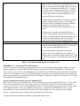
them:
Problem
Ground thermals: present in many locations, particularly
soon after sundown as the ground surface cools.
How to Fix
Do not use artificial stars to test with when ground
thermals are present. Instead, image a live star near
zenith in the sky to escape as much of the ground
thermals as possible. Wait until well after sundown to
decrease ground thermals.
Do not set your telescope up on paved or rocky surfaces
as this traps more heat and can worsen ground thermals.
Try to set up on grass or other cool surface that do not
radiate heat for long after sundown. Likewise, stay away
from nearby rooftops for the same reasons.
Atmospheric dispersion: present on live stars at low sky
altitudes. Can cause coma and astigmatism effects and
on the star test images. This is caused by shooting
through more of the atmospheric layer and the refractive
effects of the atmosphere. The lower the star altitude, the
worse these effects get. Particulate matter suspended in
the air also contributes to the test image quality being
degraded on lower-altitude stars.
As mentioned above, image only on stars that are near
the zenith. If seeing transparency is excellent and
overhead atmospheric turbulence is low, you can
typically image on stars down to about 60-70 degrees sky
altitude without much degradation of wavefront quality.
8
Internal telescope tube/glass thermals and glass boundary
layers
Make sure telescope glass has been allowed to cool a
sufficient amount of time before capturing the test star
images. Use internal fans if possible such as the Lymax
Cat Cooler for traditional open-baffle SCT's. You can
also use the Lymax in larger refractors over 5 inches if
needed, but be very careful when inserting the cooler in
the rear of the refractor so you don't knock loose the
internal baffle rings of the telescope.
For newer-design closed-baffle SCT's like the Celestron
EdgeHD, consider using the Starizona Cool-Edge or
Deep Space Products TempEst fan systems to help the
telescope tube walls and its glass reach better
equilibrium, and maintain it better throughout the test
session.
With larger tubes, consider ProtoStar felt flocking
internally, also combined with internal fans to prevent
recurrence of internal thermals and glass boundary layers
from the tube walls cooling too fast vs. the glass on
nights where the ambient temp is dropping rapidly.
Presence of jet stream overhead
This is the one thing you can't control. If the star image
is warping and swimming badly on-screen, your best bet
is to just give up for that night and not test.
There are some good Jet Stream Forecaster maps
available on the web at Intellicast.com, Weather.com,
Wunderground.com and other online weather sites. If the
jet stream is going to be over your location, don't test that
night.
Table 1: Wavefront destabilizing factors and how to fix
IMPORTANT: A word about SCT's and focusers:
With SCT's that move the primary mirror to achieve focus (or even those that use the secondary mirror), you will
need an aftermarket Crayford or Rack & Pinion focuser to get accurate results with WinRoddier. With movingmirror systems, you want to set your at-focus position with the factory default focuser knob and with the aftermarket
focuser set at its midpoint of travel so you will have plenty of drawtube travel available each direction to achieve the
proper star diameters for your intrafocal and extrafocal images. It's important to not move the mirrors of SCT's while
shooting data for WinRoddier analysis.
Special Considerations with the Celestron EdgeHD SCT's:
Observe the Celestron recommendations for correct backfocus spacing when testing EdgeHD OTA's. For the 8 inch
OTA, the correct spacing to your camera chip from the top of the factory thread-on 2 inch visual back adapter is
133mm. For the 9.25, 11, and 14 inch EdgeHD's, the correct spacing from the larger thread-on factory 2 inch visual
back adapter is 146mm. Try to stay within these distances by +/- 10mm for best WinRoddier results. Optical
aberrations such as coma and spherical aberration will increase slightly if you don't stay close to the optimum
distance. Use thread-on spacers to achieve this optimum distance if necessary.
Celestron Links to their backfocus schematics for EdgeHD Optical Tubes:
9
http://www.celestron.com/c3/support3/index.php?_m=knowledgebase&_a=viewarticle&kbarticleid=2260&nav=0,24
7
10
Chapter 3: Using WRCALC to Calculate the Proper On-Screen Star Size
The "WRCALC" software utility by Glenn Jolly is very useful for pre-planning your WinRoddier data collection.
WRCALC is used to pre-determine the desired on-screen star diameter size for a given amount of waves of defocus.
Appendix 2 of this manual has all the math involved with making the star diameter and waves of defocus
calculations, but WRCALC does all this for you!! This is a huge time saver and removes any risk of making an error
when doing the calculations manually.
You can download the WRCALC utility from the Yahoo Roddier Test Group > Files > WinRoddier Ver. 3 folder
if you are a group member, or you can get it from this alternate download site:
http://www.compubuild.com/astro/download/WRCALC.zip
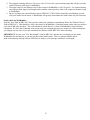
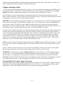
Here is what the WRCALC GUI screen looks like:
Figure 1: WRCALC GUI Screen
WRCALC Instructions:
1. Plug in all your telescope and camera parameters and the waves of defocus you want to use. Then, simply
click the "Calc" button in the WRCALC GUI screen.
2. After calculating, the "Messages" field of WRCALC will tell you what star diameter to use when you shoot
your data. Radius (diameter divided by 2) is also shown as a handy cross-check for WinRoddier. WR states
its star sizes in radius instead of diameter.
3. Consult the "New WinRoddier User Manual" for instructions on how to measure on-screen star diameters
accurately when shooting WinRoddier data.
11
4. The suggested starting defocus is 20 waves, out to 35 waves for a good working range that will give accurate
results with most telescopes in WinRoddier.
5. The target range for star diameter size for best results in WinRoddier is 100-150 pixels. Use camera binning
on telescopes with longer focal lengths and/or smaller camera pixels to achieve the target star diameter range
in WinRoddier.
6. Be sure to plug in the camera binning value in WRCALC's "Bin" field to match the actual binning you use
with your camera for the shoot, or WinRoddier will grossly miscalculate the Strehl values for your telescope.
Sanity check for WinRoddier:
Note the "mm" field in WRCALC after you have made your calculation (immediately below the "Defocus Waves"
field in WRCALC). This should be a fairly close match to WinRoddier's Calculator button results when you analyze
your data in WR after the shoot. This value should be within about 0.1-0.5mm of WinRoddier's mm of defocus
calculation. If it isn't, then something went wrong with your setup parameters or the actual size of the star diameter
you imaged was not close to your pre-calculated star diameter inside WRCALC before shooting.
IMPORTANT: be sure your "Test Wavelength" value in WRCALC matches the wavelength you use inside
WinRoddier for the analysis, or you may get inaccurate Strehl results. This is a common mistake that is
made when shooting through various color filters to analyze your telescope at different wavelengths.
12
Chapter 4: Image Capture
There are so many image capture apps available nowadays, we will just focus on the main points of how to setup
your capture app's most important features that WinRoddier needs in order to do accurate analysis. The FireCapture
app is currently one of the best ones out there, so we will use it for our example.
Generally, you want to use the following guidelines for your setup:
1) Make sure the Gamma setting is left at "flat" (no Gamma added or subtracted). Typically, this value will be "flat"
as the software's default setting. This value could be 0, 1, 5, 100, etc..., depending on which app you use, but check it
to make sure that your images remain linear or WinRoddier won't analyze them properly.
2) Defocused image size: you have two factors to consider here:
a) How much defocus is needed for WinRoddier to analyze accurately? Through well over one
hundred WinRoddier cycles, I've seen a clear trend that indicates 15-20 waves is about the
minimum amount of defocus you need for WinRoddier to analyze the image accurately.
IMPORTANT: Defocus is a critical factor in setting up correctly so WinRoddier will do accurate work. The #1
mistake that most people make when they use WinRoddier is to not defocus enough. This often leads to inaccurate
readings in WinRoddier. So to sum up, we know from the above discussion (and many test cycles of my own and
others) that we want 15-20 waves of defocus at a minimum, and a star diameter of 100-150 pixels.
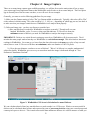
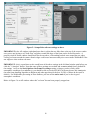
b) How does star diameter correlate to waves of defocus? "Waves" of defocus is a complex mathematical
subject but luckily, WinRoddier gives us a way to assess how much the image is defocused through its "Test
Parameters"/Instrument Used tab:
Figure 2: WinRoddier GUI Screen's Calculation for mm of Defocus
We can calculate ahead of time how much defocus we need to make it to 15-20 waves. What's even more useful is
defocus can be calculated ahead of time and expressed in terms of on-screen pixel size using your own telescope and
camera pixel specs to derive it. This is much more useful than millimeters because it is a direct measure of what you
13
are seeing on-screen in real time as you display the test star image through your camera and get ready to shoot the
stack. This makes it directly measurable using an on-screen adjustable software hash box or crosshair box that allows
you to adjust defocus and measure the image to get the size right before you capture the images. See Appendix 2 for
the math involved in this defocus calculation and examples for specific telescopes and cameras.
3) Make sure your star image does not get too close to the edges of the frame. This causes WinRoddier to give
skewed results and could even cause it to error-out completely and shut down. Leave a margin of at least 30-50
pixels or more between the edge of the defocused star and the edge of the frame. Adjust focus to achieve this. If
needed, also adjust ROI frame size for this as well. These tweaks will also help you keep the star edges from hitting
the frame edges during atmospheric turbulence which comes and goes during the shoot. It also gives you some
headroom in case the mount tracking is causing the star to drift a little during the shoot.
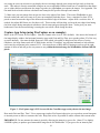
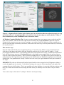
Capture App Setup (using FireCapture as an example):
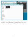
Below is the GUI screen for FireCapture. Note the Gamma value is set to "flat" (default). Also note at the bottom of
the image display window the horizontal intensity meter with Gain and Exp Time set to produce about 2/3 of the way
up on the intensity. Also note the high frame rate (FPS) which is desirable to help lessen the effects of seeing
turbulence, the large frame stack size of 2000 frames, and the "CrossHare" app software hashmark to help measure
and center the star pattern in the camera's FOV. Also note the use of ROI and 2x2 binning as tools to get the right
amount of defocus and still get the test-pattern to stay within the desired range for WinRoddier of about 100-150
pixels:
Figure 3: FireCapture App's GUI Screen with the CrossHare app overlayed onto the star image
How much Gain and Exp. Time? Use a capture app (such as FireCapture) that gives you a good on-screen histogram
or intensity meter as above to measure this with. Keep Gain as low as possible to reduce camera dark-current noise.
IMPORTANT: Do not saturate the camera's pixels by allowing the intensity to go too far. About 2/3 or slightly
LOWER is plenty to produce good measurable image stacks for WinRoddier. If you go too far on intensity and
14
saturate the camera pixels this will cause inaccurate analysis by WinRoddier. In your capture app, adjust the slider
bars to get the proper intensity on the level meter.
Trick to use for CrossHare app: I highly recommend the AstroGeeks "CrossHare" app for measuring the on-screen
star display size so you can get the amount of defocus right. A trick for this app is to first create a .jpg or other
"blank" image from inside Photoshop or your favorite other paint/draw app. In most of these apps you can set the
image size in pixels when you create it. So let's say you have calculated for your scope and camera that in order to
get 15 waves of defocus you will need an on-screen image size of 100 pixels (like the image above in Figure 2), you
can create a 100 x 100 pixel image in the paintshop app, then open the CrossHare app and position its hashmark grid
over the new blank image, adjust the hash size, then go to FireCapture and overlay the CrossHare hashmark box over
the live star display. If the blank size is too large for the CrossHare's hash mark range, just use the CrossHare
window itself as the hash guide and adjust the entire CrossHare window size as needed. The default setting for
CrossHare is "Always on Top", so you can easily keep track of it and use it while working in several apps at once.
Image Stack Size Recommendations:
Ground thermals and even internal OTA thermals can sometimes cause uneven field illumination defects on the
defocused star image that can affect the WinRoddier accuracy. These slow-rolling defects can take several seconds
to cycle through the image. The larger the aperture of the scope, the worse this effect can be, and the longer it can
take to cycle through. The way to combat this is to take longer total stack times of at least 1-2 minutes each for the
Intrafocal and Extrafocal stacks. Below is a table that summarizes the recommendations for aperture vs. stack length,
when taken in average to better conditions:
Aperture (mm)
60-100
100-200
200-300
>300
Capture Time (seconds)
30
45-60
60-100
100-240
Table 2: Capture Times vs. Telescope Aperture
NOTE: whatever final stack size you arrive at for your Intrafocal stack to meet the above recommendations, do the
same exact frame count for the Extrafocal stack as well. Remember these general principles: when in doubt, go to
more frames, not less. This is particularly true in average or marginal seeing. But when in good to very good seeing,
on scopes that are well-controlled and equalized thermally, a 1-2 minute video capture loop for each side of focus
should be sufficient even for larger scopes in the 11-14 inch aperture range, and will give accurate WR results. Note,
the number of frames you will get in a loop will depend on how fast your webcam is. When in doubt, take more
frames if you have a slower camera.
Other Seeing-Induced Anomalies:
In terms of frame counts/total stack times, clearly there is no penalty for longer. For smaller scopes as long as
enough frames are collected to provide the bit depth needed for a good analysis then 30 seconds seems reasonable.
The important thing is that the individual frames need to be short enough to freeze image movement.
Note: Certain seeing may be experienced where these total stack times, even when increased significantly, will not
improve the analysis. In fact good seeing does not guarantee accuracy. Conditions have been seen occasionally with
surprising levels of aberrations in otherwise very good seeing. The most common terms seen in these cases are
additional astigmatism and trefoil. In some of these cases, but not all, capturing a star as nearly overhead as possible
may help.
If a user does find unexpected aberration terms they should repeat the test on a different night. The environmental
15
conditions of the night should be recorded, including temperature and winds aloft as well as direction. If the user is
using a compound scope they should also document the back focus.
Capture the image stack:
1) After you've gotten everything setup as above, shoot a 1-2 minute long frame stack with the star INSIDE of focus
the prescribed amount. Then shoot a 2nd stack of identical frame count with the star OUTSIDE of focus the same
amount (star produces roughly the same display size as the other stack to within about 3-4 pixels.
DO NOT adjust your Gain or Exp settings at all when going from Intra to Extrafocal image stacks in the same
dataset. Don't touch them!!! This is critical to preserve the image accuracy of each stack with each other since WR is
comparing the two stacks as it processes the optical aberrations.
IMPORTANT: it is critical that you get the star diameter very close to the same size in both the Intra and Extrafocal
stacks, down to within about 3-4 pixels diameter margin of error. If you don't do this, it may cause WinRoddier to
give inaccurate results. WR does have some capability to adjust the star sizes when it processes the two master
images, but try to keep it as close as possible. Take some time when changing from Intra to Extrafocal stacks to use
the CrossHare app very carefully and get this part right. It will definitely help your results!!
2) Shoot 2-3 more Intra/Extrafocal stacks, each dataset with longer frame counts than the last (I like to go upward in
500-1000 frame increments depending on the speed of the camera) all using varying amounts of defocus and onscreen star diameters staying within the desired range of 100-150 pixels, a working outward to defocus values of 3035 waves (use the WRCALC utility to pre-calculate). Also note, on longer focal-length instruments you may be
constrained to 20-25 waves maximum, even with camera binning, or your image will get too large for good WR
results. Now you will have a good set of varying data to compare once you process all the stacks. I like to shoot
around three to four total datasets within a session, all of differing star sizes.
NOTE: it is OK to adjust Gain and Exp settings when you start a NEW dataset at a different star diameter. You will
have to do this to keep your star bright enough as you increase the amount of defocus to get larger patterns for each
new stack.
I prefer ".SER" file capture format for its ease of use in the Auto-Stakkert (AS) app (covered later in this manual).
But for AS processing, you can also shoot in other formats such as .bmp, .fit, .jpg, .tif, or .png.
TO REVIEW: remember your two goals: minimum defocus of at least 15-20 waves, and star diameter range of
100-150 pixels. Use a combination of focus adjustment, binning 2x2, and ROI (any one, two, or all three of those
tricks) to achieve your target goals for the proper data collection. I seem to get the most consistent results with
WinRoddier at about 100-120 pixels for the on-screen star diameter, but your results may vary depending on many of
the variables discussed earlier. A good working range for defocus is 20-35 waves for most telescopes.
A Word About Post-Capture Image Processing:
With WinRoddier, for best results, do not do anything to alter the image frames' native capture condition or linearity
of the images. Don't do any Histogram stretching at all (Levels, Curves, etc....), No Sharpening, and don't adjust
Brightness or Contrast. Basically don't touch them in any way after capturing the data stacks.
16
CHAPTER 5: Processing the Image Stacks with the Auto-Stakkert-2
Software App
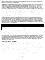
The Auto-Stakkert (AS) software allows you to process your main image stacks into a precision aligned and
combined master file for import into WinRoddier. Here are the steps to using AS:
Figure 4: Open the Intrafocal stack
17
Figure 5: Setup all the software settings as above.
IMPORTANT in the AP window (right-hand pane above), adjust the two slider bars at the top of the screen to make
sure you are not leaving a red "dead-zone" anywhere around the edges of the frame on the In and Out stacks. A
properly sized AP frame window should look like the one above, with nothing but dark zone around the star edges.
Leaving red zones around the camera frame's edges could cause inaccurate analysis or errors inside WinRoddier if the
star edges are close to these red zones.
IMPORTANT: this is a good time to take careful note of the above settings in the left-hand window pain before you
click the "1) Analyze" button. Note that some of these settings are tweaked and are not standard factory default for
the settings. As far as the Stack Options>On-Frame Percentage setting, as long as you have fairly stable
atmospheric conditions (low turbulence), you should be able to use the full 100% of the stack (note, this is not quite
the same frame handling algorithm as Registax and other apps that pick the best 10-20% of frames in the stack as
default). For WinRoddier processing in Auto-Stakkert, you can use the entire stack if you've shot in good
atmospheric conditions.
Below in Figure 5 is an AP window where this "red zone" has not been properly cropped out.
18
Figure 6: Alignment Points window (right window-pane) has not had the slider bars adjusted properly to crop
out all the "red zone" around frame edges. Also note how close the star edges are to the red zone. Either of
these conditions may cause WinRoddier to have inaccurate results.
AP Window Cropping Slider Bar Tip: for more accurate cropping, place your mouse curser over the bar and left
click once on the bar. Then use the arrow-right and arrow-left keys on your pc keyboard to adjust the crop size.
Doing it in this way gives you more accurate cropping so you can get exactly the right size without cropping out too
much. When the slider is selected by the mouse, each stroke of the arrow keys on the keyboard reduces (or increases)
the crop by one pixel.
How much to crop?
Move the sliders until all red zone is cropped out, then go 1-3 arrow key taps further on your pc keyboard on the
slider bars to help insure that both the Intra and Extrafocal stacks have no red zone in the AP window. If, after
processing the Intrafocal stack to a good-looking final master frame that has no red zone, you find that the Extrafocal
stack still has red zone, start over on the Intrafocal stack with a slightly more cropped frame size and use this new
crop size on the Extrafocal stack next. Don't overdo the cropping however. You don't want to get the star edges any
closer than about 30-50 pixels from the frame edges or this could confuse the WinRoddier math and cause inaccurate
Strehl results. Just guestimate this visually. Doesn't have to be exact, just a good amount of black space around the
star edges.
IMPORTANT: make sure the Intra and Extrafocal stacks both have been cropped in the AP alignment window to
exactly the same frame size in pixels. Verify this by looking at the crop size values immediately to the right of the
cropping sliders in the AP window. This is not a problem with Auto-Stakkert, as it saves the slider bar positions each
time you set them and will not alter this setting afterward unless you manually move the sliders with your mouse
again.
You are now ready to click on the "2) Analyze" button to start the processing.
19
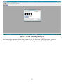
Figure 7: The middle column will echo back the status of the Analyze step with the green checkmark and two
black status bars at the bottom indicating Analysis has completed. Now setup your Alignment Points (AP)
options and create the AP boxes over the image as above by simply left-mouse clicking around the periphery of
the star disk to place the AP boxes.
IMPORTANT: When clicking and placing the AP boxes, don't let any boxes draw themselves onto the edges of the
star disk or this may skew the analysis results in WR. Overlap of the boxes is desirable, but no need to overdo it.
Usually somewhere between 8 and 12 alignment boxes is plenty good. If you need more than that to cover the star
image, adjust the AP box size slightly larger by 5-10 pixels. Just get some slight overlap box-to-box and that is good
enough. Don't worry about overlap in the center of the star disk....it isn't needed. If you mess up, just click the
"Clear" button to start over. Your AP box size will be determined by the diameter of the star disk. You'll need to use
a larger "AP Size" setting for larger star diameters and smaller for smaller diameters. Experiment to get an AP box
size that works to provide good overlap without causing an excessive number of boxes to be drawn. When you're
done with the AP alignment point boxes, click the "3) Stack" button.
Alternate Alignment Point Box Method: if your stacks were taken in very good seeing conditions and low
atmospheric turbulence, you can experiment with trying just ONE AP box that covers the entire image. Give it a try
and compare with the multi-box method to see if there are differences in the Strehl outcomes.
20
Figure 8: The middle column of the GUI will again indicate completion of the Stack process as shown above
with the two black progress bars and column of green checkmarks.
21
Figure 9: When AS has completed processing it will auto-save the master .tif file in a newly created folder
within the root folder the stack came from, and with a folder name similar to the highlighted one shown above.
For the Extrafocal stack, simply repeat these same steps on the Extrafocal .ser file.
22
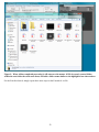
Figure 10: The resulting .tif files auto-saved by completion of the "3) Stack" step of Auto-Stakkert
Once you have run Auto-Stakkert to produce the master Intra and Extrafocal .tif files, you're ready to proceed to
prepping these master files for import into WinRoddier using the WRFITS utility.
23
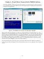
Chapter 6: Prep of Master Frames with the WRFITS Software
Glenn Jolly's "WRFITS" software app is used in the next phase of processing to prepare the files, convert them
over to .FITS files, scale the White and Black points of the images properly, and format the .fits file headers for
reading from inside WinRoddier.
Figure 11: The WRFITS GUI screen and "Get Input Image" Dialog Box
There are some initial setup parameters you will need to configure first before executing the "Input" step. In the
WRFITS GUI, UN-check the RGB box if you are shooting with a mono camera. Leave the "FixFits" box unchecked
in all cases unless the completed WRFITS files error-out inside WinRoddier. Also, type in the optical parameters of
the telescope and the pixel size of the camera. It is critical that if you shot the frames binned, fill in the bin value
(2x2 binning = "2" in the box above, for example). If you didn't bin the camera, leave it at a value of "1". If you
don't get the WRFITS binning matched up correctly with how you actually shot the frames, this will cause badly
inaccurate results inside WinRoddier, or may error-out WR completely.
After all the parameters have been setup correctly, now click the "Input" button and navigate to your folder that
contains the master Intra and Extrafocal .tif files that Auto-Stakkert created in the previous step. Select the Intrafocal
file first.
24
Figure 12: The feedback in the WRFITS GUI screen after executing the Input button
Note that the "Save" button is no longer grayed-out. Also note the feedback on the filenames and what WRFITS has
done up to this point in the blue window of the GUI. Now proceed on by clicking the "Save" button.
25
Figure 13: After clicking the Save button in WRFITS, browse to a folder of your choice and click the Save
button in the windows dialog box to save your Intrafocal master .fits file.
Now simply repeat these same steps for the Extrafocal .tif file and you're done! You are now ready to open the Intra
and Extrafocal .fits files inside WinRoddier.
Figure 14: The WFITS GUI and Save dialog box appearance.
26
I like to save the .fits files in the same root folder that Auto-Stakkert saved the .tif files to so I can keep them all
together. Just remember if you do it this way that it is the **.FITS** files you are opening from inside WinRoddier,
not the .TIF files! Click the "Done" button to close WRFITS.
27
Chapter 7: Analysis of Processed Master .FITS Files in the WinRoddier
Software
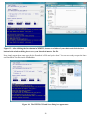
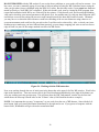
Figure 15: The WinRoddier GUI screen and "Preferences" Dialog Box
Start by clicking "Preferences" in the top menu row, then in the Preferences dialog box, click the "Algorithms" tab.
You can experiment with the "Maximum Number of Iterations" setting. The software default is "3", but with good
data taken in steady seeing, a setting all the way up to "7" can work well to reveal specific types of aberrations better
such as Astigmatism. You can leave all other settings in this tab at their defaults.
28
Figure 16: The Preferences >"Constants" tab
Set this screen up as shown above. The "Decimal Places" settings in the lower half of the screen are critical. If you
leave the Strehl box at its default of "0", your Strehl result will always just be rounded upward to a value of "1" for
most telescopes, which doesn't really tell you anything useful about the telescope's Strehl result. The Decimal Places
setting controls how many places out to the RIGHT of the decimal you want the calculation results to display. The
settings configured as above will work well in most cases.
29
Figure 17: The WinRoddier Preferences >"Adjustments" tab.
The number of polynomials is 22 for the software default. But again, with good data taken in steady air, you can
bump this setting up to 28 to get a slightly more detailed Strehl analysis. In the bottom portion of the screen, check
ON the boxes to subtract the Tilt and Defocus, but check OFF the box to subtract the coma. This allows a more
complete analysis by WinRoddier and will help indicate how well the scope is collimated in the final Strehl results.
Close the Preferences dialog box. It's now time to open WinRoddier and analyze the .fits files that were produced
from inside WRFITS.
30
Figure 18: WinRoddier File Selection Drop-Down
Click the File selection from the top menu row of WinRoddier. Then click the first "Open" selection on the dropdown list. Make sure you do not accidently first select "Open as Extra-Focal" from the drop-down list!!
31
Figure 19: The WR "Open Image" Dialog box
Now browse to the appropriate folder where you saved your .fits files in the WRFITS processing, select the
Intrafocal .fits file first and open it. You will now see the file open up inside the WinRoddier GUI.
32
Figure 20: Next, click on the "Open as extra focal" selection in the File drop-down list.
Figure 21: The WR "Open Extrafocal Image" dialog box
Select the Extrafocal .fits file next and open it inside WR.
33
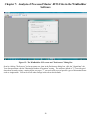
Figure 22: WR Test Parameters Dialog Box
Once the Intra and Extrafocal files are open, click the "Test Parameters" button at the far left of the button-bar at
upper left of WR screen. The Test Parameters window should now display the two file names as above, in correct
order within the correct window panes. Now, click the "Retrieve Information" button. Next, click the "Instrument
Used" tab along the top row of tabs in this window.
Note, if you somehow messed up and the Intra and Extrafocal files are both on the same side of the Test Parameters
window, or flipped around and reversed in the window, simply click on the file names and use the arrow buttons to
move and place them properly in the correct window pane.
34
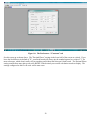
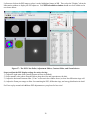
Figure 23: The "Instrument Used" tab
This is where you will type in the critical information about your telescope and camera. Pay attention to the "Binning
Used" box and get this right if you binned the image. After filling in all the values specific for your own telescope
and camera, now click the "calculator" mini-icon in the lower right corner of the Defocus dialog. This should now
display a value for defocus, expressed in millimeters of defocus. You should also see the radius values for Intra and
Extrafocal images. These two images should match up fairly closely in radius, to within about 2 pixels, or 3-4 pixels
if measured in diameter. (Remember radius is only ½ of diameter so the above example actually indicates a star
diameter of around 106 pixels which is within the ideal range for WinRoddier to analyze very accurately. Click the
OK button once you have clicked on the WR calculator button and gotten your defocus value to display.
Notes for the WR Defocus Calculator Field and General Troubleshooting inside WR3:
After clicking the WR Calculator button to display the amount of defocus in mm, this is a good time to "sanitycheck" your pre-calculated defocus you got earlier from the WRCALC utility and the radius of the star that WR is
reporting. The results for mm of defocus that the WR Calculator button gets should be within 1-2% of your
precalculated values in WRCALC *if* you used the same diameter star on-screen that you calculated for earlier, or in
terms of mm of defocus, about 0.2mm maximum variance for a typical amateur telescope. If they aren't, then one or
more of these things may have happened:
Intrafocal star defocus was significantly different than Extrafocal star (check this by what WR is telling you
for the Intra and Extrafocal star radii. Both star radii need to be within 3-4 pixels of each other for best WR
accuracy). Also, remember that star diameter is 2x the star radius if you have been working in diameter onscreen when shooting instead of radius.
One or more of the telescope and camera parameters was entered incorrectly. Go back and re-check all your
values, including the camera binning.
The Masking Value in WR is not correct. The default Masking is 50% in WR. Experiment with lower values
down to around 30% if your data was taken in good seeing, to see if this will correct.
35
DO NOT PROCEED with the WR analysis if you see the above problems, as your results will not be accurate. As a
last resort, you can try manually typing in your mm of defocus instead of using the WR Calculator button, using the
value you got when you pre-calculated using the WRCALC utility. But this only works if your actual star diameters
match up closely to what WRCALC calculated. If this trick doesn't work, next try closing the WR3 program, then
reopen and recalculate inside WR to see if this will fix the variance. If this doesn't work, and lowering the Masking
value and re-checking your entered parameters still doesn't fix it, the problem may lie with your data collection itself
and defocus on-screen star-sizing that was not careful enough between the Intra and Extrafocal stacks. Ultimately
you may have to re-shoot the data with more careful size-matching of the two star diameters using whatever onscreen measurement tools work best for you such as the Cross-Hare tool or other utility. Also, re-check your AutoStakkert steps to make sure you have followed them precisely, as poor image cropping (red-zone or star too close to
edge of frame) or poor AP box usage methods can skew the WR results.
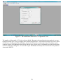
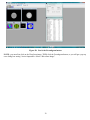
Figure 24: Working with the WR button-bar
Next, start working through the row of mini-icons in the button bar at the upper left of the WR window. Work left to
right on the button-row. Your next mouse click is the Wavefront button immediately to the right of the button you
were just working on in the previous step. This will now show the WR "Information" window for the first time
which shows the telescope's Strehl value as the "S/Smax" value (0.968 Strehl in the above example).
NOTE: It is important that you stay "in-sequence" as you work down the row of WR buttons. Start with the leftmost button, then work toward the button immediately to the right and so on. If you get out of sequence with the
button clicks, WinRoddier will give skewed or nonsensical data.
36
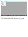
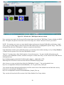
Figure 25: Next up is the Interferogram button.
PSF Image
Figure 26: Next is the PSF button.
There are some important "tweaks" to maximize the PSF image so that you can view the light energy distribution and
diffraction rings better. Use the following steps in this order after WR has generated the PSF image:
37
Left mouse-click on the PSF image to select it as the highlighted image in WR. Then select the "Display" tab in the
Information window to display the PSF adjustors. Your PSF Information window should now look similar to the
one shown below.
Figure 27: The PSF Color Pallet, Adjustment Sliders, Contrast Slider, and Zoom Selector
Steps to adjust the PSF display settings for easier viewing:
1) Adjust the right-most slider (usually downward from its default).
2) Select another color palette from the Palette drop-down list and (experiment with this).
3) Adjust the horizontal contrast slider ("Cont." as shown in the window above) to show the diffraction rings well.
4) Adjust the Zoom percentage to allow for examining the PSF, diffraction rings, and energy distribution in detail.
Feel free to play around with all these PSF adjustments as you please for best view!
38
Figure 28: Next is the Focaultgram button.
NOTE: you must first click on the Wavefront image, THEN click the Focaultgram button, or you will get a pop-up
error dialog box stating "Action Impossible--Select a Wavefront Image".
39
Figure 29: WR after the "RMS Spots button is clicked.
Note, you must once again click first on the Wavefront image, then click the "RMS Spots" button to display the RMS
data. The tighter the spots are toward the center of the image, the "cleaner" and more accurate your data is.
NOTE: If at anytime you want to see more detailed values and measures from the WinRoddier calculations, simply
click on any one of the images as shown in the main WR window above to highlight that specific image. Then click
through all the tabs in the "Information" window to explore the data further.
If the Information window gets accidentally closed, you can bring it back without starting over by clicking Windows
> View from the top menu row of the main WinRoddier window.
That's it!! You have done a basic Strehl analysis of your telescope now. For more detailed information on the
specifics of the WinRoddier software, and how to interpret its results more fully, see the website for the WR software
and help files here:
http://translate.google.com/translate?sl=fr&tl=en&js=n&prev=_t&hl=en&ie=UTF8&u=http%3A%2F%2Fwww.astrosurf.com%2Ftests%2Froddier%2Fprojet.html
Also, be sure to review my Quick-Start Guide for WinRoddier Version 3. You can download it here:
http://www.compubuild.com/astro/download/Roddier_Ver.3.0_Quick-Start_Guide.pdf
You can also download the Intra and Extrafocal .fits files used in most of this manual from the link below and try
them out for yourself inside WinRoddier Ver. 3:
http://www.compubuild.com/astro/download/Roddier_Sample_Files.zip
They can also be found in the Files section of the Yahoo Roddier Test Group website.
40
Chapter 8: Other Options for Further Processing Your WinRoddier
Results
IMPORTANT!! There is much more you can do with the WinRoddier analysis, thanks to the excellent work of
Glenn Jolly, and the Aberrator 3 and OpenFringe software development teams. You can now import the WinRoddier
data into Aberrator and OpenFringe for further analysis. I've prepared some How-To manuals for this. You can find
the manuals in the Files > WinRoddier Ver.3 section of the Yahoo Roddier Test Group, or you can download them
directly from my astronomy website. See Appendix 2 for a full set of links to all the software, Quick-Start Guides
and How-To manuals.
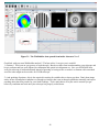
Figure 30: A sample of the WinRoddier data opened from inside OpenFringe Ver. 14
41
Figure 31: The WinRoddier data opened from inside Aberrator Ver. 3
Good luck with your own WinRoddier analysis!! The best advice I can give you is twofold:
1) Patience! This is not an easy process to work through. But the rewards come in understanding your telescope and
how it performs and how well-adjusted its collimation and optical axis alignment are. Now you will KNOW how
well your telescope is built and adjusted instead of guessing or having to take a vendor's or someone else's anecdotal
word for it that might not be accurate for YOUR telescope.
2) And speaking of patience, this is also required in waiting for suitable skies to shoot your data. Don't shoot image
stacks in lots of atmospheric turbulence or through a telescope that is not at thermal equilibrium internally and expect
anything other than lousy results for your Strehl readings. You're much better off to just wait it out until you get
better sky conditions and wait until your telescope has properly cooled down.
42
Appendix 1: Links to Software and User Guides
User Guides and Pre-WR Processing Software:
1) This User Guide: http://www.compubuild.com/astro/download/New_WinRoddier_User_Manual.pdf
2) The WinRoddier website: http://translate.google.com/translate?sl=fr&tl=en&js=n&prev=_t&hl=en&ie=UTF8&u=http%3A%2F%2Fwww.astrosurf.com%2Ftests%2Froddier%2Fprojet.html
3) The latest WinRoddier software: http://www.astrosurf.com/tests/roddier/WinRoddier3Pro.exe
4) WinRoddier Ver. 3 Quick-Start Guide:
http://www.compubuild.com/astro/download/Roddier_Ver.3.0_Quick-Start_Guide.pdf
5) WinRoddier Ver.3 Help files: http://www.astrosurf.com/tests/roddier/DocWinRoddier3.rar
6) How-To Guide for converting and using the WinRoddier Ver. 3 Help files to English:
http://www.compubuild.com/astro/download/Roddier_Ver.3.0_Help_Files-Conversion_to_English-Steps.pdf
7) Auto-Stakkert website: http://astrokraai.nl/autostakkert.php
8) Auto-Stakkert app, latest version: http://www.astrokraai.nl/software/AutoStakkert_2.2.0.12.zip
9) WRFITS app by Glenn Jolly: can be found and downloaded in the Files section of the Yahoo Roddier Test Group
(note, you will have to join this group to download the file from there):
Alternate download site:
http://www.compubuild.com/astro/download/WRFITS.zip
10) WRFITS How-To-Guide:
http://www.compubuild.com/astro/download/WRFITS_How-To-Guide.pdf
11) WRCALC star-diameter calculator utility:
Available from Yahoo Roddier Test Group or from this alternate download link:
http://www.compubuild.com/astro/download/WRCALC.zip
Helpful Software Utilities for Use During the WinRoddier Data Collection and for Telescope
Collimation prior to data collection:
1) CrossHare on-screen crosshair hashmark tool for accurately measuring defocused star diameters:
http://www.astrogeeks.com/AstroGeeks/CrossHare/index.html
2) MetaGuide software for fine-tuning your telescope's collimation. Also has Autoguiding tool and seeing
conditions analysis tool:
http://www.astrogeeks.com/Bliss/MetaGuide/index.html
3) FireCapture imaging app: http://firecapture.wonderplanets.de/
For further analysis of the WinRoddier data from inside Aberrator V.3:
1) Aberrator V.3 website: http://aberrator.astronomy.net
2) Aberrator Software: http://aberrator.astronomy.net/html/mdibeta.html
3) WinRoddier Ver. 3 to Aberrator How-To Guide:
http://www.compubuild.com/astro/download/Roddier_Ver.3-To-Aberrator_How-To_Guide.pdf
4) WR3OPD app by Glenn Jolly, to convert .OPD files from WinRoddier Ver. 3 for use in Aberrator V3:
http://www.compubuild.com/astro/download/WR3OPD.zip
Note, the WR3OPD .zip file at the above file contains a "Readme" file that explains how to install and use the
WR3OPD executable file from inside a DOS command or "CMD" box in Windows XP/7, etc....
For further analysis of the WinRoddier data from inside the OpenFringe app:
1) OpenFringe Yahoo Interferometry User Group:
http://groups.yahoo.com/neo/groups/interferometry/conversations/messages
2) OpenFringe App is found in the Files section of this group. Note, you will need to join this group to get the latest
OF executable file: http://groups.yahoo.com/neo/groups/interferometry/files
3) WR2OF Roddier-To-OpenFringe Zernike converter app by Glenn Jolly is found in the Files section of the Yahoo
Roddier Test Group
43
4) Alternate Download Site: http://www.compubuild.com/astro/download/WR2OF.zip
5) Roddier-To-Open Fringe How-To Guide:
http://www.compubuild.com/astro/download/Roddier-To-OpenFringe_Quick-Start_Guide.pdf
44
Appendix 2: Math Calculations for Correct Amount of Defocus
Roddier Defocus Calculations to produce 15 waves of defocus with various cameras
Use these formulae to pre-plan for the correct star image diameter before the shoot:
Step 1: Find "theta" for the specific scope to be analyzed
Wavefront angle = "theta"
Formula for theta:
theta = arctan of [D/2 divided by efl]
where,
D = lens or mirror diameter
efl = effective focal length of telescope
Therefore, using the Royce RDK-10 telescope as an example:
D = 254mm
efl = 5080mm
Video Camera: Lumenera Skynyx-2-2c with 4.4 micron pixels
theta = arctan [254/2 divided by 5080] = 1.42321 degrees
**arctan = inverse of tan** (first click the "Inverse" button on the Windows Scientific calculator, then click the
"Tan" button to calculate the value).
1.4321 degrees = 0.0249948 radians
***Always express theta in radians when using these Roddier formulae---with the Windows on-screen calculator set
to scientific mode, select the output as Radians when calculating tan or arctan***
STEP 2: Find the defocus in mm ("dz") for a given on-screen pixel radius of the test star image:
So for a pixel diameter of 100 pixels (or radius of 50 pixels) with a camera pixel size of 4.4 microns, the amount of
defocus in mm ("dz") is as follows:
1.4321 degrees = 0.0249948 radians = arctan of [50 x 0.0044/dz]
where,
dz = [50*0.0044/tan[theta angle expressed as radians from above formula result]
or,
dz = [50*0.0044]/tan[0.0249948] = 8.80mm of defocus on this scope with this camera (4.4u pixel size) using a
star image size of 100mm diameter (50 pixel radius) ***NOTE: this should agree with the
Roddier
"Calculator Button" output that the Roddier software displays for its defocus value.
STEP 3: Convert mm of defocus to waves of defocus ("dn"):
To convert 8.80mm of defocus in the above example to waves of defocus ("dn"):
45
dn = dz divided by [8*F^2*lambda expressed in mm of light's wavelength--Green is 555nm or 0.000555mm]
where,
F = focal *ratio* (not focal length) of scope
Example:
dn = 8.8/[8*20 squared*0.000555] = 4.95 waves of defocus (way too small of a star-test pattern to meet our criteria
of 15 waves of defocus)
STEP 4: Find the correct on-screen test-star display size that produces enough defocus to allow WinRoddier
to analyze the images accurately (approx. 15 waves of defocus needed by WinRoddier):
Therefore, to achieve the desired 15 waves of defocus for the f/20 Royce RDK-10 with a
4.4 micron pixel-sized camera at Green wavelength of 555nm, the following calculation is made:
From Step 3 above, reviewed here:
dz = mm of defocus to get 15 waves defocus = 15 waves*[8*20 squared*0.000555] = 26.64mm of defocus
Correct pixel size for 15 waves defocus = [26.64*[tan 0.0249948 radians]] divided by 0.0044 mm = approx. 151 pixel
radius
To Convert mm of defocus to waves of defocus at given wavelength:
dn (defocus in waves) = dz divided by [8F^2*lambda]
where,
F^2 = focal ratio of scope squared
lambda = wavelength of light used in same units as "F^2" (usually expressed in mm and usually the Green bandwidth
midpoint of
0.000555mm, or 555nm.
So to review, for the Royce RDK-10 scope using a 4.4u pixel-sized camera:
Pixel radius of image for 15 waves defocus = [26.64mm*tan(0.0249948)] divided by 0.044 = 151 pixel radius
(or 302 pixel diameter defocused star-size test pattern). You can see from this, you'll have to bin the camera 2x2 to
get the image diameter down to 151 pixels so it will meet the optimum size range inside WinRoddier.
Royce RDK-10 with other Cameras (**NOTE: the smaller the pixel size of the camera, the LARGER the on-screen
test-star image size will have to be to produce the desired minimum 15 waves of defocus---the relationship is a linear
ratio based on each camera's pixel size in microns).
Example calculation results specific to the Royce RDK-10 scope:
Need 532 pixel diameter unbinned test-star image for 15 waves of defocus with Flea-3 (2.5u pixels)
Need 300 pixel diameter unbinned test-star image for 15 waves of defocus with Lumenera (4.4u pixels)
Need 360 pixel diameter unbinned test-star image for 15 waves of defocus with ASI120/QHY5L-II (3.75u pixels)
**For all the above results with the RDK-10 scope, you would need to bin 2x2, and you would also need a camera
with pixel sizes in the 4.4-7.4 micron size range for best results in analyzing this particular scope.
NOTE: A good target working range of defocus for best results in WinRoddier is 20-30 waves of defocus.
46
Table Showing Amount of Defocus with Various Telescopes and Cameras
Remember the optimal WinRoddier parameters:
15-20 waves is the *minimum* amount of defocus required for best results with WinRoddier, with 20-30 waves of
defocus being the optimal target range.
The target diameter size range for the on-screen star display in WinRoddier is 100-150 pixels whether binned 2x2 or
unbinned.
Telescope
6 in. Refractor, 1200mm
f.l., f/8 f.r.
6 in. Refractor, f/8
C8 SCT, f/10
C11 SCT, f/10
C14 SCT, f/11
120mm Refractor, f/7.5
120mm Refractor, f/7.5
Video Camera
Lumenera Skynyx 2-2, 4.4u
pixels
QHY5-LII, 3.75u pixels
DMK-41, 4.65u pixels
ASI-120MM, 3.75u pixels
QHY5-LII, 3.75u pixels
Flea-3-U3-32, 2.5u pixels
QHY5-LII, 3.75u pixels
mm/Waves of Defocus in
WinRoddier
7.1mm, 25 waves
Pixel Diameter of Star @
stated defocus value
102 pixels, binned 2x2
6.3mm, 22 waves
9.8mm, 22 waves
8.9mm, 20 waves
9.7mm, 18 waves
4.5mm, 18 waves
6.2mm, 25 waves
106 pixels, binned 2x2
105 pixels, binned 2x2
118 pixels, binned 2x2
117 pixels, binned 2x2
120 pixels, binned 2x2
110 pixels, unbinned (1x1)
Table 3: Defocus vs. On-Screen Star Diameter Sizes for Various Telescopes and Cameras
47
Appendix 3: Credits and Thanks
Glenn Jolly, for his WRCALC, WRFITS, WR2OF, and WR3OPD apps, and the time spent helping me with
beta-testing all the software and also for helping me with the optical calculations and optical theory.
John Biretta of the Yahoo Roddier Test Group, for his original Roddier Cookbook, and the help he has given
me over the years in learning how to use the WinRoddier software.
Claude Roddier and Francois Roddier, for their work in producing the original WinRoddier research paper.
The WinRoddier development team at AstroSurf in France, for providing us with the WinRoddier Ver. 2.2
and Ver. 3 software.
Mark Crossley of the Yahoo Roddier Test Group, for providing an English version of the WinRoddier
software.
Frank "freestar8n", for his initial help with discussing the extra analysis possibilities of WinRoddier, and for
his MetaGuide software which is an excellent fine-tune collimation tool for your telescope.
Ray St. Dennis of AstroGeeks.com, for his CrossHare app.
The OpenFringe Interferometry development team, for providing us with the free OpenFringe software.
Cor Berrevoets, for providing the free Aberrator Ver. 3 software to us.
Torsten Edelmann, for his FireCapture imaging app.
Thanks to all the above folks! Because of their generous assistance and software development, we now have a very
effective and inexpensive way to analyze the performance of our telescopes without having to rely solely on
anecdotal end-user reports, or the word of vendors without data to back it up.
Disclaimer:
This WinRoddier manual is provided for free via download from the link shown earlier in this document. It may be
freely distributed to others. You can also find it in the Yahoo Roddier Files section if you are a member of that
online group. It is forbidden to alter the form or content of this document in any way without the expressed written
permission of Wade Van Arsdale, its author.
© 2013 Wade Van Arsdale
Revision 1.4, 12/11/2013
48