1
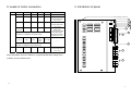
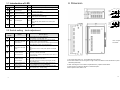
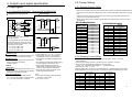
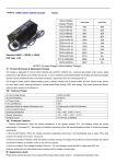
VER. 2204-07-06-01
High Performance
2 P h a s e St e p M o t o r D r i v e r
DPYHHAB2400000000
DPYHHAB2600000000
User Manual
【Index】
1. The summary…………………………………… P.1
2. The confirmation of content of package……… P.1
3. Introduction of the panel………………………… P.2
4. Output/ input signal specification……………… P.5
5. Connecting diagram……………………………… P.8
6. Function option and current adjustment……… P.9
7. Specification table……………………………… P.11
8. Dimensions……………………………………… P.12
9. The connecting of in common use motors’ brand……..P13
● If any change in the performance and specification, appearance of products all take
as the material object, no separate informs. Respectfully supplicate understanding.
● Products inquiry or if any question in use are welcome to contact us.
Please read and be familiar with the notices of specification
and security in the user guide before to use the driver.
Please reserve this user guide for looking up at any time.
1. The summary
The dirver is the appropriative driver which offer bipolar connecting method, it’s just for the 2
phase stepper motor. Utilize CPLD component design to reduce internal components
enhance confidential, SMT component design has a lot of merits, as scaling bulk and
to
stable
quality; unique drive technic and protection function enhance the speed of motor, acceleration
and torque output。The feature are as follows:
• Excite mega tic method: Full step is 2 phase excite mega tic,each step 1.8 degree. Half
step is 1-2 phase excite mega tic, each step 0.9 degree.
• Drive method: Bipolar driving with constant current, there are a lot of merits, as
the angle accuracy is better and torque is larger and so on….
• Special function:1P/2P function for option、over heat protection(OVH)、auto-adjustment
current (ACD)、external mega tic release (C.OFF)、self-test and zero timing
output (ZRO) and so on….
• Output signal:There is over heat and zero timing output, it can auto-control with external
circuit.
2. The confirmation of content
The content of package is listed below for confirmation; please check out after taking off a
seal, if any damage or lack, please contact us at once.
• The Driver………………………………………………………………………
1unit
• Moveable sockets ( It had be inserted in driver)
10 holes…………………………………………………………………………
1piece
• Accessories
Pan Head cross M3 screw …………………………………………………… 2 piece
• User guide (This book)…………………………………………………… … … 1 book
14
1
9. Leads of motor connection
TECO
3. Introdution of panel
A
/A
B
/B
4 leads
black
green
red
blue
----
6 leads
black
green
red
blue
Yellow, white: don’t
Fan voltage is DC12V
connect and forbid
1
short circuit
6 leads
8 leads
Red
red
red white
black
green
green
green white
yellow
(Series)
Series connection: double impedance, quadri- inductive
reactance, it is suitable for low speed runing.
8 leads
(Parallel)
Red、black black、red
white
white
green、
yellow、
yellow
green white
2
Black, white: don’t
3
connect and forbid
5
short circuit
Connect red white and
black white
Connect green white
and yellow white
Two group of leads:
forbid short circuit
7
12
14
----
white
13
Parallel connection: halve impedance, inductive reactance
constant, it is suitable for high speed runing.
VEXTA
6 leads
black
green
red
~
blue
Yellow, white: don’t
connect and forbid
short circuit
15
Above information is just for reference, if original manufactuere change color
of leads, we won’t further inform.
16
13
2
4
6
11
3.1 Introduction of LED
LED
1
2
3
4
PWR
Name
Power light
CW
Clock-wise light
CCW
Count clock-wise light
COF
Excite mega tic release
light
ZRO
Zero timing light
5
6
OVH
Over heat light
Color
8. Dimension
Description
Green When the driver accept AC11, PWR will be light.
0.24 (6.0) 0.94 (24.0)
0.00 (0.0) 0.59 (15.0) 1.18 (30.0)
When the driver receive pulse signal, CW will blink
Green
once each pulse signal.
When the driver receive pulse signal, CCW will blink
Green
once each pulse signal.
When the driver receive external excite mega tic
Red
release signal, COF will be light.
When full step, ZRO will blink once each 4 pulse
signals.
Green
When half step, ZRO will blink once each 8 pulse
signals.
When the temperature of driver is over 85°C, OVH will
Red
be light.
0.00 (0.0)
0.28 (7.0)
0.47 (12.0)
厚度 1mm
孔徑φ5
0.00 (0.0)
0.14 (3.5)
0.28 (7.0)
0.24 (6.0) 0.94 (24.0)
0.00 (0.0) 0.59 (15.0) 1.18 (30.0)
0.00 (0.0)
0.28 (7.0)
0.55 (14.0)
0.75 (19.0)
厚度 2mm
孔徑φ5
3.2 Switch setting、knob adjustment
Switch &
Knob
7
Name
9
10
11
12
13
setting
Description
In normal running, to set the switch GO.
When self-test, to set the switch TST.
If use CW pulse and CCW pulse to control the running
2P/1P
Option switch for pulse
direction of motor, to set the switch 2P.
2P
If just only input a group of pulse, another signal control the
control method
running direction of motor, to set the switch 1P。
If have motor to run1.8° each pulse, please use FL( full
FL/HF
Option switch for angle
step)。
FL
If have motor to run 0.9° each pulse, please use HF(half
of step
step)。
When motor stop, if want to have the drive current
OF/ACD
Function switch for
auto-down, to set the switch ACD。
ACD
When motor stop, if want to maintain fixed drive current, to
auto-current down
set the switch OF.
When the driver is over heat(>85°C), if want to have the
OF/AHO
Function switch for
motor stop, to set the switch AHO。
AHO
If to set the switch OF; it will only output signal, but the
over heat output
motor wouldn’t stop.
Knob for adjustment of
To set 16 step of the drive current, when the motor run.
RUN
8
running current
(1.0~4.0A,MSD2204,(1.5A~6.0A,MSD2206)
Knob for adjustment of
To set percentage of current down, when the motor stop.
STOP
8
stop current
(15%~100%16 step,16 step setting)
GO/TST Self-test switch
8
Original
GO
Unit:Inch(mm)
37% Scale
1. The screws size is M3*0.5 ㎜ and dimension are as above.
2. If the driver needs to run for a long time or high current, it is better to mount the driver in a place
decreasing heat easily.
3. When mounting two or more drivers, separate them by a space at least 20mm.
4. Don’t expose to continuous vibration or excessive impact。
5. Don’t expose to dust, water or oil.
12
2
3
7. Specification
Model Name
2 phase step motor driver
Drive method
Bipolar Driving with Constant Current
Drive current
Drive mode
Input Signal Specification
3.3 Connection Terminal
1.0A ~4.0A DPYHHAB2400000000
Code
CW+
Full Step:1.8°/step
Half Step:0.9°/step
CW-
Input Resistance: 220Ω、Input Current under 20mA
CCW+
2P:clockwise pulse input
14
1P:pulse input.
Negative Lever Excite, Pulse Width above 5 u Sec
DIR/CCW signal input
CCW-
2P: counterclockwise pulse input
1P: direction input (OFFÆCCW,ONÆCW)
Noise isolation
Function switch setting
LED indication
Cooling method
COF+
Use of Open Coupler
COF-
Pulse input method, Step angle(resolution), Auto current
down function, Auto overheat signal output selection.
ZRO+
PWR LED, CLK LED, ZRO LED, COF LED, OVH LED
ZRO-
Heatsinks
Temperature
0 ~ 40°C
OVH+
Moiture
< 85%RH
Power
AC85V~265V , 50/60Hz
OVH-
A
/A
B
Dimension (mm)
Weight
185(L) x 107(W) x 52(H)
DPYHHAB2400000000
207(L) x 109(W) x 69(H)
DPYHHAB2600000000
15
FG
1280g (DPYHHAB2600000000)
16
FG
AC110V
Description
Page
• 2P drive method
− The pulse input terminals which have the motor
CW.
• 1P drive method
− The pulse input terminals which have the motor
running.
P.5
• 2P drive method
− The pulse input terminals which have motor
CCW pulse input terminals CCW.
/gyro-direction pulse input • 1P drive method
− The pulse input terminals which control the
terminal
running direction of the motor.
(“L”ÆCCW, “H”ÆCW)
P.5
• When add a High voltage in this point, the current of
the driver would down to zero at once, then torque
of the motor is released.
P.6
• When full step (1.8°/step),the driver receive each 4
Excite mega tic zero timing pulses, this point will output a signal.
signal input terminal
• When full step (0.9°/ step), the driver receive each 8
pulses, this point will output a signal.
P.7
Excite mega tic release
signal input terminals
Over heat input terminal
Motor wiring terminal
• When the temperature of driver is over 85°C, this
point will be active at once。
• Motor A phase。
• Motor /A phase。
• Motor B phase。
P.7
P.8
• Motor /B phase。
/B
1020g (DPYHHAB2400000000)
AC110V
11
CW pulse input terminal/
Pulse signal input terminal
Voltage:+4~+10V、L:0~+0.5V
Negative Lever Excite, Pulse Width above 5 u Sec
PLS/CW signal input
Name
1.5A~6.0A DPYHHAB2600000000
Ground terminal
• Ground of AC input (connected to case)
Power input terminal
• Single phase AC85V~AC265V ± 10%, 50/60Hz
P.8
4
4. Output/ Input signal specification
6.2 Current Setting
4.1 Input Signals
6.2.1 Running Current (RUN)
4.1.1 Pulse/CW (PLS/CW)、Direction/CCW (DIR/CCW)
•Input Signal Connecting Circuit
Control Interface
Driver Inner
V0
PLS
(CW)
PLS(CW)
220Ω
• Pulse Diagram
1P Mode
OFF
H
L
ON
5μs
5μs
above above
DPYHHAB2400000000
R
2μs
below
Å25mA below
DIR
(CCW)
DIR(CCW)
PULSE
90%
10%
220Ω
2μs
below
Å25mA below
「RUN」scale
Running
current(A/phase)
0
1
2
3
4
5
6
7
8
9
A
B
C
D
E
F
1.0
1.2
1.4
1.6
1.8
2.0
2.2
2.4
2.6
2.8
3.0
3.2
3.4
3.6
3.8
4.0
DIRECTION
OFF
H
CCW
R
• When motor is rotating, driving current could be set by ”RUN” non-segments adjustment knob.
• If the driving current of driver is higher than motor’s, motor could easily cause heat, even burn
out.
• If the driving current of driver is lower than motor’s, the torque and speed performance of
motor is not so much better than high.
• Driver factory setting at the 8 location, please refer to the suitable output current of motor’s
specification.
L
ON
CW
20μs 10μs
above above
2P Mode
( ) means 2P mode
If V0= 5V, it doesn’t need to connect
external resistor R.
CW
H
L
If V0 is higher than 5V, you should connect
an external resistor R. The input current
must stays under 20mA, otherwise, it will
burnout the photo-coupler.
** V0= 12V, R=1.0KΩ / ¼W
** V0= 15V, R=1.5KΩ / ½W
** V0= 24V, R=2.0KΩ / ½W
90%
10%
5us
5us
above above
2μs
below
2μs
below
CCW
H
L
10μs
above
2P Mode
• CW Pulse Input
When the negative trigger pulse input the CLK
terminal, the motor will rotate in clockwise.
• CCW Pulse Input
When the negative trigger pulse input the DIR
terminal, the motor will rotate in
counterclockwise.
• Pulse Voltage, H = +4~+10V, L = 0~+0.5V.
• Pulse wide is above 5μs . The alternate
time between H and L must be under 2μs.
• The maximum accessible chopping speed
is 60KHz.
• The response time between direction signal
and pulse signal must be above 10μs.
• Using negative trigger technique is to
1P Mode
isolate noise, so before this terminal input
• Pulse Input
pulses, it needs to keep in High status.
When the negative trigger pulse input the CLK • When 2P input, please don’t input CW &
terminal, the motor will rotate, and the direction
CCW pulse at the same time.
will depend on the direction signal.
• Direction Signal input
Note:
When direction signal input DIR terminal,
If motor rotate oppositely, please exchange
If ″L″, the motor will rotate in counterclockwise.
connection of A, B phase.
If ″H″, the motor will rotate in clockwise.
Ex. A Æ B or /A Æ /B
5
DPYHHAB2600000000
「RUN」scale
Running
current(A/phase)
0
1
2
3
4
5
6
7
8
9
A
B
C
D
E
F
1.5
1.8
2.1
2.4
2.7
3.0
3.3
3.6
3.9
4.2
4.5
4.8
5.1
5.4
5.7
6.0
6.2.2 Stopping Current (Stop)
• When the motor stop run, its current value can be set by the「STOP」of 16 step
micro adjustment.
• If use current auto-drop function, it can be set by the「OF/ACD」of switch。
• Knob can adjust descendant percentage for range 0%~85%.
「RUN」x (1-descendant percentage %) = current when stop
• Knob scale 0 Æ 85%,F Æ 0%
• Original setting value of driver is in the middle (scale 8),please according to real needs
to adjust digressions for the current value, it is helpful to reduce temperature of the motor.
[STOP]scale
0
1
2
3
4
5
6
7
current down
(percentage%)
85
80
75
70
65
60
54
60
[STOP]scale
8
9
A
B
C
D
E
F
current down
(percentage%)
42
36
30
24
18
12
6
0
10
6. Function setting and current adjustment
6.1 Function setting
4.1.2 Excite mega tic current release (COF) Signal
6.1.2 Pulse input method
6.1.1 Self-test switch
• If move this switch to the place
TST • This switch is for driver self-test.
GO
• If move this switch to the place
2P
1P
「GO」, it means common running
means just only to use a group pulse
• If move this switch to the place
6.1.4 Current auto-drop function
• If move this switch to the place
• If move this switch to the place
「ACD」, it means after motor
「FL」, it means the motor will run
stop about 0.3 sec,the driver will
with full step method,each step is
OF
ACD
according to the setting of current
motor over heat.
(Regarding current descendant
0.9°, to run a circle need 400
percentage, please refer to P.10
pulses.
「current adjustment」)
• If move this switch to the place
of the drive is over 85°C, except
If V0 is higher than 5V, you should connect
an external resistor R. The input current
must stays under 20mA, otherwise, it will
burnout the photo-coupler.
** V0= 12V, R=1.0KΩ / ¼W
** V0= 15V, R=1.5KΩ / ½W
** V0= 24V, R=2.0KΩ / ½W
auto-drop drive current to avoid
with full step method,each step is
「AHO」, it means when temperature
Å20mA Below
descendant percentage to
「HL」, it means the motor will run
• If move this switch to the place
R
If V0= 5V, it doesn’t need to connect
external resistor R.
6.1.3 Step angle setting
6.1.5 Over heat auto-protection input
COF
input terminal.
5Hz to drive motor.
• If move this switch to the place
220Ω
direction of motor by ON/OFF of CCW
the driver will bring pulses about
pulses.
COF
input (CW),and to control CW/CCW
「TST」, it means self-test model,
1.8°, to run a circle need 200
Driver Inner
V0
group is CW pulses,another one group
• If move this switch to the place 「1P」, it
control.
HF
Control Interface
means to use 2 groups pulses input; one
is CCW pulses.
model, the driver accept external
FL
「2P」, it
• Input loop signal connecting diagram
「OF」, it means when the motor
stop, the driver still maintains
original current, no auto-drop
function.
• When ″COF″ terminal is active, the driver
will release current. Motor now is without
torque, it could easily rotate shift by hand.
• The terminal is negative trigger, when it is
not active, it remain at H status.
• When COF is active, and there is external
force to rotate the shift. There will have
+/-3.6 degree tolerance after COF
release.
output alarm signal and auto-release
OF
AHO
drive current ( The motor stop)。
• If move this switch to the place「OF」,
it means temperature of the driver is
over heat, just only OVH LED light
and output the over heat signal, but
the drive current won’t be released
(The motor keep running).
9
6
5. Connecting diagram
4.2 Output signal
4.2.1 Zero Timing Signal(ZRO)
• Output Signal Connecting Circuit
Control interface
Control panel output
Driver
+5V
The interior of driver
CW/ pulses input
V0
CW
CW
R
ZRO
CCW/ direction input
ÅUnder 10mA
CCW
CCW
V0 voltage 5~24V。
Add external impedance R, forbid
connecting circuit current is over 10mA。
Excite megatic release COF
COF
+5V
• There is a Zero-point output when the motor rotated per 7.2°. For example as following:
When
4 pulse(OVH)
input, one Zero signal output.
4.2.2200s/r(1.8°/s):Per
Overheat Signal
When 400s/r(0.9°/s):Per 8 pulse input, one Zero signal output.
In the mean time, the ZRO LED light on when Zero signal output.
• For best zero timing performance, it is combined with mechanical zero timing together.
• Output Signal Connecting Circuit
控制介面輸出
Control
Interface
ZRO
A
ZRO
/A
OVH
B
OVH
/B
Overheat signal output
驅動器內部
Driver
Inner
V0
R
ZRO
OVH
Å10mA 以下
以下
The
V
range of5~24V。
voltage, V0, is between 5V to 24V.
0 電壓值
加上外部阻抗
R,接線回路電流勿超過
The
current is under
10mA.
10mA。
7
• When temperature is over 85°C, the driver
will output an alarm signal. OVH LED light
on at the same time. It protects inner
components in driver PCB.
• If function switch on OF/AHO, driver not
only output overheat signal and light on, but
also decrease excite mega tic current, then
motor stop.
• In operating status, when alarm signal
happened, you should turn off the power
immediately. After find out the reason and
wait for the driver is cool then restarts it.
FG
Ground
AC110V
AC110V±10%
50/60Hz
AC110V
• Regarding the allocation of motor leads’
color of each phase, please refer to P.13 or
the user guide of each brand.
8