1
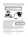
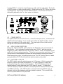
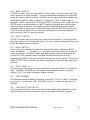
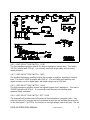
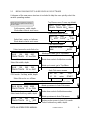
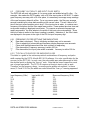
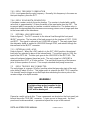
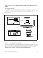
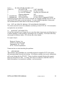
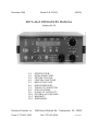
November 1996
Manual P/N 700-011
080599
DSTS-4A/3 OPERATORS MANUAL
Software V4.XX
1.0
2.0
3.0
4.0
5.0
6.0
7.0
8.0
9.0
10.0
11.0
12.0
INTRODUCTION
INITIAL INSPECTION
GETTING STARTED
CONTROL FUNCTIONS
MENU STRUCTURE
ERROR MESSAGES
THEORY OF OPERATION
SPECIFICATIONS
IN CASE OF DIFFICULTY
OPTIONAL ACCESSORIES
WARRANTY
ADDENDUMS
Electronic Devices Inc. 3140 Bunch Walnuts Rd. Chesapeake, VA 23322
Phone 1-757-421-2968
Fax 1-757-421-0518
DS4OPT4MA3
1
INTRODUCTION
The DSTS-4A is a precision instrument designed for evaluation and repair of all types
of depth sounders. It is capable of measuring the incoming pulse parameters and
generating a reply echo pulse over a very wide range of frequencies. For further
information refer to the specifications. The micro-processor in the DSTS-4A controls all
functions with the exception of the reply level. The incoming pulse is analyzed and
displayed on the top line of the display. Outgoing parameters are displayed on the
bottom line. Applying power to the DSTS-4A resets the processor and displays
"WAITING FOR A PULSE". This message will remain on screen until the first pulse is
received. Within three pulses the DSTS-4A begins to display and average the input
information. The output frequency, depth, and pulse width are automatically set. To
check the depth sounder under test (DUT), read the top line of the display to confirm
the pulse parameters and adjust the reply level to measure the receiver sensitivity.
Depth calibration can be done in feet, fathoms, or meters. The velocity of propagation
is 4800 feet/second in the foot and fathom range, and 1500 meters/second on the
metric range.
2
INITIAL INSPECTION
Unpack the DSTS-4A. The shipping box will contain a wall plug power supply, manual,
and any accessories you have ordered. Check the contents against the packing list
and also check for mechanical damage. Please report any discrepancies to EDI as
soon as possible. Save the shipping box should you need to return the unit.
2.1
PRELIMINARY ELECTRICAL TEST
Note: Do NOT connect a depth sounder to the DSTS-4A for this test.
The DSTS-4A comes with a wall plug transformer. This transformer is rated for
110-120 VAC 50-60 Hz current. If you have
220 VAC, use a 12 VAC, 500mA adaptor or
Waiting for a pulse
order the optional 220 VAC transformer unit.
EDI DSTS-4A/3
V4.XX
Plug the transformer into the mains and
connect the end of the cord to the power
DSTS-4A Start-up display message
connector on the back panel of the DSTS.
Turn the power switch on. The startup
message shown will appear on the liquid crystal display (LCD). This indicates the
processor has passed the internal diagnostics. Depress and hold both the FREQ and
MODE switches momentarily. The message should change to " Up/Dn *Auto Pulse
Mode* ". The DSTS-4A will now put out a train of pulses at a frequency of 100 KHz.
The frequency may be varied from 10 to 650 KHz using the FREQ switch. To restore
the DSTS-4A to normal operation, momentarily raise the MODE switch. This
completes the initial inspection and test of the DSTS.
3
GETTING STARTED
Reset the DSTS-4A by lifting the MODE switch momentarily. Set the LOAD
SELECTION switch to LOW. Set the REPLY LEVEL switch to 50 mV.
DSTS-4A OPERATORS MANUAL
Hardware revision 3
2
Connect a depth sounder to the IN/OUT BNC connector. Refer to figure 1, showing
the optional BAL-550, to connect depth sounders with two wires and a shield. Apply
power to the depth sounder. The PULSE LED will flash each time the depth sounder
transmits, and the message "WAITING FOR A PULSE" will disappear. After receiving
CAUTION - never set the LOAD SELECTION switch to EXT LOAD
without an external load plugged in. Some depth sounders can be
damaged if operated into an open circuit.
FIG 1
the third pulse, the top line will display the incoming frequency, width, period, and
peak-to-peak voltage. The frequency and voltage are averaged and will stabilize after
ten or more pulses have been received. The depth defaults to twenty feet when power
is applied. The time that it takes for the
readings to stabilize is based on the pulse
191.9_ 00911 0198 1220
repetition rate and pulse width of the DUT.
TRACK TRACK 020.0 Menu
Depth sounders that have high pulse
DSTS-4A display with pulse input
repetition rates will produce a nearly
instantaneous reading, while deep water
sounders with pulse rates of one or less per second will take longer. Depress the
MODE switch to select the calibration menu. From there, choose feet, meters or
fathoms, Lifting the MODE switch will return you to the main display. Measure the
receiver sensitivity by reducing the REPLY LEVEL to the point where the echo just
disappears. This completes the most basic mode of testing.
4
CONTROL FUNCTIONS
Refer to figure 2 for control identification. The four switches below the display control
the advanced operating features of the DSTS-4A. The first three grouped under the
DSTS-4A OPERATORS MANUAL
Hardware revision 3
3
heading "REPLY" control the output frequency, width, and the reply depth. The fourth,
or MODE switch is a multi- purpose switch. Lifting it returns the DSTS-4A to the normal
operating mode. Depressing it selects different menus, such as the CAL menu for
setting the calibration units, i.e., feet, meters, or fathoms.
20.0 Menu
Fig 2
4.1
POWER SWITCH
The power switch turns the DSTS-4A on, resets the microprocessor, and restores all
default modes and settings. For a normal reset, where the depth and other manual
settings are retained, lift the mode switch. The power switch has no effect on the
charge rate of the optional internal battery pack.
4.2
REPLY GROUP SWITCHES
Moving the FREQ or WIDTH switch will place the DSTS-4A in the manual mode for
that function. This is indicated by replacing the word "TRACK" with the selected
frequency or width. When the DSTS-4A is in the "TRACK" mode, the frequency and
width track the input pulse parameters. This is the most commonly used mode. Some
microprocessor-controlled depth sounders will have randomly varying pulse widths.
When testing these units, the width must be in the "TRACK" mode so the echo width
generated by the DSTS-4A will match the depth sounder’s pulse width.
4.2.1 FREQUENCY SWITCH
The FREQ switch varies the reply frequency in .1 KHz steps. Lift it to increase the
frequency, depress it to lower the frequency. The rate of frequency change will
increase the longer the switch is held in position. The DSTS-4A operates in the
manual frequency reply mode after the FREQ switch is moved. To restore the
"TRACK" frequency mode of operation, momentarily lift then release both the FREQ
and WIDTH switches. If the FREQ switch is released before the WIDTH switch is
released, then only the frequency auto track mode is restored. This is useful if the
value of a preset width is to be preserved.
DSTS-4A OPERATORS MANUAL
Hardware revision 3
4
4.2.2 WIDTH SWITCH
The WIDTH switch varies the reply width in 1 uSec steps. Lift it to increase the reply
width, depress it to lower the width. The rate that the width changes will increase the
longer the switch is held in position. The DSTS-4A operates in the manual width reply
mode after the WIDTH switch is moved. To restore the "TRACK" width mode of
operation, lift then release both the FREQ and WIDTH switches at the same time. If the
WIDTH switch is released before the WIDTH switch is released, then only the width
auto track mode is restored. Some depth sounders deliberately vary pulse widths
during operation to reject noise. When testing these units the WIDTH must be in the
"TRACK" mode so the DSTS-4A’s reply echo will follow the input pulse variations. If
this is not done, the DUT may not respond.
4.2.3 DEPTH SWITCH
The DEPTH switch varies the reply echo depth in tenth unit steps. Lift it to decrease
the depth, depress it to increase the depth. The rate of depth change will increase the
longer the switch is held in position.
4.3
MODE SWITCH
Refer to the menu diagram in section 5 for further information. Lifting the MODE
switch will display “----- Resetting -----” on the top line of the display and moves the
menu up one level. Frequency, width, and depth settings remain as previously set,
and the DSTS-4A frequency measuring gate will adjust for the best accuracy.
Depressing the MODE switch will cycle down through the various menus. Refer to the
MENU STRUCTURE in section 5 for further information on the mode and reply group
switches.
4.4
REPLY LEVEL mV
The reply level switch varies the reply level from 10 microvolt (.01mV) to 50 millivolts
RMS. The AMPL VERNIER must be rotated to the maximum counter clockwise
position (CAL 1X) to obtain the output voltage selected.
4.5
AMPL VERNIER
The amplitude vernier multiplies the setting on the REPLY LEVEL switch. If the reply
level is set to .2 mV and the AMPL VERNIER is set to 1.5, the actual reply level is .3
millivolts.
4.6
LOAD SELECTION SWITCH
The load selection switch selects from one of three internal load impedances or the
external load jacks on the front panel. Refer to the partial schematic in figure 3.
DSTS-4A OPERATORS MANUAL
Hardware revision 3
5
4.6.1 LOAD SELECTION SWITCH - LOW
The low impedance position selects the lowest impedance internal load. This load is
330 S in parallel with 4700 pF. It is normally used with larger video and recording
depth sounders.
4.6.2 LOAD SELECTION SWITCH - MED
The medium impedance position selects the average or medium impedance internal
load. This load is 560S in parallel with 1000 pF. It is used with most medium size
depth sounders such as digital types with depth ranges up to 1000 feet.
4.6.3 LOAD SELECTION SWITCH - HIGH
The high impedance position selects the highest internal load impedance. This load is
2200S in parallel with 470 pF. It is used with small flashers and shallow water
graphical depth sounders.
4.6.4 LOAD SELECTION SWITCH - EXT LOAD
The external load position selects the external load impedance connector jacks. Any
external load can be constructed and connected across the red and blue banana jacks
on the front panel. CAUTION, the red jack is the high voltage side of the load. The full
DSTS-4A OPERATORS MANUAL
Hardware revision 3
6
pulse voltage appears at this jack. The blue jack is the low voltage return side of the
load, and is not a ground. Do not ground the blue jack to the chassis or the reply pulse
will be shorted to ground, and no reply echo will be seen. If no load is plugged into the
jacks, the impedance at the IN/OUT BNC connector will be in excess of 50KS. This
high impedance is nearly an open circuit and may damage high power depth sounders.
External loads are easily constructed using a double banana jack plug box similar to
ITT/POMONA type 2098. Custom load boxes can be made to the depth sounder
manufacturer's exact specifications and plugged in as needed.
4.7
IN/OUT BNC CONNECTOR
The DUT connects to this jack. For depth sounders with unbalanced (one wire and a
shield) outputs, the connection is made directly to the DSTS. For depth sounders with
balanced (two wires and a shield) outputs, use of a balanced-to-unbalanced load
transformer such as the EDI model BAL-550 (shown in figure 1) is highly
recommended.
4.8
TRIG BNC CONNECTOR
This connector provides a positive trigger output that precedes the reply pulse by 10
microseconds. It is used to trigger an oscilloscope so the reply pulse is easily tracked
through the receiver sections of the DUT. DO NOT CONNECT a depth sounder to
this connector. Doing so will harm the DSTS-4A. Usually the diode, D110, is
destroyed. Reference figure 3 for further information.
5
MENU STRUCTURE OVERVIEW
The MODE key is used to select different menu screens. During the time the MODE
switch is held down, a help screen will be displayed. It will provide information
regarding the menu that will appear when the switch is released. When you have read
the help screen, release the switch to go directly to the menu. The menu you have
selected may redefine some of the keys. For example, the FREQ switch is redefined
as FT in the CAL menu screen. To return to the Top Menu just lift the MODE switch
one or more times. This returns the DSTS-4A to normal operation. Study the MENU
STRUCTURE in section 5 and the operation will become clear.
5.0.1 SPEED SETTING FREQ, WIDTH, AND DEPTH
Example -- While holding down the DEPTH switch, press the MODE switch down for
about ½ second and release it. The units digit will start changing. Press the MODE down
twice more and the hundreds digit starts changing. This works with the frequency and
width switches too. Each time the MODE switch is momentarily pushed down, the next
digit to the left will begin changing. To set the least significant digit, momentarily release
all switches and start again. Please note that the depth, width and frequency can still be
set as in previous versions of the software; i.e., press and hold FREQ, WIDTH, or
DEPTH and the least significant digit will change ten times, then the next digit to the left
will change ten times, then the next, etc,.
DSTS-4A OPERATORS MANUAL
Hardware revision 3
7
5.1
MENU DIAGRAM DSTS-4A REVISION 4.XX SOFTWARE
A diagram of the new menu structure is included to help the user quickly select the
various operating modes.
NOTE: The DSTS-4A must be receiving an
input pulse from a depth sounder for these
menus to appear.
Set frequency, width, depth.
Mode down selects next menu.
Top Menu screen, Power-up default.
204.8 00156 0080 1250
TRACK TRACK 20.0” Menu
Calibration menu screen.
Select feet, meter, or fathoms.
Mode down selects next menu.
4800 Ft/S
Feet
x
FT” MTR FATH”
RST
” FISH
Fish menu screen.
Select manual or auto fish echo
204.8
156
080
560
TRACK TRACK 27.1” =FISH
Manual fish echo menu screen.
Select fish width, depth.
204.8
156
080
560
TRACK TRACK 35.1” -BOT
Bottom echo menu screen when in
FISH mode. Set freq, width, depth.
Fish Echo Mode
MAN
RST
AUTO
”
Mode up to reset, go to Top Menu.
Mode down selects fish/bottom modes.
Mode up to reset, go to Top Menu.
Auto Fish menu screen
On
10
Off
25
-fish-echo-
RST
START
Select fish echo on- off time.
Mode down to start Auto Fish echos.
204.8 00156 0080 0560
TRACK TRACK 27.1” -FISH
Auto Fish echo menu screen.
Select auto-fish freq, width, depth.
Mode up returns to Auto Fish menu.
Mode down selects fish/bottom modes.
Mode up returns to Auto Fish menu.
204.8
156
080
560
TRACK TRACK 35.1” _BOT
DSTS-4A OPERATORS MANUAL
Bottom echo screen in Auto Fish mode.
Select bottom freq, width, depth.
Hardware revision 3
8
5.2
SELECTING UNITS OF CALIBRATION (feet, fathoms, meters)
From the top menu, push and hold the MODE switch. While the MODE switch is held
down, a brief explanation of the upcoming menu is given. When the operator releases
the switch, the actual menu appears. To select meters, briefly press down the switch
under MTRS. The symbol for meters, x, will be displayed in the lower right area of the
screen. To return to the top menu, just lift the mode switch. The DSTS-4A is now in
the metric mode. This is indicated by the x symbol appearing just to the right of the
depth readout.
5.3
ENTERING THE MANUAL FISH MODE
From the top menu, depress the mode switch to enter the CAL menu screen, and then
release it. Depress the mode switch again and the fish menu screen will appear. Note
the screen displays the new switch functions. The FREQ switch is now labeled as
"MAN" to indicate that depressing it will enter the manual fish echo mode. Depress the
"MAN" switch once to start the fish echo. The "=FISH" above the MODE switch
indicates that the DSTS-4A is in the fish echo mode and is replying with two echoes.
Set the fish echo width and depth from this menu screen. Cycling between the bottom
(single echo) and fish (dual echo) mode is done by momentarily pressing the MODE
switch down. When the DSTS-4A is in the bottom mode, as indicated by "-BOTM"
above the MODE switch, the bottom depth and width can be set. The bottom reply
echo width tracks the pulse from the DUT unless the width has been manually set.
Note: The fish echo does not proportionally track the incoming pulse width, as the
bottom echo does.
5.3.1 EXITING THE MANUAL FISH MODE
To exit the fish menu, lift the mode switch briefly and the top menu will appear. The
previously entered values for fish depth and width are retained in memory until the
power is turned off.
5.4
ENTERING THE AUTO FISH MENU OPTION
From the top menu, momentarily press the mode switch down. The CAL menu screen
will appear. Momentarily depress the MODE switch again to enter the Auto Fish menu.
The number of consecutive fish echoes returned is set using the FREQ switch. This
can range from one to ninety-nine echoes. The off time for the fish echoes is set with
the WIDTH switch. This can range from one to two-hundred and fifty bottom echoes.
The default values are for ten fish and bottom echoes followed by twenty bottom-only
echoes. To start the Auto Fish generation, press the mode switch down. The Auto
Fish menu will appear. The symbol, - , just to the left of the word "FISH" indicates that
the unit is in the Auto Fish mode. Cycling between the bottom (single echo) and autofish (dual echo) mode is done by momentarily pressing the MODE switch down. To
change the number of fish echoes, lift the mode switch once to go to the Auto Fish
menu screen. Use the frequency and width switches to select the desired on and off
times.
DSTS-4A OPERATORS MANUAL
Hardware revision 3
9
5.4.1 EXITING THE AUTO FISH MODE
To exit the Auto Fish mode, lift the mode switch once to return to the Auto Fish menu.
Lift it once more to return to the top menu. Fish and bottom depth and width are
preserved along with the fish echo on-off times until the power is turned off.
5.5
ENTERING THE AUTO PULSE MODE.
When the DSTS-4A is first turned on, the display
will display the start-up message.
WAITING FOR A PULSE
The only way to enter the Auto Pulse mode is
EDI
DSTS-4A
V4.XX
when this screen is displayed. This screen is
only present until the DSTS-4A receives an input
DSTS-4A Start-up display message
pulse. Therefore, the DUT should have its
transmitter disabled or the power turned off to
enter the Auto Pulse Mode. While this screen is displayed, depress and hold both the
FREQ and MODE switches momentarily. The Auto Pulse Mode screen will appear,
and the DSTS-4A will output a train of pulses at the selected frequency. If the WIDTH
switch is lifted momentarily, the FACTORY TEST MODE screen will appear. The
output will now be a continuous wave of the selected frequency. This is normally used
to check the output level calibration. The output (no load) is nominally a 111 mV p-p
square-wave with the reply level set to 50 mV and the LOAD switch to low.
5.5.1 PRODUCING A CONTINUOUS WAVE OUTPUT
While the start-up screen is displayed, depress and hold both the FREQ and MODE
switches momentarily. The Auto Pulse Mode screen will appear, and the DSTS-4A will
output a train of pulses at the selected frequency. If the WIDTH switch is lifted
momentarily, the FACTORY TEST MODE screen will appear. The output will now be a
continuous wave of the selected frequency. This is normally used to check the output
level calibration with an oscilloscope.
NOTE: If you observe the output using a wide-band digital scope, the signal may
appear noisy. This is due to the sampling nature of digital oscilloscopes. Use the
scopes waveform averaging function or a band-limit filter to reduce the noise.
5.5.2 EXITING THE AUTOPULSE OR CW MODE.
Momentarily lift the mode switch and the DSTS-4A will return to normal operation.
6
WARNINGS, ERROR MESSAGES, AND STATUS INDICATORS
If the DSTS-4A does not have the proper pulse input waveform, it could result in
erroneous information being displayed on the screen. The software will detect these
conditions and display an error message on the top line of the display. The process of
acquiring and displaying the frequency of the DUT involves several steps. The current
status is displayed to the right of the input frequency readout.
DSTS-4A OPERATORS MANUAL
Hardware revision 3
10
6.1
PULSE OVER-VOLTAGE WARNING
If this message appears on the display, immediately turn off the power to the DUT.
Failure to do this could result in damage to the DSTS-4A and may not be covered
*** DANGER ***
PULSE VOLTAGE TOO HIGH
DSTS-4A over-voltage warning
under warranty. The input voltage should never exceed 2500 V p-p. Setting the load
selection switch to LOW may reduce the voltage at the input because of the lower
resistance presented to the DUT.
6.2
CYCLE ERROR WARNING MESSAGE
The message “cyc err” is displayed at the upper right of the display when the pulse
contains less than four cycles. The width reading will be correct, but the frequency
reading is not, and “XXX.X” will flash in its place. Because of this, the DSTS-4A will
immediately switch to the manual frequency mode. The message “TRACK” above the
FREQ switch will be replaced by the frequency readings shown on the top line of the
display if they were present before this error. The DSTS-4A must be operated in the
manual frequency mode when insufficient cycles are present in the input pulse.
6.2.1 LOW CYCLE WARNING MESSAGE
The message "low cyc" will flash at the upper right of the display if six or less cycles are
present, and indicates that the DSTS-4A is approaching the lower limits of its
operational range. The DSTS-4A requires four more cycles to be present in the input
pulse for normal operation. If possible, increase the number of cycles in the input pulse
by adjusting the pulse length of the DUT.
6.2.2 BAD INPUT WARNING
The message "Bad In" will overlay the frequency display if the input pulse contains less
than two cycles, is too narrow, contains a large DC component, or is otherwise not
usable. Checking the input pulse with a scope while the DSTS-4A is connected will
usually reveal the problem.
6.2.3 NARROW PULSE WARNINGS
If the input pulse is not wide enough for last-digit accuracy, the decimal point in the
frequency readout will begin to flash. This indicates the accuracy has degraded to ±.05%
of the indicated reading. If the pulse is extremely short, the frequency display will show
flashing question marks.
Decimal point flashes.
Accuracy within 300 Hz at 600 KHz, or ±.05%.
???.? flashes.
Accuracy is worse than ± 1%. Use a longer pulse.
DSTS-4A OPERATORS MANUAL
Hardware revision 3
11
6.3
FREQUENCY ACCURACY AND INPUT PULSE WIDTH
The DSTS-4A will work with pulses of 4 or more cycles and widths below 20 uSec. For
example, this makes the DSTS usable with a 35 uSec input pulse at 200 KHZ. To obtain
good frequency accuracy with a 35 uSec pulse, it is necessary to average many readings
of the raw frequency data with a filter. For a very narrow pulse, the filter may average
several hundred input pulses before settling at the correct value. This will take a lot of
time if the input pulse repetition rate is slow. If the input pulse is wider, it contains more
frequency information and the filter needs fewer pulses. Fewer pulses take less time and
an accurate reading is displayed much faster. To compute an accurate frequency as
rapidly as possible, the filter adapts to the width of the input pulse automatically. Since
the time it takes to settle to the correct reading is variable, indicators of the filter’s state
are displayed in the space to the right of the 100 Hz input frequency digit.
6.3.1
"u
u"
"º"
“»”
“_”
"_"
-
FREQUENCY FILTER SETTLING TIME INDICATORS
Raw data is displayed. Filter is initializing and data may not be accurate.
Filter is adapting to pulse width and frequency display becomes more accurate.
Pulse width has decreased and filter time constant is readjusting.
Filter has settled. Frequency accuracy is within 100 Hz.
Filter has settled, but input pulse width is variable. Accuracy is within 100 Hz.
6.3.2 TYPICAL ACCURACIES FOR NARROW PULSES
This table is a guide to the minimum practical combinations of frequency and pulse
width required by the DSTS-4A with REV 4.XX software. It is not a specification for the
accuracy of the DSTS-4A. In each case, the pulse width was reduced enough to blink
the decimal point or display the “low cyc” error. Note that the lower frequencies must
use a longer input width. The DSTS-4A requires at least six input cycles to work.
Therefore, as the frequency drops, increasing pulse widths are required. In these
cases (3.5 and 12.5 KHz) the width was reduced until the "low cyc" warning appeared.
Input frequency (KHz)
3.5
12.5
30
50
100
150
200
300
455
Input width (uS)
2000
560
233
130
65
43
35
27
25
DSTS-4A OPERATORS MANUAL
Measured frequency (KHz)
3.5
12.5
30.0
50.0
100.0
149.9
199.9
299.8
454.8
Hardware revision 3
12
7
THEORY OF OPERATION
The DSTS-4A has a series of hardware counters
that measure the incoming pulse characteristics.
Based on the information contained in these
counters, a microprocessor calculates the pulse
parameters and displays them on the LCD
screen. The first two and last two cycles of the
input pulse are discarded as they adversely
affect the accuracy of the frequency
measurement. Notice the lower frequency cycles
at the beginning and end of the waveform
illustration to the right.
Tracking gate and input pulse
7.0.1 MEASUREMENT GATE
A measurement gate is generated that tracks the center area of the input pulse. The
length of this gate is counted and the pulse frequency is calculated. If the pulse width
varies on a pulse-to-pulse basis, the gate will try to adjust to the greatest possible
width without extending beyond the limit of two cycles from the beginning and end of
the pulse. Because the gate cannot predict what the width of the next input pulse might
be, it tends to lock on to the narrowest pulse in the input stream. If the next pulse is
longer, the gate will increase. This continues until a pulse that is shorter than the gate
limits arrives. The gate then narrows and repeats the process. When the DSTS-4A is
reset by the MODE switch, the gate is immediately forced to the maximum width for
best frequency accuracy.
7.0.2 VOLTAGE MEASUREMENT
Voltage measurement is through a peak-to-peak detector and a ADC. The
measurement is made about one millisecond after the end of the transmitted pulse. The
indicated voltage will be the highest peak-to-peak value contained in the input pulse
from the DUT.
7.0.3 WIDTH MEASUREMENT
A counter is activated when the first positive cycle of the pulse is encountered, and is
stopped on the last negative cycle. The microprocessor reads the counter value and
displays the width in microseconds. The accuracy of the width reading is one uSec
plus or minus the width of one cycle of the input waveform.
7.0.4 REPLY ECHO GENERATION
A time delay corresponding to the selected bottom depth is loaded into a hardware
counter. This counter acts as a digital one-shot and is triggered by the first cycle of the
input pulse from the DUT. When the counter times out, a reply echo is generated. If
another input pulse arrives before the depth counter has timed out, the depth is
reloaded and no echo is generated.
DSTS-4A OPERATORS MANUAL
Hardware revision 3
13
7.0.5 REPLY FREQUENCY GENERATION
A PLL circuit generates the reply frequency. Normally, this frequency is the same as
the input frequency from the DUT.
7.0.6 REPLY ECHO WIDTH GENERATION
A hardware counter controls the echo duration. The counter is loaded with a width
value that is approximately 1.3 times the width of the input pulse from the DUT. The
increased width is necessary to simulate a realistic bottom echo. The bottom echo is
wider than the transmitted pulse because some energy returns over a longer path due
to the beam-width of the transducer.
7.1
INTERNAL LOAD IMPEDANCES
Refer to figure 3. The DUT connects to the internal load through the front panel
IN/OUT connector. The low side of the load connects to the junction of D107, D108,
and R137. This signal is referred to as LOADGND in figure 3. The reply signal from
the attenuator buffer is applied to LOADGND through R143, and returns through the
internal load to the IN/OUT connector.
7.1.1 EXTERNAL LOAD JACKS
Refer to figure 3. When the LOAD switch is in the EXT LOAD position, the external
load jacks are selected in place of the internal loads. The red jack goes to J104, the
input of the DSTS-4A. The blue jack goes to the LOADGND in the DSTS-4A. The
external load goes between these two jacks. The reply signal on LOADGND is
developed across R137, a 30 ohm resistor. The mechanical spacing of the banana
jacks is three-quarters of an inch. This accepts standard dual-prong connectors.
7.2
REPLY TRIGGER BNC CONNECTOR
The reply trigger is a narrow (10 uSec) positive pulse that precedes start of the reply
echo pulse by about 10 uSec. This trigger pulse is output to the BNC TRIG connector.
It is normally used to trigger an oscilloscope when observing the return pulse in the
receiver stages of a depth sounder.
WARNING!
If a high voltage pulse is applied to the
TRIG connector, D110 and possibly
R147 will be destroyed.
Please be careful not to do this. These components are located on the front panel just
left and above the TRIG BNC connector. To gain access to these parts, the front
panel must be disassembled, a procedure beyond the scope of this manual.
DSTS-4A OPERATORS MANUAL
Hardware revision 3
14
8
SPECIFICATIONS
Parameter
Range
Resolution
Accuracy
input frequency
2.9 to 650 KHz
.1 KHz
±.02% ±100 Hz1
input width
202 to 20,000 uS
1 uS
±.02% ±2 cycles
input period
10 to 9999 mS
1 mS
±.02% ±1 mS
input amplitude
50 to 2500 Vp-p
10 Vp-p
±5% ±10 Vp-p
Min input level
303 Vp-p
N/A
±10 Vp-p
Output frequency 2.9 to 650 KHz
.1 KHz
±.05%
Output width
10 to 20,000 uS
100 uSec
±.02%
Output depth
1 to 999.9 ft/mt
.1 unit
±.02%
Output level
10 to 350,000 uV 1-2-5 steps
±1.5 dB
Power requirements: 10-15 VAC or 12-18 VDC @ 120 mA nominal.
Size and Weight:
10" W by 7"D by 4.5"H. Shipping Wt, 6 Lbs.
9
IN CASE OF DIFFICULTY
This section discusses possible problems, their solutions, and how to open the DSTS4A for service or curiosity.
9.1
FREQUENCY READOUT CHANGES VERY SLOWLY WHEN TUNING DUT
If the input pulse of the depth sounder under test is in the 20 to 40 uSec range, the time
constant of the frequency filter will be very long. If the frequency of the depth sounder is
changed, you must wait for the frequency display to “catch up” with the new input
frequency. Because of this time lag, it is recommended that frequency tuning be done
with pulses over 100 uSec long. If this is not possible, tune the depth sounder a small
amount, and wait for the reading to stabilize before making an additional adjustment.
Always reset the DSTS-4A and wait for the filter to settle for maximum accuracy.
9.2
"???.?" APPEARS IN FREQUENCY READOUT.
The depth sounder under test has too narrow a pulse output. Try setting the depth
sounder to a deeper range. Most depth sounders will increase their pulse width on the
deeper ranges. Reset the DSTS-4A to let it acquire the longer pulse.
1
Specified for input pulse widths greater than 99 microseconds
2
Input pulse must contain at least 6 cycles.
3
At 50 KHz. Approximately 200 Vp-p at 500 KHz.
DSTS-4A OPERATORS MANUAL
Hardware revision 3
15
9.3
DEPTH SOUNDER UNDER TEST WILL NOT ACQUIRE REPLY ECHO
If the DUT will not pick up the reply echo from the DSTS-4A, and you are sure that the
DUT is a properly working unit, check the depth setting and the width mode. The
depth must be set to a value less than the maximum depth range of the DUT. The
width and frequency should be in the “TRACK” mode. Momentarily lift and release both
the FREQ and WIDTH switches to restore the “TRACK” mode. Turning the DSTS-4A
power switch off then back on will restore the default modes and depth settings.
9.3.1 IS THE DEPTH SETTING WITHIN RANGE?
The first thing to check is the depth setting. Make sure the DSTS-4A is set to a reply
depth that is less than the range of the DUT. If the DUT is on the 15-foot range and the
DSTS-4A replies at 20 feet, no echo will show as it is off range.
9.3.2 IS THE DSTS-4A IN THE AUTO WIDTH TRACK MODE?
Some depth sounders will not lock on to the echo if the DSTS-4A is not in the AUTO
PULSE width tracking mode. Some sounders send a series of pulses with different
widths, and will reject the echo from the DSTS-4A if it is set to a fixed width. Lift and
release the FREQ and WIDTH switches to put the DSTS-4A in the width tracking mode.
Increase the REPLY LEVEL to the maximum . After the sounder locks on to the echo,
reduce the REPLY LEVEL. You may have to repeat the above steps if the depth is
quickly changed by a large amount.
9.4
INCONSISTENT FREQUENCY READINGS.
Certain conditions will cause inconsistant or incorrect frequency readings.
9.4.0.1
9.4.0.2
9.4.0.3
9.4.0.4
If you are measuring a dual-frequency depth sounder, be sure to set it for
single frequency operation.
Try using a longer input pulse width. This can usually be done by
increasing the depth range of the DUT (Device Under Test), or by
rotating "suppression" or "discrimination" controls on the DUT.
Change the DSTS-4A load switch to a different impedance range.
Lowering the load impedance will drop the "Q" of the tank circuit and the
effect of the pulse ringing or chirp on the frequency reading will be
minimized.
Check the input waveform to the DSTS-4A using an oscilloscope. Look
for stray high voltage spikes or DC voltage offsets exceeding ±20 VDC.
NOTE: Always turn the DUT off when changing the load impedance.
9.4.1 FREQUENCY CHANGES WITH LOAD IMPEDANCE
If the frequency changes several percent with a change in load, the DUT's oscillator is
experiencing "load pulling". This is usually not critical, and often occurs with
inexpensive sounders. However, if the same DUT is checked with two different DSTS4A's, the frequency readings may vary slightly. This is due to the tolerance (20%) of
DSTS-4A OPERATORS MANUAL
Hardware revision 3
16
the capacitive portion of the internal loads of the DSTS-4A. This is not an error in the
DSTS-4A, but merely reflects the fact that the DUT oscillator is sensitive to external
load variations.
9.5
HOW TO GET THE MOST ACCURATE FREQUENCY READING.
The accuracy of the frequency readings depends on several factors. The single most
important one is the width of the pulse. When a pulse burst is generated and sent
through a bandpass filter, the period between the zero crossing points of the first and
last few cycles is different than the period between the zero crossing points in the
center of the pulse. Additionally, this problem is aggravated if the pulse has some
"chirp" or frequency change with time. Chirp is usually encountered with keyed
oscillators found in inexpensive depth sounders, and can cause a significant frequency
change in the first portion of the pulse. For this reason, the DSTS-4A discards the first
and last few cycles of the pulse from the DUT. As the pulse width gets narrow, the
DSTS-4A has fewer cycles in the center of the pulse with accurate zero crossings to
calculate the frequency with. Therefore, contamination of the first two or more cycles
has a greater effect on the frequency reading of short pulses. Accurate readings are
obtained by using the longest possible pulse. Always reset the DSTS-4A after the
input pulse has been increased. The reset is necessary to force the DSTS-4A to
search the pulse pattern for the longest usable gate width, thus yielding the greatest
accuracy.
9.6
OPENING THE DSTS-4A
Any time you open the DSTS-4A, you should be working on a static mat. The
integrated circuits used in the DSTS-4A are very sensitive to static discharge. Please
exercise all due caution. Unplug the power cord from the DSTS-4A and remove the
four rubber stick-on feet by peeling them off with your fingers. Remove the four screws
recessed in the plastic feet, and remove the feet and plastic bail. Set the DSTS-4A
upright and carefully lift off the top half of the case, including the black band. Make
sure that the back panel DOES NOT lift up as you do this. If the back panel lifts, the
voltage regulator may be torn from the main board. The front panel should also stay
with the bottom part of the case.
9.6.1 REPLACING THE EPROM
Remove U21, the EPROM that is located on the main board near the left front corner.
Replace this with the new EPROM. Make sure that pin one is towards the notch in the
socket and that the all the pins are properly inserted into the socket.
9.6.2 CLOSING THE DSTS-4A
Dress the ribbon cables away from the front panel. This is very important because
some of the front panel PCB traces carry the full input pulse voltage. This voltage may
be up to 2,500 volts. If an arc occurs from the PCB to the ribbon cable, the main PCB
will be severely damaged. Place the cover on with the ventilation slots near the back
DSTS-4A OPERATORS MANUAL
Hardware revision 3
17
panel. Slide it in place and replace the plastic feet, tilt bail, screws, and rubber feet. Do
not over tighten the case screws. Replace the rubber feet.
10
OPTIONAL ACCESSORIES
This section lists options available for the DSTS-4A.
10.1 BAL-550 MATCHING BALUN
The BAL-550 is a balanced-to-unbalanced line transformer. It should be used when
connecting a depth sounder having two wires and a shield to the DSTS. Binding posts
for the shield and two signal conductors make connections easier. External noise
rejection is improved, and receiver sensitivity measurements at low levels are more
accurate.
10.2 BP-4A INTERNAL RECHARGEABLE BATTERY PACK
A rechargeable internal battery gives over 4 hours of continuous field operation from
the DSTS-4A. Recharging is automatic and occurs whenever the DSTS-4A is
connected to a source of external power.
10.2.1 BP-4A BATTERY PACK INSTALLATION
WARNING! Before proceeding, make sure fuse is not installed on the battery pack
circuit board before proceeding any further. This prevents accidental damage to the
DSTS-4A.
10.2.2 GETTING STARTED WITH THE BATTERY PACK INSTALLATION
Open the DSTS-4A as described in section 9. Place battery pack inside rear section of
upper lid, over the vented area. Batteries should be in contact with top of case. Secure
with supplied 6-32 x 3/8 screws. Do not over tighten screws in an effort to pull board
down flush with the studs. Just snug the screws down so the batteries are held firmly
against the top of the case. Leave some space between the board and the plastic studs
so the board does not warp.
10.2.3 WIRING THE BATTERY TO THE DSTS-4A
The next step is to solder the battery pack leads to J4, located at the back of the main
circuit board adjacent to the power connector, J6. This can be done without removing the
board by soldering the leads from the top side. Be careful not to push too much wire
through the pads as they may contact each other under the board, causing a short.
Connect the positive lead (red or orange) from the battery pack to J4, pin two. Pin two is
the pad that is closest to the power jack and has the thinner of the two traces connected
to it. Connect the negative lead (black or brown) of the battery pack to J4 pin one. Pin
one is farthest from the power connector and has the wider trace connected to it.
DSTS-4A OPERATORS MANUAL
Hardware revision 3
18
10.2.4 CHECKING THE INSTALLATION
Check the connections to make sure the polarity is correct. Install the supplied fuse, plug
the power supply in, and allow the DSTS-4A to charge for 15 minutes. Remove the power
supply and check the DSTS-4A to see if it will run from the battery pack for a few
moments. If all is OK, replace the cover, plastic and rubber feet.
10.2.5 CHARGING THE BATTERY
The battery pack is not charged before shipment, and a 24 hour charge is recommended
before field use. Operating time will be four to six hours after a full charge. The battery
will charge at about the same rate whether the DSTS-4A is turned on or left off. Please
use the wall plug transformer (12 VAC@500mA) supplied with the DSTS-4A to prevent
over or under charging of the battery pack.
10.2.6
RECHARGEABLE BATTERY PACK OPTION PACKING LIST
QUANTITY
DESCRIPTION
PART NUMBER
1
Rechargable battery pack
BP-4A
1
3AG ½ A fuse
N/A
1
Installation instructions. Please read these updates.
10.3 RS-232 OPTION
The bi-directional RS-232 option allows remote setting of all parameters except
amplitude. The bi-directional interface is useful for automated engineering or
production testing.
10.3.0.1
CHECKING FOR THE RS-232 OPTION INSTALLATION.
If the RS-232 option is installed in the DSTS-4A, the startup message will appear on the
liquid crystal display (LCD) as shown:
WAITING FOR A PULSE
EDI DSTS-4A VX.XX/S
The "S" at the end of the software version indicates that the unit has the RS-232 output
hardware and software installed. Pulse and depth parameters may be set and read
back.
10.3.1
RS-232 OPERATION
For details on the operation of the DSTS-4A using the RS-232 port, please refer to the
manual addendum that was shipped with your unit or software upgrade. The baud rate
is preset at 9600, 8 bits, and no parity. Typing a lower case “x” will enter the remote
DSTS-4A OPERATORS MANUAL
Hardware revision 3
19
mode. Typing a “?” while in the remote mode will display an abbreviated menu on the
terminal.
RS-232 CABLE WIRING.
The RS-232 package includes a 6 conductor cable with R-J6 telephone modular
connectors on each end. A DB-9 adapter is furnished to connect this cable to the serial
port of your computer or terminal. See figure 4 for wiring details if the cable is
damaged or lost.
Figure 4
RS-232 connector wiring.
10.3.2
GETTING OUTPUT ON A PC
Any terminal program ( such as Microsoft Windows Terminal ) that supports 9600 baud
with 8 bits, no parity, and one stop bit will work just fine. Connect the cable as shown in
figure 4. Consult the manual addendum that was shipped with your unit or software
upgrade package for details on command structure and data format.
DSTS-4A OPERATORS MANUAL
Hardware revision 3
20
10.3.3
RS-232 OPTION PACKING LIST
QUANTITY
DESCRIPTION
PART NUMBER
1
6 Ft. RJ-6 jumper cable
EDI p/n RJ6-600
1
RJ-6 to DB-9 adapter
Digi-Key p/n 046-0003-ND
1
Manual addendum
N/A
1 (upgrade kits) MAX-233 chip
EDI p/n 100-064
1 (upgrade kits) 27C256 EPROM
EDI p/n 100-070 Upgrade EPROM
Please note that the MAX-233 chip and EPROM are shipped installed in the DSTS-4A
when the RS-232 option is factory ordered. For user installed upgrades, these parts
are included with the cable items in the above packing list.
10.4 DSTS-4A SERVICE MANUAL FOR HARDWARE REVISION 3
The service manual covers the calibration and theory of the DSTS-4A. Full schematics
and parts lists are included.
11
WARRANTY INFORMATION
Unit will be repaired free of charge for one year from date of purchase providing there is
no water damage or other evidence of improper use or handling. Purchaser must ship
unit prepaid to address below; EDI will pay the return freight.
For repair ship to:
Electronic Devices, Inc.
3140 Bunch Walnuts Road
Chesapeake, VA. 23322
ATTN: Service Department
Please enclose a note describing the problem.
12
ADDENDUMS
New features and capabilities are constantly pursued to keep the DSTS-4A current
with emerging depth sounder technology. As software updates are issued, addendums
will be sent along with the EPROM. These should be inserted following this page to
keep this manual up to date. You may also check our web site, www.dsts.com, for
latest information on our products, updates, and accessories.
DSTS-4A OPERATORS MANUAL
Hardware revision 3
21