1
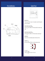
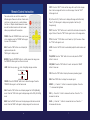
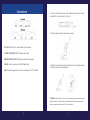
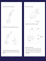
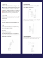
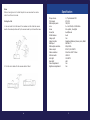
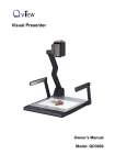
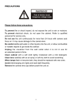
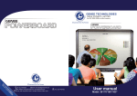
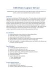
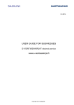
GENEE TECHNOLOGIES
INDIA PRIVATE LIMITED
®
An ISO 9001:2008 certified company
2100
Classroom for the Future
®
2100
Classroom for the Future
Tel: 0124-4934500
@ Email: [email protected]
WWW Website: www.genee-india.com, www.geneeworld.com
Plot No. 698, Udyog Vihar, Phase V, Gurgaon, Haryana-122016, India
Fax: 0124-4934521
User manual
PRECAUTIONS
Contents
Parts Identification ........................................................ ...............4
Control Panel ..............................................................................5
Remote Control Instruction ............................................................6
Connections................................................................................8
Installing the software .................................................................12
Please follow these precautions:
To prevent fire or shock hazard, do not expose the unit to rain or
moisture
To prevent electrical shock, do not open the cabinet, Refer to qualified
personal for service only
Do not use the unit continuously for more then 24 hours with camera
auto focus on. It may cause damage to the camera lens
Be careful not to spill water or other liquids onto the unit, or allow
combustible or metallic objects to get inside the cabinet
Unplug the visualiser from the wall outlet when it is not in use for an
extended period of time
Clean the cabinet with a soft cloth lightly moistened with a mild
detergent
Clean the lens carefully with an air spray or soft dry cloth to avoid
scratching
When lamps flashes or become dark, they should be replaced with
new ones
2
3
Parts Identification
Control Panel
Power button
Press the button once to power on the visualiser; press the button again to
power off the visualiser
Output visualiser signal button
Press the button, the RGB OUTPUT terminal outputs the visualiser signal
Output
Output computer signal button
Press the button, the RGB OUTPUT terminal outputs computer signal
Auto button A
Press the A button to automatically adjust white balance and focus
Light button
Each time you press the
button, the lighting changes as below:
The body lights on
The back light on
All the lights off
Zoom button
Press the or
4
button to zoom in or zoom out
5
Remote Control Instruction
The remote control can control the camera from
different angles. Please note that an infrared remote
control can only be used up to a certain distance
from the unit. Objects situated between the visualiser and the infrared remote control and a weak
battery may interfere with the reception.
POWER: Press the “POWER” button once to power
on the visualiser, press the “POWER” button again
to power off the visualiser
NEG: Press the “NEG” button once to display file
negatives and press the
“NEG” again to display normal
MIRROR: Press the “MIRROR” button to vertically reverse the image; press
the “MIRROR” button again to exit the mirror mode
LAMP: Each time you press
button, the lighting changes as below:
The body lights on
The back light on
All the lights off
FREEZE: Press the “FREEZE” button once to freeze the image. Press the
“FREEZE” button again to exit the freeze mode
XGA: Press the “XGA” button once to display images from SVGA (800x600)
mode. Press the “XGA” button again to display images at the XGA (1024x786)
mode
B&W: Press the “B&W” button once to display images at the black and white
mode. Press the “B&W” button again to display images at the colour mode
6
SPLIT: Press the “SPLIT” button and the image will be split into two images.
One is the live image and the other is a frozen image. Press the “SPLIT”
button again to exit
D./S: Press the “D./S” button once to display still images with better clarity.
Press “D./S” button again to display moving objects at real time (30
frame/second)
TEXT: Press the “TEXT” button once to switch to the text mode to sharpen the
edge of the text. Press the “TEXT” button again to return to the image mode
TITLE: Press the “TITLE” button once to freeze top 1/8 of the screen. Press
the “TITLE” button again to exit
AUTO: Press the “AUTO” button to automatically adjust the white balance and
focus
TELE/WIDE: Press the “TELE” button to zoom in and press the “WIDE”
button to zoom out
FAR/NEAR: Press the “FAR” button to focus far and press the “NEAR”
button to focus near
CDD: Press the “CDD” button to display the camera (visualiser) signal
RGB: Press “RGB” button to display the computer signal
BRIGHT +/-: Press the “+” button to increase the brightness. Press the
“-” to decrease the brightness
RED +/-: Press the “+” button to increase the red hue. Press the “-” to
decrease the red hue
BLUE +/-: Press the “+” button to increase the blue hue. Press the “-”
to decrease the blue hue
7
Connections
1. Use one hand to hold the base of the visualiser and use the other hand
to carefully lift up the mirror stand of the unit
2. Place the camera stand to the maximum position
DC-12V IN: External 12V power adaptor input connection
S-VIDEO-OUT/VIDEO-OUT: Visualiser video output
RGB-OUT1/RGB-OUT2: RGB output (output the same signal)
RGB-IN: Laptop, computer or other RGB signal input
USB: Computer image capture and video recording for both PC and MAC
3. Rotate the camera head, make sure that mark E on the Camera head is
in line with mark B on the camera stand
ATTENTION: When mark E is in line with A, the camera head and the base are parallel. When mark E is in line with mark D, the camera head and the base are vertical.
When the visualiser is folded, mark E is in line with mark C
8
9
4. Place the mirror stand to the maximum position
Step 1: Connect to the computer
Step 2: Connect to the projector and video equipment
5. Rotate the mirror to the position so that the two mark lines line up
6. Making connections Before making any connections, turn off all the
power. Please ensure that the visualiser along with all other equipment is
turned off.
10
Step 3: Connect to power source
Once the visualiser is set up, plug in the power adaptor that comes
with your visualiser into the DC 12V IN connector and an external
power source. Press the power button on the operating panel to turn
on the visualiser
11
Installing the Software
The function of the Video Cap software is to snap and display images with the
USB interface, which includes displaying static and dynamic pictures, snapping
dynamic images and playback the dynamic images with the Windows Media
Player or similar player.
A. Insert the CD-ROM that comes with your visualiser into the CD-ROM drive.
if Auto run is enabled on your system, then the Software Setup window will be
displayed automatically as below.
If it does not start automatically, after inserting the CD-ROM, click [Start] ->
[My Computer], and then double click ( the CD-ROM drive letter might be
different in different computer systems) and then the above screen will appear
immediately
B. Click the Install DirectX9.0 button to install Microsoft DirectX9.0
C. Click the Install Capture Program button to install the program that captures
images in the AVI or Bitmap format
D. Click the Install USB Driver button to install the driver designed for the visualiser and will be used by the Capture Program
E. After the installation is finished, then click the Exit button to exit the Software Setup Window
F. Shut down your computer when prompted in order for the changes to take
effect
G. Use the USB2.0 cable provided to connect your computer to the visualiser
before your computer is restarted
H. Turn on the visualiser
Remarks: DirectX9.0 is not necessary to install, it is mainly for computer print
screen function
Please pay attention to the following:
1. Computer hardware requirements; CPU: Pentium 4 2.0G or above, RAM:
256M or above, USB 2.0 port, Hard disk 40G or more
2. Operating system: Windows 2000 or above. If the operating system is
Windows 2000, should install SP4. If the operating system is Windows XP, you
should install SP11. 12V IN: External 12V power adaptor input connection
S-VIDEO-OUT/VIDEO-OUT: Visualiser video output
12
3. You must use the high speed USB cable provided
4. When connecting the visualiser to a desktop computer using the high
speed USB cable provided, we recommend using the USB port located
on the rear of the mainframe. The USB port on the front of the computer
might have interference.
5. You may need to install the USB driver again when you change a
computers USB port. If this port has USB 2.0 driver installed, there is no
need to install the USB driver again
6. If you cannot capture images under the Video Capture program, you
need to set the signal input source as follows: click “Option” - “Video
crossbar”, and then set INPUT as Video Composite In.
USB capture for MAC computers:
Copy the folder “Mac Driver” into MAC hard disk, open the folder and double
click “Empia 1.0.0b2.zip”, the “setup” file appears. Following the screen
notice, click “Next” and finish installation.
Notes
1. Please connect the MAC computer and visualiser when installing the
driver
2. Please use the USB 2.0 cable provided with your visualiser
Video display and capture:
You can capture and control images on the visualiser from a computer
connected with a USB connector
Click [Start] - [Program] - [VideoCap] - “VideoCapx.xx” (x.xx is softwares
version) to open the software
A. Static Image Setup
Click “Capture” - “Capture Frame”, input the file name in dialogue box, or
you can click icon on the
toolbar, then input file name in dialogue window.
The image file is JPG format
13
B. Snap Video Stream
Click “Capture” - “Start Capture”, input the file name in dialogue box, or click
icon on the toolbar, then input the file name in dia-logue box. If you want
to set the time limit for the capture, select “Capture” - “set Time Limit” to set
the time limit. Click “Start Capture” to start capture, and click “Stop Capture” or
icon on the toolbar to stop capture. (If you have set the time limit, it will
stop automatically when the time is set up.) The video file is AVI format.
C. Set the Frame Rate
Click [Capture] - [Set Frame Rate], and then click open “Choose Frame Rate”
to set the frame rate.
D. Set Time Limit
Click [Capture] - [Set Time Limit] to set the time limit while capturing video.
Wall mounting applications
Install visualiser on the wall and position the camera head parallel to
the base. (Need take close-up lens off first)
Install visualiser on the wall and position the camera head vertically to the
base. (Need to take close-up lens off first)
E. Note
Do Not connect/disconnect the USB cable when the application is running,
which will cause the program to be interrupted.
Other applications
Displaying standard slides and negatives
Insert a standard slide or negative to the slot on the mirror, flip the mirror to
the position that the slide or negative faces the camera head, then turn on the
back light to display the slide or negative.
14
Ceiling mounting applications
Attach the wall installation base to the base of the visualiser, screw down the
four screws to fix the base and then mount the visualiser to the ceiling.
15
Notes
When not using the mirror to reflect objects, the user must use the remote
control to exit the mirror mode.
Folding the Unit
1. Use one hand to hold the base of the visualiser and the rotate the camera
head to the marked position and flip the camera head to point toward the base
2. Fold the mirror stand after the camera stand is folded
16
Specification
Pickup device
Total pixels
RGB output pixels
Lens
Focus
Focus/Iris
White balance
Image split
Image function
RGB input
RGB output resolution
Video output
Video resolution
USB connector
Arm light
Back light
Colour adjustment
Brightness adjustment
1/4” professional CCD
470,000
780,000
F=1.6-3.7mm/f=3.9-85.8mm
22x optical, 10x digital
Auto/Manual
Auto
Yes
Negatives/Positives, freeze, mirror, B&W
DB15FLC*1
XGA, SVGA
RCA*1, Min DIN4*1
More than 480 TV lines
USB 2.0
1W LED*2
LED
Yes
Yes
17