1
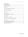
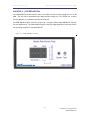
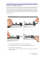
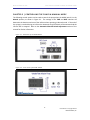
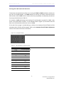
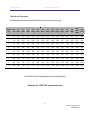
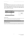
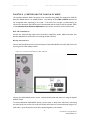
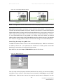
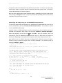
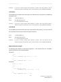
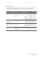
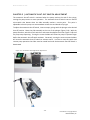
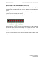
instrumentation and software for research
VARIABLE SPEED INFUSION PUMP
WITH SERIAL CONTROL
PHM-100VSS
USER’S MANUAL
DOC-001
Rev. 3.5
Copyright ©2013
All Rights Reserved
Med Associates Inc.
P.O. Box 319
St. Albans, Vermont 05478
Phone: 802.527.2343
Fax: 802.527.5095
www.med-associates.com
PHM-100VSS VARIABLE SPEED INFUSION PUMP
notes
-iDOC-001 Rev 3.5 Copyright © 2013
MED Associates, Inc.
PHM-100VSS VARIABLE SPEED INFUSION PUMP
Table of Contents
Chapter 1 | Introduction ........................................................................................................ 1
Chapter 2 | Syringe Placement ............................................................................................... 2
Priming the Line............................................................................................................................... 3
Glass Syringes .................................................................................................................................. 3
Chapter 3 | Controlling the Pump in Manual Mode ................................................................. 4
Setting the TIME and RATE Switches............................................................................................... 5
Flow Rates and Pump Speeds.......................................................................................................... 7
MED Control .................................................................................................................................... 8
TTL Control (5V) ............................................................................................................................... 8
Switch Closure Control .................................................................................................................... 8
Chapter 4 | Controlling the Pump in PC Mode ......................................................................... 9
DIG-729 Installation ......................................................................................................................... 9
Wiring Instructions .......................................................................................................................... 9
Controlling the Pump Using MED Test .......................................................................................... 10
Controlling the Pump Using the Included MED-State Notation .................................................... 11
Controlling the Pump Using Custom MED-State Notation............................................................ 12
MED-PC Log Errors ........................................................................................................................ 14
Chapter 5 | Automatic Shut-Off Switch Adjustment .............................................................. 15
Appendix A | PHM-100VSS Addressing Scheme .................................................................... 16
Appendix B | Contact Information ........................................................................................ 17
- ii DOC-001 Rev 3.5 Copyright © 2013
MED Associates, Inc.
MED ASSOCIATES INC.
P H M - 1 0 0 V SS V AR I A B L E S P E E D I NF U SI O N P U M P
CHAPTER 1 | INTRODUCTION
The PHM-100VSS provides infusions from 0.1 to 99.9 seconds at rates ranging from 0.5 to 20
RPM. The unit can be operated using a MED interface output bit, a TTL control line, a switch
closure, MED-PC, or a computer with the serial control.
The PHM-100VSS requires 110 volts, 60 cycle AC. Use part number PHM-100VSSA for 220 volt,
50 cycle applications. The PHM-100VSS requires a DIG-729 High Speed Serial controller card in
the operating computer if used with MED-PC.
Figure 1-1 – PHM-100VSS Front View
-1DOC-001 Rev 3.5 Copyright © 2013
MED Associates, Inc.
MED ASSOCIATES INC.
P H M - 1 0 0 V SS V AR I A B L E S P E E D I NF U SI O N P U M P
CHAPTER 2 | SYRINGE PLACEMENT
Care should be exercised to ensure that the hub of the syringe barrel is positioned adjacent to
the syringe clamp when loading the syringe pump. If a gap exists between the hub and the
clamp, accurate flow rates cannot be assured, as the entire syringe (both barrel and plunger)
may move forward. A visual check by observing the plunger move in relation to the barrel by
rotating the front knob of the pump is advised. Figure 2-1 illustrates the procedure for loading a
syringe into the pump.
Figure 2-1 - Loading a Syringe
1. Move the slide to rear (toward motor section) by squeezing the jaws.
2. Insert syringe by lifting clamp cover and placing the syringe body into the clamp.
3. Move the slide to the end of the syringe.
4. Rotate the knob so that the slide makes contact with the plunger and the syringe
contacts the clamp.
-2DOC-001 Rev 3.5 Copyright © 2013
MED Associates, Inc.
MED ASSOCIATES INC.
P H M - 1 0 0 V SS V AR I A B L E S P E E D I NF U SI O N P U M P
Priming the Li ne
Once the syringe is installed, the line should be primed until liquid drips out of the syringe or
tubing. This ensures that fluid will be infused properly when the pump is activated.
Prime the line by setting the Flush switch in the “down” position for as long as required. The
settings of the TIME and RATE switches are not recognized when the Flush switch is on; the
pump will operate at 10 RPM and will only operate when a timed infusion is not in progress.
Glass Syringes
Extra caution should be exercised when using glass syringes with a ground glass plunger. These
syringes exhibit almost no sliding friction and thus can cause an uncontrolled infusion in the
following two ways:
1. The weight of the plunger may be sufficient to push the fluid out of the syringe if the syringe
is held with the plunger above the syringe.
2. The weight of the fluid in the tubing may be sufficient to siphon the fluid out of the syringe if
the catheter infusion site is below the height of the syringe.
3. To test for these two conditions, it is suggested that the syringe be connected to the tubing
and held vertically at the height of the pump. If no motion occurs, the syringe can then be
placed in the pump.
The following may reduce the danger of an uncontrolled infusion:
1. Lower the relative height of the infusion pump in relation to the infusion site. With the
pump below the infusion site, the instrument will pump the fluid to the higher elevation.
2. Use a smaller bore catheter, which will reduce the weight of the fluid in the tubing and
increase the friction on the flowing fluid.
3. Position the pump so that the syringe is vertical (plunger below), thus the weight of the
syringe plunger will be acting against the weight of the fluid.
Use a syringe with a rubber seal on the plunger, i.e. an O-ring sealed or plastic syringe.
-3DOC-001 Rev 3.5 Copyright © 2013
MED Associates, Inc.
MED ASSOCIATES INC.
P H M - 1 0 0 V SS V AR I A B L E S P E E D I NF U SI O N P U M P
CHAPTER 3 | CONTROLLING THE PUMP IN MANUAL MODE
The following control options can be used to control the pump when the MODE switch is in the
Manual position, as shown in Figure 3-1. The settings of the TIME and RATE switches will
determine the duration and rate of the infusion when operating in Manual mode. If the end of
the syringe is reached during an infusion the Automatic Shut-Off Switch will be activated and the
infusion will be stopped. Refer to the Automatic Shut-Off Switch Adjustment section of this
manual for further information.
Figure 3-1 - Back Panel of the PHM-100VSS
Figure 3-2 - Front Panel of the PHM-100VSS
-4DOC-001 Rev 3.5 Copyright © 2013
MED Associates, Inc.
MED ASSOCIATES INC.
P H M - 1 0 0 V SS V AR I A B L E S P E E D I NF U SI O N P U M P
Setti ng the TIME and RATE Switches
The duration and speed of the infusion are set using the TIME and RATE pushbutton switches on
the front of the PHM-100VSS. The TIME switches are used to set infusion times from 00.0 to
99.9 seconds, and the RATE switch is used to select the pump RPMs, as indicated by the table on
the pump, and also shown in Table 3.1.
For example, a RATE pushbutton switch setting of 2 would produce a speed of 1.0 RPM. Note
that 0 is not used and has no effect. In the example shown in Figure 3-3, the infusion time has
been set to 35.0 seconds and the rate is set to 2.0 RPM.
If the end of the syringe is reached during an infusion the Automatic Shut-Off Switch will be
activated and the infusion will be stopped. Refer to the Automatic Shut-Off Switch Adjustment
section of this manual for further information.
Figure 3-3 - Example Settings
Table 3.1 - RATE Pushbutton Switch Settings
RATE Pushbutton
Setting
Corresponding RPMs
0
N/A
1
0.5
2
1.0
3
1.5
4
2.0
5
3.33
6
5.0
7
10.0
8
15.0
9
20.0
-5DOC-001 Rev 3.5 Copyright © 2013
MED Associates, Inc.
MED ASSOCIATES INC.
P H M - 1 0 0 V SS V AR I A B L E S P E E D I NF U SI O N P U M P
-6DOC-001 Rev 3.5 Copyright © 2013
MED Associates, Inc.
MED ASSOCIATES INC.
P H M - 1 0 0 V SS SY R I N G E P U M P
Flow Rates and Pump Speeds
The following table shows the flow rates in milliliters per minute of several commonly used syringes.
Thumbwheel
Setting
Motor
RPM
1 mL
Multifit
2 mL
Multifit
5 mL
Multifit
10 mL
Plastipak
10 mL
Multifit
12 mL
Monoject
20 mL
Plastipak
20 mL
Multifit
20 mL
Monoject
30 mL
Plastipak
30 mL
Multifit
35 mL
Monoject
50-60 mL
Plastipak
Monoject
50 mL
Multifit
1
0.50
0.017
0.061
0.106
0.160
0.165
0.193
0.278
0.295
0.323
0.358
0.395
0.437
0.542
0.603
2
1.00
0.034
0.122
0.212
0.320
0.331
0.386
0.557
0.589
0.646
0.715
0.791
0.874
1.084
1.206
3
1.50
0.052
0.184
0.318
0.480
0.496
0.579
0.835
0.884
0.969
1.073
1.186
1.311
1.626
1.809
4
2.00
0.069
0.245
0.424
0.640
0.661
0.773
1.114
1.179
1.292
1.431
1.581
1.748
2.169
2.412
5
3.33
0.115
0.408
0.706
1.066
1.102
1.288
1.856
1.965
2.154
2.385
2.636
2.914
3.614
4.02
6
5.00
0.172
0.612
1.059
1.600
1.653
1.931
2.784
2.947
3.231
3.577
3.954
4.371
5.421
6.031
7
10.00
0.344
1.223
2.118
3.198
3.306
3.863
5.895
5.895
6.462
7.155
7.907
8.741
10.843
12.061
8
15.00
0.516
1.835
3.177
4.798
4.959
5.794
8.353
8.843
9.694
10.732
11.861
13.112
16.264
18.092
9
20.00
0.688
2.446
4.236
6.397
6.612
7.726
11.137
11.789
12.925
14.310
15.814
17.483
21.686
24.122
To calculate the flow rate of a syringe not given above, use the following formula:
Flow Rate (mL/min) = 0.19538 * RPM * syringe cross-sectional area
-7DOC-001 Rev 3.5 Copyright © 2013
MED Associates, Inc.
MED ASSOCIATES INC.
P H M - 1 0 0 V SS V AR I A B L E S P E E D I NF U SI O N P U M P
MED Control
Connect the MED Control connector shown in Figure 3-1 to any available output on a Standard
MED Connection Panel using a standard Molex cable. The pinout of the 3-pin Molex connector
is shown in Figure 3-4. Upon receiving an operate signal, the pump will begin the infusion the
settings of the TIME and RATE switches on the front panel, and then it will stop. The operate
signal must be toggled off between infusions. Any changes made to the TIME and RATE settings
during an infusion will not be acknowledged.
Figure 3-4 - MED Control Connector Pinout
Molex Pin #
Function
1
Not Used
2
+28 Volts
3
Operate
TTL Control (5V)
Connect the TTL ground to the (-) screw terminal and the TTL operate signal to the (+) screw
terminal. A TTL high to low transition on the operate line activates the pump.
CAUTION: Voltage levels above 5.2 VDC at the TTL terminals can damage the unit.
Switch Closur e Control
Simply connect a switch between the (+) and (-) screw terminals. Closing the switch will operate
the pump. The switch must be opened and closed again to activate the pump for another cycle.
-8DOC-001 Rev 3.5 Copyright © 2013
MED Associates, Inc.
MED ASSOCIATES INC.
P H M - 1 0 0 V SS V AR I A B L E S P E E D I NF U SI O N P U M P
CHAPTER 4 | CONTROLLING THE PUMP IN PC MODE
The supplied software allows the pump to be controlled using MED Test program or MED-PC
when the MODE switch is in the PC position. The settings of the TIME and RATE switches are
not recognized when operating in PC mode. If the end of the syringe is reached during an
infusion the Automatic Shut-Off Switch will be activated and the infusion will be stopped. Refer
to the Automatic Shut-Off Switch Adjustment section of this manual for further information.
DIG-729 Installation
Consult the “DIG-729 High Speed Serial Controller Installation Guide” (MED Associates Part
Number DOC-002) for instructions on installing the DIG-729 card.
Wiring Instructions
Connect the female DB-15 port on the back panel of the PHM-100VSS to the DIG-729 card in the
PC using the SG-219C cable provided.
Figure 4-1 – Connect Female DB-15 to DIG-729 Card
Connect the PHM-100VSS power cord to a standard wall outlet and power on using the lighted
ON/OFF switch.
To control additional PHM-100VSS pumps, connect them in daisy-chain fashion by connecting
the male DB-15 port on the first pump the female DB-15 port on the second pump using an SG219C cable. Up to 16 pumps may be daisy chained together in this fashion.
-9DOC-001 Rev 3.5 Copyright © 2013
MED Associates, Inc.
MED ASSOCIATES INC.
P H M - 1 0 0 V SS V AR I A B L E S P E E D I NF U SI O N P U M P
Figure 4-2 – Controlling Additional Pumps
NOTE: The length of the SG-219C cables used to connect the pumps should not exceed 10-feet.
PHM-100VSS node numbers are factory set and should be clearly labeled on the pump case.
The units can be daisy-chained in any order; however, the last unit in a series must have the
highest node number and must have the terminate switches ON. In most cases, users will not
need to adjust the network address or terminate settings on the PHM-100VSS pump. However,
if a new PHM-100VSS pump is being added to an existing daisy-chain network, the network
address and terminate settings of the PHM-100VSS pumps may need to be reset. See Appendix
A for details on changing network addresses and terminate settings on the PHM-100VSS pump.
Contr olling the Pump Using MED Test
The MED Test software allows the user to test the PHM-100VSS pumps. MED Test is included on
the MED-PC software CD. If an updated version of MED Test is needed, please contact MED
Associates for instructions on how to get the latest version.
Open MED Test and select Pumps | PHM-100VSS to open the Test Screen.
Figure 4-3 - MED Test Screen
Enter the node number (the pump should be labeled with this number), the desired rate (RPM),
and Infusion Time in seconds. Once these values are entered, click Set Pump to start the PHM100VSS pump. After the data is sent to the pump the pump's status is displayed in the Sum
- 10 DOC-001 Rev 3.5 Copyright © 2013
MED Associates, Inc.
MED ASSOCIATES INC.
P H M - 1 0 0 V SS V AR I A B L E S P E E D I NF U SI O N P U M P
Check Sent and Sum Check Rec fields. The two fields should match. If a pump is not responding,
check that the power is on and all network connections have been properly made. If necessary,
contact MED Associates for further assistance.
Once the correct data has been entered and the pump is responding, the pump can be turned
on by clicking the Pump On button. A pump may be operated repeatedly with the same data by
repeatedly clicking the Pump On button.
Contr olling the Pump Using the Included MED -State Notation
To control the pump using the program that is included on the PHM-100VSS CD, insert the CD
into the CD-ROM drive and click To Install the PHM-100VSS Software. The procedure is copied
into the installation directory.
Programs written in MedState Notation must be translated using Trans IV before they can be
executed in this application. Open Trans IV icon and select Translation | Translate and Compile.
Select the program(s) to use and click Make. Click OK to start the translator, and it will
automatically parse the MedState Notation and then open to a DOS screen to compile the
Pascal code. Depending on the speed of the computer, each of these steps may not be seen.
Open MED-PC and the MED-PC Experiment Loading Wizard’s Welcome screen will appear.
Follow the steps to load the program, issue a START command or the desired K-pulse by
selecting to Configure | Signals.
\ Copyright (C) 2008 MED Associates, All rights reserved.
\
\
\
\
\
\
\
\
\
PHM100VSS.MPC
This program demonstrates how to properly call the MED-PC commands that Start
and Stop the PHM-100VSS Pump.
The BOX parameter specifies which PHM-100VSS Pump to start. When this program
is running in Box 1, then the BOX parameter will equal 1 and Pump 1 will
start. When this program is running in Box 2, then the BOX parameter will
equal 2 and Pump 2 will start, etc. This allows the same program to be run in
multiple Boxes and control different Pumps.
\ A() = Control Variables with Assigned Aliases as Defined
Var_Alias Duration (0.1 - 99.9 seconds) = D \ Default = 10 seconds
Var_Alias Rate (0.5 - 20.0 RPM)
= R \ Default = 1 Revolution Per Minute
\ List Working Variables Here
\ E = Infusion Duration in MED Ticks
\ K-Pulses Used in this Program
\ K1 = Turn on the Pump at the currently set Rate and then increase the Rate by 1
\ K2 = Turn on the Pump at the currently set Rate and then decrease the Rate by 1
\ K3 = Lock on the Pump at the currently set Rate
\ K4 = Turn off the Pump
S.S.1,
S1,
0.001": SET D = 10, R = 1 ---> S2
S2,
#START: ---> S3
1": SHOW 1,Duration,D, 2,Rate,R ---> S2
- 11 DOC-001 Rev 3.5 Copyright © 2013
MED Associates, Inc.
MED ASSOCIATES INC.
P H M - 1 0 0 V SS V AR I A B L E S P E E D I NF U SI O N P U M P
S3,
\ Send the values down to the Pump
0.01": ~SetPump(MG, BOX, R, D);~;
SHOW 1,Duration,D, 2,Rate,R, 3,Pump Off,0;
SET E = D * 1" ---> S4
S4,
\ Wait for command to turn the Pump on
#K1: ~OnPump(MG, BOX);~; SET R = R + 1;
SHOW 3,Pump On,1 ---> S5
#K2: ~OnPump(MG, BOX);~; SET R = R - 1;
SHOW 3,Pump On,1 ---> S5
#K3: ~LockOnPump(MG, BOX);~;
SHOW 3,Pump On,1 ---> S6
S5,
\ Make sure the User can't send another OnPump
\ command while the Pump is running.
E#T: IF R > 20 [@True, @False]
@True: SET R = 20 ---> S3
@False: IF R < 1 [@True, @False]
@True: SET R = 1 ---> S3
@False: ---> S3
S6,
\ Turn the Pump off
#K4: ~LockOffPump(MG, BOX);~ ---> S3
Contr olling the Pump Using Custom MED -State N otati on
The PHM-100VSS can be controlled using the included MED-State Notation procedure (PHM100VSS.mpc), or a custom procedure can be created using the following commands.
SetPump
The SETPUMP command sets all pump parameters to be the same as the specified pump and
retains them until they are changed or power is turned off.
Syntax:
~SetPump(MG, P1, P2, P3);~
Where:
MG = MED-PC Global Pointer
P1 = The Pump Node Value (1 to 16)
P2 = The Rate (0.5 to 20 RPM)
P3 = The Infusion Time (0.1 to 99.9 seconds)
Comments:
P1 through P3 may be numbers, constants, special identifiers, or variables. Note: Array elements
must be expressed using square brackets P[1], not the normal parenthesis ( ) used in MEDSTATE
NOTATION.
OnPump
The ONPUMP command selects the pump node and turns that pump on. It is not necessary to
issue a SETPUMP command each time the pump is turned on. Allow at least one clock tick
between the SETPUMP command and the ONPUMP command; i.e., do not place both
commands in the same State.
Syntax:
~OnPump(MG, P1);~
Where:
MG = MED-PC Global Pointer
P1 = The Pump Node Value (1 to 16)
- 12 DOC-001 Rev 3.5 Copyright © 2013
MED Associates, Inc.
MED ASSOCIATES INC.
Comments:
P H M - 1 0 0 V SS V AR I A B L E S P E E D I NF U SI O N P U M P
P1 may be a number, constant, special identifier, or variable. Note: Array elements must be
expressed using square brackets P[1], not the normal parenthesis ( ) used in MEDSTATE NOTATION.
LockOnPump
The LockOnPump command selects the pump node and locks on the pump until a LockOffPump
command is sent.
Syntax:
~LockOnPump(MG, P1);~
Where:
MG = MED-PC Global Pointer
P1 = The Pump Node Value (1 to 16)
Comments:
P1 may be a number, constant, special identifier, or variable. Note: Array elements must be
expressed using square brackets P[1], not the normal parenthesis ( ) used in MEDSTATE NOTATION.
LockOffPump
The LockOffPump command selects the pump node and turns off the pump. It can even turn off
the pump when it was turned on with the PumpOn command.
Syntax:
~LockOffPump(MG, P1);~
Where:
MG = MED-PC Global Pointer
P1 = The Pump Node Value (1 to 16)
Comments:
P1 may be a number, constant, special identifier, or variable. Note: Array elements must be
expressed using square brackets P[1], not the normal parenthesis ( ) used in MEDSTATE NOTATION.
MedState Notation Examples
The following two examples are functionally equivalent. A five second infusion at 3.33 RPM is
used as the reinforcer for an FR-10 schedule.
Example A:
S.S.1,
S1,
0.01": ~SETPUMP(MG, BOX, 3.33, 5);~ ---> S2
S2,
10#R1: ~ONPUMP(MG, BOX);~ ---> S2
Example B:
LIST P = 0, 3.33, 5
S.S.1,
S1,
0.01": SET P(0) = BOX;
~SETPUMP(MG, P[0], P[1], P[2]);~ ---> S2
S2,
10#R1: ~ONPUMP(MG, P[0]);~ ---> S2
- 13 DOC-001 Rev 3.5 Copyright © 2013
MED Associates, Inc.
MED ASSOCIATES INC.
P H M - 1 0 0 V SS V AR I A B L E S P E E D I NF U SI O N P U M P
MED-PC Log Errors
If a pump parameter is improperly specified or a pump is not responding, MED-PC will flag the
error in the log files. The following list describes the errors and how to correct them:
Error
[1]
Pump is not responding
[2]
Rate must be between 0.5
and 20 RPM
[3]
Duration must be 0.1 to 99.9
seconds.
[4]
Pump halted due to errors
Cause
Correction
The pump specified by SETPUMP
did not return the proper
checksum within the time
required.
Check that a pump with that number exists
in the system. Verify that the unit's power
is on. Check all network cabling. Refer to
page
1
for
electrical
connection
information. Try operating the unit using
the MED Test program.
Call MED
Associates for assistance if necessary.
Rate is not set within the
allowable range.
Verify that the proper rates are used. Refer
to the Controlling the Pump Using Custom
MED-State Notation section of this manual.
Duration is not set within the
allowable range.
Verify that the proper durations are used.
Refer to the Controlling the Pump Using
Custom MED-State Notation section of this
manual.
ONPUMP command not allowed
due to errors in a previous
SETPUMP command.
Check the log for previous errors and refer
to the listings above for explanations.
- 14 DOC-001 Rev 3.5 Copyright © 2013
MED Associates, Inc.
MED ASSOCIATES INC.
P H M - 1 0 0 V SS V AR I A B L E S P E E D I NF U SI O N P U M P
CHAPTER 5 | AUTOMATIC SHUT-OFF SWITCH ADJUSTMEN T
The automatic shut-off switch is activated when the pump reaches the end of the syringe,
causing the pump motor to cease operation. The automatic shut-off switch uses an internal
micro-switch that detects when the slide assembly reaches a certain point. This point is
adjustable so that the pump can accommodate various sizes and brands of syringes.
To adjust the automatic shut-off switch, insert an empty syringe with the plunger at the desired
shut-off position. Move the slide assembly to the rear of the plunger (Figure 5-1A). With the
pump turned on, switch the Flush switch on and rotate the adjustment screw (Figure 5-1B) until
the pump stops operating. Turning the screw clockwise will allow the pump to operate longer
before the automatic shut-off switch activates. Conversely, turning the screw counterclockwise
will cause the automatic shut-off switch to activate sooner. In order to reset this switch and
resume pump operation the slider must be moved back until the Automatic Shut-Off Switch is
deactivated.
Figure 5-1 – Automatic Shut-Off Switch Adjustment
- 15 DOC-001 Rev 3.5 Copyright © 2013
MED Associates, Inc.
MED ASSOCIATES INC.
P H M - 1 0 0 V SS V AR I A B L E S P E E D I NF U SI O N P U M P
APPENDIX A | PHM-100VSS ADDRESSING SCHEME
The PHM-100VSS pump address settings should only be modified if a new pump is being added
to an existing network. If the pumps have been purchased from MED Associates as part of a
package or system, the addresses have been factory set and there is no need to adjust these
settings.
To change the address or termination settings of a PHM-100VSS pump, remove the two
recessed screws from the bottom panel of the unit.
There is an 8-position dipswitch that resembles Figure 5-2.
Figure 5-2 - PHM-100VSS Dipswitch
Switches 1 through 4 are used for setting the pump’s address according to Table 5.1. Switches
6, 7, and 8 are used for differential line terminations, which are preset at the factory. Do not
change unless adding additional pumps to the configuration. Only the last pump in the series
should have switches 6, 7, and 8 set to ON. All other pumps should have these switches set to
OFF. Switch 5 is not used.
In Figure 5-2 the pump address is set to 1 and since the terminate switches are all ON, it is the
last pump in the series.
- 16 DOC-001 Rev 3.5 Copyright © 2013
MED Associates, Inc.
MED ASSOCIATES INC.
P H M - 1 0 0 V SS V AR I A B L E S P E E D I NF U SI O N P U M P
Table 5.1 - Address Switch Positions
Switch Number
Pump
Address
1
2
3
4
1
OFF
ON
ON
ON
2
ON
OFF
ON
ON
3
OFF
OFF
ON
ON
4
ON
ON
OFF
ON
5
OFF
ON
OFF
ON
6
ON
OFF
OFF
ON
7
OFF
OFF
OFF
ON
8
ON
ON
ON
OFF
9
OFF
ON
ON
OFF
10
ON
OFF
ON
OFF
11
OFF
OFF
ON
OFF
12
ON
ON
OFF
OFF
13
OFF
ON
OFF
OFF
14
ON
OFF
OFF
OFF
15
OFF
OFF
OFF
OFF
16
ON
ON
ON
ON
APPENDIX B | CONTACT INFORMATION
Please contact MED Associates, Inc. for information regarding any of our products.
Visit our website at www.med-associates.com for contact information.
For technical questions, email [email protected].
- 17 DOC-001 Rev 3.5 Copyright © 2013
MED Associates, Inc.