1
Drive Technology \ Drive Automation \ System Integration \ Services
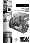
Drive System for Decentralized Installation
InterBus Interfaces, Field Distributors
Edition 11/2008
16727215 / EN
Manual
SEW-EURODRIVE – Driving the world
Contents
Contents
1
Valid Components............................................................................................... 6
2
General Information ............................................................................................ 7
3
2.1
How to use the operating instructions ......................................................... 7
2.2
Structure of the safety notes ....................................................................... 7
2.3
Rights to claim under limited warranty ........................................................ 8
2.4
Exclusion of liability..................................................................................... 8
2.5
Copyright..................................................................................................... 8
Safety Notes ........................................................................................................ 9
3.1
General ....................................................................................................... 9
3.2
Target group ............................................................................................... 9
3.3
Designated use ........................................................................................... 9
3.4
Other applicable documentation ............................................................... 10
3.5
Transportation, storage ............................................................................. 10
3.6
Installation ................................................................................................. 10
3.7
Electrical Connection ................................................................................ 11
3.8
Safe disconnection.................................................................................... 11
3.9
Operation .................................................................................................. 11
3.10 Supplementary safety notes for field distributors ...................................... 13
4
5
6
Unit Design ........................................................................................................ 14
4.1
Fieldbus interfaces .................................................................................... 14
4.2
INTERBUS interfaces – unit designation .................................................. 17
4.3
Field distributors........................................................................................ 18
4.4
INTERBUS field distributors – unit designation ........................................ 22
Mechanical Installation..................................................................................... 24
5.1
Installation instructions.............................................................................. 24
5.2
Tightening torques .................................................................................... 25
5.3
MF.. / MQ.. fieldbus interfaces .................................................................. 28
5.4
Field distributors........................................................................................ 31
Electrical Installation ........................................................................................ 36
6.1
Installation planning considering EMC aspects ........................................ 36
6.2
Installation instructions for fieldbus interfaces/field distributors ................ 38
6.3
Connection with INTERBUS (copper line) ................................................ 44
6.4
Connecting INTERBUS with fiber-optic cable ........................................... 57
6.5
Connection of MF../MQ.. fieldbus interface inputs/outputs (I/O) ............... 64
6.6
NV26 proximity sensor connection ........................................................... 68
6.7
Connection of ES16 incremental encoder ................................................ 70
6.8
Connection of EI76 incremental encoder .................................................. 72
6.9
Hybrid cable connection............................................................................ 76
6.10 Keypad connection ................................................................................... 78
6.11 PC connection........................................................................................... 80
Manual – InterBus Interfaces, Field Distributors
3
Contents
7
8
9
10
Startup with MFI.. INTERBUS Interface (Copper Line) .................................. 81
7.1
Startup procedure ..................................................................................... 81
7.2
MFI DIP switch settings ............................................................................ 84
7.3
Configuring (projecting) the INTERBUS master) ...................................... 86
7.4
Creating the process data description ...................................................... 87
Function of the MFI INTERBUS Interface (Copper Line) ............................... 90
8.1
Process data and sensor/actuator processing .......................................... 90
8.2
Structure of the MFI input/output word...................................................... 91
8.3
Meaning of the LED display ...................................................................... 92
8.4
MFI system fault/MOVIMOT® fault............................................................ 94
8.5
Diagnostics via INTERBUS master interface module (G4) ....................... 95
8.6
Process data monitoring ........................................................................... 96
Startup with MFI.. INTERBUS Interface (Fibre Optic Cable).......................... 97
9.1
Startup procedure ..................................................................................... 97
9.2
DIP switch settings.................................................................................. 100
9.3
Configuring (projecting) the INTERBUS master ..................................... 101
9.4
Creating the process data description .................................................... 102
Function of the MFI INTERBUS Interface (Fibre Optic Cable) .................... 105
10.1 Process data and sensor/actuator processing ........................................ 105
10.2 Structure of the MFI23/MFI33 input/output word .................................... 106
10.3 INTERBUS peripheral fault ..................................................................... 107
10.4 Meaning of the LED display .................................................................... 107
10.5 MFI system fault/MOVIMOT® fault.......................................................... 110
10.6 Diagnostics via INTERBUS master interface module (G4) ..................... 111
10.7 Process data monitoring ......................................................................... 112
11
Startup with MQI.. INTERBUS Interface (Copper Line) ................................ 113
11.1 Startup procedure ................................................................................... 113
11.2 MQI DIP switch settings.......................................................................... 116
11.3 Configuring the INTERBUS master ........................................................ 118
11.4 Creating the process data description .................................................... 119
12
Function of the MQI INTERBUS Interfaces (Copper Line)........................... 120
12.1 Default program ...................................................................................... 120
12.2 Control via INTERBUS............................................................................ 121
12.3 PCP interface.......................................................................................... 121
12.4 Return codes of the parameterization ..................................................... 132
12.5 INTERBUS peripheral fault ..................................................................... 134
12.6 Meaning of the LED display .................................................................... 135
12.7 Error states ............................................................................................. 137
13
Supplementary Field Distributor Startup Information ................................. 138
13.1 MF../Z.6., MQ../Z.6. field distributors .................................................... 138
13.2 MF../MM../Z.7., MQ../MM../Z.7. field distributors ................................... 139
13.3 MF../MM../Z.8., MQ../MM../Z.8. field distributors ................................... 141
13.4 MOVIMOT® frequency inverter integrated in the field distributor............ 143
4
Manual – InterBus Interfaces, Field Distributors
Contents
14
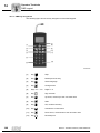
Operator Terminals ......................................................................................... 145
14.1 MFG11A keypad ..................................................................................... 145
14.2 DBG keypad............................................................................................ 147
15
MOVILINK® Unit Profile .................................................................................. 155
15.1 Coding of the process data ..................................................................... 155
15.2 Sample program for Simatic S7 and fieldbus.......................................... 159
16
Parameters....................................................................................................... 161
16.1 MQ.. parameter list ................................................................................. 161
17
Service ............................................................................................................. 163
17.1 Bus diagnostics with MOVITOOLS® ....................................................... 163
17.2 Extended storage.................................................................................... 170
17.3 Procedure when maintenance has been neglected ................................ 170
17.4 Disposal .................................................................................................. 170
18
Technical Data................................................................................................. 171
18.1 MFI21, MFI22, MFI32 INTERBUS interface (copper line) ...................... 171
18.2 MQI21, MQI22, MQI32 INTERBUS interface (copper line)..................... 172
18.3 MFI23, MFI33 INTERBUS interface (fibre optic cable) ........................... 173
18.4 Field distributors...................................................................................... 174
19
Address List .................................................................................................... 176
Index................................................................................................................. 185
Manual – InterBus Interfaces, Field Distributors
5
Valid Components
1
1
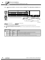
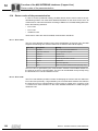
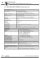
Valid Components
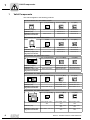
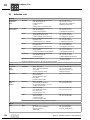
This manual applies to the following products:
Connection module ..Z.1. with fieldbus interface
INTERBUS (copper)
INTERBUS (FO)
INTERBUS (copper) with
integrated minicontroller
4 x I / 2 x O (terminals)
4 x I / 2 x O (M12)
6 x I (M12)
MFI21A/Z11A
MFI22A/Z11A
MFI32A/Z11A
-
MFI23F/Z11A
MFI33F/Z11A
MQI21A/Z11A
MQI22A/Z11A
MQI32A/Z11A
no I/O
4 x I / 2 x O (M12)
6 x I (M12)
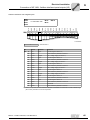
MFI21A/Z13A
MFI22A/Z13A
MFI32A/Z13A
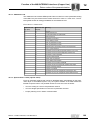
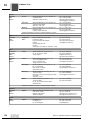
Field distributor ..Z.3. with fieldbus interface
INTERBUS (copper)
INTERBUS (FO)
INTERBUS (copper) with
integrated minicontroller
-
MFI23F/Z13A
MFI33F/Z13A
MQI21A/Z13A
MQI22A/Z13A
MQI32A/Z13A
4 x I / 2 x O (terminals)
4 x I / 2 x O (M12)
6 x I (M12)
MFI21A/Z16F/AF0
MFI22A/Z16F/AF0
MFI32A/Z16F/AF0
Field distributor ..Z.6. with fieldbus interface
INTERBUS (copper)
INTERBUS (FO)
INTERBUS (copper) with
integrated minicontroller
-
MFI23F/Z16F/AF0
MFI33F/Z16F/AF0
MQI21A/Z16F/AF0
MQI22A/Z16F/AF0
MQI32A/Z16F/AF0
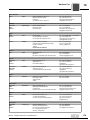
Field distributor ..Z.7. with fieldbus interface
INTERBUS (copper)
INTERBUS (FO)
INTERBUS (copper) with
integrated minicontroller
4 x I / 2 x O (terminals)
4 x I / 2 x O (M12)
6 x I (M12)
MFI21A/MM../Z17F.
MFI22A/MM../Z17F.
MFI32A/MM../Z17F.
-
MFI23F/MM../Z17F.
MFI33F/MM../Z17F.
MQI21A/MM../Z17F.
MQI22A/MM../Z17F.
MQI32A/MM../Z17F.
4 x I / 2 x O (terminals)
4 x I / 2 x O (M12)
6 x I (M12)
MFI21A/MM../Z18F./
AF0
MFI22A/MM../Z18F./
AF0
MFI32A/MM../Z18F./
AF0
-
MFI23F/MM../Z18F./
AF0
MFI33F/MM../Z18F./
AF0
MQI21A/MM../Z18F./AF0
MQI22A/MM../Z18F./
AF0
MQI32A/MM../Z18F./
AF0
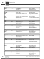
Field distributor ..Z.8. with fieldbus interface
INTERBUS (copper)
INTERBUS (FO)
INTERBUS (copper) with
integrated minicontroller
6
Manual – InterBus Interfaces, Field Distributors
General Information
How to use the operating instructions
2
General Information
2.1
How to use the operating instructions
2
The operating instructions are an integral part of the product and contain important information for operation and service. The operating instructions are written for all employees who assemble, install, startup, and service this product.
The operating instructions must be accessible and legible. Make sure that persons responsible for the system and its operation, as well as persons who work independently
on the unit, have read through the operating instructions carefully and understood them.
Consult SEW-EURODRIVE if you have any questions or if you require further information.
2.2
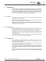
Structure of the safety notes
The safety notes in these operating instructions are structured as follows:
Symbol
SIGNAL WORD
Nature and source of hazard.
Possible consequence(s) if disregarded.
•
Symbol
Example:
Measure(s) to prevent the hazard.
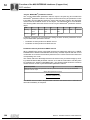
Signal word
Meaning
Consequences if disregarded
DANGER
Imminent danger
Severe or fatal injuries
WARNING
Possible hazardous situation
Severe or fatal injuries
CAUTION
Possible hazardous situation
Minor injuries
NOTICE
Potential damage to property.
Damage to the drive system or its environment
TIP
Useful information or tip.
Simplifies handling of the drive
system.
General danger
Specific danger,
e.g. electric shock
Manual – InterBus Interfaces, Field Distributors
7
General Information
Rights to claim under limited warranty
2
2.3
Rights to claim under limited warranty
A requirement of fault-free operation and fulfillment of any rights to claim under limited
warranty is that you adhere to the information in the operating instructions and this manual. Consequently, read the operating instructions and this manual before you start
working with the unit!
2.4
Exclusion of liability
It is essential that you observe the operating instructions to ensure safe operation and
to achieve the specified product characteristics and performance features of the fieldbus
interfaces, field distributors and MOVIMOT® MM..D inverters. SEW-EURODRIVE does
not assume liability for injury to persons or damage to equipment or property resulting
from non-observance of these operating instructions. In such cases, any liability for defects is excluded.
2.5
Copyright
© <2008> - SEW-EURODRIVE. All rights reserved.
Copyright law prohibits the unauthorized duplication, modification, distribution, and use
of this document, in whole or in part.
8
Manual – InterBus Interfaces, Field Distributors
Safety Notes
General
3
3
Safety Notes
The following basic safety notes must be read carefully to prevent injury to persons and
damage to property. The operator must ensure that the basic safety notes are read and
observed. Make sure that persons responsible for the plant and its operation, as well as
persons who work independently on the unit, have read through the operating instructions and manual carefully and understood them. If you are unclear about any of the information in this documentation, please contact SEW-EURODRIVE.
3.1
General
Never install or start up damaged products. Submit a complaint to the shipping company
immediately in the event of damage.
During operation, MOVIMOT® drives can have live, bare and movable or rotating parts
as well as hot surfaces, depending on their enclosure.
Removing covers without authorization, improper use as well as incorrect installation or
operation may result in severe injuries to persons or damage to property. Consult the
documentation for further information.
3.2
Target group
Only qualified personnel is authorized to install, startup or service the units or correct
unit faults (observing IEC 60364 and CENELEC HD 384 or DIN VDE 0100 and
IEC 60664 or DIN VDE 0110 as well as national accident prevention guidelines).
Qualified personnel in the context of these basic safety notes are: All persons familiar
with installation, assembly, startup and operation of the product who possess the necessary qualifications.
Any activities regarding transportation, storage, operation, and disposal must be carried
out by persons who have been instructed appropriately.
3.3
Designated use
The field distributors and fieldbus interfaces are intended for industrial systems. They
comply with the applicable standards and regulations and meet the requirements of the
Low Voltage Directive 73/23/EEC.
You must observe the technical data and information on the connection requirements
as provided on the nameplate and in the documentation.
Do not start up the unit (operate in the designated fashion) until you have established
that the machine complies with the EMC Directive 2004/108/EC and that the end product categorically conforms to Machinery Directive 98/37/EC (with reference to
EN 60204).
MOVIMOT® inverters comply with the regulations of the Low Voltage Directive 2006/95/
EC. The standards given in the declaration of conformity are used for the MOVIMOT®
inverter.
Manual – InterBus Interfaces, Field Distributors
9
Safety Notes
Other applicable documentation
3
3.3.1
Safety functions
The field distributors, fieldbus interfaces and MOVIMOT® inverters may not perform
safety functions unless these functions are described and expressly permitted.
If MOVIMOT® inverters are used in safe applications, you must observe the supplemental documentation "Safe Disconnection for MOVIMOT®". Use only those components in
safety applications that were explicitly designed and delivered for this purpose by
SEW-EURODRIVE.
3.3.2
Hoist applications
When using MOVIMOT® inverters in hoist applications, you must observe the special
configuration and settings for hoist applications specified in the operating instructions for
MOVIMOT®.
MOVIMOT® inverters are not designed for use as a safety device in hoist applications.
3.4
Other applicable documentation
Note also the following documentation:
3.5
•
"DR/DV/DT/DTE/DVE AC Motors, CT/CV Asynchronous Servomotors" operating
instructions
•
"AC Motors DRS/DRE/DRP" operating instructions
•
"MOVIMOT® MM..C" and "MOVIMOT® MM..D" operating instructions
•
"IPOSplus® Positioning and Sequence Control" manual
Transportation, storage
You must observe the notes on transportation, storage and proper handling. Comply
with the requirements for climatic conditions stated in section "Technical Data". Tighten
installed eyebolts securely. They are designed for the weight of the MOVIMOT® drive.
Do not attach any additional loads. Use suitable, sufficiently rated handling equipment
(e.g. rope guides) if required.
3.6
Installation
The units must be installed and cooled according to the regulations and specifications
in the corresponding documentation.
Protect the field distributors, fieldbus interfaces and MOVIMOT® inverters from improper
strain.
The following applications are prohibited unless the unit is explicitly designed for such
use:
10
•
Use in potentially explosive atmospheres.
•
Use in areas exposed to harmful oils, acids, gases, vapors, dust, radiation, etc.
•
Use in non-stationary applications with strong mechanical oscillation and impact
loads.
Manual – InterBus Interfaces, Field Distributors
Safety Notes
Electrical Connection
3.7
3
Electrical Connection
Observe the applicable national accident prevention guidelines when working on live
field distributors, fieldbus interfaces and MOVIMOT® inverters (e.g. BGV A3).
Electrical installation is to be carried out in compliance with pertinent regulations (e.g.
cable cross sections, fusing, protective conductor connection). For any additional information, refer to the applicable documentation.
You will find notes on EMC-compliant installation, such as shielding, grounding, arrangement of filters and routing of lines, in the documentation of the MOVIMOT® inverter. The manufacturer of the machine or system is responsible for maintaining the
limits established by the EMC legislation.
Protective measures and protection devices must comply with the regulations in force
(e.g. EN 60204 or EN 61800-5-1).
3.8
Safe disconnection
The field distributors and fieldbus interfaces meet all requirements for safe disconnection of power and electronics connections in accordance with EN 61800-5-1. All connected circuits must also satisfy the requirements for safe disconnection.
3.9
Operation
Systems with integrated field distributors, fieldbus interfaces and MOVIMOT® inverters
must be equipped with additional monitoring and protection devices according to the applicable safety guidelines, such as the law governing technical equipment, accident prevention regulations, etc. Additional protective measures may be necessary for applications with increased potential risk.
Do not touch live components or power connections immediately after disconnecting the
MOVIMOT® inverter, the field distributor (if installed) or the bus module (if installed) from
the supply voltage because there may still be some charged capacitors. Wait at least for
1 minute after having switched off the supply voltage.
As soon as supply voltage is present at the field distributor, the fieldbus interfaces and
the MOVIMOT® inverter, the housings must be closed, which means that:
•
The MOVIMOT® inverter must be screwed on.
•
The connection box cover of the field distributor (if installed) and the fieldbus
interface (if installed) must be screwed on.
•
The connector of the hybrid cable (if installed) must be connected and screwed on.
Important: The maintenance switch of the field distributor (if installed) only disconnects
the connected MOVIMOT® drive or motor from the power supply system. The terminals
of the field distributor remain connected to the supply voltage even after the maintenance switch is activated.
The fact that the status LED and other display elements are no longer illuminated does
not indicate that the unit has been disconnected from the power supply and no longer
carries any voltage.
Mechanical blocking or internal safety functions of the unit can cause a motor standstill.
Eliminating the cause of the problem or performing a reset may result in the drive restarting automatically. If, for safety reasons, this is not permitted for the driven machine,
disconnect the unit from the supply system before correcting the error.
Caution: Danger of burns: The surface temperature of the MOVIMOT® drive and of ex-
Manual – InterBus Interfaces, Field Distributors
11
3
Safety Notes
Operation
ternal options, e.g. the heat sink of the braking resistor, can exceed 60 °C during operation!
12
Manual – InterBus Interfaces, Field Distributors
Safety Notes
Supplementary safety notes for field distributors
3.10
3
Supplementary safety notes for field distributors
3.10.1 MFZ.3. field distributor
•
Disconnect the unit from the power supply system before removing the fieldbus
interface or the motor connector. Dangerous voltages may still be present for up to 1
minute after disconnection from the power supply.
•
The fieldbus interface and the connector of the hybrid cable must be connected to
the field distributor and fastened during operation.
3.10.2 MFZ.6. field distributor
•
Before removing the connection box cover for the power supply connection,
disconnect the unit from the power supply system. Dangerous voltages may still be
present for up to 1 minute after disconnection from the power supply.
•
Important: The switch only disconnects the MOVIMOT® inverter from the power
supply system. The terminals of the field distributor are still connected to the power
supply after activating the maintenance switch.
•
During operation, the connection box cover for the power supply connection and the
connector of the hybrid cable must be connected to the field distributor and fastened.
3.10.3 MFZ.7. field distributor
•
Before removing the MOVIMOT® inverter, disconnect the unit from the power supply
system. Dangerous voltages may still be present for up to 1 minute after
disconnection from the power supply.
•
The MOVIMOT® inverter and the connector of the hybrid cable must be connected
to the field distributor and fastened during operation.
3.10.4 MFZ.8. field distributor
•
Disconnect the unit from the power supply system before removing the connection
box cover for the power supply connection or the MOVIMOT® inverter. Dangerous
voltages may still be present for up to 1 minute after disconnection from the power
supply.
•
Important: The maintenance switch only disconnects the connected motor from the
power supply system. The terminals of the field distributor are still connected to the
power supply after activating the maintenance switch.
•
The connection box cover for the power supply connection, the MOVIMOT® inverter
and the connector of the hybrid cable must be connected to the field distributor and
fastened during operation.
Manual – InterBus Interfaces, Field Distributors
13
Unit Design
Fieldbus interfaces
4
4
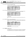
Unit Design
4.1
Fieldbus interfaces
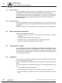
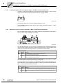
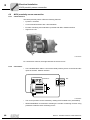
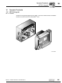
4.1.1
MF.21/MQ.21 fieldbus interface
[1]
[2]
1132777611
[1]
[2]
4.1.2
Diagnostic LEDs
Diagnostic interface (below screw fitting)
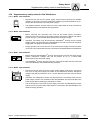
MF.22, MF.32, MQ.22, MQ.32 fieldbus interface
[4]
[3]
[1]
[2]
1132781835
[1]
[2]
[3]
[4]
14
Diagnostic LEDs
Diagnostic interface (below screw fitting)
M12 connection sockets
Status LED
Manual – InterBus Interfaces, Field Distributors
Unit Design
Fieldbus interfaces
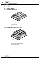
4.1.3
4
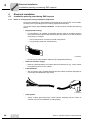
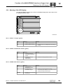
MFI23, MFI33 fieldbus interface with rugged line connector (INTERBUS only)
4
3
4
DI
5
DI
2
DI
3
DI
0
DI
1
DI
RC
1
US
TR
MF
I IN
TE
RB
US
IB
AG
DI
2
US
1
FO
2
FO
RD
-F
YS
S
RL
(X12)
1
6
2
(X11)
5
1397550603
[1]
[2]
[3]
[4]
[5]
[6]
4.1.4
Diagnostic LEDs
Diagnostic interface (below screw fitting)
M12 connection sockets
Status LED
Rugged line connection "Remote IN" (incoming remote bus and DC 24 V supply)
Rugged line connection "Remote OUT" (outgoing remote bus and DC 24 V supply)
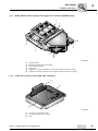
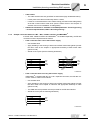
Underside of interface unit (all MF../MQ.. interfaces)
[1]
[2]
[3]
1132786955
[1]
[2]
[3]
Connection to connection module
DIP switches (dependent on variant)
Seal
Manual – InterBus Interfaces, Field Distributors
15
Unit Design
Fieldbus interfaces
4
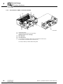
4.1.5
Unit structure of MFZ.. connection module
[2]
[1]
[3]
[5]
[4]
[3]
[3]
[6]
[4]
1136176011
[1]
[2]
[3]
[4]
[5]
[6]
Terminal strip (X20)
Isolated terminal block for 24 V through-wiring
(Caution: do not use for shielding.)
M20 cable gland
M12 cable gland
Grounding terminal
For DeviceNet and CANopen: Micro-style connector/M12 connector (X11)
For AS-Interface: AS-interface M12 connector (X11)
The scope of delivery includes 2 EMC cable glands.
16
Manual – InterBus Interfaces, Field Distributors
Unit Design
INTERBUS interfaces – unit designation
4.2
4
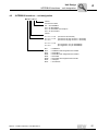
INTERBUS interfaces – unit designation
MFI 21 A / Z11 A
Variant
Connection module:
Z11 = for INTERBUS
Z21 = for PROFIBUS
Z31 = for DeviceNet and CANopen
Z61 = for AS-Interface
Variant
21 = 4 x I / 2 x O
22 = 4 x I / 2 x O
32 = 6 x I
(connection via terminals)
(connection via plug connector + terminals)
(connection via plug connector + terminals)
23 = 4 x I / 2 x O
33 = 6 x I
(FO rugged line, only for INTERBUS)
(FO rugged line, only for INTERBUS)
MFI..
MQI..
MFP..
MQP..
MFD..
MQD..
MFO..
MFK..
Manual – InterBus Interfaces, Field Distributors
= INTERBUS
= INTERBUS with integrated minicontroller
= PROFIBUS
= PROFIBUS with integrated minicontroller
= DeviceNet
= DeviceNet with integrated minicontroller
= CANopen
= AS-Interface
17
Unit Design
Field distributors
4
4.3
Field distributors
4.3.1
MF../Z.3., MQ../Z.3. field distributors
[6]
[7]
[5]
[4]
[3]
[8]
[9]
[5]
[4]
[10]
[3]
[9]
[2]
[1]
1136195979
[1]
[2]
[3]
[4]
[5]
[6]
[7]
[8]
[9]
[10]
18
For DeviceNet and CANopen: Micro-style connector/M12 connector (X11)
For AS-Interface: AS-interface M12 connector (X11)
2 x M20 x 1.5
2 x M25 x 1.5
2 x M16 x 1.5 (scope of delivery includes two EMC cable glands)
Terminals for fieldbus connection (X20)
Terminals for 24 V connection (X21)
Terminals for power supply and PE connection (X1)
Equipotential bonding connection
Hybrid cable connection; connection to MOVIMOT® (X9)
Manual – InterBus Interfaces, Field Distributors
Unit Design
Field distributors
4.3.2
4
MF../Z.6., MQ../Z.6. field distributors
[5]
[4]
[7]
[6]
[8] [3] [9]
3
X1
1
X1
X2
[3]
2
X1
X1
6
X1
5
X1
4
X3
[2]
[1]
1136203659
[1]
[2]
[3]
[4]
[5]
6 x M20 x 1.5 (scope of delivery includes two EMC cable glands)
For DeviceNet and CANopen: Micro-style connector/M12 connector (X11), see the following figure:
For AS-Interface: AS-Interface M12 connector (X11), see following figure:
1136438155
2 x M25 x 1.5
Equipotential bonding connection
Hybrid cable connection; connection to MOVIMOT® inverter (X9)
Maintenance switch with line protection (triple lock, color: black/red)
Only for MFZ26J: Optional integrated feedback for position of the maintenance switch.
The feedback is evaluated at digital input DI0 (section "Connection of MF../MQ.. fieldbus interface
inputs/outputs (I/O)" (see page 64).
Ø 5 – Ø 8 mm
I ON
0 OFF
0 OFF
I ON
1136352395
[6]
[7]
[8]
[9]
Terminals for power supply and PE connection (X1)
Terminals for bus, sensor, actuator, 24 V connection (X29)
Pluggable terminal "Safety Power" for 24 V MOVIMOT® supply (X40)
Terminal block for 24 V through-wiring (X29), internal connection to 24 V on X20
Manual – InterBus Interfaces, Field Distributors
19
Unit Design
Field distributors
4
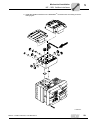
4.3.3
MF../MM../Z.7., MQ../MM../Z.7. field distributors
[8]
[3]
[4]
[6]
[5]
[7]
[9]
[10]
[11]
[12]
5
X1
[3]
[2]
[1]
1136447627
[1]
[2]
2 x M25 x 1.5 cable glands
5 x M20 x 1.5 cable gland (scope of delivery includes two EMC cable glands)
For DeviceNet and CANopen: Micro-style connector/M12 connector (X11), see the following figure:
For AS-Interface: AS-Interface M12 connector (X11), see following figure:
[3]
[4]
[5]
[6]
[7]
[8]
[9]
[10]
[11]
[12]
Equipotential bonding connection
Hybrid cable connection; connection to AC motor (X9)
Terminals for bus, sensor, actuator, 24 V connection (X29)
Pluggable terminal "Safety Power" for 24 V MOVIMOT® supply (X40)
Terminal block for 24 V through-wiring (X29), internal connection to 24 V on X20
MOVIMOT® inverter
Connection to the MOVIMOT® inverter
Terminals for enabling the direction of rotation
Terminals for power supply and PE connection (X1)
Terminal for integrated brake resistor
1136456331
20
Manual – InterBus Interfaces, Field Distributors
Unit Design
Field distributors
4.3.4
4
MF../MM../Z.8., MQ../MM../Z.8. field distributors
[5]
[6]
[7]
[8]
[9]
3
X1
12
X
1
X1
X2
[4]
[3]
6
X1
[10]
5
X1
4
X1
X3
[2]
[1]
1136479371
[1]
[2]
[3]
[4]
6 x M20 x 1.5 cable gland (scope of delivery includes two EMC cable glands)
For DeviceNet and CANopen: Micro-style connector/M12 connector (X11), see the following figure:
For AS-Interface: AS-Interface M12 connector (X11), see following figure:
1136438155
2 x M25 x 1.5 cable gland
Terminals for power supply and PE connection (X1)
Maintenance switch (triple lock, color: black/red)
Only for MFPZ28J: Optional integrated feedback for position of the maintenance switch. The feedback
is evaluated at digital input DI0 (section "Connection of MF../MQ.. fieldbus interface inputs/outputs (I/
O)" (see page 64).
Ø 5 – Ø 8 mm
I ON
0 OFF
0 OFF
I ON
1136352395
[5]
[6]
[7]
[8]
[9]
[10]
MOVIMOT® inverter
Terminals for bus, sensor, actuator, 24 V connection (X29)
Pluggable terminal "Safety Power" for 24 V MOVIMOT® supply (X40)
Terminal block for 24 V through-wiring (X29), internal connection to 24 V on X20
Hybrid cable connection; connection to AC motor (X9)
Equipotential bonding connection
Manual – InterBus Interfaces, Field Distributors
21
Unit Design
INTERBUS field distributors – unit designation
4
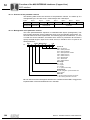
4.4
INTERBUS field distributors – unit designation
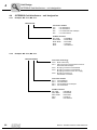
4.4.1
Example: MF../Z.3., MQ../Z.3.
MFI21A/Z13A
Connection module
Z13
= for INTERBUS
Z23
= for PROFIBUS
Z33
= For DeviceNet and CANopen
Z63
= For AS-Interface
Fieldbus interface
MFI../MQI..
= INTERBUS
MFP../MQP..
= PROFIBUS
MFD../MQD.. = DeviceNet
MFO..
= CANopen
MFK..
= AS-Interface
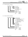
4.4.2
Example: MF../Z.6., MQ../Z.6.
MFI21A/Z16F/AF0
Connection technology
AF0 = Metric cable entry
AF1 = with micro-style connector/M12 connector
DeviceNet and CANopen
AF2 = M12 plug connector for PROFIBUS
AF3 = M12 plug connector for PROFIBUS +
M12 plug connector for DC 24 V supply
AF6 = M12 plug connector for
AS-Interface connection
Connection module
Z16 = For INTERBUS
Z26 = For PROFIBUS
Z36 = For DeviceNet and CANopen
Z66 = For AS-Interface
Fieldbus interface
= INTERBUS
MFI../MQI..
= PROFIBUS
MFP../MQP..
MFD../MQD.. = DeviceNet
= CANopen
MFO..
= AS-Interface
MFK..
22
Manual – InterBus Interfaces, Field Distributors
Unit Design
INTERBUS field distributors – unit designation
4.4.3
4
Example: MF../MM../Z.7., MQ../MM../Z.7.
MFI22A/MM15C-503-00/Z17F 0
Connection type
0= /1=
Connection module
Z17 = for INTERBUS
Z27 = for PROFIBUS
Z37 = for DeviceNet and CANopen
Z67 = for AS-Interface
MOVIMOT® inverter
Fieldbus interface
MFI../MQI..
= INTERBUS
MFP../MQP..
= PROFIBUS
MFD../MQD..
= DeviceNet
MFO..
= CANopen
MFK..
= AS-Interface
4.4.4
Example: MF../MM..Z.8., MQ../MM../Z.8.
MFI22A/MM22C-503-00/Z18F 0/AF0
Connection technology
AF0 = Metric cable entry
AF1 = with micro-style connector/M12 connector
DeviceNet and CANopen
AF2 = M12 plug connector for PROFIBUS
AF3 = M12 plug connector for PROFIBUS +
M12 plug connector for DC 24 V supply
AF6 = M12 plug connector for
AS-Interface connection
Connection type
0= /1=
Connection module
Z18 = for INTERBUS
Z28 = for PROFIBUS
Z38 = for DeviceNet and CANopen
Z68 = for AS-Interface
MOVIMOT® inverter
Fieldbus interface
MFI../MQI..
= INTERBUS
MFP../MQP..
= PROFIBUS
MFD../MQD..
= DeviceNet
MFO..
= CANopen
MFK..
= AS-Interface
Manual – InterBus Interfaces, Field Distributors
23
Mechanical Installation
Installation instructions
5
5
Mechanical Installation
5.1
Installation instructions
TIP
On delivery, field distributors are equipped with transportation protection covering the
plug connector of the outgoing motor circuit (hybrid cable).
This only guarantees enclosure IP40. To attain the specified enclosure rating, remove
the transport protection and plug on the appropriate mating connector. Screw them together.
5.1.1
5.1.2
24
Assembly
•
Mount field distributors on a level, vibration-proof and torsionally rigid support
structure only.
•
Use M5 screws with matching washers to connect the MFZ.3 field distributor. Tighten
the screws with a torque wrench (permitted tightening torque 2.8 – 3.1 Nm (25 – 27
lb.in)).
•
Use M6 screws and suitable washers for installing MFZ.6, MFZ.7 or MFZ.8 field
distributors. Tighten the screws with a torque wrench (permitted tightening torque 3.1
– 3.5 Nm (27 – 31lb.in)).
Installation in damp locations or in the open
•
Use suitable screw fittings for the cables (use reducing adapters if necessary).
•
Seal open cable entries and M12 connection sockets with screw plugs.
•
When the cable entry is on the side of the unit, route the cable using a drip loop.
•
Check and, if necessary, clean the sealing surfaces before re-mounting the fieldbus
interface/the connection box cover.
Manual – InterBus Interfaces, Field Distributors
Mechanical Installation
Tightening torques
5.2
Tightening torques
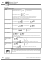
5.2.1
MOVIMOT® inverter
5
1138500619
®
Tighten the screws on the MOVIMOT inverter using 3.0 Nm (27 lb.in) working diagonally across.
5.2.2
Fieldbus interfaces/connection box cover
1138504331
Tighten the screws on the fieldbus interfaces or connection box cover using 2.5 Nm
(22 lb.in) working diagonally across.
Manual – InterBus Interfaces, Field Distributors
25
Mechanical Installation
Tightening torques
5
5.2.3
Screw plugs
1138509067
Tighten the blanking plugs and the screw plugs of potentiometer f1 and that of connection X50, if applicable, using 2.5 Nm (22 lb.in).
5.2.4
EMC cable glands
1138616971
Tighten EMC cable glands supplied by SEW-EURODRIVE using the following torque
ratings:
Screw fitting
Tightening torque
M12 x 1.5
2.5 Nm – 3.5 Nm (22 – 31 lb.in)
M16 x 1.5
3.0 Nm – 4.0 Nm (27 – 35 lb.in)
M20 x 1.5
3.5 Nm – 5.0 Nm (31 – 44 lb.in)
M25 x 1.5
4.0 Nm – 5.5 Nm (35 – 49 lb.in)
The cable retention in the cable gland must be able to withstand the following removal
force:
26
•
Cable with outer diameter > 10 mm: ≥ 160 N
•
Cable with outer diameter < 10 mm: = 100 N
Manual – InterBus Interfaces, Field Distributors
Mechanical Installation
Tightening torques
5.2.5
5
Motor cable
1138623499
Tighten screws for motor cables using 1.2 – 1.8 Nm (11 – 16 lb.in).
Manual – InterBus Interfaces, Field Distributors
27
Mechanical Installation
MF.. / MQ.. fieldbus interfaces
5
5.3
MF.. / MQ.. fieldbus interfaces
MF../MQ.. fieldbus interfaces can be installed as follows:
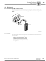
5.3.1
•
Installation on MOVIMOT® connection box
•
Installation in the field
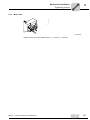
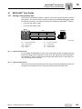
Installation on MOVIMOT® connection box
1. Remove knock outs on MFZ underside from the inside, as illustrated in the following
figure:
Z..
MF
[1]
1138656139
TIP
If necessary, debur any break lines that occur after the knock outs [1] have been removed.
28
Manual – InterBus Interfaces, Field Distributors
Mechanical Installation
MF.. / MQ.. fieldbus interfaces
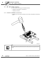
5
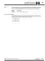
2. Install the fieldbus interface on the MOVIMOT® connection box according to the following figure:
.
Q.
/M
F..
M
1138663947
Manual – InterBus Interfaces, Field Distributors
29
Mechanical Installation
MF.. / MQ.. fieldbus interfaces
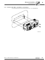
5
5.3.2
Installation in the field
The following figure shows the installation of an MF../MQ.. in the field: Fieldbus interface:
2
10
mm
82,5 mm
51
mm
M4
...
Z
MF
M4
[1]
.
Q.
/M
F..
M
.
Q.
/M
.
.
MF
1138749323
[1]
30
Length of screws min. 40 mm
Manual – InterBus Interfaces, Field Distributors
Mechanical Installation
Field distributors
5.4
Field distributors
5.4.1
Installation of MF../Z.3., MQ../Z.3. field distributors
5
The following figure shows the mounting dimensions for ..Z.3. field distributors:
175 mm
M5
50
mm
m
0m
10
M5
1138759307
Manual – InterBus Interfaces, Field Distributors
31
Mechanical Installation
Field distributors
5
5.4.2
Installation of MF../Z.6., MQ../Z.6. field distributors
The following figure shows the mounting dimensions for ..Z.6. field distributors:
m
5m
M6
180 mm
36
M6
1138795019
32
Manual – InterBus Interfaces, Field Distributors
Mechanical Installation
Field distributors
5.4.3
5
Installation of MF../MM../Z.7., MQ../MM../Z.7. field distributors
The following figure shows the mounting dimensions for ..Z.7. field distributors:
.7
mm
M6
59.5 mm
3
25
M6
1138831499
Manual – InterBus Interfaces, Field Distributors
33
Mechanical Installation
Field distributors
5
5.4.4
Installation of MF../MM../Z.8., MQ../MM../Z.8. field distributors (Size 1)
The following figure shows the mounting dimensions for ..Z.8. field distributors: (size 1):
m
0m
20
290 mm
M6
m
0m
27
M6
1138843147
34
Manual – InterBus Interfaces, Field Distributors
Mechanical Installation
Field distributors
5.4.5
5
Installation of MF../MM../Z.8., MQ../MM../Z.8. field distributors (Size 2)
The following figure shows the mounting dimensions for ..Z.8. field distributors: (size 2):
5
20
mm
350mm
M6
m
0m
29
M6
1138856203
Manual – InterBus Interfaces, Field Distributors
35
Electrical Installation
Installation planning considering EMC aspects
6
6
Electrical Installation
6.1
Installation planning considering EMC aspects
6.1.1
Notes on arranging and routing installation components
Successful installation of decentralized drives depends on selecting the correct cables,
providing correct grounding and a functioning equipotential bonding.
You should always apply relevant standards. You also need to consider the following
points:
•
Equipotential bonding
– Low-impedance, HF-capable equipotential bonding must be provided independent of the functional ground (PE terminal) (see also VDE 0113 or VDE 0100 part
540) using, for example
– Flat contact surface connection of metal components
– Flat grounding strips (HF stranded wire)
1138895627
– Do not use the cable shield of data lines for equipotential bonding.
•
Data lines and 24 V supply
– Must be routed separately from cables that emit interference (e.g. control cables
from solenoid valves, motor cables).
•
Field distributor
– We recommend using prefabricated SEW hybrid cables especially designed for
connecting field distributors and motors.
1138899339
•
Cable glands
– Select a cable gland with large contact surface shielding (see the notes on
selection and correct installation of cable glands).
36
Manual – InterBus Interfaces, Field Distributors
Electrical Installation
Installation planning considering EMC aspects
•
6
Cable shield
– The cable shield must have good EMC characteristics (high shield attenuation),
– It must protect the cable mechanically and as a shield,
– It must be connected with the unit's metal housing (via EMC metal cable glands)
at the flat contact surface cable ends (see the further notes in this chapter on
selection and correct installation of cable glands).
•
6.1.2
Additional information is available in the SEW publication "Drive Engineering
– Practical Implementation, EMC in Drive Engineering."
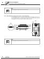
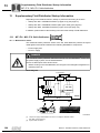
Sample connection between a MF.. / MQ.. fieldbus interface and MOVIMOT®
If the MF../MQ.. fieldbus interface and MOVIMOT® are installed separately, the RS-485
connection must be implemented as follows:
•
If the connection also carries the DC 24 V supply
– Use shielded lines
– Apply shielding to the housing of both units via EMC metal cable glands (consult
the other notes in this chapter on appropriate assembly of EMC metal cable
glands as well)
– Strand cores in pairs (see the following illustration)
RS+
RS-
RS+
GND
24V
GND
24V
RS-
1138904075
•
If the connection does not carry the DC 24 V supply
If MOVIMOT® is supplied with DC 24 V via a separate connection, the RS-485 connection must be carried out as follows:
– Use shielded lines
– Apply shielding to the housing of both units via EMC metal cable glands (consult
the other notes in this chapter on selection and appropriate assembly of cable
glands as well)
– The GND reference potential must be provided for the RS-485 interface
– Strand the cores (see the following illustration)
RS+
RSGND
1138973579
Manual – InterBus Interfaces, Field Distributors
37
Electrical Installation
Installation instructions for fieldbus interfaces/field distributors
6
38
6.2
Installation instructions for fieldbus interfaces/field distributors
6.2.1
Connecting supply system leads
•
The rated voltage and frequency of the MOVIMOT® inverter must correspond to the
data for the supply system.
•
Select the cable cross section according to the input current Iline for rated power (see
Technical Data).
•
Install line fuses at the beginning of the supply system line behind the supply bus
junction. Use D, DO, NH fuses or circuit breakers. Select the fuse size according to
the cable cross section.
•
Do not use a conventional earth leakage circuit-breaker as a protective device.
Universal current-sensitive earth-leakage circuit breakers ("type B") are permitted as
a protective device. During normal operation of MOVIMOT® drives, earth-leakage
currents > 3.5 mA can occur.
•
In accordance with EN 50178, a second PE connection (at least with the same crosssection as the supply system lead) is required parallel to the protective earth via
separate points of connection. Leakage currents > 3.5 mA may arise during
operation.
•
Use contactor switch contacts from utilization category AC-3 according to IEC 158 to
connect MOVIMOT® drives.
•
SEW-EURODRIVE recommends using earth-leakage monitors with pulse code
measuring in voltage supply systems with a non-grounded star point (IT systems).
Using such devices prevents the earth-leakage monitor mis-tripping due to the
ground capacitance of the inverter.
Manual – InterBus Interfaces, Field Distributors
Electrical Installation
Installation instructions for fieldbus interfaces/field distributors
6.2.2
6
Notes on PE connection and/or equipotential bonding
DANGER
Faulty PE connection.
Death, severe injuries or damage to property from electric shock.
•
•
The permitted tightening torque for the screw fitting is 2.0 - 2.4 Nm (18 - 21 lb.in).
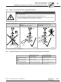
Observe the following notes regarding PE connection.
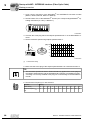
Prohibited assembly sequence
Recommendation: Assembly with forked
cable lug
Permitted for all cross sections
Assembly with thick solid wire
Permitted for cross sections up to
max. 2.5 mm2
M5
M5
2.5 mm²
[1]
323042443
323034251
323038347
[1] Forked cable lug suitable for M5 PE screws
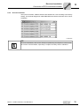
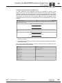
6.2.3
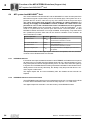
Permitted connection cross section and current carrying capacity of the terminals
Power terminals X1, X21
(screw terminals)
Control terminals X20
(cage clamp terminals)
Connection cross section
(mm2)
0.2 mm2 - 4 mm2
0.08 mm2 - 2.5 mm2
Connection cross section
(AWG)
AWG 24 – AWG 10
AWG 28 – AWG 12
Current carrying capacity
32 A max. continuous current
12 A max. continuous current
The permitted tightening torque of the power terminals is 0.6 Nm (5 Ib.in).
Manual – InterBus Interfaces, Field Distributors
39
Electrical Installation
Installation instructions for fieldbus interfaces/field distributors
6
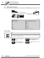
6.2.4
Looping through the DC 24 V supply voltage in the MFZ.1 module terminal box
•
Two M4 x 12 studs are located on the connection part of the DC 24 V supply. These
studs can be used for looping through the DC 24 V supply voltage.
1140831499
6.2.5
•
The terminal studs have a current carrying capacity of 16 A.
•
The permitted tightening torque for the hex nuts of the terminal studs is 1.2 Nm
(11 Ib.in) ± 20%.
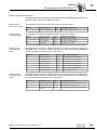
Additional connection options with MFZ.6, MFZ.7 and MFZ.8 field distributors
•
The connection part of the DC 24 V supply comprises a X29 terminal block with two
M4 x 12 studs and a pluggable X40 terminal.
1141387787
•
The X29 terminal block can be used as an alternative to the X20 terminal (section
"Unit Structure" (see page 14)) for looping through the DC 24 V supply voltage. Both
studs are connected internally to the 24 V connection at terminal X20.
Terminal assignment
No.
X29
•
Name
Function
1
24 V
24 V voltage supply for module electronics and sensors
(Studs, jumpered with terminal X20/11)
2
GND
0V24 reference potential for module electronics and sensors
(Studs, jumpered with terminal X20/13)
The plug-in terminal X40 ("Safety Power") is intended for the external DC 24 V supply
of the MOVIMOT® inverter via an emergency stop relay.
This setup allows for the operation of a MOVIMOT® drive in safety applications. For
more information, refer to the documentation on "Safe Disconnection for MOVIMOT®
MM.." of the respective MOVIMOT® drives.
Terminal assignment
No.
X40
40
Name
Function
1
24 V
24 V voltage supply for MOVIMOT® for disconnection with emergency stop relay
2
GND
0V24 reference potential for MOVIMOT® for disconnection with emergency stop
relay
Manual – InterBus Interfaces, Field Distributors
Electrical Installation
Installation instructions for fieldbus interfaces/field distributors
•
Terminal X29/1 is factory-jumpered with X40/1 and terminal X29/2 with X40/2, so that
the MOVIMOT® inverter is supplied by the same DC 24 V voltage as the fieldbus
interface.
•
The guide values for both studs are:
6
– Current carrying capacity: 16 A
– Permitted tightening torque for the hex nuts: 1.2 Nm (11 Ib.in) ± 20%.
•
The guide values for screw terminal X40 are:
– Current carrying capacity: 10 A
– Connection cross-section: 0.25 mm2 – 2.5 mm2 (AWG24 – AWG12)
– Permitted tightening torque: 0.6 Nm (5 Ib.in)
6.2.6
UL-compliant installation for field distributors
•
Use only copper cables in the temperature range 60/75 °C as the connection lead.
•
Use only tested units with a limited output voltage (V ≤ DC 30 V) and limited output
current (I ≤ 8 A) as an external DC 24 V voltage source.
•
The UL certification only applies to operation on voltage networks with voltages to
ground up to a maximum of 300 V.
Manual – InterBus Interfaces, Field Distributors
41
Electrical Installation
Installation instructions for fieldbus interfaces/field distributors
6
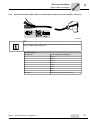
6.2.7
EMC metal cable glands
Install the EMC metal cable glands from SEW as follows:
[1]
1141408395
Important: Cut off insulation foil [1], do not fold it back.
42
Manual – InterBus Interfaces, Field Distributors
Electrical Installation
Installation instructions for fieldbus interfaces/field distributors
6.2.8
6
Wiring check
DANGER
It is necessary to check the wiring before energizing the system for the first time in order
to prevent injury to persons or damage to the system.
Severe or fatal injuries from electric shock.
•
•
•
•
•
•
•
•
•
•
Remove all fieldbus interfaces from the connection module
Disconnect all MOVIMOT® inverters from the connection module (only with MFZ.7,
MFZ.8)
Disconnect all plug connectors of the motor connection (hybrid cable) from the field
distributor
Check the insulation of the wiring in accordance with applicable national standards
Check the grounding.
Check insulation between the supply system cable and the DC 24 V cable
Check the insulation between mains cable and communication cable.
Check the polarity of the DC 24 V cable
Check the polarity of the communication line
Check the mains phase sequence
Ensure equipotential bonding between the fieldbus interfaces
•
Connect and fasten all motor connections (hybrid cable)
•
Connect and fasten all fieldbus interfaces
•
Install and fasten all MOVIMOT® inverters (for MFZ.7, MFZ.8 only)
•
Install all connection box covers
•
Cover any plug connections not in use
•
After the wiring
check
Manual – InterBus Interfaces, Field Distributors
43
Electrical Installation
Connection with INTERBUS (copper line)
6
6.3
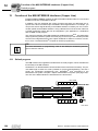
Connection with INTERBUS (copper line)
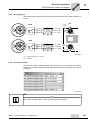
6.3.1
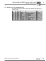
INTERBUS interfaces
The MFI../MQI.. fieldbus interfaces can be operated on both the remote bus and the installation remote bus. The principal distinguishing feature between these types of interfaces is the structure of the bus cable. Standard remote bus cables consist of 2-core cables twisted together in three pairs for data transmission. In addition to the data transmission wires, the installation remote bus may also carry the power supply for the MFI../
MQI.. and active sensors.
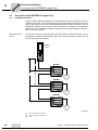
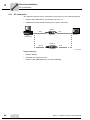
Remote bus connection
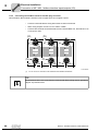
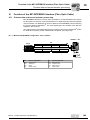
The typical remote bus connection for IP20 units involves a 9-pin D-sub plug. The following wiring examples show how MFI../MQI.. are connected to units on the input or output end using 9-pin D-sub plugs.
INTERBUS
Master
MFI/MQI
[1]
UL
MFI INTERBUS
RC
BA
TR
RD
SYS-F
[2]
[3]
[1]
MFI/MQI
UL
MFI INTERBUS
RC
BA
TR
RD
SYS-F
[3]
MFI/MQI
UL
MFI INTERBUS
RC
BA
TR
RD
SYS-F
[3]
1360658059
[1]
[2]
[3]
44
max. 400 m (max. 1,200 ft.)
max. 12.8 km (max. 8 miles)
Drive
Manual – InterBus Interfaces, Field Distributors
Electrical Installation
Connection with INTERBUS (copper line)
6
Line type
D9MFI (9-pin D-sub
to MFI)
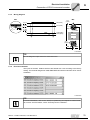
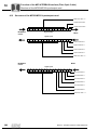
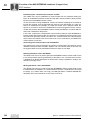
The incoming remote bus is picked off from the preceding INTERBUS module using a
9-pin D-sub plug.
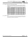
Line type MFI-D9
(MFI to 9-pin Dsub)
The subsequent INTERBUS module is connected using a 9-pin D-sub socket.
[4]
MFZ11 (InterBus)
X20
19 20 21 22 23 24 25 26 27 28 29 30 31 32 33 34 35 36
0
1
6 2
7 3
8 4
9 5
[5]
1
9
10 11 12 13 14 15 16 17 18
+ 24 VDC
BN
8
GY
7
YE
GN
6
PK
5
BN
4
GY
YE
3
[2]
[2]
[1]
DO
/DO
DI
/DI
COM
2
PK
GN
1
1
6
2
7
3
5
9
[3]
1 DO
6 /DO
2
DI
7
/DI
3 COM
1
6 2
7 3
8 4
9 5
[7]
[6]
[7]
1360755979
0
[1]
[2]
[3]
[4]
[5]
[6]
[7]
= Potential level 0
1
= Potential level 1
Incoming remote bus cable
Connect the shield of the incoming/outgoing remote bus cable to the MFZ.. housing
with an EMC metal cable gland
Outgoing remote bus cable
Assignment of terminals 19 - 36
chapter "Connection of MF../MQ.. fieldbus interface inputs/outputs (I/O)" (see page 64)
9-pin D-sub connector
9-pin D-sub socket
Strain relief
Manual – InterBus Interfaces, Field Distributors
45
Electrical Installation
Connection with INTERBUS (copper line)
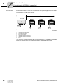
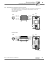
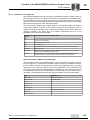
Installation remote
bus connection
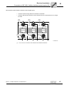
An 8-core cable is used for the installation remote bus. In addition to the strands for
transmission of data, the cable also carries the DC 24 V power supply for the MFI../MQI..
bus electronics and the active sensors.
[5]
[1]
IBS IP CBK
MFI/MQI
[4]
UL
RD
[6]
UL
RC
RC
MFIINTERBUS
MFI INTERBUS
TR
MFI/MQI
UL
RC
BA
SYS-F
[2]
MFI/MQI
BA
TR
RD
SYS-F
[6]
MFI INTERBUS
6
BA
TR
RD
SYS-F
[6]
[3]
1360870667
[1]
[2]
[3]
[4]
[5]
[6]
Incoming remote bus cable
Outgoing remote bus
24 V supply voltage
Installation remote bus terminal
Installation remote bus max. 50 m
Drive
The maximum number of modules that can be connected to an installation remote bus
terminal is determined by the current consumption of the individual modules.
46
Manual – InterBus Interfaces, Field Distributors
Electrical Installation
Connection with INTERBUS (copper line)
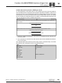
Line type CCO-I
→ MFI (IP65
round connector →
MFI terminals)
6
A special INTERBUS installation remote bus terminal is required to open an installation
remote bus segment. The installation remote bus can be connected to this bus terminal
(e.g. type IBS IP CBK 1/24F) using an IP65 round plug connector (type CCO-I).
[4]
MFZ11 (InterBus)
X20
19 20 21 22 23 24 25 26 27 28 29 30 31 32 33 34 35 36
0
[1]
[2]
1
2 9 87
3
6
4 5
DO
/DO
DI
/DI
4
5
6
7
8
1
9 10 11 12 13 14 15 16 17 18
BN
3
PK
GY
2
YE
GN
1
[3]
1
2
3
4
COM 5
RBST
PE
+24 V
0V
9
6
7
8
YE/GN
RD
BU
1360899723
[1]
[2]
[3]
[4]
0
= Potential level 0
1
= Potential level 1
IP65 round connector
Incoming installation remote bus cable
Connect shield of installation remote bus cable to the MFZ.. housing using an
EMC metal cable gland.
Assignment of terminals 19 - 36
chapter "Connection of MF../MQ.. fieldbus interface inputs/outputs (I/O)" (see page 64)
Manual – InterBus Interfaces, Field Distributors
47
Electrical Installation
Connection with INTERBUS (copper line)
6
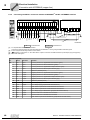
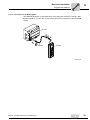
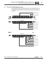
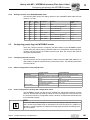
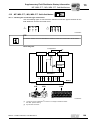
Connecting the MFZ11 connection module to MOVIMOT® via MFI.. INTERBUS interface
6.3.2
X20
MFZ11 (INTERBUS)
MOVIMOT®
[3]
19 20 21 22 23 24 25 26 27 28 29 30 31 32 33 34 35 36
MFZ11
9
10 11 12 13 14 15 16 17 18
R
L
f1/f2
K1a
K1b
RSRS+
8
GND
7
RS-
6
RS+
5
GND
4
24 V
GND
3
24 V
2
24V
1
0
1
24 V
+
[2]
COM
DI
/DI
DO
/DO
COM
DI
/DI
DO
[1]
[1]
[4]
[4]
/DO
MFI..
MQI..
+
24 VDC
1360905995
0
[1]
[2]
[3]
[4]
= Potential level 0
1
= Potential level 1
®
For separate MFZ11/MOVIMOT installation:
Connect the shield of the RS-485 cable with MFZ and the MOVIMOT® housing using the EMC metal cable gland
Ensure equipotential bonding between all bus stations
Assignment of terminals 19 - 36 as described in chapter "Connection of fieldbus interface inputs/outputs (I/O) (see page 64)".
EMC metal cable gland
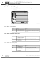
Terminal assignment
No.
X20
48
Name
Direction
Function
1
/DO
Input
Incoming remote bus, negated data send direction (green)
2
DO
Input
Incoming remote bus, data send direction (yellow)
3
/DI
Input
Incoming remote bus, negated data reception direction (pink)
4
DI
Input
Incoming remote bus, data reception direction (gray)
5
COM
-
Reference potential (brown)
6
/DO
Output
Outgoing remote bus, negated data send direction (green)
7
DO
Output
Outgoing remote bus, data send direction (yellow)
8
/DI
Output
Outgoing remote bus, negated data reception direction (pink)
9
DI
Output
Outgoing remote bus, data reception direction (gray)
10
COM
-
Reference potential (brown)
11
24 V
Input
24 V voltage supply for module electronics and sensors
12
24 V
Output
24 V voltage supply (jumpered with terminal X20/11)
13
GND
-
0V24 reference potential for module electronics and sensors
14
GND
-
0V24 reference potential for module electronics and sensors
15
24 V
Output
24 V voltage supply for MOVIMOT® (jumpered with terminal X20/11)
16
RS+
Output
Communication link to MOVIMOT® terminal RS+
17
RS-
Output
Communication link to MOVIMOT® terminal RS-
18
GND
-
0V24 reference potential for MOVIMOT® (jumpered with terminal X20/13)
Manual – InterBus Interfaces, Field Distributors
Electrical Installation
Connection with INTERBUS (copper line)
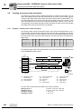
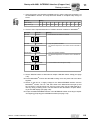
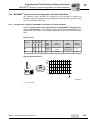
6.3.3
6
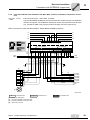
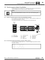
Connection MFZ13 field distributor with MFI../MQI.. interface (installation remote bus connection)
Line type
IP65 round connector → MFI../MQI.. terminals
CCO-I
→ MFI
A special INTERBUS installation remote bus terminal is required to open an installation
remote bus segment. The installation remote bus can be connected to this bus terminal
(e.g. type IBS IP CBK 1/24F) using an IP65 round plug connector (type CCO-I).
MFZ13 connection module with MFI21/MQI21, MFI22/MQI22 INTERBUS interface
5
4
3
2
L3
L3
4 mm 2 (AWG10)
X21
1
2
24V2
GND2
7
8
GND2
6
GND2
5
V2I24
4
V2I24
3
GND
24 V
2
GND
10 1
24 V
9
COM
/DI
DO
4 mm 2 (A WG10)
1
PE
6
/DO
COM
/DI
2
DO
1
/DO
YE/GN
MFZ13
7
2.5 mm 2 (AWG12)
X20
0
3 4 5 6 7 8
MFI21
MQI21
DI
+
8
DI
X1
MFI22
MQI22
L2
PE
L2
L1
PE
L1
L2
L1
L1
L3
L2
PE
L3
24V2
BU
RD
BN
GY
YE
PK
GN
GND2
[1]
[1]
[2]
DO
/DO
DI
/DI
1
2
3
4
BU
RD
YE
GN
GY
PK
BN
YE/GN
COM 5
RBST
PE
+24V
0V
[4]
9
6
7
8
[3]
Kl.3/X21
Kl.1/X21
Kl.2/X20
Kl.1/X 20
Kl.4 /X20
Kl.3 /X20
Kl.5 /X20
PE
1 8
2 9
7
3
6
4 5
1361313163
0
[1]
[2]
[3]
[4]
= Potential level 0
1
= Potential level 1
2
= Potential level 2
EMC metal cable gland
Incoming installation remote bus cable
Outgoing installation remote bus cable
IP65 round connector
Manual – InterBus Interfaces, Field Distributors
49
Electrical Installation
Connection with INTERBUS (copper line)
6
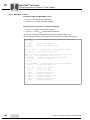
Terminal assignment
No.
X20
X21
50
Name
Direction
Function
1
/DO
Input
Incoming remote bus, negated data send direction (green)
2
DO
Input
Incoming remote bus, data send direction (yellow)
3
/DI
Input
Incoming remote bus, negated data reception direction (pink)
4
DI
Input
Incoming remote bus, data reception direction (gray)
5
COM
-
Reference potential (brown)
6
/DO
Output
Outgoing remote bus, negated data send direction (green)
7
DO
Output
Outgoing remote bus, data send direction (yellow)
8
/DI
Output
Outgoing remote bus, negated data reception direction (pink)
9
DI
Output
Outgoing remote bus, data reception direction (gray)
10
COM
-
Reference potential (brown)
1
24 V
Input
24 V voltage supply for module electronics, sensors and MOVIMOT®
2
24 V
Output
24 V voltage supply (jumpered with terminal X21/1)
3
GND
-
0V24 reference potential for module electronics, sensors and MOVIMOT®
4
GND
-
0V24 reference potential for module electronics, sensors and MOVIMOT®
5
V2I24
Input
24 V voltage supply for actuators (digital outputs)
6
V2I24
Output
24 V voltage supply for actuators (digital outputs) jumpered with terminal X21/5
7
GND2
-
0V24 reference potential for actuators
8
GND2
-
0V24 reference potential for actuators
Manual – InterBus Interfaces, Field Distributors
Electrical Installation
Connection with INTERBUS (copper line)
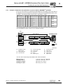
6
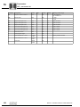
MFZ13 connection module with MFI32/MQI32 INTERBUS interface
4
3
2
1
L3
PE
RD
res.
res.
GND
4 mm 2 (AWG10)
X21
1
2 3 4
5 6
GND
24 V
10 1
COM
9
DI
COM
BN
8
/DI
DI
GY
7
DO
/DI
4
PK
3
DO
2
/DO
1
X20
0
5 6
YE
MFZ13
GN
YE/GN
2.5 mm 2 (AWG12)
4 mm 2(A WG10)
7
8
res.
5
res.
6
BU
MFI32
MQI32
7
/DO
+
8
24 V
X1
L3
PE
L2
PE
L2
L1
L1
L2
L1
L1
L3
L2
PE
L3
[1]
[1]
[2]
DO
/DO
DI
/DI
1
2
3
4
BU
RD
YE
GN
GY
PK
BN
YE/GN
COM 5
RBST
PE
+24V
0V
[4]
9
6
7
8
[3]
Kl.3/X21
Kl.1/X21
Kl.2/X20
Kl.1/X 20
Kl.4 /X20
Kl.3 /X20
Kl.5 /X20
PE
1 8
2 9
7
3
6
4 5
1361320971
0
[1]
[2]
[3]
[4]
= Potential level 0
1
= Potential level 1
EMC metal cable gland
Incoming installation remote bus cable
Outgoing installation remote bus cable
IP65 round connector
Manual – InterBus Interfaces, Field Distributors
51
Electrical Installation
Connection with INTERBUS (copper line)
6
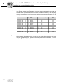
Terminal assignment
No.
X20
X21
52
Name
Direction
Function
1
/DO
Input
Incoming remote bus, negated data send direction (green)
2
DO
Input
Incoming remote bus, data send direction (yellow)
3
/DI
Input
Incoming remote bus, negated data reception direction (pink)
4
DI
Input
Incoming remote bus, data reception direction (gray)
5
COM
-
Reference potential (brown)
6
/DO
Output
Outgoing remote bus, negated data send direction (green)
7
DO
Output
Outgoing remote bus, data send direction (yellow)
8
/DI
Output
Outgoing remote bus, negated data reception direction (pink)
9
DI
Output
Outgoing remote bus, data reception direction (gray)
10
COM
-
Reference potential (brown)
1
24 V
Input
24 V voltage supply for module electronics, sensors and MOVIMOT®
2
24 V
Output
24 V voltage supply (jumpered with terminal X21/1)
3
GND
-
0V24 reference potential for module electronics, sensors and MOVIMOT®
4
GND
-
0V24 reference potential for module electronics, sensors and MOVIMOT®
5
-
-
Reserved
6
-
-
Reserved
7
-
-
Reserved
8
-
-
Reserved
Manual – InterBus Interfaces, Field Distributors
Electrical Installation
Connection with INTERBUS (copper line)
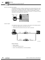
6.3.4
6
Connection MFZ16, MFZ17, MFZ18 field distributors with MFI../MQI.. INTERBUS interfaces (installation remote bus connection)
Line type
→ MFI
IP65 round connector → MFI../MQI.. terminals
CCO-I
A special INTERBUS installation remote bus terminal is required to open an installation
remote bus segment. The installation remote bus can be connected to this bus terminal
(e.g. type IBS IP CBK 1/24F) using an IP65 round plug connector (type CCO-I).
MFZ16, MFZ17, MFZ18 connection module with MFI21/MQI21, MFI22/MQI22 INTERBUS interface
4
5
6
7
8
GND2
GND2
V2I24
GND
V2I24
24V2
L3
PE
GND2
BU
RD
BN
GY
2
10 11 12 13 14 15 16 17 18
GND
9
24 V
8
24 V
7
DI
5
COM
4
/DI
3
PK
YE
GN
MFI22
MFI22
[5]
X20
24V2
GND2
MFI21
MQI21
4 mm 2 (A WG10)
1
0
6
DO
DO
/DO
2
COM
1
+
3
2.5 mm 2 (AWG12)
DI
MFZ18
2
19 20 21 22 23 24 25 26 27 28 29 30 31 32 33 34 35 36
1
2
/DI
YE/GN
MFZ17
1
L3
X1
L2
PE
L2
L1
PE
L1
L2
L1
L1
L2
PE
L3
/DO
MFZ16
L3
[1]
[1]
[2]
DO
/DO
DI
/DI
1
2
3
4
BU
RD
YE
GN
GY
PK
BN
YE/GN
COM 5
RBST 9
PE 6
+24V 7
0V 8
[4]
[3]
Kl.13
Kl.11
Kl.2
Kl.1
Kl.4
Kl.3
Kl.5
PE
1
2 98
7
3
6
4 5
1361521547
0
[1]
[2]
[3]
[4]
[5]
= Potential level 0
1
= Potential level 1
2
= Potential level 2
EMC metal cable gland
Incoming installation remote bus cable
Outgoing installation remote bus cable
IP65 round connector
Assignment of terminals 19 - 36 as described in chapter "Connection of fieldbus interface inputs/outputs (I/O) (see page 64)".
Manual – InterBus Interfaces, Field Distributors
53
Electrical Installation
Connection with INTERBUS (copper line)
6
Terminal assignment
No.
X20
54
Name
Direction
Function
1
/DO
Input
Incoming remote bus, negated data send direction (green)
2
DO
Input
Incoming remote bus, data send direction (yellow)
3
/DI
Input
Incoming remote bus, negated data reception direction (pink)
4
DI
Input
Incoming remote bus, data reception direction (gray)
5
COM
-
Reference potential (brown)
6
/DO
Output
Outgoing remote bus, negated data send direction (green)
7
DO
Output
Outgoing remote bus, data send direction (yellow)
8
/DI
Output
Outgoing remote bus, negated data reception direction (pink)
9
DI
Output
Outgoing remote bus, data reception direction (gray)
10
COM
-
Reference potential (brown)
11
24 V
Input
24 V voltage supply for module electronics and sensors
12
24 V
Output
24 V voltage supply (jumpered with terminal X20/11)
13
GND
-
0V24 reference potential for module electronics and sensors
14
GND
-
0V24 reference potential for module electronics and sensors
15
V2I24
Input
24 V voltage supply for actuators (digital outputs)
16
V2I24
Output
24 V voltage supply for actuators (digital outputs) jumpered with terminal X20/15
17
GND2
-
0V24 reference potential for actuators
18
GND2
-
0V24 reference potential for actuators
Manual – InterBus Interfaces, Field Distributors
Electrical Installation
Connection with INTERBUS (copper line)
6
MFZ16, MFZ17, MFZ18 connection module with MFI32/MQI32 INTERBUS interface
2
3
4
5
6
7
8
PE
MFZ17
1
L3
X1
L3
PE
L2
L1
L2
L1
PE
L1
L2
L1
L3
L2
PE
MFZ16
L3
4 mm 2 (A WG10)
19 20 21 22 23 24 25 26 27 28 29 30 31 32 33 34 35 36
1
2.5 mm2 (AWG12)
res.
res.
res.
res.
GND
X20
1
14 15 16 17 18
BU
GND
10 11 12 13
24 V
9
RD
COM
BN
8
24 V
DI
GY
7
COM
/DI
PK
0
6
DI
DO
5
YE
4
/DO
3
GN
MFI32
MQI32
2
/DI
+
1
DO
MFZ18
/DO
YE/GN
[5]
[1]
[1]
[2]
1
DO
/DO
DI
/DI
2
3
BU
RD
YE
GN
GY
PK
4
COM 5
RBST 9
PE 6
+24V 7
0V 8
2
[4]
1
9
BN
YE/GN
[3]
Kl.13
Kl.11
Kl.2
Kl.1
Kl.4
Kl.3
Kl.5
PE
8
3
4 5
7
6
1361594891
0
[1]
[2]
[3]
[4]
[5]
= Potential level 0
1
= Potential level 1
EMC metal cable gland
Incoming installation remote bus cable
Outgoing installation remote bus cable
IP65 round connector
Assignment of terminals 19 - 36 as described in chapter "Connection of fieldbus interface inputs/outputs (I/O) (see page 64)".
Manual – InterBus Interfaces, Field Distributors
55
Electrical Installation
Connection with INTERBUS (copper line)
6
Terminal assignment
No.
X20
56
Name
Direction
Function
1
/DO
Input
Incoming remote bus, negated data send direction (green)
2
DO
Input
Incoming remote bus, data send direction (yellow)
3
/DI
Input
Incoming remote bus, negated data reception direction (pink)
4
DI
Input
Incoming remote bus, data reception direction (gray)
5
COM
-
Reference potential (brown)
6
/DO
Output
Outgoing remote bus, negated data send direction (green)
7
DO
Output
Outgoing remote bus, data send direction (yellow)
8
/DI
Output
Outgoing remote bus, negated data reception direction (pink)
9
DI
Output
Outgoing remote bus, data reception direction (gray)
10
COM
-
Reference potential (brown)
11
24 V
Input
24 V voltage supply for module electronics and sensors
12
24 V
Output
24 V voltage supply (jumpered with terminal X20/11)
13
GND
-
0V24 reference potential for module electronics and sensors
14
GND
-
0V24 reference potential for module electronics and sensors
15
-
-
Reserved
16
-
-
Reserved
17
-
-
Reserved
18
-
-
Reserved
Manual – InterBus Interfaces, Field Distributors
Electrical Installation
Connecting INTERBUS with fiber-optic cable
6.4
Connecting INTERBUS with fiber-optic cable
6.4.1
Connecting the communication and the DC 24 V voltage supply
6
INTERBUS and the DC 24 V supply are installed using rugged line connectors.
[1]
[2]
1361730571
[1] Fiber optic cable (INTERBUS remote bus)
[2] VS1/VS2 voltage supply
TIPS
•
•
6.4.2
The connectors are not included in the SEW delivery. hey are available from
Phoenix Contact.
It is essential to observe the project planning and installation guidelines for the
rugged-line connection technology by Phoenix-Contact.
Assembling the bus connector
The connector plugs can be connected to the bus module in 4 different ways (see the
following figure).
DI4
DI4
DI5
DI2
G
DI0
RL
DI1
G
DIA
US1
RC
TR
MFI
IN
TE
RBU
S
IB
US2
FO
RD
2.
DIA
US1
US2
RC
FO
TR
IN
TE
RBU
S
IB
DI3
Remote OUT
(X12)
DI3
DI0
DI1
1
FO
RD
MFI
1.
DI5
DI2
SY
2
S-
F
1
FO
SY
2
F
S-
RL
Remote OUT
(X12)
Remote IN
(X11)
Remote IN
(X11)
4.
DI4
3.
DI5
DI2
DI3
DI0
FO
RD
DI3
DI0
DI1
1
FO
SY
2
S-
IB
G
DUIAS1
F
MFI
IN
TE
RBU
S
RL
Remote IN
(X11)
RL
TR
US2
IN
TE
RBU
S
US1
RC
RC
US2
RD
MFI
G
DIA
DI5
DI2
DI1
IB
Remote OUT
(X12)
DI4
TR
FO
1
FO
SY
2
S-
F
Remote OUT
(X12)
Remote IN
(X11)
1362417035
Manual – InterBus Interfaces, Field Distributors
57
Electrical Installation
Connecting INTERBUS with fiber-optic cable
6
WARNING
Assembling the connectors when energized.
Damage due to overvoltage or short circuit.
Only install the connector plugs when they are de-energized. Prior to assembling the
connectors disconnect the voltage supply.
WARNING
Improper handling of the connector clips.
Damage to the clip.
Do not use the clips to position the connectors on the bus module. Hold the connectors
by the housing to plug them in.
TIP
Connector plugs that are not in use must be equipped with a dummy plug to ensure the
enclosure.
Assembly
•
Disconnect the voltage supply.
•
Open the clip (1.) and push the plug all the way into the corresponding socket on the
bus module (2.)
•
Close the clip (3.)
DI4
DI5
DI2
DI4
DI3
DI0
DI1
1
US
TR
2
US
RD
1
FO
DI1
2
FO
IB
S-F
SY
G
DIA
US
RC
1
TR
MF
RC
RL
G
DIA
DI3
DI0
BU
S
MF
I IN
TE
RB
US
IB
DI5
DI2
US
RD
2
1
FO
FO
SY
2
S-F
RL
TE
R
I IN
2.
3.
1.
1362525835
58
Manual – InterBus Interfaces, Field Distributors
Electrical Installation
Connecting INTERBUS with fiber-optic cable
Disassembly
6.4.3
•
Disconnect the voltage supply.
•
Open the clip and pull the plug from the module.
6
Supply voltage
•
The two available supply voltages are used as follows:
– VS1: DC 24 V power supply for bus logic, sensors and MOVIMOT®
– VS2: Power supply for the actuators (for current consumption, see Technical
Data)
Pin assignment
DI4
DI5
DI2
DI3
DI0
DI1
DIA
G
RC
US
TR
1
MF
I IN
TE
RB
US
IB
2
US
RD
1
FO
2
FO
F
SSY
RL
+US1
US1
+US2
US2
+US1
US1
+US2
US2
+US1
US1
+US2
US2
+US1
US1
+US2
US2
1362657291
Manual – InterBus Interfaces, Field Distributors
59
Electrical Installation
Connecting INTERBUS with fiber-optic cable
6
6.4.4
Cable installation
Cabling for the plug connectors requires maintaining a distance that is dependent on the
bending radius of the cable type being used (observe the project planning and installation guidelines concerning rugged line connection technology from Phoenix-Contact).
Rmin
Rmin
1362939531
Cable lengths < 1 m
TIP
Cable lengths < 1 m are only permitted with the pre-fabricated IBS RL CONNECTIONLK special cable bridge from Phoenix Contact.
Observe the project planning and installation guidelines for the rugged-line connection
technology by Phoenix-Contact.
60
Manual – InterBus Interfaces, Field Distributors
Electrical Installation
Connecting INTERBUS with fiber-optic cable
6.4.5
6
Sample topology of an INTERBUS design with rugged line connection
INTERBUS
interface component
MFI. 3
MFI. 3
Remote bus
Rugged line bus terminal
Blind
connector
Remote bus
Remote bus
MFI. 3
Remote bus
Bus segment (max 400 m in copper
max. 35m/50m in polymere fibre
Remote bus max 12.8 km in copper and polymerer fibre
Remote bus line
MFI. 3
MFI. 3
Blind
connector
1362981259
TIP
The maximum distance between two remote bus nodes connected via fibre optic cables with fixed polymer fibers is 50 m. With flexible polymer fibers, the maximum distance is 35 m.
Manual – InterBus Interfaces, Field Distributors
61
Electrical Installation
Connecting INTERBUS with fiber-optic cable
6
Connecting the MFZ11 connection module to MOVIMOT® with MFI23/MFI33 INTERBUS interface
6.4.6
X20
MFZ11 (INTERBUS)
MOVIMOT®
[3]
19 20 21 22 23 24 25 26 27 28 29 30 31 32 33 34 35 36
res.
res.
res.
res.
res.
res.
res.
R
L
f1/f2
K1a
K1b
RSRS+
res.
1
10 11 12 13 14 15 16 17 18
GND
9
RS-
8
RS+
7
res.
6
24 V
5
res.
4
res.
3
res.
2
res.
0
1
res.
+
24V
MFZ11
[2]
MFI23
MFI33
[1]
[1]
1363048203
0
[1]
[2]
[3]
= Potential level 0
1
= Potential level 1
For separate MFZ11/MOVIMOT® installation:
Connect the shield of the RS-485 cable with MFZ and the MOVIMOT® housing using the EMC metal cable gland
Ensure equipotential bonding between all bus stations
Assignment of terminals 19 - 36 as described in chapter "Connection of fieldbus interface inputs/outputs (I/O) (see page 64)".
Terminal assignment
No.
X20
62
Name
Direction
Function
1 - 14
–
–
Reserved
15
24 V
Output
24 V voltage supply for MOVIMOT® (jumpered with terminal X20/11)
16
RS+
Output
Communication link to MOVIMOT® terminal RS+
17
RS-
Output
Communication link to MOVIMOT® terminal RS-
18
GND
–
0V24 reference potential for MOVIMOT® (jumpered with terminal X20/13)
Manual – InterBus Interfaces, Field Distributors
Electrical Installation
Connecting INTERBUS with fiber-optic cable
Connecting the MFZ13 field distributor with MFI23/MFI33
7
6
5
4
3
2
1
2
2
3
3
4
5
res.
res.
res.
6
7
res.
1
res.
res.
10
res.
res.
9
res.
res.
8
res.
res.
2
7
res.
4
X21
1
res.
3
4 mm (AWG10)
res.
2
MFI23
MFI33
res.
1
X20
0
5
6
res.
2.5 mm2 (AWG12)
MFZ13
4 mm 2 (AWG10)
res.
+
8
PE
X1
L3
PE
L3
L1
L2
L1
PE
L2
L2
L1
L3
L2
L1
L3
PE
6.4.7
6
1363115531
1
= Potential level 1
2
= Potential level 2
Connecting the MFZ16, MFZ17, MFZ18 field distributor with MFI23/MFI33
PE
X1
MFZ17
1
2
3
4
26
27
5
6
7
8
PE
L1
L3
L1
PE
L3
L2
L2
L2
L2
L3
L1
MFZ16
L3
L1
6.4.8
= Potential level 0
PE
0
29
30
31
[1]
4 mm 2 (AWG10)
21
22
23
24
25
1
33
34
35
36
17
18
2.5 mm2 (AWG12)
1
3
4
5
6
7
8
9
10
11
12
13
14
15
16
res.
res.
res.
res.
res.
res.
res.
res.
res.
res.
res.
res.
res.
res.
2
2
res.
0
1
res.
MFI23
MFI33
32
2
MFZ18
+
28
res.
20
res.
X20
19
1363185035
0
[1]
= Potential level 0
1
= Potential level 1
2
= Potential level 2
Assignment of terminals 19 - 36 as described in chapter "Connection of fieldbus interface inputs/outputs (I/O) (see page 64)".
Manual – InterBus Interfaces, Field Distributors
63
Electrical Installation
Connection of MF../MQ.. fieldbus interface inputs/outputs (I/O)
6
6.5
Connection of MF../MQ.. fieldbus interface inputs/outputs (I/O)
The power supply to the fieldbus interfaces is connected via terminals or M12 plug connectors.
6.5.1
Connecting the fieldbus interfaces via terminals
Fieldbus interfaces with 4 digital inputs and 2 digital outputs:
27
28
29
30
31
32
33
GND2
26
V2I24 [1]
DO1
25
1
GND2
GND2
24
DO 0
VO24
23
VO24
GND
22
GND
DI 1
21
DI 3
VO24
20
VO24
GND
19
MQ.21
MQ.22
GND
DI 0
X20
MF.21
MF.22
MF.23
in combination with
DI 2
MFZ.1
MFZ.6
MFZ.7
MFZ.8
34
35
36
2
1141534475
[1]
Only MFI23: reserved, all other MF.. modules: V2I24
No.
X20
1
= Potential level 1
2
= Potential level 2
Name
Direction
Function
19
DI0
Input
Control signal of sensor 11)
20
GND
-
0V24 reference potential for sensor 1
21
V024
Output
24 V voltage supply for sensor 11)
22
DI1
Input
Control signal of sensor 2
23
GND
-
0V24 reference potential for sensor 2
24
V024
Output
24 V voltage supply for sensor 2
25
DI2
Input
Control signal of sensor 3
26
GND
-
0V24 reference potential for sensor 3
27
V024
Output
24 V voltage supply for sensor 3
28
DI3
Input
Control signal of sensor 4
29
GND
-
0V24 reference potential for sensor 4
30
V024
Output
24 V voltage supply for sensor 4
31
DO0
Output
Control signal of actuator 1
32
GND2
-
0V24 reference potential for actuator 1
33
DO1
Output
Control signal of actuator 2
34
GND2
-
0V24 reference potential for actuator 2
24 V voltage supply for actuators
Only for MFI23: Reserved
Only for MFZ.6, MFZ.7 and MFZ.8: Jumpered with terminal 15 or 16
35
V2I24
Input
36
GND2
-
0V24 reference potential for actuators
Only for MFZ.6, MFZ.7 and MFZ.8: Jumpered with terminal 17 or 18
1) Used in conjunction with field distributors MFZ26J and MFZ28J for maintenance switch feedback signal (NO
contact). Evaluation via control is possible.
64
Manual – InterBus Interfaces, Field Distributors
Electrical Installation
Connection of MF../MQ.. fieldbus interface inputs/outputs (I/O)
6
Fieldbus interfaces with 6 digital inputs:
26
27
GND
25
res.
VO24
24
GND
GND
23
DI 5
DI 2
22
GND
VO24
21
DI 4
GND
20
VO24
DI 1
19
GND
VO24
MQ.32
GND
MF.32
MF.33
DI 0
X20
in combination with
DI 3
MFZ.1
MFZ.6
MFZ.7
MFZ.8
28
1
29
30
31
32
33
34
35
36
1141764875
1
No.
X20
= Potential level 1
Name
Direction
Function
19
DI0
Input
Control signal of sensor 11)
20
GND
-
0V24 reference potential for sensor 1
21
V024
Output
24 V voltage supply for sensor 11)
22
DI1
Input
Control signal of sensor 2
23
GND
-
0V24 reference potential for sensor 2
24
V024
Output
24 V voltage supply for sensor 2
25
DI2
Input
Control signal of sensor 3
26
GND
-
0V24 reference potential for sensor 3
27
V024
Output
24 V voltage supply for sensor 3
28
DI3
Input
Control signal of sensor 4
29
GND
-
0V24 reference potential for sensor 4
30
V024
Output
24 V voltage supply for sensor 4
31
DI4
Input
Control signal of sensor 5
32
GND
-
0V24 reference potential for sensor 5
33
DI5
Input
Control signal of sensor 6
34
GND
-
0V24 reference potential for sensor 6
35
res.
-
Reserved
36
GND
-
0V24 reference potential for sensors
1) Used in conjunction with field distributors MFZ26J and MFZ28J for maintenance switch feedback signal
(NO contact). Evaluation via control is possible.
Manual – InterBus Interfaces, Field Distributors
65
Electrical Installation
Connection of MF../MQ.. fieldbus interface inputs/outputs (I/O)
6
6.5.2
Connecting the fieldbus interfaces via M12 plug connector
MF.22, MQ.22, MF.23 fieldbus interfaces with 4 digital inputs and 2 digital outputs:
•
Connect sensors/actuators using either M12 sockets or terminals
•
When using outputs: Connect 24 V to V2I24 / GND2
•
Connect dual-channel sensors/actuators to DI0, DI2 and DO0. DI1, DI3 and DO1 can
no longer be used.
24 V
(V024)
24 V
(V024)
DI1
1
1
5
DI0
[1]
4
DI3
2
4
1
4
4
3
GND
GND2
DIO
DI2
DO0
DI1
DI3
DO1
24 V
(V024)
2
5
1
4
3
DI1
DO1
2
5
DO0
3
GND
24 V
(V024)
1
5
DI2
3
2
2
1
5
4
3
GND
DI3
GND
DO1
2
5
3
GND2
1141778443
[1]
Do not use DI0 in combination with field distributors MFZ26J and MFZ28J.
TIP
Connections that are not in use must be covered with M12 closing caps to guarantee
degree of protection IP65.
66
Manual – InterBus Interfaces, Field Distributors
Electrical Installation
Connection of MF../MQ.. fieldbus interface inputs/outputs (I/O)
6
MF.32, MQ.32, MF.33 fieldbus interfaces with 6 digital inputs:
•
Connect sensors using either M12 sockets or terminals.
•
Connect dual-channel sensors to DI0, DI2 and DI4. DI1, DI3 and DI5 can no longer
be used.
24 V
(V024)
24 V
(V024)
24 V
(V024)
DI1
1
1
5
DI0
[1]
4
2
4
1
4
4
3
GND
GND
DIO
DI2
DI4
DI1
DI3
DI5
24 V
(V024)
2
5
1
4
3
DI1
2
5
DI4
3
GND
24 V
(V024)
1
5
DI2
3
DI5
DI3
2
24 V
(V024)
2
5
4
3
GND
DI3
1
2
5
3
GND
DI5
GND
1141961739
[1]
Do not use DI0 in combination with field distributors MFZ26J and MFZ28J.
Manual – InterBus Interfaces, Field Distributors
67
Electrical Installation
NV26 proximity sensor connection
6
6.6
NV26 proximity sensor connection
6.6.1
Characteristics
The NV26 proximity sensor offers the following features:
•
6 pulses / revolution
•
24 increments/revolution with 4-fold evaluation
•
Encoder monitoring and evaluation is possible with MQ.. fieldbus interface
•
Signal level: HTL
1146134539
For constructive reasons, the angle between the sensors is 45°.
6.6.2
Connection
•
Use a shielded M12 cable to connect the NV26 proximity sensor to the DI0 and DI1
inputs of the MQ.. fieldbus interface.
MOVIMOT®
MQ..
NV26
1146334603
68
•
The current position can be checked by reading IPOS variable H511 (ActPosMot).
•
SEW-EURODRIVE recommends activating the encoder monitoring function using
parameter "P504 Encoder monitoring motor".
Manual – InterBus Interfaces, Field Distributors
Electrical Installation
NV26 proximity sensor connection
6.6.3
6
Wiring diagram
The following figure shows the pin assignment of NV25 sensors to the MQ.. fieldbus interface:
MQ..
NV26
24 V
(V024)
1
(UB )
PIN1
2
4
3
PNP
24 V (PIN1)
1
(GND)
PIN3
GND (PIN3)
(A / B) [1]
PIN4
쵰
[2]
DI0 (PIN4)
DI0
4
DIO
DI1
1
PIN1
PIN3
4
3
PNP
3
GND
쵰
NV26
2
2
5
(UB )
24 V (PIN1)
(GND)
GND (PIN3)
(A / B) [1]
PIN4
쵰
[2]
DI1 (PIN4)
24 V
(V024)
1
4
2
5
3
DI1
GND
쵰
1221377803
[1]
[2]
6.6.4
Encoder input track A or track B
Shielding
Encoder evaluation
The inputs of the MQ.. fieldbus interface are filtered with 4 ms according to the factory
setting. The terminal assignment "MQX ENCODER IN" switches this filter off for sensor
evaluation.
1146357259
TIP
For more information, refer to the "IPOSplus® positioning and sequence control" manual, section "IPOS for MQX", under "Proximity sensor evaluation".
Manual – InterBus Interfaces, Field Distributors
69
Electrical Installation
Connection of ES16 incremental encoder
6
6.7
Connection of ES16 incremental encoder
6.7.1
Characteristics
The ES16 incremental encoder offers the following features:
•
6 pulses / revolution
•
24 increments/revolution with 4-fold evaluation
•
Encoder monitoring and evaluation is possible with MQ.. fieldbus interface
•
Signal level: HTL
1146498187
6.7.2
Installation in combination with MQ.. fieldbus interface
•
Connect the ES16 incremental encoder to the inputs of the MQ.. fieldbus interface
using a shielded M12 cable, section "Wiring diagram" (see page 71).
MQ..
ES16
MOVIMOT®
1146714123
70
•
The current position can be checked by reading IPOS variable H511 (ActPosMot).
•
SEW-EURODRIVE recommends activating the encoder monitoring function using
parameter "P504 Encoder monitoring motor".
Manual – InterBus Interfaces, Field Distributors
Electrical Installation
Connection of ES16 incremental encoder
6.7.3
Wiring diagram
ES16
UB
UB
6
K1 K2 K0 K1 K2 K0
A B C A B C
DI0 (PIN4)
A (K1)
A (K1)
B (K2)
B (K2)
C (K0)
C (K0)
UB
24 V
(V024)
MQ..
DI1
1
DI1 (PIN2)
2
5
DI0
4
3
GND
DIO
V024 (PIN1)
GND (PIN3)
쵰
쵰
DI1
24 V
(V024)
1
4
2
5
3
DI1
GND
1146738827
TIP
Do not assign the input socket DI1 more than once.
6.7.4
Encoder evaluation
The inputs of the MQ.. fieldbus interface are filtered with 4 ms according to the factory
setting. The terminal assignment "MQX ENCODER IN" switches this filter off for sensor
evaluation.
1146357259
TIP
For more information, refer to the "IPOSplus® positioning and sequence control" manual, section "IPOS for MQX", under "Proximity sensor evaluation".
Manual – InterBus Interfaces, Field Distributors
71
Electrical Installation
Connection of EI76 incremental encoder
6
6.8
Connection of EI76 incremental encoder
6.8.1
Characteristics
The EI76 incremental encoder is equipped with Hall probes. It has the following characteristics:
•
6 pulses / revolution
•
24 increments/revolution with 4-fold evaluation
•
Encoder monitoring and evaluation is possible with MQ.. fieldbus interface
•
Signal level: HTL
1197876747
6.8.2
Fieldbus interface connection
If the MOVIMOT® inverter is mounted to the motor, the built-in EI76 encoder is connected internally to a M12 connector on the connection box of the drive.
•
Connect this M12 connection via an M12 cable with the input socket of the MQ.. fieldbus interface (section "Wiring diagram for mounting the inverter to the motor" (see
page 73)).
MQ..
EI76
MOVIMOT®
1219341195
72
•
The current position can be checked by reading IPOS variable H511 (ActPosMot).
•
SEW-EURODRIVE recommends activating the encoder monitoring function using
parameter "P504 Encoder monitoring motor".
Manual – InterBus Interfaces, Field Distributors
Electrical Installation
Connection of EI76 incremental encoder
6.8.3
6
Wiring diagram for mounting the inverter to the motor
If the MOVIMOT® inverter is mounted on the motor, the encoder is connected to the
MQ.. fieldbus interface MQ.. via a shielded M12 cable plugged in on both ends.
There are 2 possible variants:
Variant 1: AVSE
24 V
(V024)
EI76
4
3
2
1
PIN1: +UB
24 V (PIN1)
PIN2: B (sin)
DI1 (PIN2)
PIN3: GND
GND (PIN3)
PIN4: A (cos)
DI0 (PIN4)
MQ..
DI1
1
2
5
DI0
4
3
GND
DIO
쵰
쵰
DI1
24 V
(V024)
1
2
5
4
3
DI1
GND
1512848651
Variant 2: AVRE
EI76
5
6
7
4
8
1
24 V
(V024)
3
2
PIN1: +UB
24 V (PIN1)
PIN2: GND
PIN3: A (cos)
PIN4: A (cos)
GND (PIN3)
DI0 (PIN4)
MQ..
DI1
1
2
5
DI0
4
3
GND
DI1 (PIN2)
PIN5: B (sin)
PIN6: B (sin)
DIO
쵰
쵰
DI1
24 V
(V024)
1
4
2
5
3
DI1
GND
1221242891
Manual – InterBus Interfaces, Field Distributors
73
Electrical Installation
Connection of EI76 incremental encoder
6
TIP
Do not assign the input socket DI1 more than once.
6.8.4
Wiring diagram for mounting the inverter on the field distributor
If the MOVIMOT® inverter is mounted to the field distributor (mounting close to the motor), the shielded cable is connected to the terminals in the connection box of the drive
and plugged into the input socket of the MQ.. fieldbus interface.
24 V
(V024)
EI76
1
MQ..
DI1
10
1 2 3 4 5 6 7 8 9 10
1
24 V (PIN1)
PIN5: +UB
PIN6: GND
PIN7: A (cos)
PIN8: A (cos)
PIN9: B (sin)
PIN10: B (sin)
GND (PIN3)
2
5
DI0
4
3
DI0 (PIN4)
GND
DIO
DI1 (PIN2)
쵰
쵰
DI1
24 V
(V024)
1
4
2
5
3
DI1
GND
1244530187
TIP
Do not assign the input socket DI1 more than once.
74
Manual – InterBus Interfaces, Field Distributors
Electrical Installation
Connection of EI76 incremental encoder
6.8.5
6
Encoder evaluation
The inputs of the MQ.. fieldbus interface are filtered with 4 ms according to the factory
setting. The terminal assignment "MQX ENCODER IN" switches this filter off for sensor
evaluation.
1146357259
TIP
For more information, refer to the "IPOSplus® positioning and sequence control" manual, section "IPOS for MQX", especially in chapter "Proximity sensor evaluation".
Manual – InterBus Interfaces, Field Distributors
75
Electrical Installation
Hybrid cable connection
6
6.9
Hybrid cable connection
6.9.1
Hybrid cable between MFZ.3./MFZ.6. field distributor and MOVIMOT® (part number 0186 725 3)
+
MFZ.3
MFZ.6
1146765835
Terminal assignment
MOVIMOT® terminal
Wire color/hybrid cable designation
L1
Black/L1
L2
Black/L2
L3
Black/L3
24 V
Red / 24 V
⊥
White/0 V
RS+
Orange/RS+
RS-
Green/RS-
PE terminal
Green/yellow + shield end
Note the enabled
direction of rotation
TIP
Check to see if requested direction of rotation has been enabled. For detailed information, refer to the "Startup" chapters in the "MOVIMOT® MM..D with DRS/DRE/DRP Series AC Motor" operating instructions.
L
R
L
R
24V
L
R
24V
Only CW operation enabled;
Pre-selected setpoints for CCW rotation result in standstill of drive
24V
L
R
24V
76
Both directions of rotation are
enabled
Only CCW operation is enabled;
Setpoint specifications for CW rotation
result in standstill of drive
Drive is inhibited or is being brought to a
standstill
Manual – InterBus Interfaces, Field Distributors
Electrical Installation
Hybrid cable connection
6.9.2
6
Hybrid cable between MFZ.7./ MFZ.8. field distributor and AC motors (part number 0 186 742 3)
+
MFZ.8
MFZ.7
1147265675
TIP
The outer shield of the cable must be attached to the housing of the motor terminal box
using an EMC metal cable gland.
Terminal assignment
Motor terminal
Wire color/hybrid cable designation
U1
Black/U1
V1
Black/V1
W1
Black/W1
4a
Red/13
3a
White/14
5a
Blue/15
1a
Black/1
2a
Black/2
PE terminal
Green/yellow + shield end (internal shield)
Manual – InterBus Interfaces, Field Distributors
77
Electrical Installation
Keypad connection
6
6.10
Keypad connection
The keypads MFG11A or DBG can be used for manual control. The DBG keypad offers
additional parameter setting, diagnostic and monitoring functions.
For information about functions and operation of the keypads, refer to chapter "Keypads
(see page 145)".
6.10.1 Connection of the MFG11A keypad
The MFG11A keypad is connected to any MFZ.. connection module instead of a fieldbus
interface.
P
STO
1187159051
78
Manual – InterBus Interfaces, Field Distributors
Electrical Installation
Keypad connection
6
6.10.2 Connection of the DBG keypad
The DBG60B keypad is connected directly to the diagnostic interface of the MF../MQ..
fieldbus interface. You can also connect the keypad via a 5 m extension cable (DKG60B
option).
MF../MQ..
DKG60B
DBG60B
1188441227
Manual – InterBus Interfaces, Field Distributors
79
Electrical Installation
PC connection
6
6.11
PC connection
The diagnostic interface can be connected to a PC using one of the following options:
•
USB11A with USB interface, part number 0 824 831 1 or
•
UWS21B with serial interface RS-232, part number 1 820 456 2
USB11A
USB
RJ10
MF../MQ..
PC +
MOVITOOLS
UWS21B
RS-232
RJ10
1195112331
Scope of delivery:
80
•
Interface adapter
•
Cable with RJ10 plug connector
•
Interface cable USB (USB11A) or RS-232 (UWS21B)
Manual – InterBus Interfaces, Field Distributors
Startup with MFI.. INTERBUS Interface (Copper Line)
Startup procedure
7
Startup with MFI.. INTERBUS Interface (Copper Line)
7.1
Startup procedure
7
TIP
This chapter describes the startup procedure for MOVIMOT® MM..D and C in Easy
mode. For information on the startup of MOVIMOT® MM..D in Expert mode, refer to the
"MOVIMOT® MM..D with DRS/DRE/DRP Series AC Motors" operating instructions.
DANGER
Before removing/fitting the MOVIMOT® inverter, you must disconnect it from the supply
system. Dangerous voltages may still be present for up to one minute after disconnection from the power supply.
Severe or fatal injuries from electric shock.
•
•
Disconnect the MOVIMOT® inverter from the power supply and prevent it from
unintentional re-connection.
Then wait for at least 1 minute.
WARNING
The surfaces of MOVIMOT® inverters and external options, e.g. braking resistors (especially the heat sinks), can become very hot during operation.
Danger of burns.
•
Do not touch the MOVIMOT® drive and external options until they have cooled
down sufficiently.
TIPS
•
•
•
Switch off the DC 24 V supply before removing/mounting the housing cover (MFI).
Removal of the housing cover interrupts the ring structure of the INTERBUS. This
means the entire bus system is no longer operational!
In addition, observe the notes in section "Supplementary Field Distributor Startup
Information (see page 138)".
TIPS
•
•
•
•
Remove paint protection cap from the status LED before startup.
Remove paint protection film from the nameplates before startup.
Check that all protective covers are installed correctly.
Observe a minimum switch-off time of 2 seconds for the mains contactor K11.
Manual – InterBus Interfaces, Field Distributors
81
I
7
Startup with MFI.. INTERBUS Interface (Copper Line)
Startup procedure
0
1. Verify correct connection of the MOVIMOT® and INTERBUS connection module
(MFZ11, MFZ13, MFZ16, MFZ17 or MFZ18).
2. Set DIP switch S1/1 of the MOVIMOT® inverter (see corresponding MOVIMOT® operating instructions) to "ON" (= address 1).
ON
ON
1
2
1
2
3
4
5
6
7
8
1158400267
3. Unscrew the screw plug above the setpoint potentiometer f1 on the MOVIMOT® inverter.
4. Set the maximum speed using setpoint potentiometer f1.
f [Hz] 100
f1
75
5 6
50
25
2
0
1
2
3
4
5
6
7
8
9 10
[1]
1158517259
[1]
Potentiometer setting
5. Make sure the screw plug of the setpoint potentiometer has a seal and screw it in.
TIP
•
•
5 6 7 8
3 4
82
The degree of protection specified in section Technical Data only applies if the
screw plugs of the setpoint potentiometer and the X50 diagnostic interface are
installed correctly.
A missing or incorrectly installed screw plug can cause damage to the MOVIMOT®
inverter.
6. Set minimum frequency fmin with switch f2.
Function
Setting
Detent setting
0
1
2
3
4
5
6
7
8
9
10
Minimum frequency fmin
[Hz]
2
5
7
10
12
15
20
25
30
35
40
Manual – InterBus Interfaces, Field Distributors
Startup with MFI.. INTERBUS Interface (Copper Line)
Startup procedure
I
7
0
7. If the ramp time is not specified via fieldbus (2 PD), set the ramp time at switch t1 of
the MOVIMOT® inverter. The ramp times are based on a setpoint step change of
50 Hz.
5 6 7 8
3 4
Function
Setting
Detent setting
Ramp time t1 [s]
0
1
2
3
4
5
6
7
8
9
10
0.1
0.2
0.3
0.5
0.7
1
2
3
5
7
10
8. Check to see if requested direction of rotation has been enabled on MOVIMOT®.
Meaning
Activated
•
Both directions of rotation are enabled
•
•
Only CW operation enabled
Pre-selected setpoints for CCW rotation result in standstill of
drive
•
•
Only CCW operation enabled
Pre-selected setpoints for CW rotation result in standstill of
drive
•
Unit is blocked or drive brought to a stop
R
L
Not activated
24V
Not activated
R
L
Activated
24V
Not activated
R
L
Not activated
24V
Activated
R
L
Terminal L
Activated
24V
Terminal R
9. Set the MFI DIP switch as described in chapter "DIP switch setting (see page 84)".
10.Put the MOVIMOT® inverter and the MFI housing cover into place and screw them
together.
11.Switch on the DC 24 V supply voltage for the MFI INTERBUS interface and the
MOVIMOT® inverter. The "UL" and "RD" LEDs of the MFI should now light up and
the red "SYS-F" LED should go out. If this is not the case, you can localize potential
wiring or setting errors via the LED statuses as described in chapter "Meaning of the
LED display (see page 92)".
12.Project the MFI INTERBUS interface in the INTERBUS master according to chapter
"Configuring (projecting) the INTERBUS master (see page 86)".
Manual – InterBus Interfaces, Field Distributors
83
I
7
Startup with MFI.. INTERBUS Interface (Copper Line)
MFI DIP switch settings
0
7.2
MFI DIP switch settings
MFI DIP switches 1 to 6 make it possible to set the MOVIMOT® process data width, the
MFI operating mode and the physical continuation of the ring circuit.
7.2.1
Process data length, operating mode
The process data length for MOVIMOT® is set via DIP switches 1 and 2. The MFI INTERBUS interface for MOVIMOT® supports the process data length 2 PD and 3 PD.
You can select an additional word to transmit the digital I/Os via DIP switch 5 (I/Os).
7.2.2
NEXT/END switch
The NEXT/END switch signals to the MFI whether another INTERBUS module follows.
It is therefore necessary to set the switch to the "NEXT" position when a continuing remote bus is connected to terminals 6 to 10. This switch must be set to the "END" position
if the MFI is the last module on the INTERBUS.
All reserved switches must be in OFF position. Else, the INTERBUS protocol chip will
not be initialized. The MFI reports the ID code "MP_Not_Ready" (ID code 78hex). In this
case, the INTERBUS masters signal an initialization fault.
The following figure shows the SEW factory setting:
•
3 PD for MOVIMOT® + 1 word for digital I/O = 64 bit data width in INTERBUS
•
Additional INTERBUS module follows (NEXT)
[2]
6
NEXT
[3]
I/O
[4]
4
END
5
[1]
1
ON
2
3
[5]
21
20
[6]
1381565835
[1]
[2]
[3]
[4]
[5]
[6]
84
MFI is the last INTERBUS module, no outgoing
bus cable connected
Additional INTERBUS module follows, outgoing
bus cable connected
INTERBUS termination
ON = process data length + 1 for digital I/Os
Reserved, position = OFF
Process data length for MOVIMOT® inverters
Manual – InterBus Interfaces, Field Distributors
Startup with MFI.. INTERBUS Interface (Copper Line)
MFI DIP switch settings
I
7
0
7.2.3
Settings variants of the INTERBUS data width
The following table shows the setting variants of the INTERBUS data width with DIP
switches 1, 2 and 5
DIP 1:
20
DIP 2:
21
DIP 5:
+1 I/O
Designation
Function
OFF
OFF
OFF
Reserved
none
INTERBUS data
width
IB Init error
®
ON
OFF
OFF
Reserved
Not possible with MOVIMOT
OFF
ON
OFF
2 PD
2 PD to MOVIMOT®
32 bit
®
48 bit
ON
ON
OFF
3 PD
3 PD to MOVIMOT
OFF
OFF
ON
0 PD + DI/DO
I/O only
16 bit
ON
OFF
ON
Reserved
Not possible with MOVIMOT
OFF
ON
ON
2 PD + DI/DO
2 PD to MOVIMOT® + I/O
ON
ON
ON
Manual – InterBus Interfaces, Field Distributors
3 PD + DI/DO
IB Init error
®
3 PD to MOVIMOT + I/O
®
IB Init error
48 bit
64 bit
85
I
7
Startup with MFI.. INTERBUS Interface (Copper Line)
Configuring (projecting) the INTERBUS master)
0
7.3
Configuring (projecting) the INTERBUS master)
There are 2 steps involved in configuring the MFI in the INTERBUS master interface
module using the project planning software CMD tool (Configuration-Monitoring-Diagnostics). The bus structure is created in the first step. Next, the process data must be
described and addressed.
7.3.1
Configuring the bus structure
The bus structure can be configured online or offline using the "IBS CMD" CMD tool. In
offline status, the MFI is configured using "Insert with ID code". The following information
must be entered:
7.3.2
Offline configuration: Insert with ID Code
Program setting:
Function/Meaning
Ident-Code:
3 decimal
Digital module with input/output data
Process data channel:
This setting depends on DIP switches 1, 2 and 5 on the MFI
Type of station:
7.3.3
32 bit
2 PD
48 bit
3 PD or 2 PD + I/O
64 Bit (delivery condition)
3 PD + I/O
Remote bus station
Online configuration: Reading the configuration frame
The INTERBUS system can also be fully installed first, with all MFI interface modules
wired up, and then the DIP switches can be set. Next, the CMD tool can be used to load
the entire bus structure (configuration frame). All MFIs are detected automatically with
their data width settings.
TIPS
For process data channel lengths of 48 bit, check the setting of MFI DIP switches 1, 2
and 5 as this process data length is used both for the 3 PD and the 2 PD + DI/DO configuration.
The MFI appears as a digital I/O module (type DIO) after the loading procedure is complete.
86
Manual – InterBus Interfaces, Field Distributors
Startup with MFI.. INTERBUS Interface (Copper Line)
Creating the process data description
I
7
0
7.4
Creating the process data description
The CMD tool usually provides a default description for all MFI process data. You can
use a start address for the input and output area of the control. In this variant, the addresses of the digital inputs and outputs are located directly after the MOVIMOT® process data addresses and could be in the (analog) periphery range of the control. In this
case, the reserved bits of the I/O word take up unnecessary memory in the control. A
corresponding process data description makes it possible to mask out the reserved bits
and assign each process data word its own address.
7.4.1
Example 1: Default process data description
The following table shows the simplest version of the process data description. The 4
process data words of the MFI indicate that the process data configuration in question
is that for 3 PD+DI/DO. The start address P132 will now be assigned separately for the
input and output area. All process data words are now lined up without any spaces between them.
Station name
ID
STNo
Process data name
I/O
Length
Byte
Bit
Assignment
MOVIMOT® + MFI
3
1.0
MFI 21 IN
I
64
0
0
P132
MOVIMOT® + MFI
3
1.0
MFI21 OUT
O
64
0
0
P132
The following figure shows the representation of the process data in the address area
of the INTERBUS master module.
[1]
[2]
P132
P134
P136
P138
PO1
PO2
PO3
P132
P134
P136
P138
PI1
PI2
PI3
MOVIMOT ®+ MFI
PO
PO2
PO1
PO3
DO
PI3
DI
DO (Word)
PI
[3]
PI1
PI2
-+
DI (Word)
1381688075
[1]
[2]
[3]
INTERBUS master address
range
Output addresses
Input addresses
PO
PO1
PO2
PO3
DO
Process output data
Control word
Speed [%]
Ramp
Digital outputs
PI
PI1
PI2
PI3
DI
Process input data
status word 1
Output current
status word 2
Digital inputs
You can now access the process data in the control as follows:
Writing to PO1..3:
Reading of PI1..3:
Setting the outputs:
Reading the inputs:
Manual – InterBus Interfaces, Field Distributors
T PW 132, T PW 134, T PW 136
L PW 132, L PW 134, L PW 136
T PW 138
L PW 138
87
I
7
Startup with MFI.. INTERBUS Interface (Copper Line)
Creating the process data description
0
7.4.2
Example 2: Separation and optimization of process data for MOVIMOT® and DI/DO
It is much more efficient to separate the MOVIMOT® process data and the I/O data of
the digital inputs and outputs that should be located in the bit-addressable area of the
controller. The following table shows how the separation is made.
Station name
ID
STNo
Process data name
I/O
Length
Byte
Bit
MOVIMOT® + MFI
3
1.0
MFI 21 IN
I
64
0
0
MOVIMOT + MFI
3
1.0
MFI-PE1..3
I
48
0
0
MOVIMOT® + MFI
3
1.0
MFI-DI
I
16
7
0
®
®
MOVIMOT + MFI
3
1.0
MFI 21 OUT
O
64
0
0
MOVIMOT® + MFI
3
1.0
MFI-PO1..3
O
48
0
0
MOVIMOT® + MFI
3
1.0
MFI-DO
O
16
7
0
Assignment
P132
P100
P132
P100
The following figure shows the representation of the process data in the address area
of the INTERBUS master module for this optimized design.
[1]
AB100
[2]
P132
P134
P136
PO1
PO2
PO3
PO1
P132
P134
P136
PI1
PI2
PI3
PO2
PO3
DO
PI3
DI
PO
DI (Lowbyte)
EB100
[3]
MOVIMOT ®+ MFI
DO (Lowbyte)
PI1
PI2
PI
-+
1381706507
[1]
[2]
[3]
INTERBUS master
address range
Output addresses
Input addresses
PO
PO1
PO2
PO3
DO
Process output data
Control word
Speed [%]
Ramp
Digital outputs
PI
PI1
PI2
PI3
DI
Process input data
status word 1
Output current
status word 2
Digital inputs
You can now access the process data in the control as follows:
Writing to PO1..3:
Reading of PI1..3:
Setting the outputs:
Reading the inputs:
88
T PW 132, T PW 134, T PW 136
L PW 132, L PW 134, L PW 136
AB 100 (e.g. S A 100.0)
EB 100 (e.g. U E 100.0)
Manual – InterBus Interfaces, Field Distributors
Startup with MFI.. INTERBUS Interface (Copper Line)
Creating the process data description
I
7
0
7.4.3
Example 3: Detailed process data description of the MFI
This example uses the same separation of process data for MOVIMOT® and DI/DO as
example 2. Each process data word is, however, described individually. This setup significantly increases the clarity. The process data can be accessed in the same way as
in example 2.
Station name
ID
STNo
Process data
name
I/O
Lengt
h
Byte
Bit
MOVIMOT® + MFI
3
1.0
MFI 21 IN
I
64
0
0
®
MOVIMOT + MFI
3
1.0
MFI-PI1
I
16
0
0
P132
MOVIMOT® + MFI
3
1.0
MFI-PI2
I
16
2
0
P134
MOVIMOT® + MFI
3
1.0
MFI-PI3
I
16
4
0
P136
MOVIMOT® + MFI
3
1.0
MFI-DI
I
16
7
0
P100
MOVIMOT® + MFI
3
1.0
MFI 21 OUT
O
64
0
0
MOVIMOT® + MFI
3
1.0
MFI-PO1
O
16
0
0
P132
MOVIMOT + MFI
3
1.0
MFI-PO2
O
16
2
0
P134
MOVIMOT® + MFI
3
1.0
MFI-PO3
O
16
4
0
P136
3
1.0
MFI-DO
O
16
7
0
P100
®
®
MOVIMOT + MFI
7.4.4
Assignment
Program in control
Refer to chapter "Sample program in connection with Simatic S7 and fieldbus (see page
159)" for a sample program to control MOVIMOT® via INTERBUS. This example has
been adjusted to the configuration mentioned above.
Manual – InterBus Interfaces, Field Distributors
89
I
8
Function of the MFI INTERBUS Interface (Copper Line)
Process data and sensor/actuator processing
0
8
Function of the MFI INTERBUS Interface (Copper Line)
8.1
Process data and sensor/actuator processing
MFI INTERBUS interfaces not only make it possible to control MOVIMOT® AC motors
but also permit connection of sensors/actuators to 4 digital input terminals and 2 digital
output terminals. An additional I/O word is added to the INTERBUS protocol following
the process data for MOVIMOT®. The extra digital inputs and outputs of the MFI are
mapped in this I/O word.
The coding of the process data takes place according to the uniform MOVILINK® profile
for SEW drive inverters (section "MOVILINK® unit profile" (see page 155).
8.1.1
Maximum INTERBUS configuration "3 PD + DI/DO":
MOVIMOT ® + MF..
PO
Master
PO1
PO2
PO3
DO
PI1
PI2
PI3
DI
PI
-+
1381875851
90
PO
Process output data
PI
Process input data
PO1
PO2
PO3
DO
Control word
Speed [%]
Ramp
Digital outputs
PI1
PI2
PI3
DI
status word 1
Output current
status word 2
Digital inputs
Manual – InterBus Interfaces, Field Distributors
Function of the MFI INTERBUS Interface (Copper Line)
Structure of the MFI input/output word
8.2
8
Structure of the MFI input/output word
The following illustration shows the terminal information on the individual bits of the input
and output word. All reserved bits can be masked out by the process data description in
the INTERBUS CMD tool so that the memory area of the controller is not restricted unnecessarily.
Reserved, value = 0
Output terminal DI 1
Output terminal DI 0
15
14
13
12
11
10
9
8
7
6
5
4
3
2
1
0
Digital outputs
INTERBUS
master
MFI21/22
Digital inputs
15
14
13
12
11
10
9
8
7
6
5
4
3
2
1
0
Input terminal DI 0
Input terminal DI 1
Input terminal DI 2
Input terminal DI 3
Reserved, value = 0
INTERBUS
master
MFI32
Digital inputs
15
14
13
12
11
10
9
8
7
6
5
4
3
2
1
0
Input terminal DI 0
Input terminal DI 1
Input terminal DI 2
Input terminal DI 3
Input terminal DI 4
Input terminal DI 5
Reserved, value = 0
Manual – InterBus Interfaces, Field Distributors
91
Function of the MFI INTERBUS Interface (Copper Line)
Meaning of the LED display
8
8.3
Meaning of the LED display
The MFI INTERBUS interface has 5 LEDs for INTERBUS diagnostics and a further LED
for displaying system faults.
1382338059
8.3.1
8.3.2
8.3.3
92
LED UL "U Logic" (green)
Status
Meaning
Remedy
On
•
Supply voltage is present
-
Off
•
Supply voltage is missing
•
Check the DC 24 V voltage supply and wiring of
the MFI
LED RC "Remote Bus Check" (green)
Status
Meaning
Remedy
On
•
Incoming remote bus
connection is functioning
properly
-
Off
•
Incoming remote bus
connection is
malfunctioning
•
Check the incoming remote bus cable
LED BA "Bus Active" (green)
Status
Meaning
Remedy
On
•
Data transfer on
INTERBUS is active
-
Off
•
No data transfer;
INTERBUS stopped
•
•
Flashing
•
Bus active, no cyclical data
transmission
-
Check the incoming remote bus cable
Use the diagnostic display on the master interface
module to localize the fault further
Manual – InterBus Interfaces, Field Distributors
Function of the MFI INTERBUS Interface (Copper Line)
Meaning of the LED display
8.3.4
8.3.5
8.3.6
8
LED RD "Remote Bus Disable" (red)
Status
Meaning
Remedy
On
•
Outgoing remote bus is
switched off (only in case
of an error).
-
Off
•
Outgoing remote bus not
switched off
-
LED TR "Transmit" (green)
Status
Meaning
Remedy
On
•
Parameter data exchange
via PCP
-
Off
•
No parameter data
exchange via PCP
-
LED SYS-F "System fault" (red)
Status
Meaning
Remedy
Off
•
Standard operating status
of MFI and MOVIMOT®
-
Flashes 1x
•
MFI operating status OK,
MOVIMOT® reports fault
•
•
•
Evaluate the error number of MOVIMOT® status
word 1 in the controller.
Read the MOVIMOT® operating instructions for
information about fault rectification
Reset MOVIMOT® with programmable controller if
required (reset bit in control word 1)
Flashes 2x
•
MOVIMOT® does not
respond to setpoints from
INTERBUS master
because PO data are not
enabled
•
•
Check DIP switches S1/1 to S1/4 in MOVIMOT®
Set RS-485 address 1 to enable the PO data.
On
•
Communication link
between MFI and
MOVIMOT® is disrupted or
interrupted
•
Check the electrical connection between MFI and
MOVIMOT® (terminals RS+ and RS-)
Section "Electrical Installation" (see page 36) and
section "Installation planning under EMC aspects"
(see page 36)
•
Maintenance switch on the
field distributor is set to
OFF
•
•
Check setting of maintenance switch on field
distributor
The LED "SYS-F" is generally deactivated in the PD configurations 0 PD + DIDO
and 0 PD + DI because only the I/O module function of the MFI is activated in this
operating mode.
Manual – InterBus Interfaces, Field Distributors
93
Function of the MFI INTERBUS Interface (Copper Line)
MFI system fault/MOVIMOT® fault
8
8.4
MFI system fault/MOVIMOT® fault
The communications link between MFI and the MOVIMOT® inverter is interrupted if the
MFI interface signals a system fault ("SYS-F" LED steady light). This system error is reported to the PLC as error code 91dec by way of the status words of the process input
data. Since this system fault generally calls attention to cabling problems or a
missing 24 V supply of the MOVIMOT® inverter, a RESET via control word is not
possible! As soon as the communication link is reestablished, the error automatically resets itself. Check the electrical connection of MFI and MOVIMOT®. In the
event of a system fault, the process input data returns a fixed bit pattern as valid
MOVIMOT® status information is no longer available. Consequently, only status word
bit 5 (malfunction) and the fault code can be used for evaluation in the controller. All
other information is invalid!
Process input word
Hex value
Meaning
PI1: Status word 1
5B20hex
Fault code 91, Bit 5 (problem) = 1
All other status information is invalid!
PI2: Current actual value
0000hex
Invalid information.
PI3: Status word 2
0020hex
Bit 5 (malfunction) = 1
All other status information is invalid.
Input byte of digital inputs
XXhex
The input information of the digital inputs continues to
be updated.
The input information of the digital inputs continues to be updated, and can, therefore,
continue to be evaluated within the controller.
8.4.1
INTERBUS timeout
If the master interrupts the data transmission via INTERBUS, the fieldbus timeout period
will start running on the MFI interface (default value 630 ms). If the transmission is physically interrupted, the interval is approximately 25 ms. The bus active LED "BA" lights up
to signal that no INTERBUS data are being transmitted. MOVIMOT® decelerates immediately with the most recently valid ramp, the "Ready" relay drops out after about 1 second to signal a malfunction.
The digital outputs will be reset immediately after the fieldbus timeout interval has
elapsed.
8.4.2
INTERBUS master active/control failure
The INTERBUS master sets all process output data to 0 if the PLC is switched from RUN
to STOP status. MOVIMOT® then receives the ramp setpoint = 0 in 3 PD mode.
The digital outputs DO 0 and DO 1 are also reset by the INTERBUS master.
94
Manual – InterBus Interfaces, Field Distributors
Function of the MFI INTERBUS Interface (Copper Line)
Diagnostics via INTERBUS master interface module (G4)
8.5
8
Diagnostics via INTERBUS master interface module (G4)
All generation 4 (G4) INTERBUS master interface modules offer extensive diagnostic
options, both by way of the status and diagnostic display and within the controller. All
major G4 diagnostic options are supported because the MFI interface is based on the
INTERBUS protocol chip SUPI 3. Refer to the documentation for the master module for
more information about diagnostics. The following table provides more detailed troubleshooting information about the most important fault codes in conjunction with the MFI.
8.5.1
Diagnostics reports via status and diagnostics displays of the G4 master modules
Error
name
Error code
(hex)
Description
Remedy
OUT1
0C8A
Error in the outgoing MFI interface. Outgoing interface (OUT1) was activated
even though no station is connected or
was configured in the master.
Check the setting of DIP switch 6
(NEXT/END). If the MFI is the last
station, this switch must be set to
END.
DEV
0C40
Fault in a station (device). The length
code of the indicated MFI does not correspond with the entry in the configuration
frame.
Check the DIP switch setting on the
MFI.
DEV
0C70
Data transfer was cancelled, either
because the initialization of SUPI 3 failed
or the MFI is defective. This fault code will
also be displayed when selecting a
reserved DIP switch setting!
Check the DIP switch setting on the
MFI for validity.
PF TEN
0BB4
Fault history of the last ten periphery
faults (PF). The MFI signals a periphery
fault when a microprocessor reset has
been carried out (due to EMC problems or
defective hardware).
Check the wiring and shielding of the
MFI. Switch on the MFI. Install a new
MFI electronic unit or contact SEW if
the fault reoccurs.
Additional diagnostic messages are available in the description of your INTERBUS master module.
Manual – InterBus Interfaces, Field Distributors
95
Function of the MFI INTERBUS Interface (Copper Line)
Process data monitoring
8
8.6
Process data monitoring
When the INTERBUS is in RUN mode, you can analyze the process data exchange between the master module and the MFI using the status and diagnostic display of the
master module in monitor mode ("MONI"). This is a simple mechanism to analyze which
setpoints and actual values are to be exchanged between master and MFI. The following example demonstrates the use of this monitoring function.
8.6.1
Example for process data monitoring
The MFI is operated with the "3 PD + DI/DO" configuration. The addresses were assigned as follows in the process data description:
Process output data from INTERBUS master to MFI (OUT):
MFI-PO 1..3:
MFI-DO
Address P132...136
Address P100
Process input data from MFI to INTERBUS master (IN):
MFI-PI 1..3:
MFI-DI:
Address P132...136
Address P100
You can now analyze the MFI process data as follows using the MONI operating mode:
96
Meaning
Process Data
Name
Setting of the diagnostics display:
MONI (Monitor) operating mode
Direction
Assignment
Control word 1 for MOVIMOT®
MFI-PO1
OUT
P132
Speed setpoint [%] for MOVIMOT®
MFI-PO2
OUT
P134
Ramp [ms] for MOVIMOT®
MFI-PO3
OUT
P136
Status of MFI binary outputs
MFI-DO
OUT
P100
Status word 1 for MOVIMOT®
MFI-PI1
IN
P132
Apparent current actual value of
MOVIMOT®
MFI-PI2
IN
P134
Status word 2 for MOVIMOT®
MFI-PI3
IN
P136
Status of MFI binary inputs
MFI-DI
IN
P100
Manual – InterBus Interfaces, Field Distributors
Startup with MFI.. INTERBUS Interface (Fibre Optic Cable)
Startup procedure
9
Startup with MFI.. INTERBUS Interface (Fibre Optic Cable)
9.1
Startup procedure
9
TIP
This chapter describes the startup procedure for MOVIMOT® MM..D and C in Easy
mode. For information on the startup of MOVIMOT® MM..D in Expert mode, refer to the
"MOVIMOT® MM..D with DRS/DRE/DRP Series AC Motors" operating instructions.
DANGER
Before removing/fitting the MOVIMOT® inverter, you must disconnect it from the supply
system. Dangerous voltages may still be present for up to one minute after disconnection from the power supply.
Severe or fatal injuries from electric shock.
•
•
Disconnect the MOVIMOT® inverter from the power supply and prevent it from
unintentional re-connection.
Then wait for at least 1 minute.
WARNING
The surfaces of MOVIMOT® inverters and external options, e.g. braking resistors (especially the heat sinks), can become very hot during operation.
Danger of burns.
•
Do not touch the MOVIMOT® drive and external options until they have cooled
down sufficiently.
TIPS
•
•
Switch off the DC 24 V supply before removing/mounting the housing cover (MFI).
In addition, observe the notes in chapter "Field distributors – supplementary
startup information (see page 138)".
TIPS
•
•
•
•
Remove paint protection cap from the status LED before startup.
Remove paint protection film from the nameplates before startup.
Check that all protective covers are installed correctly.
Observe a minimum switch-off time of 2 seconds for the mains contactor K11.
Manual – InterBus Interfaces, Field Distributors
97
I
9
Startup with MFI.. INTERBUS Interface (Fibre Optic Cable)
Startup procedure
0
1. Verify correct connection of the MOVIMOT® and INTERBUS connection module
(MFZ11, MFZ13, MFZ16, MFZ17 or MFZ18).
2. Set DIP switch S1/1 of the MOVIMOT® inverter (see corresponding MOVIMOT® operating instructions) to "ON" (= address 1).
ON
ON
1
2
1
2
3
4
5
6
7
8
1158400267
3. Unscrew the screw plug above the setpoint potentiometer f1 on the MOVIMOT® inverter.
4. Set the maximum speed using setpoint potentiometer f1.
f [Hz] 100
f1
75
5 6
50
25
2
0
1
2
3
4
5
6
7
8
9 10
[1]
1158517259
[1]
Potentiometer setting
5. Make sure the screw plug of the setpoint potentiometer has a seal and screw it in.
TIP
•
•
5 6 7 8
3 4
98
The enclosure specified in section Technical Data only applies if the screw plugs of
the setpoint potentiometer and the X50 diagnostic interface are installed correctly.
A missing or incorrectly installed screw plug can cause damage to the MOVIMOT®
inverter.
6. Set minimum frequency fmin with switch f2.
Function
Setting
Detent setting
0
1
2
3
4
5
6
7
8
9
10
Minimum frequency fmin
[Hz]
2
5
7
10
12
15
20
25
30
35
40
Manual – InterBus Interfaces, Field Distributors
Startup with MFI.. INTERBUS Interface (Fibre Optic Cable)
Startup procedure
I
9
0
7. If the ramp time is not specified via fieldbus (2 PD), set the ramp time at switch t1 of
the MOVIMOT® inverter. The ramp times are based on a setpoint step change of
50 Hz.
5 6 7 8
3 4
Function
Setting
Detent setting
Ramp time t1 [s]
0
1
2
3
4
5
6
7
8
9
10
0.1
0.2
0.3
0.5
0.7
1
2
3
5
7
10
8. Check to see if requested direction of rotation has been enabled on MOVIMOT®.
Meaning
Activated
•
Both directions of rotation are enabled
•
•
Only CW operation enabled
Pre-selected setpoints for CCW rotation result in standstill of
drive
•
•
Only CCW operation enabled
Pre-selected setpoints for CW rotation result in standstill of
drive
•
Unit is blocked or drive brought to a stop
R
L
Not activated
24V
Not activated
R
L
Activated
24V
Not activated
R
L
Not activated
24V
Activated
R
L
Terminal L
Activated
24V
Terminal R
9. Set the MFI DIP switch as described in chapter "DIP switch setting (see page 100)".
10.Put the MOVIMOT® inverter and the MFI housing cover into place and screw them
together.
11.Switch on the DC 24 V supply voltage for the MFI INTERBUS interface and the
MOVIMOT® inverter. The "UL" and "RD" LEDs of the MFI should now light up and
the red "SYS-F" LED should go out. If this is not the case, use the LED states to locate any wiring or setting errors. The LED statuses are described in chapter "Meaning of the LED display (see page 107)"
12.Project the MFI INTERBUS interface in the INTERBUS master according to chapter
"Configuring (projecting) the INTERBUS master (see page 101)".
Manual – InterBus Interfaces, Field Distributors
99
I
9
Startup with MFI.. INTERBUS Interface (Fibre Optic Cable)
DIP switch settings
0
9.2
DIP switch settings
The MOVIMOT® process data width and MFI operating mode can be set with MFI DIP
switches 1 to 8.
9.2.1
Process data length, operating mode
The process data length for MOVIMOT® is set via DIP switches 1 and 2. The MFI INTERBUS interface for MOVIMOT® supports the process data length 2 PD and 3 PD.
You can select an additional word to transmit the digital I/Os via DIP switch 7 (I/Os).
9.2.2
Baud rate
The baud rate is set via DIP switch 8
TIP
Make sure that all bus stations are set to the same baud rate.
9.2.3
Continuation of the ring circuit NEXT/END
The MFI module with fibre optic cables automatically detects the last INTERBUS node.
Physical continuation of the ring circuit is not possible.
The following figure shows the SEW factory setting:
PD2 (21)
PD1 (20)
res.
Baud rate = 2 MBaud
res.
•
res.
3 PD for MOVIMOT® + 1 word for digital I/O = 64 bit data width in INTERBUS
res.
•
3
4
5
6
I/O
500 kBaud
ON
1
2
7
8
2 MBaud
1383032075
100
Manual – InterBus Interfaces, Field Distributors
Startup with MFI.. INTERBUS Interface (Fibre Optic Cable)
Configuring (projecting) the INTERBUS master
I
9
0
9.2.4
Settings variants of the INTERBUS data width
The following table shows the setting variants of the INTERBUS data width with DIP
switches 1, 2 and 7
DIP 1:
20
DIP 2:
21
DIP 7:
+1 I/O
Designation
Function
OFF
OFF
OFF
Reserved
none
IB Init error
ON
OFF
OFF
Reserved
Not possible with MOVIMOT
OFF
ON
OFF
2 PD
2 PD to MOVIMOT®
®
®
IB Init error
32 bit
48 bit
ON
ON
OFF
3 PD
3 PD to MOVIMOT
OFF
OFF
ON
0 PD + DI/DO
I/O only
16 bit
ON
OFF
ON
Reserved
Not possible with MOVIMOT®
IB Init error
OFF
ON
ON
2 PD + DI/DO
2 PD to MOVIMOT® + I/O
48 bit
ON
9.3
INTERBUS data
width
ON
ON
3 PD + DI/DO
®
3 PD to MOVIMOT + I/O
64 bit
Configuring (projecting) the INTERBUS master
There are 2 steps involved in configuring the MFI interface in the INTERBUS master
module using the project planning software CMD tool (Configuration-Monitoring-Diagnostics). The bus structure is created in the first step. Next, the process data must be
described and addressed.
9.3.1
Configuring the bus structure
The bus structure can be configured online or offline using the "IBS CMD" CMD tool. In
offline status, the MFI is configured using "Insert with ID code". The following information
must be entered:
9.3.2
Offline configuration: Insert with ID Code
Program setting:
Function/Meaning
Ident-Code:
3 decimal
Digital module with input/output data
Process data channel:
This setting depends on DIP switches 1, 2 and 7 on the MFI
Type of station:
9.3.3
32 bit
2 PD
48 bit
3 PD or 2 PD + I/O
64 Bit (delivery condition)
3 PD + I/O
Remote bus station
Online configuration: Reading the configuration frame
The INTERBUS system can also be fully installed first, with all MFI interface modules
wired up, and then the DIP switches can be set. Next, the CMD tool can be used to load
the entire bus structure (configuration frame). All MFIs are detected automatically with
their data width settings.
TIPS
For process data channel lengths of 48 bit, check the setting of MFI DIP switches 1, 2
and 7 as this process data length is used both for the 3 PD and the 2 PD + DI/DO configuration. The MFI appears as a digital I/O module (type DIO) after the loading procedure is complete.
Manual – InterBus Interfaces, Field Distributors
101
I
9
Startup with MFI.. INTERBUS Interface (Fibre Optic Cable)
Creating the process data description
0
9.4
Creating the process data description
The CMD tool usually provides a default description for all MFI process data. You can
use a start address for the input and output area of the control. In this variant, the addresses of the digital inputs and outputs are located directly after the MOVIMOT® process data addresses and could be in the (analog) periphery range of the control. In this
case, the reserved bits of the I/O word take up unnecessary memory in the control. A
corresponding process data description makes it possible to mask out the reserved bits
and assign each process data word its own address.
9.4.1
Example 1: Default process data description
The following table shows the simplest version of the process data description. The 4
process data words of the MFI indicate that the process data configuration in question
is that for 3 PD+DI/DO. The start address P132 will now be assigned separately for the
input and output area. All process data words are now lined up without any spaces between them.
Station name
ID
STNo
Process data name
I/O
Length
Byte
Bit
Assignment
MOVIMOT® + MFI
3
1.0
MFI 23 IN
I
64
0
0
P132
3
1.0
MFI23 OUT
O
64
0
0
P132
®
MOVIMOT + MFI
The following figure shows the representation of the process data in the address area
of the INTERBUS master module.
[1]
[2]
P132
P134
P136
P138
PO1
PO2
PO3
P132
P134
P136
P138
PI1
PI2
PI3
MOVIMOT ®+ MFI
PO
PO2
PO1
PO3
DO
PI3
DI
DO (Word)
PI
[3]
PI1
PI2
-+
DI (Word)
1381688075
[1]
[2]
[3]
INTERBUS master
address range
Output addresses
Input addresses
PO
PO1
PO2
PO3
DO
Process output data
Control word
Speed [%]
Ramp
Digital outputs
PI
PI1
PI2
PI3
DI
Process input data
Status word 1
Output current
Status word 2
Digital inputs
You can now access the process data in the control as follows:
Writing to PO1..3:
Reading of PI1..3:
Setting the outputs:
Reading the inputs:
102
T PW 132, T PW 134, T PW 136
L PW 132, L PW 134, L PW 136
T PW 138
L PW 138
Manual – InterBus Interfaces, Field Distributors
Startup with MFI.. INTERBUS Interface (Fibre Optic Cable)
Creating the process data description
I
9
0
9.4.2
Example 2: Separation and optimization of process data for MOVIMOT® and DI/DO
It is much more efficient to separate the MOVIMOT® process data and the I/O data of
the digital inputs and outputs that should be located in the bit-addressable area of the
controller. The following table shows how the separation is made.
Station name
ID
STNo
Process data name
I/O
Length
Byte
Bit
MOVIMOT® + MFI
3
1.0
MFI 23 IN
I
64
0
0
MOVIMOT + MFI
3
1.0
MFI-PE1..3
I
48
0
0
MOVIMOT® + MFI
3
1.0
MFI-DI
I
16
7
0
®
®
MOVIMOT + MFI
3
1.0
MFI 23 OUT
O
64
0
0
MOVIMOT® + MFI
3
1.0
MFI-PO1..3
O
48
0
0
MOVIMOT® + MFI
3
1.0
MFI-DO
O
16
7
0
Assignment
P132
P100
P132
P100
The following figure shows the representation of the process data in the address area
of the INTERBUS master module for this optimized design.
[1]
AB100
[2]
P132
P134
P136
PO1
PO2
PO3
PO1
P132
P134
P136
PI1
PI2
PI3
PO2
PO3
DO
PI3
DI
PO
DI (Lowbyte)
EB100
[3]
MOVIMOT ®+ MFI
DO (Lowbyte)
PI1
PI2
PI
-+
1381706507
[1]
[2]
[3]
INTERBUS master
address range
Output addresses
Input addresses
PO
PO1
PO2
PO3
DO
Process output data
Control word
Speed [%]
Ramp
Digital outputs
PI
PI1
PI2
PI3
DI
Process input data
Status word 1
Output current
Status word 2
Digital inputs
You can now access the process data in the control as follows:
Writing to PO1..3:
Reading of PI1..3:
Setting the outputs:
Reading the inputs:
Manual – InterBus Interfaces, Field Distributors
T PW 132, T PW 134, T PW 136
L PW 132, L PW 134, L PW 136
AB 100 (e.g. S A 100.0)
EB 100 (e.g. U E 100.0)
103
I
9
Startup with MFI.. INTERBUS Interface (Fibre Optic Cable)
Creating the process data description
0
9.4.3
Example 3: Detailed process data description of the MFI
This example uses the same separation of process data for MOVIMOT® and DI/DO as
example 2. Each process data word is, however, described individually. This setup significantly increases the clarity. The process data can be accessed in the same way as
in example 2.
Station name
ID
STNo
Process data
name
I/O
Length
Byte
Bit
MOVIMOT® + MFI
3
1.0
MFI 23 IN
I
64
0
0
MOVIMOT + MFI
3
1.0
MFI-PI1
I
16
0
0
P132
MOVIMOT® + MFI
3
1.0
MFI-PI2
I
16
2
0
P134
®
®
MOVIMOT + MFI
3
1.0
MFI-PI3
I
16
4
0
P136
MOVIMOT® + MFI
3
1.0
MFI-DI
I
16
7
0
P100
MOVIMOT + MFI
3
1.0
MFI 23 OUT
O
64
0
0
MOVIMOT® + MFI
3
1.0
MFI-PO1
O
16
0
0
P132
MOVIMOT + MFI
3
1.0
MFI-PO2
O
16
2
0
P134
MOVIMOT® + MFI
3
1.0
MFI-PO3
O
16
4
0
P136
3
1.0
MFI-DO
O
16
7
0
P100
®
®
®
MOVIMOT + MFI
9.4.4
Assignment
Program in control
Refer to chapter "Sample program in connection with Simatic S7 and fieldbus (see page
159)" for a sample program, adjusted to the configuration mentioned above, to control
MOVIMOT® via INTERBUS.
104
Manual – InterBus Interfaces, Field Distributors
Function of the MFI INTERBUS Interface (Fibre Optic Cable)
Process data and sensor/actuator processing
I
10
0
10
Function of the MFI INTERBUS Interface (Fibre Optic Cable)
10.1
Process data and sensor/actuator processing
MFI INTERBUS interfaces not only make it possible to control MOVIMOT® AC motors
but also permit connection of sensors/actuators to 4 digital input terminals and 2 digital
output terminals. An additional I/O word is added to the INTERBUS protocol following
the process data for MOVIMOT®. The extra digital inputs and outputs of the MFI are
mapped in this I/O word.
The coding of the process data takes place according to the uniform MOVILINK® profile
for SEW drive inverters (section "MOVILINK® unit profile" (see page 155).
10.1.1 Maximum INTERBUS configuration "3 PD + DI/DO":
MOVIMOT ® + MF..
PO
Master
PO1
PO2
PO3
DO
PI1
PI2
PI3
DI
PI
-+
1381875851
PO
Process output data
PI
Process input data
PO1
PO2
PO3
DO
Control word
Speed [%]
Ramp
Digital outputs
PI1
PI2
PI3
DI
Status word 1
Output current
Status word 2
Digital inputs
Manual – InterBus Interfaces, Field Distributors
105
Function of the MFI INTERBUS Interface (Fibre Optic Cable)
Structure of the MFI23/MFI33 input/output word
10
10.2
Structure of the MFI23/MFI33 input/output word
Reserved, value = 0
Output terminal DI 1
Output terminal DI 0
15
14
13
12
11
10
9
8
7
6
5
4
3
2
1
0
Digital outputs
INTERBUS
master
MFI23
Digital inputs
15
14
13
12
11
10
9
8
7
6
5
4
3
2
1
0
Input terminal DI 0
Input terminal DI 1
Input terminal DI 2
Input terminal DI 3
Reserved, value = 0
INTERBUS
master
MFI33
Digital inputs
15
14
13
12
11
10
9
8
7
6
5
4
3
2
1
0
Input terminal DI 0
Input terminal DI 1
Input terminal DI 2
Input terminal DI 3
Input terminal DI 4
Input terminal DI 5
Reserved, value = 0
106
Manual – InterBus Interfaces, Field Distributors
Function of the MFI INTERBUS Interface (Fibre Optic Cable)
INTERBUS peripheral fault
10.3
10
INTERBUS peripheral fault
The INTERBUS interfaces can report the following errors also as peripheral faults to the
INTERBUS master:
•
Fault 83 "Short circuit output" and
•
VS1 supply voltage too low
You can reset the faults via the CMD tool in the INTERBUS master (interface module,
right-click: Operate/Other services/Accept module error).
10.4
Meaning of the LED display
The MFI INTERBUS interface has 5 LEDs for INTERBUS diagnostics and a further LED
for displaying system faults.
MFI INTERBUS RL
UL
RC
US1
BA
US2
RD
FO1
TR
FO2
SYS-F
DI0
DI2
DI4
DI1
DI3
DI5
1383326987
10.4.1 LED UL "U Logic" (green)
Status
Meaning
Remedy
On
•
Supply voltage is present
-
Off
•
Supply voltage is missing
•
Check the DC 24 V voltage supply and wiring of
the MFI interface
10.4.2 LED RC "Remote Bus Check" (green)
Status
Meaning
Remedy
On
•
Incoming remote bus
connection is functioning
properly
-
Off
•
Incoming remote bus
connection is
malfunctioning
•
Manual – InterBus Interfaces, Field Distributors
Check the incoming remote bus cable
107
10
Function of the MFI INTERBUS Interface (Fibre Optic Cable)
Meaning of the LED display
10.4.3 LED BA "Bus Active" (green)
Status
Meaning
Remedy
On
•
Data transfer on
INTERBUS is active
-
Off
•
No data transfer;
INTERBUS stopped
•
•
Flashing
•
Bus active, no cyclical data
transmission
-
Check the incoming remote bus cable
Use the diagnostic display on the master interface
module to localize the fault further
10.4.4 LED RD "Remote Bus Disable" (yellow)
Status
Meaning
Remedy
On
•
Outgoing remote bus is
switched off (only in case
of an error).
-
Off
•
Outgoing remote bus not
switched off
-
10.4.5 LED TR "Transmit" (green)
Status
Meaning
Remedy
On
•
Parameter data exchange
via PCP
-
Off
•
No parameter data
exchange via PCP
-
10.4.6 LED SYS-F "System fault" (red)
Status
Meaning
Remedy
Off
•
Standard operating status
of the MFI interface and
the MOVIMOT® inverter
-
Flashes 1x
•
MFI operating status OK,
MOVIMOT® reports fault
•
•
•
Flashes 2x
On
•
•
•
108
MOVIMOT® does not
respond to setpoints from
INTERBUS master
because PO data are not
enabled
Communication link
between MFI and
MOVIMOT® is disrupted or
interrupted
Maintenance switch on the
field distributor is set to
OFF
•
•
•
•
•
Evaluate the error number of MOVIMOT® status
word 1 in the controller.
Read the MOVIMOT® operating instructions for
information about fault rectification
If required, reset MOVIMOT® with the controller
(reset bit in control word 1)
Check DIP switches S1/1 - S1/4 on the
MOVIMOT®.
Set RS-485 address 1 to enable the PO data.
Check the electrical connection between MFI and
MOVIMOT® (terminals RS+ and RS-)
Section "Electrical Installation" (see page 36) and
section "Installation planning under EMC aspects"
(see page 36)
Check setting of maintenance switch on field
distributor
Manual – InterBus Interfaces, Field Distributors
Function of the MFI INTERBUS Interface (Fibre Optic Cable)
Meaning of the LED display
10
The LED "SYS-F" is generally deactivated in the PD configurations 0 PD + DIDO
and 0 PD + DI because only the I/O module function of the MFI is activated in this
operating mode.
10.4.7 VS1 (green)
Monitoring the supply voltage VS1
Status
Meaning
Off
VS1 not available
Flashing
VS1 below the permitted voltage range
On
VS1 available
10.4.8 VS2 (green)
Monitoring the supply voltage VS1
Status
Meaning
On
VS2 available
Off
VS2 not available or below the permitted voltage range
10.4.9 FO1 (yellow)
Monitoring of incoming fiber optic cable distance
Status
Meaning
On
Incoming fiber optic cable distance not OK or system reserve reached in
controlled operation
Off
Incoming fiber optic cable distance OK
10.4.10 FO2 (yellow)
Monitoring of outgoing fiber optic cable distance.
Status
Meaning
On
Outgoing fiber optic cable distance not OK or system reserve reached in
controlled operation
Off
Outgoing fiber optic cable distance OK or not assigned
Manual – InterBus Interfaces, Field Distributors
109
Function of the MFI INTERBUS Interface (Fibre Optic Cable)
MFI system fault/MOVIMOT® fault
10
10.5
MFI system fault/MOVIMOT® fault
The communications link between MFI and the MOVIMOT® inverter is interrupted if the
MFI interface signals a system fault ("SYS-F" LED steady light). This system error is reported to the PLC as error code 91dec by way of the status words of the process input
data. Since this system fault generally calls attention to cabling problems or a
missing 24 V supply of the MOVIMOT® inverter, a RESET via control word is not
possible! As soon as the communication link is reestablished, the error automatically resets itself. Check the electrical connection of MFI and MOVIMOT®. In the
event of a system fault, the process input data returns a fixed bit pattern as valid
MOVIMOT® status information is no longer available. Consequently, only status word
bit 5 (malfunction) and the fault code can be used for evaluation in the controller. All
other information is invalid!
Process input word
Hex value
Meaning
PI1: Status word 1
5B20hex
Fault code 91, Bit 5 (problem) = 1
All other status information is invalid.
PI2: Current actual value
0000hex
Invalid information.
PI3: Status word 2
0020hex
Bit 5 (malfunction) = 1
All other status information is invalid.
Input byte of the digital
Inputs
XXhex
The input information of the digital inputs
is still updated!
The input information of the digital inputs continues to be updated, and can, therefore,
continue to be evaluated within the controller.
10.5.1 INTERBUS timeout
If the master interrupts the data transmission via INTERBUS, the fieldbus timeout period
will start running on the MFI interface (default value 630 ms). If the transmission is physically interrupted, the interval is approximately 25 ms. The bus active LED "BA" lights up
to signal that no INTERBUS data are being transmitted. MOVIMOT® decelerates immediately with the most recently valid ramp, the "Ready" relay drops out after about 1
second to signal a malfunction.
The digital outputs will be reset immediately after the fieldbus timeout interval has
elapsed.
10.5.2 INTERBUS master active/control failure
The INTERBUS master sets all process output data to 0 if the PLC is switched from RUN
to STOP status. MOVIMOT® then receives the ramp setpoint = 0 in 3 PD mode.
The digital outputs DO 0 and DO 1 are also reset by the INTERBUS master.
110
Manual – InterBus Interfaces, Field Distributors
Function of the MFI INTERBUS Interface (Fibre Optic Cable)
Diagnostics via INTERBUS master interface module (G4)
10.6
10
Diagnostics via INTERBUS master interface module (G4)
All generation 4 (G4) INTERBUS master interface modules offer extensive diagnostic
options, both by way of the status and diagnostic display and within the controller. All
major G4 diagnostic options are supported because the MFI interface is based on the
INTERBUS protocol chip SUPI 3. Refer to the documentation for the master module for
more information about diagnostics. The following table provides more detailed troubleshooting information about the most important fault codes in conjunction with the MFI.
10.6.1 Diagnostics reports via status and diagnostics displays of the G4 master modules
Error
name
Error code
(hex)
Description
Remedy
DEV
0C40
Fault in a station (device). The length
code of the indicated MFI does not correspond with the entry in the configuration
frame.
Check the DIP switch setting on the
MFI.
DEV
0C70
Data transfer was cancelled, either
because the initialization of SUPI 3 failed
or the MFI is defective. This fault code will
also be displayed when selecting a
reserved DIP switch setting!
Check the DIP switch setting on the
MFI for validity.
PF TEN
0BB4
Fault history of the last ten periphery
faults (PF). The MFI signals a periphery
fault when a microprocessor reset has
been carried out (due to EMC problems or
defective hardware) or VS2 is below the
permitted voltage range.
Check the wiring and shielding of the
MFI. Check the VS2. Switch on the
MFI. If the problem occurs repeatedly,
replace the MFI electronics or consult
SEW-EURODRIVE.
Additional diagnostic messages are available in the description of your INTERBUS master module.
Manual – InterBus Interfaces, Field Distributors
111
Function of the MFI INTERBUS Interface (Fibre Optic Cable)
Process data monitoring
10
10.7
Process data monitoring
When the INTERBUS is in RUN mode, you can analyze the process data exchange between the master module and the MFI using the status and diagnostic display of the
master module in monitor mode ("MONI"). This is a simple mechanism to analyze which
setpoints and actual values are to be exchanged between master and MFI. The following example demonstrates the use of this monitoring function.
10.7.1 Example for process data monitoring
The MFI is operated with the "3 PD + DI/DO" configuration. The addresses were assigned as follows in the process data description:
Process output data from INTERBUS master to MFI (OUT):
MFI-PO 1..3:
MFI-DO
Address P132...136
Address P100
Process input data from MFI to INTERBUS master (IN):
MFI-PI 1..3:
MFI-DI:
Address P132...136
Address P100
You can now analyze the MFI process data as follows using the MONI operating
mode:
112
Meaning
Process data
name
Setting of the diagnostics display:
MONI (Monitor) operating mode
Direction
Assignment
Control word 1 for MOVIMOT®
MFI-PO1
OUT
P132
Speed setpoint [%] for MOVIMOT®
MFI-PO2
OUT
P134
Ramp [ms] for MOVIMOT®
MFI-PO3
OUT
P136
Status of MFI binary outputs
MFI-DO
OUT
P100
Status word 1 for MOVIMOT®
MFI-PI1
IN
P132
Apparent current actual value of
MOVIMOT®
MFI-PI2
IN
P134
Status word 2 for MOVIMOT®
MFI-PI3
IN
P136
Status of MFI binary inputs
MFI-DI
IN
P100
Manual – InterBus Interfaces, Field Distributors
Startup with MQI.. INTERBUS Interface (Copper Line)
Startup procedure
11
Startup with MQI.. INTERBUS Interface (Copper Line)
11.1
Startup procedure
11
TIP
This chapter describes the startup procedure for MOVIMOT® MM..D and C in Easy
mode. For information on the startup of MOVIMOT® MM..D in Expert mode, refer to the
"MOVIMOT® MM..D with DRS/DRE/DRP Series AC Motors" operating instructions.
DANGER
Before removing/fitting the MOVIMOT® inverter, you must disconnect it from the supply
system. Dangerous voltages may still be present for up to one minute after disconnection from the power supply.
Severe or fatal injuries from electric shock.
•
•
Disconnect the MOVIMOT® inverter from the power supply and prevent it from
unintentional re-connection.
Then wait for at least 1 minute.
WARNING
The surfaces of MOVIMOT® inverters and external options, e.g. braking resistors (especially the heat sinks), can become very hot during operation.
Danger of burns.
•
Do not touch the MOVIMOT® drive and external options until they have cooled
down sufficiently.
TIPS
•
•
•
Switch off the DC 24 V supply before removing/mounting the housing cover (MQI).
Removal of the housing cover interrupts the ring structure of the INTERBUS. This
means the entire bus system is no longer operational!
In addition, observe the notes in chapter "Field distributors – supplementary
startup information (see page 138)".
TIPS
•
•
•
•
Remove paint protection cap from the status LED before startup.
Remove paint protection film from the nameplates before startup.
Check that all protective covers are installed correctly.
Observe a minimum switch-off time of 2 seconds for the mains contactor K11.
Manual – InterBus Interfaces, Field Distributors
113
I
11
Startup with MQI.. INTERBUS Interface (Copper Line)
Startup procedure
0
1. Verify correct connection of the MOVIMOT® and INTERBUS connection module
(MFZ11, MFZ13, MFZ16, MFZ17 or MFZ18).
2. Set DIP switch S1/1 of the MOVIMOT® inverter (see corresponding MOVIMOT® operating instructions) to "ON" (= address 1).
ON
ON
1
2
1
2
3
4
5
6
7
8
1158400267
3. Unscrew the screw plug above the setpoint potentiometer f1 on the MOVIMOT® inverter.
4. Set the maximum speed using setpoint potentiometer f1.
f [Hz] 100
f1
75
5 6
50
25
2
0
1
2
3
4
5
6
7
8
9 10
[1]
1158517259
[1]
Potentiometer setting
5. Make sure the screw plug of the setpoint potentiometer has a seal and screw it in.
TIP
•
•
5 6 7 8
3 4
114
The enclosure specified in section Technical Data only applies if the screw plugs of
the setpoint potentiometer and the X50 diagnostic interface are installed correctly.
A missing or incorrectly installed screw plug can cause damage to the MOVIMOT®
inverter.
6. Set minimum frequency fmin with switch f2.
Function
Setting
Detent setting
0
1
2
3
4
5
6
7
8
9
10
Minimum frequency fmin
[Hz]
2
5
7
10
12
15
20
25
30
35
40
Manual – InterBus Interfaces, Field Distributors
Startup with MQI.. INTERBUS Interface (Copper Line)
Startup procedure
I
11
0
7. If the ramp time is not specified via fieldbus (2 PD), set the ramp time at switch t1 of
the MOVIMOT® inverter. The ramp times are based on a setpoint step change of
50 Hz.
5 6 7 8
3 4
Function
Setting
Detent setting
Ramp time t1 [s]
0
1
2
3
4
5
6
7
8
9
10
0.1
0.2
0.3
0.5
0.7
1
2
3
5
7
10
8. Check to see if requested direction of rotation has been enabled on MOVIMOT®.
Meaning
Activated
•
Both directions of rotation are enabled
•
•
Only CW operation enabled
Pre-selected setpoints for CCW rotation result in standstill of
drive
•
•
Only CCW operation enabled
Pre-selected setpoints for CW rotation result in standstill of
drive
•
Unit is blocked or drive brought to a stop
R
L
Not activated
24V
Not activated
R
L
Activated
24V
Not activated
R
L
Not activated
24V
Activated
R
L
Terminal L
Activated
24V
Terminal R
9. Set the MQI DIP switch as described in chapter "MQI DIP switch setting (see page
116)".
10.Put the MOVIMOT® inverter and the MQI housing cover into place and screw them
together.
11.Switch on the DC 24 V supply voltage for the MQI INTERBUS interface and the
MOVIMOT® inverter. The "UL" and "RD" LEDs of the MQI should now light up and
the red "SYS-F" LED should go out. If this is not the case, use the LED states to locate any wiring or setting errors. The LED statuses are described in chapter "Meaning of the LED display (see page 135)"
12.Project the MQI INTERBUS interface in the INTERBUS master according to chapter
"Configuring (projecting) the INTERBUS master (see page 118)".
Manual – InterBus Interfaces, Field Distributors
115
I
11
Startup with MQI.. INTERBUS Interface (Copper Line)
MQI DIP switch settings
0
11.2
MQI DIP switch settings
The following figures shows the factory setting for the MQI DIP switch:
8
NEXT
7
res.
6
PCP 2
5
PCP 1
4
PD4
3
PD3
2
ON
END
PD2
1
S1
PD1
[4]
[3]
[2]
[1]
1383519243
[1]
[2]
[3]
[4]
Setting the process data length
Setting the PCP length
Reserved, position = OFF
NEXT/END switch
11.2.1 Process data length
DIP switches S1/1 to S1/4 are used to set the process data length up to a length of 10
words (see the following table). The process data is used to control the MOVIMOT® connected to the MQI. Control and status information is exchanged via the process data
channel. The number of process data words used depends on your IPOS application.
All data is processed by IPOS.
S1/1
20
S1/2
21
S1/3
22
S1/4
23
Designation
Function
INTERBUS data
width
OFF
OFF
OFF
OFF
Reserved
none
IB Init error
ON
OFF
OFF
OFF
1PD
1 PD to MQI
16 bit
OFF
ON
OFF
OFF
2PD
2 PD to MQI
32 bit
ON
ON
OFF
OFF
3PD
3 PD to MQI
48 bit
OFF
OFF
ON
OFF
4PD
4 PD to MQI
64 bit
ON
OFF
ON
OFF
5PD
5 PD to MQI
80 bit
OFF
ON
ON
OFF
6PD
6 PD to MQI
96 bit
ON
ON
ON
OFF
7PD
7 PD to MQI
112 bit
OFF
OFF
OFF
ON
8PD
8 PD to MQI
128 bit
ON
OFF
OFF
ON
9PD
9 PD to MQI
144 bit
OFF
ON
OFF
ON
10PD
10 PD to MQI
160 bit
11.2.2 Setting the PCP length
You can use switches S1/5 to S1/6 to set the PCP length. PCP is the INTERBUS parameter channel and is used to set the parameters for the MQI interface and the
MOVIMOT® inverter.
116
Manual – InterBus Interfaces, Field Distributors
Startup with MQI.. INTERBUS Interface (Copper Line)
MQI DIP switch settings
I
11
0
PCP channel
The PCP channel can be set to 0 to 4 words. At least one word must be set to enable
parameter data exchange. Higher settings increase the transmission speed.
The following figure shows possible settings for the PCP channel:
8
7
6
5
PCP1
4
PD1
PCP2
PD4
3
PD2
res.
PD3
2
PD3
NEXT
PD2
1
PD4
4 PCP words
ON
8
7
6
5
PD1
PCP1
4
PD2
PCP2
3
PD3
res.
2
PD4
NEXT END
1
PCP1
ON
8
7
PD1
6
PD2
PCP2
5
3
PD3
res.
4
4
PD4
ON
5
PCP1
2
8
7
6
PCP2
1
ON
res.
NEXT END
3
NEXT END
END
2 PCP words
2
1 PCP word
1
0 PCP words
PD1
1383542539
The MQI supports a maximum data width of 10 words. The valid settings are shown in
the following table:
Number of process
data
words
0 PCP words
1 PCP word
2 PCP words
4 PCP words
1
2
3
4
5
6
7
8
9
10
= valid setting
TIP
•
•
De-energize the MQI interface before you change the DIP switch settings. The
settings of DIP switches S1/1 to S1/6 are only adopted during the initialization.
If the settings of the DIP switches S1/1 to S1/6 are invalid, the MQI outputs the ID
code Microprocessor not ready (38 h).
11.2.3 NEXT/END switch
Switch S1/8 indicates whether there is another INTERBUS (OFF = NEXT) or whether
the MQI is the last node (ON = END).
Manual – InterBus Interfaces, Field Distributors
117
I
11
Startup with MQI.. INTERBUS Interface (Copper Line)
Configuring the INTERBUS master
0
11.3
Configuring the INTERBUS master
There are 2 steps involved in configuring the MQI INTERBUS interface in the master
module using the project planning software CMD tool (Configuration-Monitoring-Diagnostics). The bus structure is created in the first step. Next, the process data must be
described and addressed.
11.3.1 Configuring the bus structure
The bus structure can be configured online or offline using the "IBS CMD" CMD tool. In
offline status, the MQI is configured using "Insert with ID code". The following information must be entered:
Offline configuration: Insert with ID Code
Program settings
Ident code
Process data channel
Ident code
Process data channel
Ident code
Process data channel
118
Function/Meaning
3 decimal
Digital module with input/output data
16 bit
1 PD
32 bit
2 PD
48 bit
3 PD
64 bit
4 PD
80 bit
5 PD
96 bit
6 PD
112 bit
7 PD
128 bit
8 PD
144 bit
9 PD
160 bit
10 PD
227 decimal
Drivecom 1 PCP word
16 bit
1 PD + 1 word PCP
32 bit
2 PD + 1 word PCP
48 bit
3 PD + 1 word PCP
64 bit
4 PD + 1 word PCP
80 bit
5 PD + 1 word PCP
96 bit
6 PD + 1 word PCP
112 bit
7 PD + 1 word PCP
128 bit
8 PD + 1 word PCP
144 bit
9 PD + 1 word PCP
224 decimal
Drivecom 2 PCP words
16 bit
1 PD + 2 words PCP
32 bit
2 PD + 2 words PCP
48 bit
3 PD + 2 words PCP
64 bit
4 PD + 2 words PCP
80 bit
5 PD + 2 words PCP
96 bit
6 PD + 2 words PCP
112 bit
7 PD + 2 words PCP
128 bit
8 PD + 2 words PCP
Manual – InterBus Interfaces, Field Distributors
Startup with MQI.. INTERBUS Interface (Copper Line)
Creating the process data description
I
11
0
Ident code
Process data channel
Type of station
Program settings
Function/Meaning
225 decimal
Drivecom 4 PCP words
16 bit
1 PD + 4 words PCP
32 bit
2 PD + 4 words PCP
48 bit
3 PD + 4 words PCP
64 bit
4 PD + 4 words PCP
80 bit
5 PD + 4 words PCP
96 bit
6 PD + 4 words PCP
Remote bus station
Online configuration: Reading the configuration frame
The INTERBUS system can also be fully installed first, with all MQI interface modules
wired up, and then the DIP switches can be set. Next, the CMD tool can be used to load
the entire bus structure (configuration frame). All MQIs are detected automatically with
their data width settings.
11.4
Creating the process data description
The CMD tool always provides a default description for all MQI process data. You can
use a start address for the input and output area of the control.
The following table shows the simplest version of the process data description for three
process data words without PCP:
Name of the node
ID
STNo
Process data name
I/O
Length
Byte
Bit
Assignment
MOVIMOT® +MQI
3
1.0
MQI IN
E
48
0
0
P132
3
1.0
MQI OUT
A
48
0
0
P132
®
MOVIMOT +MQI
The following figure shows the representation of the process data in the address area
of the INTERBUS master module.
[1]
[2]
[3]
P132
P134
P136
PO1
PO2
PO3
P132
P134
P136
PI1
PI2
PI3
MOVIMOT ®
PO
PO1
PO2
PO3
PI1
PI2
PI3
PI
-+
1383606667
PI
PO
[1]
[2]
[3]
Process input data
Process output data
INTERBUS master address range
Output addresses
Input addresses
Manual – InterBus Interfaces, Field Distributors
119
I
12
Function of the MQI INTERBUS Interfaces (Copper Line)
Default program
0
12
Function of the MQI INTERBUS Interfaces (Copper Line)
Intelligent MQI INTERBUS modules (as well as the MFI modules) make for a convenient
fieldbus connection of MOVIMOT® drives.
In addition, they are equipped with control functions that help you determine the response of the drive to external input via fieldbus and integrated I/Os. For example, you
can process sensor signals directly in the fieldbus interface or define your own communication profile via the fieldbus interface. Using a NV26, ES16 or EI76 sensor makes for
a simple positioning system that can be integrated in your application in combination
with an MQD control program.
The control functionality of the MQI modules is enabled with IPOSplus®. The diagnostics
and programming interface (under the screw plug on the front) of the modules provides
access to the integrated IPOS control. Option UWS21B or USB11A is used for connection to a PC. The MOVITOOLS® Compiler is used for programming.
TIP
For more information on programming, refer to the IPOSplus® Positioning and Sequence Control" manual.
12.1
Default program
The MQI modules are supplied as standard with an IPOS program, which simulates the
functionality of the MFI modules.
Set address 1 on the MOVIMOT® drive and observe the instructions for startup. The process data length is fixed at 4 words (consider for project planning/startup). The first 3
words are exchanged transparently with MOVIMOT® and correspond to the
MOVILINK® unit profile. Compare: chapter "MOVILINK® unit profile (see page 155)".
The I/Os of the MQI modules are transmitted in the fourth word.
DO1 DO0
5
4
3
2
1
0
MOVIMOT ®+ MQI
Master
PO
PO1
PO2
PO3
PO4
PI1
PI2
PI3
PI4
PI
5
4
3
2
1
0
-+
(DI5)(DI 4) DI3 DI2 DI1 DI0
1384105611
120
Manual – InterBus Interfaces, Field Distributors
Function of the MQI INTERBUS Interfaces (Copper Line)
Control via INTERBUS
12
12.1.1 Error responses
An interruption of the connection between MQI module and MOVIMOT® results in a
shutdown after 1 s. The error is displayed via status word 1 (error 91). Since this system fault generally calls attention to cabling problems or a missing 24 V supply of
the MOVIMOT® inverter, a RESET via control word is not possible! As soon as the
communication link is reestablished, the error automatically resets itself. An interruption of the connection between fieldbus master and MQI module after expiration of
the fieldbus timeout interval, sets the process output data for MOVIMOT® to 0. This fault
response can be deactivated using parameter 831 in MOVITOOLS® Shell.
12.2
Control via INTERBUS
Data is exchanged between the INTERBUS master and MQI using the peripheral area.
The process data is stored as blocks in this range, e.g. POW 306 - POW 308 for the
process output data or PIW 306 - PIW 308 for the process input data.
12.3
PCP interface
The MQI fieldbus interfaces offer a standardized interface for setting parameters using
the "Peripherals Communication Protocol" (PCP). This communication channel gives
you full access to the parameters of the MQI and the drive parameters of the
MOVIMOT® connected to the MQI.
12.3.1 Basic overview
The PCP channel of the MQI must be set to 1, 2 or 4 words (section "MQI DIP switch
settings" (see page 116)) to access the MQI or MOVIMOT® parameter values. The
speed of access to parameter values via the PCP channel is controlled with the number
of PCP words. The PCP interface for MQI is implemented with PCP version 3.0.
12.3.2 PCP services
The following PCP services are used for parameter setting:
•
Establishing the connection (Initiate)
•
Reading parameter values (READ)
•
Writing parameter values (WRITE)
•
Terminating the connection (ABORT)
Refer to the user manual for your INTERBUS interface module for a detailed description
of the PCP services.
Manual – InterBus Interfaces, Field Distributors
121
12
Function of the MQI INTERBUS Interfaces (Copper Line)
PCP interface
Establishing the communication link with "Initiate"
The Initiate PCP service establishes a communication link for parameter setting between an INTERBUS interface module and the MQI. Communication is always established by the INTERBUS interface module.
As the connection is being established, various conventions regarding the communication link are checked, such as supported PCP services, user data length, etc. If the connection is established successfully, the MQI will answer with a positive Initiate Response. If connection could not be established, then the arrangements for the communication link between the INTERBUS interface module and MQI do not match. MQI answers with "Initiate Error Response".
In this case, compare the configured list Communication relations of the INTERBUS interface module with the list for MQI. Any attempt to re-establish an already existing communication link generally results in an abort. The communication link is then dropped,
which means the "Initiate" PCP service has to be run for a third time to re-establish the
communication connection.
Terminating the communication link with ABORT
The ABORT PCP service terminates an existing communication link between the INTERBUS interface module and MQI. ABORT is an unconfirmed PCP service that can
be triggered either from the INTERBUS interface module or from MQI.
Reading parameter values with READ
The READ PCP service is used to grant the INTERBUS interface module read access
to all communication objects (parameters) of the MQI or to a connected drive inverter.
A detailed list of all MQI parameters as well as their coding is available in chapter "Parameters (see page 161)".
Writing parameter values with WRITE
The WRITE PCP service is used to grant the INTERBUS interface module write access
to all parameters of the MQI or to a connected drive inverter. If a parameter is accessed
incorrectly (e.g. written value is too high), the MQI generates a "WRITE ERROR RESPONSE" with exact information on the cause of the error.
122
Manual – InterBus Interfaces, Field Distributors
Function of the MQI INTERBUS Interfaces (Copper Line)
PCP interface
12
12.3.3 Parameters in the object list
The READ and WRITE PCP services give the INTERBUS interface module access to
all parameters defined in the object list of the MQI. All parameters of the fieldbus interface accessible via the bus system are defined as communications objects in the MQI
object list. All objects in the static object list are addressed using indices. The following
tables shows the structure of the object list for MQI.
The index range is divided into 3 logical sections. The MQI parameters are address
using indices 8300dec to 8313dec. For a detailed overview of the parameters, refer to
chapter "Parameters (see page 161)". Indices below 8300dec can be used to reach parameters included in the object lists or to address parameters from one of the
MOVIMOT® units connected to the MQI.
Parameter index
(decimal)
Designation of the communications object
8288
Variable data channel with acyclic routing (MQI and parameters of the connected drive
inverters can be reached)
8296
Download parameter block
8297
Last PCP index
8299
Acyclic MOVILINK® parameter channel (only MQI parameters can be reached)
8300-8313
MQI parameters
8314-9999
MQI parameters or parameters from one of the MOVIMOT® units connected to the
MQI that can be addressed via object 8288.
> 10000
Table, program and variable memory of MQI or one of the MOVIMOT® units connected to the MQI. These parameters can be addressed with object 8288.
Object description of MQI or drive parameter
The parameters of the connected MOVIMOT® units are described in section "Parameters (see page 161)". Apart from the parameter index, this gives you additional information on coding, the range of values and the meaning of the parameter data. The object
description in the object list is identical for all drive parameters. Even parameters that
can only be read receive the attribute READ ALL/WRITE ALL in the object list because
the MOVIMOT® performs the corresponding check itself and provides a return code, if
necessary. The following table shows the object description for all drive parameters.
Index:
8300 to 8313
Object code
7 (simple variable)
Data type index
10 (octet string)
Length
4
Local address
Password
Access groups
Access rights
READ ALL/WRITE ALL
Name [16]
-
Extension length
-
Manual – InterBus Interfaces, Field Distributors
123
12
Function of the MQI INTERBUS Interfaces (Copper Line)
PCP interface
"Variable data channel with acyclical routing" object
This object lets you address all MQI and MOVIMOT® parameters. The object contains
a selection list of the sub channel and address information to select the target unit. It
contains information on the data length and frame type as well as an acyclic MOVILINK®
parameter channel. Enter the service and data value you required here. The length is
fixed to 12 bytes.
Octet
0
4
5
Meaning
Sub Sub
Frame Data
chan- address type
length
nel
1
2
Management
Reserv Index Index MSB Data
ed
high low
data
Fine division
Sub Sub
Frame Data
chan- address type
length
nel
Management
Reserv Parameter
ed
list
Rough divi- Routing information
sion
3
6
7
8
9
10
11
Data
LSB
data
4-byte data
MOVILINK® parameter channel, acyclic
The sub channel decides which interface the data is transmitted to. The value "0" means
that the parameters of the MQI are addressed themselves. In this case, the sub address
has no importance. The value "1" addresses the standard interface. For MQI, this is the
RS-485 interface to the connected MOVIMOT®.
The sub address lets you select the target unit. If you want to address the parameters
of a MOVIMOT® connected to MQI via RS-485, enter the RS-485 address of the desired
MOVIMOT® here.
The frame type must be fixed to the value 86hex (only acyclic parameter data). The data
length for this frame type is set to 8 byte.
This chapter contains information on the "acyclic" MOVILINK® parameter channel
Variable data channel performs a WRITE type service
When a WRITE type service is executed via the data channel (e.g. WRITE PARAMETER or WRITE PARAMETER VOLATILE), the MQI responds with the current confirmation once the service has been performed. An incorrect write access returns the corresponding error code.
This variant offers the advantage that the write services are processed simply by sending a WRITE "MOVILINK® parameter channel" once and the confirmation can take
place by evaluating the "WRITE CONFIRMATION". The following table shows the execution of write services via the variable data channel.
Controller (master)
MQI (slave)
Initiate the execution of the service coded in the parameter channel with WRITE to the "Variable data channel" object.
WRITE 8288 (variable data channel)
Confirmation (OK/Error code)
The WRITE service coded in the parameter channel is executed and the confirmation is
returned immediately as response.
124
Manual – InterBus Interfaces, Field Distributors
Function of the MQI INTERBUS Interfaces (Copper Line)
PCP interface
12
Variable data channel performs a READ type service
To read a parameter via the data channel, a PCP WRITE service must be executed first.
The PCP WRITE service specifies where the data of the MQI is available. A read service
must be executed on the variable data channel so that this data can reach the master.
Consequently, to execute the read services via the variable data channel, you always
have to execute PCP WRITE and then PCP READ. The following table shows the execution of read services via the variable data channel.
Controller (master)
MQI (slave)
1. Initiate the execution of the service coded in the parameter channel with WRITE to the "Variable data
channel" object.
WRITE 8288 (variable data channel)
OK
2. READ Variable data channel and evaluation of the confirmation in the parameter channel
READ 8288 (variable data channel)
Data = variable data channel with result
1. Receipt is confirmed immediately; data channel is evaluated and the requested service is executed.
2. The confirmation is entered in the data channel and can be evaluated via READ access in the master.
The "Variable data channel with acyclical routing" object is handled locally on the fieldbus interface and is defined as shown in the following tables.
Index:
8288
Object code
11 (string variable)
Data type index
10 (octet string)
Length
12
Local address
Password
Access groups
Access rights
READ ALL/WRITE ALL
Name [16]
-
Extension length
-
Manual – InterBus Interfaces, Field Distributors
125
12
Function of the MQI INTERBUS Interfaces (Copper Line)
PCP interface
"Download parameter block" object
The "Download parameter block" object can be used to write a maximum of 38 MQI
drive parameters or one of the MOVIMOT® connected to the MQI at the same time with
a single write service. This object lets you set the parameters of a MOVIMOT® with a
single call of the write service, such as during the starting phase. You will usually only
change a few parameters and the parameter block with its maximum 38 parameters is
sufficient for almost all applications. The user data area is set to 38 x 6 + 2 Byte = 230
Byte (Type Octet String). The following table shows the structure of the "Download parameter block" object.
Octet
Meaning
Comment
0
Address
Target address: 0 or 254 for MQI
RS-485 address for MOVIMOT®
1
Number of parameter
1 to 38 parameters
2
Index high
1. Parameter
3
Index low
4
MSB data
5
Data
6
Data
7
LSB data
8
Index high
...
...
223
LSB data
224
Index high
225
Index low
226
MSB data
227
Data
228
Data
229
LSB data
2. Parameter
38. Parameter
The "Download parameter block" object is handled locally on the fieldbus interface and
defined as listed in the following tables.
Index:
8296
Object code
7 (simple variable)
Data type index
10 (octet string)
Length
230
Local address
Password
Access groups
Access rights
126
WRITE ALL
Name [16]
-
Extension length
-
Manual – InterBus Interfaces, Field Distributors
Function of the MQI INTERBUS Interfaces (Copper Line)
PCP interface
12
Using the WRITE service to address the "Download parameter block" object, the MQI
starts a parameter setting mechanism that writes all defined parameters in the user data
area of the object to the MQI or a connected MOVIMOT®. In doing so, it sets the parameters of the MQI or MOVIMOT®. MQI is addressed using the address 0 or 254. One of
the MOVIMOT® units connected to the MQI is addressed with its RS-485 address. After
successful processing of the download parameter block, i.e. all parameters transferred
by the INTERBUS interface module have been written, the write service is ended with a
positive WRITE response. In the event of a fault, a negative WRITE response is returned. The return code contains more detailed information on the type of fault, as well
as the number of the parameter (no. 1 to 38) in which the fault occurred (see the following example).
Example: Error writing the 11. parameter Write Error Response:
Error class: 8 Other
Error code: 0 Other
Additional code high: 11dec error writing parameter 11
Additional code low: 15hex value too high
TIP
Observe the following when using the download parameter block:
•
•
Do not execute any factory setting within the download parameter block.
After activating a parameter lock, all subsequently written parameters are rejected.
"Last PCP index" object
This object is 4 bytes long and, when read access is made, it returns the numerical value
of the last index which can be addressed directly using the PCP services. PCP accesses
to indices that are higher than this numerical value must be performed using object 8288
"Variable data channel with acyclic routing". Access is also possible using object 8299
"Acyclic MOVILINK® parameter channel" to address the MQI parameters.
Index
8297
Object code
7 (simple variable)
Data type index
10 (octet string)
Length
4
Local address
Password
Access groups
Access rights
READ ALL
Name [16]
-
Extension length
-
Manual – InterBus Interfaces, Field Distributors
127
12
Function of the MQI INTERBUS Interfaces (Copper Line)
PCP interface
"Acyclic MOVILINK® parameter channel"
The "Acyclic MOVILINK® parameter channel" object is 8 bytes long and contains the
MOVILINK® parameter channel. This object can be used for acyclic parameter access
to the MQI. Thus the MQI processes the service that has been coded in the parameter
channel with each WRITE service on this object. The handshake bit is not evaluated.
The following table shows the structure of the "Acyclic MOVILINK® parameter channel"
object
Octet
0
1
2
3
4
Meaning
Management
Reserve
d
Index
high
Index low MSB
data
Comment
Management
Reserve
d
Parameter list
5
6
7
Data
Data
LSB data
4-byte data
2 different operations are involved when setting the drive inverter parameters via the
acyclic MOVILINK® parameter channel:
•
Parameter channel performs a WRITE service
•
Parameter channel performs a READ service
Parameter channel performs a WRITE service
When a WRITE type service is executed via the acyclic parameter channel (e.g. WRITE
PARAMETER or WRITE PARAMETER VOLATILE), the MQI responds with the current
confirmation once the service has been performed. An incorrect write access returns the
corresponding error code.
This variant offers the advantage that the write services are processed simply by sending a WRITE "MOVILINK parameter channel" once and the confirmation can take place
by evaluating the "WRITE CONFIRMATION". The following table shows the execution
of write services via the acyclic MOVILINK® parameter channel.
Controller (master)
MQI (slave)
Initiate the service coded in the parameter channel by means of a WRITE to the "Acyclic MOVILINK®
parameter channel" object
WRITE 8299 (parameter channel)
Confirmation (OK/Error code)
The WRITE service coded in the parameter channel is executed and the confirmation is
returned immediately as response.
128
Manual – InterBus Interfaces, Field Distributors
Function of the MQI INTERBUS Interfaces (Copper Line)
PCP interface
12
Parameter channel performs a READ service
To read a parameter via the parameter channel, it is necessary to execute a PCP
WRITE service first. The PCP WRITE service specifies where the data of the MQI is
available. A read service must be executed on the acyclic parameter channel so that this
data can reach the master. Consequently, to execute the read services via the parameter channel, you always have to execute PCP WRITE and then PCP READ. The following table shows the execution of read services via the acyclic MOVILINK® parameter
channel.
Controller (master)
MQI (slave)
1. Initiate the service coded in the parameter channel by means of a WRITE to the "Acyclic MOVILINK®
parameter channel" object
WRITE 8299 (parameter channel)
OK
2. READ "Cyclic MOVILINK® parameter channel" and evaluation of the confirmation in the parameter channel.
READ 8299 (parameter channel)
Data = parameter channel with result
1. Receipt is confirmed immediately; parameter channel is evaluated and requested
service is executed.
2. Confirmation is entered into parameter channel and can be evaluated via READ access in the master.
The acyclical MOVILINK® parameter channel is handled locally on the MQI and is defined according to the following table.
Index
8299
Object code
7 (simple variable)
Data type index
10 (octet string)
Length
8
Local address
Password
Access groups
Access rights
READ ALL/WRITE ALL
Name [16]
-
Extension length
-
Manual – InterBus Interfaces, Field Distributors
129
12
Function of the MQI INTERBUS Interfaces (Copper Line)
PCP interface
12.3.4 Structure of the parameter channel
The following table shows the structure of the parameter channel. It is made up of a
management byte, an index word, a reserved byte and 4 data bytes.
Byte 0
Byte 1
Management Reserved
Byte 2
Byte 3
Byte 4
Index high Index low
MSB data
Management Reserved=0
Parameter list
Byte 5
Data
Byte 6
Data
Byte 7
LSB data
4-byte data
12.3.5 Management of the parameter channel
The entire parameterization sequence is coordinated with byte 0 (management). This
byte provides important service parameters such as service identifier, data length, version and status of the service performed. The following figure shows that bits 0, 1, 2 and
3 contain the service identifier, and define which service is performed. Bit 4 and bit 5
specify the data length in bytes for the write service; it should be set to 4 bytes for all
SEW parameters.
Bit:
MSB
7
6
Byte 0: Management
5
4
3
2
1
LSB
0
Service ID:
0000 = No service
0001 = Read parameter
0010 = Write parameter
0011 = Write parameter volatile
0100 = Read minimum
0101 = Read maximum
0110 = Read default
0111 = Read scale
1000 = Read attribute
Data length:
00 = 1 byte
01 = 2 bytes
10 = 3 bytes
11 = 4 bytes (must be set)
Handshake bit
Must be changed in cyclical transfer with
every new job
Status bit
0 = No error during execution of service
1 = Error during execution of service
Bit 6 is used as an acknowledgment between the controller and the MQI. It triggers the
implementation of the transmitted service in the MQI.
130
Manual – InterBus Interfaces, Field Distributors
Function of the MQI INTERBUS Interfaces (Copper Line)
PCP interface
12
12.3.6 Reserved byte
Byte 1 is reserved and must be set to 0x00.
12.3.7 Index addressing
Byte 2 (Index high) and byte 3 (Index low) determine the parameter to be read or written
via the fieldbus system. The parameters of the MQI or connected MOVIMOT® drive are
addressed with a uniform index regardless of the connected fieldbus system. Chapter
"Parameters (see page 161)" contains all MQx parameters with index.
12.3.8 Data range
As the following table shows, the data is contained in bytes 4 - 7 of the parameter channel. This means up to 4 bytes of data can be transmitted per service. The data is always
entered with right-justification; that is, byte 7 contains the least significant data byte
(Data LSB) whereas byte 4 is the most significant data byte (Data MSB).
Byte 0
Management
Byte 1
Byte 2
Byte 3
Byte 4
Byte 5
Reserved Index high Index low MSB data
Data
Byte 6
Data
Byte 7
LSB data
High byte
Low byte
High byte
Low byte
1
1
2
2
High word
Low word
Double word
12.3.9 Incorrect service execution
The status bit in the management byte is set to signal that a service has been executed
incorrectly. If the received handshake bit is identical to the transmitted handshake bit,
the MQI has executed the service. If the status bit now signals an error, the error code
is entered in the data range of the parameter telegram. Bytes 4 - 7 provide the return
code in a structured format. Refer to section "Return codes of parameterization" (see
page 132) for additional information.
Byte 0
Management
Byte 1
Byte 2
Byte 3
Byte 4
Byte 5
Byte 6
Byte 7
Reserved Index high Index low Error class Error code Add. code Add. code
high
low
Status bit = 1: Incorrect service execution
Manual – InterBus Interfaces, Field Distributors
131
Function of the MQI INTERBUS Interfaces (Copper Line)
Return codes of the parameterization
12
12.4
Return codes of the parameterization
In case of incorrect parameter setting, the MQI returns various return codes to the parameterizing master. The codes offer detailed information on the cause for the error. All
of these return codes are structured according to EN 50170. The MQP distinguishes between the following elements:
•
Error class
•
Error code
•
Additional code
These return codes are valid for all MQI communication interfaces
12.4.1 Error class
The error class element provides a more exact classification of the error type. The MQI
supports the following error classes defined in accordance with EN 50170(V2):
Class (hex)
Designation
Meaning
1
vfd state
Status error of the virtual field device
2
application reference
Error in application program
3
definition
Definition error
4
resource
Resource error
5
service
Error during execution of service
6
access
Access error
7
OV
Error in the object list
8
other
Other error (section "Additional code (see page 133))
The Error class is generated by the communication software of the fieldbus interface in
the event of an error in communication. The error can be identified more precisely using
the elements Error code and Additional code.
12.4.2 Error code
The Error code element provides a means of identifying the cause of the error within the
Error class more precisely. It is generated by the communication software of the MQI in
the event of an error in communication. For Error class 8 = "Other error", only Error code
= 0 "Other error code" is defined. In this case, detailed identification is made using the
additional code.
132
Manual – InterBus Interfaces, Field Distributors
Function of the MQI INTERBUS Interfaces (Copper Line)
Return codes of the parameterization
12
12.4.3 Additional code
The Additional code contains SEW-specific Return codes for incorrect parameter setting
of the MQI. They are returned to the master under Error class 8 = "other error". The following table shows all coding possibilities for the Additional code.
Error class: 8 = "Other error"
Additional code
high (hex)
Additional code
low (hex)
Meaning
00
00
No error
00
10
Invalid parameter list
00
11
Function/parameter not implemented
00
12
Read access only
00
13
Parameter lock is active
00
14
Factory setting is active
00
15
Value for parameter too large
00
16
Value for parameter too small
00
17
Required option card missing for this function/parameter
00
18
Error in system software
00
19
Parameter access via RS-485 process interface on X13 only
00
1A
Parameter access via RS-485 diagnostic interface only
00
1B
Parameter is access-protected
00
1C
Controller inhibit required
00
1D
Invalid value for parameter
00
1E
Factory setting was activated
00
1F
Parameter was not saved in EEPROM
00
20
Parameter cannot be changed with enabled output stage
00
21
Copypen end string reached
00
22
Copypen not enabled
00
23
Parameter may only be changed with IPOS program stop
00
24
Parameter may only be changed with deactivated Autosetup
12.4.4 Special Return codes (special cases)
Errors in parameter settings that cannot be identified either automatically by the application layer of the fieldbus system or by the system software of the MQI module are
treated as special cases. The possible causes for such errors are as follows:
•
Incorrect coding of a service via parameter channel
•
Incorrect length specification of a service via parameter channel
•
Project planning error in station communication
Manual – InterBus Interfaces, Field Distributors
133
Function of the MQI INTERBUS Interfaces (Copper Line)
INTERBUS peripheral fault
12
12.4.5 Incorrect service code in the parameter channel
An illegal service identifier was specified in the management byte during configuration
via parameter channel. The following table shows the Return code for this special case.
Code (dec)
Meaning
Error class:
5
Service
Error code:
5
Illegal parameter
Add. code high:
0
-
Add. code high:
0
-
12.4.6 Incorrect length specification in parameter channel
A data length other than 4 data bytes was specified in a write service during configuration via the parameter channel. The following table displays the return codes.
Code (dec)
Meaning
Error class:
6
Access
Error code:
8
Type conflict
Add. code high:
0
-
Add. code high:
0
-
Troubleshooting:
Check bit 4 and bit 5 for the data length in the management byte of the parameter channel.
12.4.7 Project planning error in "station communication"
The return code listed in the following table is returned if an attempt is made to issue a
parameter service to a station even though no parameter channel was configured for the
station.
Code (dec)
Meaning
Error class:
6
Access
Error code:
1
Object not existent
Add. code high:
0
-
Add. code high:
0
-
Troubleshooting:
Configure a parameter channel for the desired station.
12.5
INTERBUS peripheral fault
The INTERBUS interfaces can report fault 83 short-circuit output also as peripheral fault
to the INTERBUS master: You can reset the faults via the CMD tool in the INTERBUS
master (interface module, right-click: Operate/Other services/Accept module error).
134
Manual – InterBus Interfaces, Field Distributors
Function of the MQI INTERBUS Interfaces (Copper Line)
Meaning of the LED display
12.6
12
Meaning of the LED display
The MQI INTERBUS interface has 5 LEDs for INTERBUS diagnostics and a further LED
for displaying system faults.
UL
MQI INTERBUS
RC
BA
RD
TR
SYS-F
1389537547
12.6.1 LED UL "U Logic" (green)
Status
Meaning
Remedy
On
•
Supply voltage is present
-
Off
•
Supply voltage is missing
•
Check the DC 24 V voltage supply and wiring of
the MQI.
12.6.2 LED RC "Remote Bus Check" (green)
Status
Meaning
Remedy
On
•
Incoming remote bus
connection is functioning
properly
-
Off
•
Incoming remote bus
connection is
malfunctioning
•
Check the incoming remote bus cable
12.6.3 LED BA "Bus Active" (green)
Status
Meaning
Remedy
On
•
Data transfer on
INTERBUS is active
-
Off
•
No data transfer;
INTERBUS stopped
•
•
Flashing
•
Bus active, no cyclical data
transmission
-
Manual – InterBus Interfaces, Field Distributors
Check the incoming remote bus cable
Use the diagnostic display on the master interface
module to localize the fault further
135
12
Function of the MQI INTERBUS Interfaces (Copper Line)
Meaning of the LED display
12.6.4 LED RD "Remote Bus Disable" (red)
Status
Meaning
Remedy
On
•
Outgoing remote bus is switched
off (only in case of an error).
-
Off
•
Outgoing remote bus not switched
off
-
12.6.5 LED TR "Transmit" (green)
Status
Meaning
Remedy
On
•
Parameter data exchange via PCP
-
Off
•
No parameter data exchange via
PCP
-
12.6.6 LED SYS-F "System fault" (red)
Status
Meaning
Remedy
Off
•
•
Normal operating state
The MQI is exchanging data with
the connected MOVIMOT® drives
-
Flashing
Regularly
•
•
The MQI is in error state
An error message is displayed in
the MOVITOOLS® status window.
•
Please observe the corresponding error
description (section "Fieldbus interfaces –
error table" (see page 169))
On
•
The MQI is not exchanging data
with the connected MOVIMOT®
The MQI was not configured, or the
connected MOVIMOT® units do
not respond.
•
Check the wiring of the RS-485 between
MQI and connected MOVIMOT® as well as
the voltage supply of MOVIMOT®.
Check whether the addresses set on the
MOVIMOT® correspond to the addresses
set in the IPOS program (MovcommDef
command).
Check whether the IPOS program has
been started
•
•
•
•
136
Maintenance switch on the field
distributor is set to OFF
•
Check setting of maintenance switch on
field distributor
Manual – InterBus Interfaces, Field Distributors
Function of the MQI INTERBUS Interfaces (Copper Line)
Error states
12.7
12
Error states
12.7.1 Fieldbus timeout
Switching off the fieldbus master or an open circuit of the fieldbus cabling results in to a
fieldbus timeout at the MQI. The connected MOVIMOT® drives are stopped by sending
0 in each process output data word. In addition, the digital outputs are set to "0".
This corresponds, for example, to a rapid stop at control word 1.
TIP
When the MOVIMOT® drive is controlled with 3 process data words, the ramp is specified with 0 s in the 3rd word
The "Fieldbus timeout" error resets itself automatically. The MOVIMOT® drives will receive the current process output data again from the controller as soon as the fieldbus
communication has been reestablished.
This error response can be deactivated via P831 in MOVITOOLS® Shell.
12.7.2 RS-485 timeout
If one or more MOVIMOT® drives can no longer be addressed by the MQI via RS-485,
error code 91 "System fault" is displayed in status word 1. The "SYS-F" LED lights up.
The error is also transmitted via diagnostics interface.
MOVIMOT® drives that do not receive any data will stop after 1 second. This step requires that the data exchange between MQI and MOVIMOT® is carried out via
MOVCOMM commands. MOVIMOT® drives that continue to receive data can be controlled as usual.
The timeout resets itself automatically, i.e. the current process data are immediately exchanged again with the unavailable MOVIMOT® after restart of the communication.
12.7.3 Unit faults
The MQI fieldbus interfaces can detect a series of hardware defects. After detecting a
hardware defect, the devices are inhibited. The exact fault responses and remedial
measures are listed in the section "Fault table for fieldbus interfaces". (see page 169)
A hardware defect causes fault 91 to be displayed in the process input data in status
word 1 of all MOVIMOT® units. The "SYS-F" LED on the MQI module flashes regularly.
The exact fault code can be displayed via the diagnostics interface in MOVITOOLS® in
the MQI status. The error code can be read and processed in the IPOS program with
the command "GETSYS".
Manual – InterBus Interfaces, Field Distributors
137
Supplementary Field Distributor Startup Information
MF../Z.6., MQ../Z.6. field distributors
13
13
Supplementary Field Distributor Startup Information
Depending on the fieldbus interface, startup is performed according to sections:
•
Startup with MFI.. INTERBUS Interface (copper Line) (see page 81)
•
Startup with MFI.. INTERBUS interface (fiber optic cable) (see page 97)
•
Startup with MQI.. INTERBUS Interface (copper Line) (see page 113)
In addition, please observe the following notes about the startup of field distributors.
13.1
MF../Z.6., MQ../Z.6. field distributors
13.1.1 Maintenance switch
The maintenance/line protection switch of the Z.6. field distributor protects the hybrid
cable against overload and switches the following MOVIMOT® components:
– Power supply and
– DC 24 V supply
DANGER
The maintenance/line protection switch disconnects only the MOVIMOT® motor from
the power supply system, not the field distributor.
Severe or fatal injuries from electric shock.
•
Before working on the field distributor, de-energize it and safeguard it against unintentional power-up.
Block diagram:
"Safety Power"
[1]
24V
X20/ X29
GND
24V
GND
X40
L3
L2
L1
X1
MF.. / MQ..
RS-
RS+
RS-485
MFZ.6F
X9 [2]
X40
X29
X20
1162524811
[1]
[2]
138
MOVIMOT®
Jumper for supply of
MF../MQ.. (wired at factory)
Hybrid cable connection
from DC 24 V voltage for fieldbus module
Manual – InterBus Interfaces, Field Distributors
Supplementary Field Distributor Startup Information
MF../MM../Z.7., MQ../MM../Z.7. field distributors
I
13
0
13.2
MF../MM../Z.7., MQ../MM../Z.7. field distributors
13.2.1 Checking the connection type of the motor
Use the following figure to check that the selected connection type is identical for the
field distributor and the connected motor.
W2
U2
V2
U1
V1
W1
W2
U2
V2
U1
V1
W1
1162529803
TIP
For brake motors: Do not install brake rectifiers inside the terminal box of the motor.
Block diagram:
"Safety Power"
[1]
X40
24V
GND
X20 / X29
GND
24V
L3
L2
L1
X1
MF.. / MQ..
RS+
RS-
RS-485
TH2
TH1
15
14
13
W
U
V
MOVIMOT ®
MFZ.7F
X9 [2]
X40
X29
X 20
1163654283
[1]
[2]
Jumper for supply of MOVIMOT® from DC 24 V voltage for fieldbus interface
MF../MQ.. (wired at factory)
Hybrid cable connection
Manual – InterBus Interfaces, Field Distributors
139
13
I
Supplementary Field Distributor Startup Information
MF../MM../Z.7., MQ../MM../Z.7. field distributors
0
13.2.2 Internal wiring of the MOVIMOT® inverter in the field distributor
䉭
[1]
8
PE
5
6
7
ϑ
L3
L3
PE
L1
L1
L2
L2
[2]
1
2
3
4
R
L
24V
TH
X4
X1
TH
13 15
X6
[3]
1186911627
ϑ
ϑ
ϑ
TH
TH
TH
L
R
TH
24V
L
R
TH
24V
R
L
24V
[2]
DIP switch for setting the connection type
Make sure that the connection type of the connected motor
matches the DIP switch setting.
Note the enabled direction of rotation
(Both directions of rotation are enabled as standard)
Both directions
Only direction
Only direction
are enabled
counterclockwise is enabled clockwise is enabled
TH
[1]
1186918667
[3]
140
Connection for internal braking resistor (in motors without brake only)
Manual – InterBus Interfaces, Field Distributors
Supplementary Field Distributor Startup Information
MF../MM../Z.8., MQ../MM../Z.8. field distributors
I
13
0
13.3
MF../MM../Z.8., MQ../MM../Z.8. field distributors
13.3.1 Maintenance switch
The maintenance switch of the Z.8. field distributor switches the following MOVIMOT®
components:
– Power supply and
– DC 24 V supply
DANGER
The maintenance/line protection switch disconnects only the MOVIMOT® motor from
the power supply system, not the field distributor.
Severe or fatal injuries from electric shock.
•
Before working on the field distributor, de-energize it and safeguard it against unintentional power-up.
Block diagram:
"Safety Power"
GND
GND
X20 / X29
24V
X40
24V
X1
L3
L2
L1
[1]
MF.. / MQ..
RS+
RS-
RS-485
TH2
TH1
15
14
13
W
V
U
MOVIMOT®
MFZ.8F
X9 [2]
X40
X29
X 20
1186927371
[1]
[2]
MOVIMOT®
Jumper for supply of
MF../MQ.. (wired at factory)
Hybrid cable connection
Manual – InterBus Interfaces, Field Distributors
from DC 24 V voltage for fieldbus interface
141
13
I
Supplementary Field Distributor Startup Information
MF../MM../Z.8., MQ../MM../Z.8. field distributors
0
13.3.2 Checking the connection type of the motor
Use the following figure to check that the selected connection type is identical for the
field distributor and the connected motor.
W2
U2
V2
U1
V1
W1
W2
U2
V2
U1
V1
W1
1162529803
TIP
For brake motors: Do not install brake rectifiers inside the terminal box of the motor.
13.3.3 Internal wiring of the MOVIMOT® inverter in the field distributor
䉭
[1]
15
L1
L2
L3
+24VDC
L1
L2
L3
13
14
R
L
24V
TH
X4
[2]
ϑ
[3]
TH
[4]
1186934155
ϑ
ϑ
ϑ
TH
TH
TH
L
R
TH
24V
R
L
TH
24V
R
L
24V
[2]
DIP switch for setting the connection type
Make sure that the connection type of the connected motor
matches the DIP switch setting.
Note the enabled direction of rotation
(Both directions of rotation are enabled as standard)
Both directions
Only direction
Only direction
are enabled
counterclockwise is enabled clockwise is enabled
TH
[1]
1186918667
[3]
[4]
142
Connection for internal braking resistor (in motors without brake only)
Maintenance switch
Manual – InterBus Interfaces, Field Distributors
Supplementary Field Distributor Startup Information
MOVIMOT® frequency inverter integrated in the field distributor
13.4
I
13
0
MOVIMOT® frequency inverter integrated in the field distributor
The following section describes the changes that are necessary to operate the
MOVIMOT® inverter integrated in the field distributor compared to the use of the inverter
when it is integrated in the motor.
13.4.1 Changed factory settings of MOVIMOT® integrated in the field distributor
Note the changes to the factory settings when using MOVIMOT® integrated in Z.7.
or Z.8. field distributors. The remaining settings are identical with MOVIMOT® integrated in the motor. Refer to the operating instructions of the respective MOVIMOT®
drive.
DIP switch S1:
S1
1
Meaning
2
3
4
RS-485 address
5
6
7
8
Motor
protection
Motor
power rating
PWM
Frequency
No-load
damping
20
21
22
23
ON
1
1
1
1
Off
Motor one size
smaller
Variable
(16, 8, 4 kHz)
On
OFF
0
0
0
0
On
Adjusted
4 kHz
Off
Setpoint potentiometer f1:
f1
100
f [Hz]
75
10
50
25
2
0 1 2 3 4 5 6 7 8 9 10
[1]
1186982667
[1]
Factory setting
Manual – InterBus Interfaces, Field Distributors
143
13
I
0
Supplementary Field Distributor Startup Information
MOVIMOT® frequency inverter integrated in the field distributor
13.4.2 Additional functions of MOVIMOT® integrated in the field distributor
The following additional functions are available when MOVIMOT® is integrated in the
Z.7. field distributor / Z.8. (to a limited extent). A detailed description of the additional
functions can be found in the respective MOVIMOT® operating instructions.
Additional function
Restriction
®
1
MOVIMOT with increased ramp times
–
2
MOVIMOT® with adjustable current limitation (fault if
limit is exceeded)
–
3
MOVIMOT® with adjustable current limitation (can be
changed using using terminal f1/f2)
Not available
4
MOVIMOT® with bus configuration
Only possible with MQ.. fieldbus interfaces
5
MOVIMOT® with motor protection in Z.7. field distributor / Z.8.
Parameter settings can only be made for the
bus in combination with the MQ.. fieldbus
interface
6
MOVIMOT® with maximum PWM frequency of 8 kHz
–
®
7
MOVIMOT with rapid start / stop
The mechanical brake can only be controlled by MOVIMOT®. Do not control the
brake using the relay output.
8
MOVIMOT® with minimum frequency 0 Hz
–
10
MOVIMOT® with minimum frequency 0 Hz and
reduced torque at low frequencies
–
11
Monitoring of supply-phase failure deactivated
–
12
MOVIMOT® with quick start/stop and motor protection in Z.7. and Z.8. field distributors
The mechanical brake can only be controlled by MOVIMOT®. Do not control the
brake using the relay output.
14
MOVIMOT® with deactivated slip compensation
–
TIP
Do not use additional function 9 "MOVIMOT® for hoist applications" and additional
function 13 "MOVIMOT® for hoist applications with extended n-monitoring" when the
MOVIMOT® inverter is integrated in the Z.7./Z.8. field distributors.
144
Manual – InterBus Interfaces, Field Distributors
Operator Terminals
MFG11A keypad
I
14
0
14
Operator Terminals
14.1
MFG11A keypad
14.1.1 Function
The MFG11A keypad is plugged onto any MFZ.. connection module instead of a fieldbus
interface for manual control of a MOVIMOT® drive.
P
STO
1187159051
Manual – InterBus Interfaces, Field Distributors
145
I
14
Operator Terminals
MFG11A keypad
0
14.1.2 Use
Operation of the MFG11A option
Display
Negative display value e.g.
-50
Positive display value e.g.
50
= counterclockwise
= clockwise
The display value is based on the speed set using the setpoint potentiometer f1.
Example: Display "50" = 50% of the speed set with the setpoint potentiometer.
Important: If the display is "0," the drive is rotating at fmin.
Increase the speed
For CW direction:
For CCW direction:
For CW direction:
For CCW direction:
Reducing the speed
Inhibit MOVIMOT®
Press the button:
STOP
Display =
0FF
Enable MOVIMOT®
or
Important: After enable, the MOVIMOT® drive accelerates to the speed and and in the direction of rotation saved last.
Change direction of
rotation from CW to
CCW
1.
0
2. Pressing
Change direction of
rotation from CCW to
CW
Until display =
1.
again changes direction of rotation from CW to CCW.
Until display =
0
2. Pressing
changes direction of rotation from CCW to CW.
TIP
When the 24 V supply is switched back on, the module is always in STOP status (display = OFF). When selecting the direction using the arrow keys, the drive (setpoint)
starts from 0.
146
Manual – InterBus Interfaces, Field Distributors
Operator Terminals
DBG keypad
14.2
14
DBG keypad
14.2.1 Connection to MF../MQ.. fieldbus interfaces
The DBG60B keypad is connected directly to the diagnostic interface of the MF../MQ..
fieldbus interface. You can also connect the keypad via a 5 m extension cable (DKG60B
option).
MF../MQ..
DKG60B
DBG60B
1188441227
14.2.2 Function
The DBG keypad enables manual operation of the MOVIMOT® drives. It offers the following functions:
•
Parameter setting for MOVIMOT® drives
•
Controlling the drives through the keypad
•
Displaying the process data (monitor mode)
•
Bus diagnostics
Manual – InterBus Interfaces, Field Distributors
147
14
Operator Terminals
DBG keypad
14.2.3 DBG key assignment
The following figure shows the key assignment of the DBG keypad:
[1]
[7]
[8]
[2]
[9]
[3]
[4]
[10]
[11]
[5]
[12]
[6]
341827339
148
[1]
Key
Stop
[2]
Key
Delete previous entry
[3]
Key
Select language
[4]
Key
Change menu
[5]
Keys <0> – <9>
Digits 0 – 9
[6]
Key +/-
Sign reversal
[7]
Key
Up arrow, moves up to the next menu item
[8]
Key
Start
[9]
Key
OK, confirms the entry
[10]
Key
Activate the context menu
[11]
Key
Down arrow, moves down to the next menu item
[12]
Key
Decimal point
Manual – InterBus Interfaces, Field Distributors
Operator Terminals
DBG keypad
14
14.2.4 Selecting the required language
The following text appears on the display for a few sections when the DBG keypad is
switched on for the first time or after activating the delivery status:
SEW
EURODRIVE
The symbol for language selection then appears on the display.
341888523
Proceed as follows to select a the required language:
•
Press the
key.
A list of languages is displayed on the screen.
•
Use the
key or the
key to select the required language.
•
Confirm the setting by using the
key.
The basic display is now shown in your chosen language.
Manual – InterBus Interfaces, Field Distributors
149
Operator Terminals
DBG keypad
14
14.2.5 Monitor mode
Activation
•
Connect the DBG keypad to the diagnostic interface of the fieldbus interface.
The unit designation of the connected MOVIMOT® drive is displayed for a few seconds.
The DBG then switches to monitor mode.
MONITOR
PI1
PI2
PI3
0000 0000 0000
Status / Fault
MANUAL OPERATION
MONITOR
DBG-DELIVERY CON.
UNIT SETTINGS
MONITOR
PO1
PO2
PO3
0000 0000 0000
0ms
n=% / Fault
1213961995
If you are in a different mode and would like to go to the monitor mode, proceed as follows:
•
Use the
key to call up the context menu.
•
Use the arrow keys
menu.
•
Confirm your entry using the
or
to select the menu item "MONITOR" in the context
key.
The keypad is now in monitor mode.
In monitor mode, the process output data (PO) and process input data (PI) are displayed
in 2 separate menus.
The PO data window is always displayed from the context menu.
•
Press the
key to switch from the PO data window to the PI data window.
•
To return to the PO data window, press the
To go back to the context menu, press the
150
key.
key or the
key.
Manual – InterBus Interfaces, Field Distributors
Operator Terminals
DBG keypad
Display
14
Process output data
The process output data is displayed as follows:
MONITOR
PO1
PO2
PO3
0000
0000
0000
0ms
n=0% / Fault
1214829451
•
PO1 = Control word
•
PO2 = Speed (%)
•
PO3 = Ramp
The following is also displayed:
•
Ramp in ms
•
Speed in %
•
Fault number and fault text displayed in turn in case of a fault
Process input data
The process input data is displayed as follows:
MONITOR
PI1
PI2
PI3
0000
0000
0000
Status / FAULT
1214716171
•
PI1 = Status word 1
•
PI2 = Output current
•
PI3 = Status word 2
The following is also displayed:
•
The status in the status line of the PI window or
•
The Fault number and fault text displayed in turn in case of a fault
Manual – InterBus Interfaces, Field Distributors
151
Operator Terminals
DBG keypad
14
14.2.6 Manual mode
Activation
•
Connect the DBG keypad to the diagnostic interface of the module.
The unit designation of the connected MOVIMOT® drive is displayed for a few seconds.
The DBG then switches to monitor mode.
MANUAL OPERATION
MONITOR
DBG-DELIVERY CON.
UNIT SETTINGS
MANUAL OPERATION
IN%
RAMP SPEED%
0
1000 0
1214980491
Proceed as follows to change to manual mode:
1. Use the
key to call up the context menu.
2. Use the arrow keys
from the context menu.
or
3. Confirm your entry using the
to select the menu item "MANUAL OPERATION"
key.
The keypad is now in manual operation mode.
TIP
If the drive is enabled in automatic mode (bus operation), you cannot change to manual
mode.
In this case, the message "MANUAL OPERATION NOTE 17: INV. ENABLED" appears
for 2 seconds and the DBG keypad returns to the context menu.
Display
In manual mode, the following is displayed:
MANUAL OPERATION
IN%
RAMP
SPEED%
0
10000
0
ENABLE/NO ENABLE
1215017739
152
•
Display value: Output current in % of IN
•
Setting value: Ramp time in ms (default value 10000 ms)
•
Setting value: Speed in % (default value 0%)
Manual – InterBus Interfaces, Field Distributors
Operator Terminals
DBG keypad
Operation
14
The following functions are available in the "MANUAL OPERATION" menu:
Speed setpoint in %
Use the
key or the
key to set the speed setpoint in
%, or enter the value using the numeric keys <0> – <9>.
You can use the +/the drive.
key to invert the direction of rotation of
Confirm the entry with the
key.
Switch menu
To go to the menu for entering the ramp time, press the
key.
Setting the ramp time
Use the
key or the
key to set the ramp time, or enter
the value using the numeric keys <0> – <9>.
Confirm the entry with the
Starting the drive
To start the drive, press the
key.
key.
The status bar now displays "ENABLE".
During operation, the keypad displays the current motor current in [%] of the rated motor current IN.
Stopping the drive
To stop the drive, press the
key.
The message "NO ENABLE" now flashes in the status bar.
DANGER
When you exit manual operation mode, the keypad asks: "Activate automatic mode?"
If you select "OK", the drive switches to automatic mode immediately.
If the drive is enabled via bus signals, it can start unintentionally.
Severe or fatal injuries from crushing.
•
•
Before deactivating manual mode, set the binary signals or the process data in
such way that the drive is not enabled.
Change the binary signals or process data only after deactivating manual operation.
Manual – InterBus Interfaces, Field Distributors
153
14
Operator Terminals
DBG keypad
Deactivating manual
operation
Use the
mode.
key or the
key to deactivate the manual
The following query appears:
ACTIVATE AUTOMATIC MODE?
Resetting an error
•
Press the
•
Press the
key, to deactivate manual mode and switch
to automatic mode.
The context menu appears.
If an error occurs during manual operation, the display shows
an error window. The fault number and fault text are displayed
alternatively (changing every 2 s) in the status bar of the error
window.
Press the
ror.
154
key, to return to manual mode.
key, to close the error window and reset.the er-
Manual – InterBus Interfaces, Field Distributors
MOVILINK® Unit Profile
Coding of the process data
15
MOVILINK® Unit Profile
15.1
Coding of the process data
15
The same process data information is used for control and setpoint selection in all fieldbus systems. The process data is coded according to the standard MOVILINK® profile
for SEW drive inverters. The following variants are available for MOVIMOT® inverters:
•
2 process data words (2 PD)
•
3 process data words (3 PD)
Master
MOVIMOT ®
PO
PO1
PO2
PO3
PI1
PI2
PI3
PI
1191917323
PO
PO1
PO2
PO3
= Process output data
= Control word
= Speed (%)
= Ramp
PI
PI1
PI2
PI3
= Process input data
= Status word 1
= Output current
= Status word 2
15.1.1 2 process data words
For controlling the MOVIMOT® inverter via 2 process data words, the higher-level controller sends the process output data "Control word" and "Speed [%]" to the MOVIMOT®.
The MOVIMOT® inverter sends the process input data "Status word 1" and "Output current" to the higher-level controller.
15.1.2 3 process data words
When control uses 3 process data words, the ramp is sent as the additional process output data word and status word 2 is sent as the third process input data word.
Manual – InterBus Interfaces, Field Distributors
155
MOVILINK® Unit Profile
Coding of the process data
15
15.1.3 Process output data
Process output data is sent from the higher-level controller to the MOVIMOT® inverter
(control information and setpoints). However, they only come into effect in MOVIMOT®
if the RS-485 address in MOVIMOT® (DIP switches S1/1 to S1/4) is set to a value other
than 0.
The MOVIMOT® drive can be controlled using the following process output data:
•
PO1: Control word
•
PO2: Speed [%] (setpoint)
•
PO3: Ramp
Virtual terminals for releasing the brake without drive
enable
Drive enable, only if MOVIMOT® switch S2/2 = "ON"
(See the MOVIMOT® operating instructions)
Basic control block
15
14
PO1: Control word
13
12
11
10
9
Reserved for special functions = "0"
8
7
6
5
"1" =
Reset
4
3
Reserved = "0"
2
1
0
"1 1 0" = Enable
otherwise stop
Signed percentage value / 0.0061%
Example: -80% / 0.0061 % = - 13115 = CCC5hex
PO2: Setpoint
Time from 0 to 50 Hz in ms (range: 100...10000 ms)
Example: 2.0 s = 2000 ms = 07D0hex
PO3: Ramp (for
3-word protocol only)
Control word bit 0 – 2
The "Enable" control command is set with bits 0 – 2 by entering the control word =
0006hex. The CW and/or CCW input terminal must also be set to +24 V (jumpered) to
enable the MOVIMOT® drive.
The "Stop" control command is issued by resetting bit 2 = "0." Use the stop command
0002hex to enable compatibility with other SEW inverter series. MOVIMOT® always triggers a stop with the current ramp whenever bit 2 = "0," regardless of the status of bit 0
and bit 1.
Control word, bit 6
= reset
In the event of a malfunction, the fault can be acknowledged by setting bit 6 = "1" (Reset). For reasons of compatibility, any control bits not assigned must be set to the value
"0".
Speed [%]
The speed setpoint is given as a relative value in percentage and refers to maximum
speed set using the setpoint potentiometer f1.
Coding:
Example:
Calculation:
156
C000hex = -100% (counterclockwise direction)
4000hex = +100% (CW rotation)
-> 1 digit = 0.0061%
80% fmax, CCW rotation:
-80 % / 0.0061 = –13115dec = CCC5hex
Manual – InterBus Interfaces, Field Distributors
MOVILINK® Unit Profile
Coding of the process data
Ramp
15
The current integrator in the process output data word PO3 is transferred if the process
data exchange takes place using three process data words. The integrator ramp set with
switch t1 is used if the MOVIMOT® drive is controlled using 2 process data words.
Coding:
Range:
Example:
1 digit = 1 ms
100 – 10000 ms
2.0 s = 2000 ms = 2000dec = 07D0hex
15.1.4 Process input data
The MOVIMOT® inverter sends the process input data back to the higher-level controller. The process input data contains information on statuses and actual values. The
MOVIMOT® drive supports the following process input data:
•
PI1: Status word 1
•
PI2: Output current
•
PI3: Status word 2
Manual – InterBus Interfaces, Field Distributors
157
15
MOVILINK® Unit Profile
Coding of the process data
15
14
13
12
11
10
9
8
7
6
5
4
3
2
1
0
Controller enabled = "1"
Unit enabled = "1"
PI1: Status word 1
PO data enabled = "1"
Unit status (Bit 5 = "0")
0 = Inverter not ready
2 = No enable
4 = Enabled
Reserved
Reserved
Fault number (Bit 5 = "1")
Fault/warning = "1"
Reserved
Reserved
16 bit integer with sign x 0.1% IN
Example: 0320hex = 800 x 0.1% IN = 80% IN
PI2: Current actual
value
15
14
13
12
11
10
9
8
7
6
5
4
3
2
1
0
Controller enabled = "1"
Unit enabled = "1"
PO data enabled = "1"
Reserved
Reserved
Fault/warning = "1"
PI3: Status word 2
(for
3-word protocol only)
Reserved
Reserved
O1 (brake)
"1" = Brake applied,
"0" = Brake released
O2 (ready for operation)
I1 (CW)
I2 (CCW)
I3 (setpoint f2)
Reserved 0
158
Manual – InterBus Interfaces, Field Distributors
MOVILINK® Unit Profile
Sample program for Simatic S7 and fieldbus
15.2
15
Sample program for Simatic S7 and fieldbus
A sample program for the Simatic S7 PLC illustrates the processing of process data as
well as the digital inputs and outputs of the MF. fieldbus interface.
NOTE!
This section simply demonstrates how to create a PLC program using a non-binding
example. SEW-EURODRIVE is not liable for the content of the sample program.
15.2.1 Address assignment of process data in the programmable controller
In the example, the process data of the MOVIMOT® fieldbus interface is stored in the
PLC memory range PW132 – PW136.
The additional output/input word is administered in AW 100 and EW 100.
Master
[1]
AW100
AW132
AW134
AW136
[2]
EW100
EW132
EW134
EW136
[3]
MOVIMOT ® + MF..
DO
PO1
PO2
PO3
DI
PO
PO1
PO2
PO3
DO
PI1
PI2
PI3
DI
PI1
PI2
PI3
PI
-+
1192075019
[1]
[2]
[3]
Address range
Output addresses
Input addresses
PO
PO1
PO2
PO3
DO
Process output data
Control word
Speed [%]
Ramp
Digital outputs
PI
PI1
PI2
PI3
DI
Process input data
Status word 1
Output current
Status word 2
Digital inputs
15.2.2 Processing the digital inputs/outputs of the MF.. fieldbus interface
The AND operation of digital inputs DI 0 – 3 controls the digital outputs DO 0 and DO 1
on the MF.. interface:
U
U
U
U
=
=
E
E
E
E
A
A
100.0
100.1
100.2
100.3
100.0
100.1
// If
DI 0 = "1"
//
DI 1 = "1"
//
DI 2 = "1"
//
DI 3 = "1"
// then
DO 0 = "1"
//
DO 1 = "1"
Manual – InterBus Interfaces, Field Distributors
159
15
MOVILINK® Unit Profile
Sample program for Simatic S7 and fieldbus
15.2.3 MOVIMOT® control
Input DI0 enables the MOVIMOT® drive:
•
E 100.0 = "0:" Control command "Stop"
•
E 100.0 = "1:" Control command "Enable"
Input DI1 sets the direction of rotation and speed:
•
E 100.1 = "0:" 50% fmax clockwise direction
•
E 100.1 = "1:" 50% fmax counterclockwise direction
The drive is accelerated and decelerated with an integrator ramp of 1 s.
The process input data is saved until further processing in the flag word 20 to 24.
U E 100.0
SPB
FREE
L W#16#2
T PAW 132
SPA SET
// Enter the "Enable" control command with input 100.0
// "Stop" control command
// Write to PO1 (control word 1)
FREE: L W#16#6
// MOVIMOT control command "enable" (0006hex)
T PAW 132
// Write to PO1 (control word 1)
SETP: U E 100.1
// Set direction of rotation with input 100.1
SPB CCW
// CCW operation if input 100.1 = "1"
L W#16#2000
// Setpoint speed = 50% fmax CW (=2000hex)
T PAW 134
// Write to PO2 (speed [%])
SPA ACTV
CCW: L W#16#E000
// Setpoint speed = 50% fmax CCW (=E000hex)
T PAW 134
// Write to PO2 (speed [%])
ACTV: L 1000
T PAW 136
L
T
L
T
L
T
PEW
MW
PEW
MW
PEW
MW
132
20
134
22
136
24
// Ramp = 1 s (1000dez)
// Write to PO3 (ramp)
// Load PI1
// and store
// Load PI2
// and store
// Load PI3
// and store
(status word 1)
in buffer
(output current)
in buffer
(status word 2)
in buffer
BE
160
Manual – InterBus Interfaces, Field Distributors
Parameters
MQ.. parameter list
16
Parameters
16.1
MQ.. parameter list
Parameter
Designation
Index
Access
Default
Meaning / value range
010
Inverter status
8310
RO
0
Low word coded, as status word 1
011
Operating state
8310
RO
0
Low word coded, as status word 1
012
Error status
8310
RO
0
Low word coded, as status word 1
013
Current parameter set
8310
RO
0
Low word coded, as status word 1
015
Hours of operation
8328
RO
0
030
Binary input DI00
8844
RW
16
031
Binary input DI01
8335
RW
16
032
Binary input DI02
8336
RO
16
033
Binary input DI03
8337
RO
16
034
Binary input DI04
8338
RO
16
035
Binary input DI05
8339
RO
16
036
Binary inputs DI00 – DI05
8334
RO
16
050
Binary output DO00
8843
RW
21
051
Binary output DO01
8350
RW
21
053
Binary output DO00...
8360
RO
070
Unit type
8301
RO
076
Firmware basic unit
8300
RO
090
PD configuration
8451
RO
091
Fieldbus type
8452
RO
092
Fieldbus baud rate
8453
RO
093
Fieldbus address
8454
RO
094
PO1 setpoint
8455
RO
095
PO2 setpoint
8456
RO
096
PO3 setpoint
8457
RO
097
PI1 actual value
8458
RO
098
PI2 actual value
8459
RO
099
PI3 actual value
8460
RO
504
Encoder monitoring
8832
RW
1
0: OFF
1: ON
608
Binary input DI00
8844
RW
16
600
Binary input DI01
8335
RW
16
0: No function
16: IPOS input
32: MQX Encoder In
601
Binary input DI02
8336
RO
16
602
Binary input DI03
8337
RO
16
603
Binary input DI04
8338
RO
16
604
Binary input DI05
8339
RO
16
628
Binary output DO00
8843
RW
21
620
Binary output DO01
8350
RW
21
802
Factory setting
8594
R/RW
0
810
RS-485 address
8597
RO
0
812
RS-485 timeout delay
8599
[s]
RO
1
819
Fieldbus timeout delay
8606
[s]
RO
Manual – InterBus Interfaces, Field Distributors
Unit
[s]
16
0: No function
16: IPOS input
32: MQX Encoder In
0: No function
21: IPOS output
22: IPOS error
0: No function
21: IPOS output
22: IPOS error
0: No
1: Yes
2: Delivery state
161
Parameters
MQ.. parameter list
16
162
Parameter
Designation
Index
Access
Default
Meaning / value range
831
Response fieldbus timeout
8610
Unit
RW
10
0: No response
10: PO DATA = 0
840
Manual reset
8617
RW
870
Setpoint description PO1
8304
RO
12
IPOS PO-DATA
871
Setpoint description PO2
8305
RO
12
IPOS PO-DATA
872
Setpoint description PO3
8306
RO
12
IPOS PO-DATA
873
Actual value description PI1
8307
RO
9
IPOS PI-DATA
874
Actual value description PI2
8308
RO
9
IPOS PI-DATA
875
Actual value description PI3
8309
RO
9
IPOS PI-DATA
-
IPOS control word
8691
RW
0
-
IPOS program length
8695
RW
0
-
IPOS variables H0 – H127
1100011127
RW
–
-
IPOS variable H10 – H511
1101011511
RW
0
-
IPOS code
1600017023
RW
0
0: OFF
1: ON
Memory-resident variable
Manual – InterBus Interfaces, Field Distributors
Service
Bus diagnostics with MOVITOOLS®
17
I
17
0
Service
TIP
For information on service and maintenance of the MOVIMOT® MM..C and D inverters,
refer to the respective operating instructions.
17.1
Bus diagnostics with MOVITOOLS®
17.1.1 Fieldbus diagnostics via the MF../MQ.. diagnostic interface
MF../MQ.. fieldbus interfaces are equipped with a diagnostics interface for startup and
service. This interface allows for bus diagnostics with the SEW operating software
MOVITOOLS®.
1199394827
The software offers simple diagnostic functions for setpoint and actual values that are
exchanged between the MOVIMOT® drive and the fieldbus master.
TIP
The MOVIMOT® drive can be directly controlled in the "Controller" fieldbus monitor operating mode, refer to section "Fieldbus monitor in MOVITOOLS®" (see page 167).
Manual – InterBus Interfaces, Field Distributors
163
17
I
0
Service
Bus diagnostics with MOVITOOLS®
Structure of the diagnostics interface
The diagnostics interface is located on potential level 0; the same potential as the module electronics. This applies for all MF../MQ.. fieldbus interfaces. For the MFK.. AS-Interface interfaces, the diagnostics interface is located on the MOVIMOT® potential.
The interface can be accessed via a 4-pin plug connected RJ10. The interface is located
underneath the cable gland on the module cover.
GND RS- RS+ +5V
4 321
1194294027
Interface adapter
The diagnostics interface can be connected to a PC using one of the following options:
•
USB11A with USB interface, part number 0 824 831 1
•
UWS21B with serial interface RS-232, part number 1 820 456 2
USB11A
USB
RJ10
MF../MQ..
PC +
MOVITOOLS
UWS21B
RS-232
RJ10
1195112331
Scope of delivery:
164
•
Interface adapter
•
Cable with RJ10 plug connector
•
Interface cable USB (USB11A) or RS-232 (UWS21B)
Manual – InterBus Interfaces, Field Distributors
Service
Bus diagnostics with MOVITOOLS®
17
Relevant diagnostics parameters
The MOVITOOLS® Shell software enables diagnostics for MOVIMOT® drives via the diagnostic interface of the MF.. fieldbus interfaces.
Display values 00. process values
Display values 01. status display
Display values 04. Binary input
option
The MOVIMOT® drive returns the output current as process value.
Menu no.
Parameter name
Index
Meaning/Implementation
004
Output current [% IN]
8321
MOVIMOT® output current
The MOVIMOT® status is interpreted and shown in the status display.
Menu no.
Parameter name
Index
Meaning/Implementation
010
Inverter status
8310
MOVIMOT® inverter status
011
Operating state
8310
MOVIMOT® operating state
012
Error status
8310
MOVIMOT® error status
The digital inputs of the MF.. fieldbus interfaces are shown as optional inputs of the
MOVIMOT® drive. Since these inputs do not have a direct effect on the MOVIMOT®
drive, the terminal assignment is set to "No function".
Menu no.
Display values 06. Binary output
option
Parameter name
Index
Meaning/Implementation
040
Binary inputs DI10
8340
Status of MF.. binary inputs DI0
041
Binary inputs DI11
8341
Status of MF.. binary inputs DI1
042
Binary inputs DI12
8342
Status of MF.. binary inputs DI2
043
Binary inputs DI13
8343
Status of MF.. binary inputs DI3
044
Binary inputs DI14
8344
Status of MF.. binary inputs DI4
045
Binary inputs DI15
8345
Status of MF.. binary inputs DI5
048
Binary inputs DI10 ... DI17
8348
State of all binary inputs
The digital outputs of the MF.. fieldbus interfaces are shown as optional outputs of the
MOVIMOT® drive. Since these outputs do not have a direct effect on the MOVIMOT®
drive, the terminal assignment is set to "No function".
Menu no.
Parameter name
Index
Meaning/Implementation
060
Binary outputs DO10
8352
Status of MF.. binary outputs DO0
061
Binary outputs DO11
8353
Status of MF.. binary outputs DO
068
Binary outputs DO10
to DO17
8360
Status of MF.. binary outputs DO0 and DO1
Manual – InterBus Interfaces, Field Distributors
165
Service
Bus diagnostics with MOVITOOLS®
17
Display values 07. unit data
Display values 09. bus diagnostics
166
The unit data displays information on MOVIMOT® and the MF.. fieldbus interface.
Menu no.
Parameter name
Index
Meaning/Implementation
070
Unit type
8301
Unit type MOVIMOT®
072
Option 1
8362
Unit type option 1 = MF.. type
074
Firmware option 1
8364
Firmware part number MF..
076
Firmware basic unit
8300
Firmware part number MOVIMOT®
This menu item represents all fieldbus data.
Menu no.
Parameter name
Index
Meaning/Implementation
090
PD configuration
8451
Set PD configuration for MOVIMOT®
091
Fieldbus type
8452
Fieldbus type of MF..
092
Fieldbus baud rate
8453
Baud rate of MF..
093
Fieldbus address
8454
Fieldbus address of MF.. DIP switches
094
PO1 setpoint [hex]
8455
PO1 setpoint from fieldbus master to
MOVIMOT®
095
PO2 setpoint [hex]
8456
PO2 setpoint from fieldbus master to
MOVIMOT®
096
PO3 setpoint [hex]
8457
PO3 setpoint from fieldbus master to
MOVIMOT®
097
PI1 actual value [hex]
8458
PI1 actual value from MOVIMOT® to fieldbus
master
098
PI2 actual value [hex]
8459
PI2 actual value from MOVIMOT® to fieldbus
master
099
PI3 actual value [hex]
8460
PI3 actual value from MOVIMOT® to fieldbus
master
Manual – InterBus Interfaces, Field Distributors
Service
Bus diagnostics with MOVITOOLS®
17
Fieldbus monitor in MOVITOOLS®
The fieldbus monitor in MOVITOOLS® makes for user-friendly control and visualization
of cyclical MOVIMOT® process data.
1199394827
Characteristics
•
Intuitive operation
•
Easy to learn control functions even without connection to the fieldbus (preparation
for startup)
•
Integrated in the SEW user interface software MOVITOOLS®
•
Quick and easy troubleshooting
•
Shorter project planning phase
Manual – InterBus Interfaces, Field Distributors
167
Service
Bus diagnostics with MOVITOOLS®
17
Function of the
fieldbus monitor
The fieldbus monitor provides the user with a powerful tool for startup and troubleshooting. This tool displays and interprets all cyclical process data exchanged between inverter and control.
The fieldbus monitor lets you monitor the bus operation as a passive station or take active control of the inverter.
This option provides the user with the following possibilities:
•
To interactively take over control of the inverter in an existing system and check the
functionality of the drive.
•
To remotely simulate the operating principle of an individual drive (without existing
system and fieldbus master) so that the control functions can be tested prior to
startup.
Fieldbus monitor in
control mode
[2]
[1]
[3]
[4]
[5]
[5]
1199400843
[1]
[2]
[3]
[4]
[5]
168
PO data from controller
PI data from inverter to controller
Current HEX values of the process output data (can be edited)
Current HEX values of the process input data
Display of current setting
Manual – InterBus Interfaces, Field Distributors
Service
Bus diagnostics with MOVITOOLS®
17
17.1.2 Fieldbus interface error table
Fault code/description
response
Cause
Measure
10
IPOS ILLOP
IPOS program stopped
DO = 0
•
Fault in IPOS program, see IPOS
variable H469 for more information
•
Correct, load and reset IPOS
program
14
Encoder fault
•
Interruption of one or both encoder
connections
•
Check the electrical connection
between MQ.. and the encoder
17
Stack overflow
Communication to
MOVIMOT® stops
DO = 0
•
•
18
Stack underflow
Inverter electronics disrupted,
possibly due to electromagnetic
interference.
19
NMI
Check grounding and shielding and
repair, if necessary
If the error occurs again, contact
SEW service.
20
Undefined
opcode
21
Protection fault
22
Illegal word operand access
23
Illegal instruction access
24
Illegal external
bus access
25
EEPROM
Fault while accessing EEPROM
•
•
•
•
Activate "Delivery state" settings,
perform reset and set parameters
again (Important: The IPOS program
is deleted)
If the fault occurs again, contact
SEW service
28
Fieldbus timeout
Process output data =
0
DO = 0
(can be switched off)
•
No communication between
master and slave within the
projected response monitoring.
•
Check communications routine of
the master
32
IPOS index overflow
IPOS program stopped
DO = 0
•
Programming principles violated
leading to system internal stack
overflow
•
Check IPOS user program and
correct if necessary
37
Watchdog error
•
Error during execution of system
software
•
Consult SEW Service
41
Watchdog option
Communication to
MOVIMOT® stops
DO = 0
•
IPOS watchdog, IPOS program
execution time is longer than set
watchdog time
•
Check what time interval has been
set in the "_WdOn()" command.
45
Initialization fault
•
Error after self-test during reset
•
Perform a reset; if the error occurs
again, contact SEW service.
77
Invalid IPOS control value
IPOS program stopped
DO = 0
•
An attempt was made to set an
invalid automatic mode.
•
Check write values of external
controller
83
Short circuit output
none
•
DO0, DO1 or the voltage supply of
the VO24 sensors is shorted.
•
Check the cabling/load of the DO0
and DO1 outputs as well as the
voltage supplies of the sensors.
91
System fault
None
•
One or more stations
(MOVIMOT®) could not be
addressed by the MQ.. within the
timeout interval.
•
Check voltage supply and RS-485
wiring
Check address of configured
stations
Error occurred when data set was
being copied Data is not
consistent.
•
97
Copy data
Communication to
MOVIMOT® stops
DO = 0
Manual – InterBus Interfaces, Field Distributors
•
•
Try to copy the data again; reset the
unit to the factory setting "Delivery
state" first.
169
Service
Extended storage
17
17.2
Extended storage
If a unit with inverter is being stored for a long time, connect it to the mains voltage for
at least 5 minutes every 2 years. Otherwise, the unit's service life may be reduced.
17.3
Procedure when maintenance has been neglected
Electrolytic capacitors are used in the inverters. They are subject to aging effects when
de-energized. This effect can damage the capacitors if the unit is connected using the
rated voltage after a longer period of storage.
If you have not performed maintenance regularly, SEW-EURODRIVE recommends that
you increase the line voltage slowly up to the maximum voltage. This can be done, for
example, by using a variable transformer for which the output voltage has been set according to the following overview. After you have completed the regeneration process,
the unit can be used immediately or stored again for an extended period with maintenance.
The following stages are recommended:
AC 400/500 V units:
17.4
•
Stage 1: AC 0 V to AC 350 V within a few seconds
•
Stage 2: AC 350 V for 15 minutes
•
Stage 3: AC 420 V for 15 minutes
•
Stage 4: AC 500 V for 1 hour
Disposal
This product consists of:
•
Iron
•
Aluminum
•
Copper
•
Plastic
•
Electronic components
Dispose of all components in accordance with applicable regulations.
170
Manual – InterBus Interfaces, Field Distributors
Technical Data
MFI21, MFI22, MFI32 INTERBUS interface (copper line)
18
Technical Data
18.1
MFI21, MFI22, MFI32 INTERBUS interface (copper line)
18
MFI electrical specification
MFI electronics power supply
V = +24 V +/- 25%, IE ≤ 150 mA
Electrical isolation
•
•
•
Floating INTERBUS connection
Between logic and 24 V supply voltage
Between logic and peripherals/MOVIMOT® via opto-coupler
Bus connection technology
Five cage clamp terminals each for incoming and outgoing bus cables
Shielding
via EMC metal cable glands
Binary inputs (sensors)
Signal level
PLC-compatible according to EN 61131-2 (digital inputs type 1), Ri ≈3.0 kΩ,
Sampling interval about 5 ms
15 V – +30 V "1" = contact closed / -3 V – +5 V "0" = contact open
Sensor supply
Rated current
Internal voltage drop
DC 24 V to EN 61131-2, interference voltage proof and short-circuit proof
Σ 500 mA
max. 1 V
Binary outputs (actuators)
Signal level
Rated current
Leakage current
Internal voltage drop
PLC-compatible to EN 61131-2, interference-voltage proof and short-circuit proof
"0" = 0 V, "1" = 24 V
500 mA
max. 0.2 mA
max. 1 V
Line length RS-485
30 m between MFI and MOVIMOT® if installed separately
Ambient temperature
-25 °C – 60 °C
Storage temperature
-25 °C – 85 °C
Degree of protection
IP65 (installed on MFZ.. connection module, all plug connections sealed)
Programming data
INTERBUS interface
Remote bus and installation remote bus
Protocol mode
Two conductor asynchronous protocol 500 kbaud
ID code
03hex (03dec) = Digital module with input and output data
Length code
2hex/ 3hex/ 4hex depending on the DIP switch setting
Register length on the bus
2, 3 or 4 words (depending on DIP switch setting)
Parameter channel (PCP)
0 words
Data on remote bus interface
Cable length between 2 MFIs in the remote bus
Typical for INTERBUS, max. 400 m
Maximum number of MFIs on remote bus
Dependent on INTERBUS master
64 (configuration 3 PD + DI/DO) – 128 (configuration 2 PD)
Data on installation remote bus interface
Cable length between 2 MFIs in the
installation remote bus
INTERBUS specific, max. 50 m between first and last station
Maximum number of MFIs on installation remote
bus
Limited by the total current consumption (max. 4.5 A) of MFI in
installation remote bus line and voltage drop in the last MFI connection
Manual – InterBus Interfaces, Field Distributors
171
Technical Data
MQI21, MQI22, MQI32 INTERBUS interface (copper line)
18
18.2
MQI21, MQI22, MQI32 INTERBUS interface (copper line)
MQI electrical specification
Power supply to MQI control electronics
V = +24 V +/- 25%, IE ≤ 200 mA
Electrical isolation
•
•
•
Floating INTERBUS connection
Between logic and 24 V supply voltage
Between logic and peripherals/MOVIMOT® via opto-coupler
Bus connection technology
Five cage clamp terminals each for incoming and outgoing bus cables
Shielding
via EMC metal cable glands
Binary inputs (sensors)
Signal level
PLC-compatible according to EN 61131-2 (digital inputs type 1), Ri ≈3.0 kΩ,
Sampling interval about 5 ms
15 V – +30 V "1" = contact closed / -3 V – +5 V "0" = contact open
Sensor supply
Rated current
Internal voltage drop
DC 24 V to EN 61131-2, interference voltage proof and short-circuit proof
Σ 500 mA
max. 1 V
Binary outputs (actuators)
Signal level
Rated current
Leakage current
Internal voltage drop
PLC-compatible to EN 61131-2, interference-voltage proof and short-circuit proof
"0" = 0 V, "1" = 24 V
500 mA
max. 0.2 mA
max. 1 V
Line length RS-485
30 m between MQI and MOVIMOT® if installed separately
Ambient temperature
-25 °C – 60 °C
Storage temperature
-25 °C – 85 °C
Degree of protection
IP65 (installed on MFZ.. connection module, all plug connections sealed)
Programming data
INTERBUS interface
Remote bus and installation remote bus
Protocol mode
Two conductor asynchronous protocol 500 kbaud
ID-Codes
(03hex) = Digital module with input and output data
03dec
227dec (E3hex) = DRIVECOM 1 PCP word
224dec (E0hex) = DRIVECOM 2 PCP words
225dec (E1hex) = DRIVECOM 4 PCP words
Depending on the DIP switch setting
Length code
1hex to Ahex (Depending on DIP switch setting)
Register length on the bus
1 - 10 words (depending on DIP switch setting)
Parameter channel (PCP)
0, 1, 2 or 4 words (depending on the DIP switch setting)
Send telegram length (PCP)
243
Receive telegram length (PCP)
243
Supported services (PCP)
Read, Write, Get OV
Data on remote bus interface
Cable length between 2 MQIs on the remote bus
INTERBUS typical, max. 400 m
Maximum number of MQIs on remote bus
Dependent on INTERBUS master
25 (configuration 1 PD) to 256 (configuration 0 PD)
Data on installation remote bus interface
172
Cable length between 2 MQIs on the installation
remote bus
INTERBUS typical, max. 50 m between first and last station
Maximum number of MQIs on installation remote
bus
Limited by the total consumption current (max. 4.5 A) of the MQI in the installation remote bus line and the voltage drop in the last MQI module.
Manual – InterBus Interfaces, Field Distributors
Technical Data
MFI23, MFI33 INTERBUS interface (fibre optic cable)
18.3
kVA
i
f
n
18
P Hz
MFI23, MFI33 INTERBUS interface (fibre optic cable)
MFI23B/33B electrical specification
MFI electronics power supply
•
•
Bus logic VS1 = 24 VDC +/- 25%, IE ≤ 200 mA (type. 80 mA) plus supply current for
sensors and MOVIMOT® inverter
Actuator voltage VS2 = 24 VDC +/- 25%
The two voltages VS1 and VS2 are daisychained and can be used at the plug connection
for the next remote bus. The maximum continuous current is:
- each max. 16 A at 0 - 40 °C ambient temperature
- each max. 10 A at 0 - 55 °C ambient temperature
between bus logic and MOVIMOT® via opto-coupler
between bus logic and binary outputs via opto-coupler
no separation between bus logic and binary inputs
Electrical isolation
•
•
•
Bus connection technology
Fiber optic rugged-line connector
Binary inputs (sensors)
Signal level
PLC-compatible according to EN 61131-2 (digital inputs type 1), Ri ≈3.0 kΩ,
Sampling interval about 5 ms
15 V - +30 V "1" = Contact closed / -3 V...+5 V "0" = Contact open
Sensor supply
Rated current
Internal voltage drop
From VS1: 24 VDC to EN 61131-2, interference-voltage proof and short-circuit proof
Σ 500 mA
max. 1V
Binary outputs (actuators)
Signal level
Rated current
Leakage current
Internal voltage drop
PLC-compatible to EN 61131-2, interference-voltage proof and short-circuit proof
"0" = 0 V, "1" = 24 V
500 mA
max. 0.2 mA
max. 1 V
Line length RS-485
≤ 30 m between MFI and MOVIMOT®
Ambient temperature
0 °C - 55 °C [max. 10 A continuous current with 24 V voltage loop-through (VS1 and VS2)]
Storage temperature
-25 °C - 85 °C
Degree of protection
IP65 (installed on MFZ.. connection module, all plug connections sealed)
Programming data
INTERBUS interface
Fiber optic remote bus
Transmission rate
500 kBaud / 2 MBaud
ID code
03hex (03dec) = Digital module with input and output data
Length code
2hex/ 3hex/ 4hex depending on the DIP switch setting
Register length on the bus
2, 3 or 4 words (depending on DIP switch setting)
Parameter channel (PCP)
0 words
Data on INTERBUS interface
Incoming / outgoing remote bus
Fiber-optic cable (polymer fiber 980/1,000 m)
Connection technology
Fiber optic rugged-line connector
Cable length between 2 MFIs in the bus
max. 50 m, depending on cable type1)
Maximum number of MFIs on FO remote bus
Dependent on INTERBUS master
64 (configuration 3 PD + DI/DO) – 128 (configuration 2 PD)
1) Cable lengths < 1 m are only permitted with the prefabricated IBS RL CONNECTION-LK special cable bridge from Phoenix Contact
Manual – InterBus Interfaces, Field Distributors
173
18
kVA
i
18.4
f
n
Technical Data
Field distributors
P Hz
Field distributors
18.4.1 MF../Z.3., MQ../Z.3. field distributors
MF../Z.3.
MQ../Z.3.
Ambient temperature
-25 °C - 60 °C
Storage temperature
-25 °C - 85 °C
Degree of protection
IP65 (fieldbus interface and motor connection cable attached and fastened, all
plug connections sealed)
Interface
PROFIBUS, INTERBUS, DeviceNet, CANopen, AS-Interface
Permitted motor cable
length
max. 30 m (with SEW hybrid cable, type B)
If the motor cable cross section is smaller than the supply system lead cross
section,
note the line fusing!
Weight
about 1.3 kg
18.4.2 MF../Z.6., MQ../Z.6. field distributors
MF../Z.6.
MQ../Z.6.
18.4.3
Maintenance switch
Load interrupter switch and line protection
Type: ABB MS 325 - 9 + HK20
Switch activation: black/red, triple lock
Ambient temperature
-25 °C - 55 °C
Storage temperature
-25 °C - 85 °C
Degree of protection
IP65 (fieldbus interface, power supply connection cover and motor connection
cable attached and fastened, all plug connections sealed)
Interface
PROFIBUS, INTERBUS, DeviceNet, CANopen, AS-Interface
Permitted motor cable
length
max. 30 m (with SEW hybrid cable, type B)
Weight
about 3.6 kg
MF../MM../Z.7., MQ../MM../Z.7. field distributors
MF../MM..-503-00/Z.7.
MQ../MM..-503-00/Z.7.
174
Ambient temperature
-25 °C – 40 °C (PN reduction: 3% IN per K to max. 60 °C)
Storage temperature
-25 °C - 85 °C
Degree of protection
IP65 (fieldbus interface, power supply connection cover and motor connection
cable attached and fastened, all plug connections sealed)
Interface
PROFIBUS, INTERBUS, DeviceNet, CANopen, AS-Interface
Permitted motor cable
length
15 m (with SEW hybrid cable, type A)
Weight
about 3.6 kg
Manual – InterBus Interfaces, Field Distributors
Technical Data
Field distributors
kVA
i
f
n
18
P Hz
18.4.4 MF../MM../Z.8., MQ../MM../Z.8. field distributors
MF../MM..-503-00/Z.8.
MQ../MM..-503-00/Z.8.
Maintenance switch
Switch disconnector
Type: ABB OT16ET3HS3ST1
Switch activation: black/red, triple lock
Ambient temperature
-25 °C – 40 °C (PN reduction: 3% IN per K to max. 55 °C)
Storage temperature
-25 °C - 85 °C
Degree of protection
IP65 (fieldbus interface, power supply connection cover and motor connection
cable attached and fastened, all plug connections sealed)
Interface
PROFIBUS, INTERBUS, DeviceNet, CANopen, AS-Interface
Permitted motor cable
length
15 m (with SEW hybrid cable, type A)
Weight
Size 1: about 5.2 kg
Size 2: about 6.7 kg
1)
1) For MM3XC: -25 °C – 40 °C with S3 25% cdf (to max. 55 °C with S3 10% cdf)
Manual – InterBus Interfaces, Field Distributors
175
kVA
19
i
f
n
Address List
P Hz
19
Address List
Germany
Headquarters
Production
Sales
Bruchsal
SEW-EURODRIVE GmbH & Co KG
Ernst-Blickle-Straße 42
D-76646 Bruchsal
P.O. Box
Postfach 3023 • D-76642 Bruchsal
Tel. +49 7251 75-0
Fax +49 7251 75-1970
http://www.sew-eurodrive.de
[email protected]
Service Competence Center
Central
SEW-EURODRIVE GmbH & Co KG
Ernst-Blickle-Straße 1
D-76676 Graben-Neudorf
Tel. +49 7251 75-1710
Fax +49 7251 75-1711
[email protected]
North
SEW-EURODRIVE GmbH & Co KG
Alte Ricklinger Straße 40-42
D-30823 Garbsen (near Hannover)
Tel. +49 5137 8798-30
Fax +49 5137 8798-55
[email protected]
East
SEW-EURODRIVE GmbH & Co KG
Dänkritzer Weg 1
D-08393 Meerane (near Zwickau)
Tel. +49 3764 7606-0
Fax +49 3764 7606-30
[email protected]
South
SEW-EURODRIVE GmbH & Co KG
Domagkstraße 5
D-85551 Kirchheim (near München)
Tel. +49 89 909552-10
Fax +49 89 909552-50
[email protected]
West
SEW-EURODRIVE GmbH & Co KG
Siemensstraße 1
D-40764 Langenfeld (near Düsseldorf)
Tel. +49 2173 8507-30
Fax +49 2173 8507-55
[email protected]
Electronics
SEW-EURODRIVE GmbH & Co KG
Ernst-Blickle-Straße 42
D-76646 Bruchsal
Tel. +49 7251 75-1780
Fax +49 7251 75-1769
[email protected]
Drive Service Hotline / 24 Hour Service
+49 180 5 SEWHELP
+49 180 5 7394357
Additional addresses for service in Germany provided on request!
France
Production
Sales
Service
Haguenau
SEW-USOCOME
48-54, route de Soufflenheim
B. P. 20185
F-67506 Haguenau Cedex
Tel. +33 3 88 73 67 00
Fax +33 3 88 73 66 00
http://www.usocome.com
[email protected]
Production
Forbach
SEW-EUROCOME
Zone Industrielle
Technopôle Forbach Sud
B. P. 30269
F-57604 Forbach Cedex
Tel. +33 3 87 29 38 00
Assembly
Sales
Service
Bordeaux
SEW-USOCOME
Parc d'activités de Magellan
62, avenue de Magellan - B. P. 182
F-33607 Pessac Cedex
Tel. +33 5 57 26 39 00
Fax +33 5 57 26 39 09
Lyon
SEW-USOCOME
Parc d'Affaires Roosevelt
Rue Jacques Tati
F-69120 Vaulx en Velin
Tel. +33 4 72 15 37 00
Fax +33 4 72 15 37 15
Paris
SEW-USOCOME
Zone industrielle
2, rue Denis Papin
F-77390 Verneuil I'Etang
Tel. +33 1 64 42 40 80
Fax +33 1 64 42 40 88
Additional addresses for service in France provided on request!
Algeria
Sales
176
Alger
Réducom
16, rue des Frères Zaghnoun
Bellevue El-Harrach
16200 Alger
Tel. +213 21 8222-84
Fax +213 21 8222-84
[email protected]
Manual – InterBus Interfaces, Field Distributors
Address List
kVA
i
f
n
19
P Hz
Argentina
Assembly
Sales
Service
Buenos Aires
SEW EURODRIVE ARGENTINA S.A.
Centro Industrial Garin, Lote 35
Ruta Panamericana Km 37,5
1619 Garin
Tel. +54 3327 4572-84
Fax +54 3327 4572-21
[email protected]
http://www.sew-eurodrive.com.ar
Melbourne
SEW-EURODRIVE PTY. LTD.
27 Beverage Drive
Tullamarine, Victoria 3043
Tel. +61 3 9933-1000
Fax +61 3 9933-1003
http://www.sew-eurodrive.com.au
[email protected]
Sydney
SEW-EURODRIVE PTY. LTD.
9, Sleigh Place, Wetherill Park
New South Wales, 2164
Tel. +61 2 9725-9900
Fax +61 2 9725-9905
[email protected]
Wien
SEW-EURODRIVE Ges.m.b.H.
Richard-Strauss-Strasse 24
A-1230 Wien
Tel. +43 1 617 55 00-0
Fax +43 1 617 55 00-30
http://sew-eurodrive.at
[email protected]
Minsk
SEW-EURODRIVE BY
RybalkoStr. 26
BY-220033 Minsk
Tel.+375 (17) 298 38 50
Fax +375 (17) 29838 50
[email protected]
Assembly
Sales
Service
Brüssel
SEW Caron-Vector
Avenue Eiffel 5
B-1300 Wavre
Tel. +32 10 231-311
Fax +32 10 231-336
http://www.sew-eurodrive.be
[email protected]
Service Competence Center
Industrial Gears
SEW Caron-Vector
Rue de Parc Industriel, 31
BE-6900 Marche-en-Famenne
Tel. +32 84 219-878
Fax +32 84 219-879
http://www.sew-eurodrive.be
[email protected]
Antwerp
SEW Caron-Vector
Glasstraat, 19
BE-2170 Merksem
Tel. +32 3 64 19 333
Fax +32 3 64 19 336
http://www.sew-eurodrive.be
[email protected]
Sao Paulo
SEW-EURODRIVE Brasil Ltda.
Avenida Amâncio Gaiolli, 152 - Rodovia Presidente Dutra Km 208
Guarulhos - 07251-250 - SP
SAT - SEW ATENDE - 0800 7700496
Tel. +55 11 2489-9133
Fax +55 11 2480-3328
http://www.sew-eurodrive.com.br
[email protected]
Australia
Assembly
Sales
Service
Austria
Assembly
Sales
Service
Belarus
Sales
Belgium
Brazil
Production
Sales
Service
Additional addresses for service in Brazil provided on request!
Bulgaria
Sales
Sofia
BEVER-DRIVE GmbH
Bogdanovetz Str.1
BG-1606 Sofia
Tel. +359 2 9151160
Fax +359 2 9151166
[email protected]
Douala
Electro-Services
Rue Drouot Akwa
B.P. 2024
Douala
Tel. +237 33 431137
Fax +237 33 431137
Cameroon
Sales
Manual – InterBus Interfaces, Field Distributors
177
Address List
19
Canada
Assembly
Sales
Service
Toronto
SEW-EURODRIVE CO. OF CANADA LTD.
210 Walker Drive
Bramalea, Ontario L6T3W1
Tel. +1 905 791-1553
Fax +1 905 791-2999
http://www.sew-eurodrive.ca
[email protected]
Vancouver
SEW-EURODRIVE CO. OF CANADA LTD.
7188 Honeyman Street
Delta. B.C. V4G 1 E2
Tel. +1 604 946-5535
Fax +1 604 946-2513
[email protected]
Montreal
SEW-EURODRIVE CO. OF CANADA LTD.
2555 Rue Leger
LaSalle, Quebec H8N 2V9
Tel. +1 514 367-1124
Fax +1 514 367-3677
[email protected]
Additional addresses for service in Canada provided on request!
Chile
Assembly
Sales
Service
Santiago de
Chile
SEW-EURODRIVE CHILE LTDA.
Las Encinas 1295
Parque Industrial Valle Grande
LAMPA
RCH-Santiago de Chile
P.O. Box
Casilla 23 Correo Quilicura - Santiago - Chile
Tel. +56 2 75770-00
Fax +56 2 75770-01
http://www.sew-eurodrive.cl
[email protected]
Production
Assembly
Sales
Service
Tianjin
SEW-EURODRIVE (Tianjin) Co., Ltd.
No. 46, 7th Avenue, TEDA
Tianjin 300457
Tel. +86 22 25322612
Fax +86 22 25322611
[email protected]
http://www.sew-eurodrive.cn
Assembly
Sales
Service
Suzhou
SEW-EURODRIVE (Suzhou) Co., Ltd.
333, Suhong Middle Road
Suzhou Industrial Park
Jiangsu Province, 215021
Tel. +86 512 62581781
Fax +86 512 62581783
[email protected]
Guangzhou
SEW-EURODRIVE (Guangzhou) Co., Ltd.
No. 9, JunDa Road
East Section of GETDD
Guangzhou 510530
Tel. +86 20 82267890
Fax +86 20 82267891
[email protected]
Shenyang
SEW-EURODRIVE (Shenyang) Co., Ltd.
10A-2, 6th Road
Shenyang Economic Technological Development Area
Shenyang, 110141
Tel. +86 24 25382538
Fax +86 24 25382580
[email protected]
Wuhan
SEW-EURODRIVE (Wuhan) Co., Ltd.
10A-2, 6th Road
No. 59, the 4th Quanli Road, WEDA
430056 Wuhan
Tel. +86 27 84478398
Fax +86 27 84478388
China
Additional addresses for service in China provided on request!
Colombia
Assembly
Sales
Service
Bogotá
SEW-EURODRIVE COLOMBIA LTDA.
Calle 22 No. 132-60
Bodega 6, Manzana B
Santafé de Bogotá
Tel. +57 1 54750-50
Fax +57 1 54750-44
http://www.sew-eurodrive.com.co
[email protected]
Zagreb
KOMPEKS d. o. o.
PIT Erdödy 4 II
HR 10 000 Zagreb
Tel. +385 1 4613-158
Fax +385 1 4613-158
[email protected]
Croatia
Sales
Service
178
Manual – InterBus Interfaces, Field Distributors
Address List
19
Czech Republic
Sales
Praha
SEW-EURODRIVE CZ S.R.O.
Business Centrum Praha
Lužná 591
CZ-16000 Praha 6 - Vokovice
Tel. +420 255 709 601
Fax +420 220 121 237
http://www.sew-eurodrive.cz
[email protected]
Kopenhagen
SEW-EURODRIVEA/S
Geminivej 28-30
DK-2670 Greve
Tel. +45 43 9585-00
Fax +45 43 9585-09
http://www.sew-eurodrive.dk
[email protected]
Sales
Service
Cairo
Copam Egypt
for Engineering & Agencies
33 EI Hegaz ST, Heliopolis, Cairo
Tel. +20 2 22566-299 + 1 23143088
Fax +20 2 22594-757
http://www.copam-egypt.com/
[email protected]
Service
Sharjah
Copam Middle East (FZC)
Sharjah Airport International Free Zone
P.O. Box 120709
Sharjah
United Arabian Emirates
Tel. +971 6 5578-488
Fax +971 6 5578-499
[email protected]
Tallin
ALAS-KUUL AS
Reti tee 4
EE-75301 Peetri küla, Rae vald, Harjumaa
Tel. +372 6593230
Fax +372 6593231
[email protected]
Assembly
Sales
Service
Lahti
SEW-EURODRIVE OY
Vesimäentie 4
FIN-15860 Hollola 2
Tel. +358 201 589-300
Fax +358 3 780-6211
[email protected]
http://www.sew-eurodrive.fi
Production
Assembly
Service
Karkkila
SEW Industrial Gears Oy
Valurinkatu 6, PL 8
FI-03600 Karkkila, 03601 Karkkila
Tel. +358 201 589-300
Fax +358 201 589-310
[email protected]
http://www.sew-eurodrive.fi
Libreville
ESG Electro Services Gabun
Feu Rouge Lalala
1889 Libreville
Gabun
Tel. +241 741059
Fax +241 741059
Normanton
SEW-EURODRIVE Ltd.
Beckbridge Industrial Estate
P.O. Box No.1
GB-Normanton, West- Yorkshire WF6 1QR
Tel. +44 1924 893-855
Fax +44 1924 893-702
http://www.sew-eurodrive.co.uk
[email protected]
Athen
Christ. Boznos & Son S.A.
12, Mavromichali Street
P.O. Box 80136, GR-18545 Piraeus
Tel. +30 2 1042 251-34
Fax +30 2 1042 251-59
http://www.boznos.gr
[email protected]
Hong Kong
SEW-EURODRIVE LTD.
Unit No. 801-806, 8th Floor
Hong Leong Industrial Complex
No. 4, Wang Kwong Road
Kowloon, Hong Kong
Tel. +852 36902200
Fax +852 36902211
[email protected]
Denmark
Assembly
Sales
Service
Egypt
Estonia
Sales
Finland
Gabon
Sales
Great Britain
Assembly
Sales
Service
Greece
Sales
Service
Hong Kong
Assembly
Sales
Service
Manual – InterBus Interfaces, Field Distributors
179
Address List
19
Hungary
Sales
Service
Budapest
SEW-EURODRIVE Kft.
H-1037 Budapest
Kunigunda u. 18
Tel. +36 1 437 06-58
Fax +36 1 437 06-50
[email protected]
Registered Office
Assembly
Sales
Service
Vadodara
SEW-EURODRIVE India Private Limited
Plot No. 4, GIDC
POR Ramangamdi • Vadodara - 391 243
Gujarat
Tel. +91 265 2831086
Fax +91 265 2831087
http://www.seweurodriveindia.com
[email protected]
[email protected]
Assembly
Sales
Service
Chennai
SEW-EURODRIVE India Private Limited
Plot No. K3/1, Sipcot Industrial Park Phase II
Mambakkam Village
Sriperumbudur - 602105
Kancheepuram Dist, Tamil Nadu
Tel. +91 44 37188888
Fax +91 44 37188811
[email protected]
Dublin
Alperton Engineering Ltd.
48 Moyle Road
Dublin Industrial Estate
Glasnevin, Dublin 11
Tel. +353 1 830-6277
Fax +353 1 830-6458
[email protected]
http://www.alperton.ie
Tel-Aviv
Liraz Handasa Ltd.
Ahofer Str 34B / 228
58858 Holon
Tel. +972 3 5599511
Fax +972 3 5599512
http://www.liraz-handasa.co.il
[email protected]
Milano
SEW-EURODRIVE di R. Blickle & Co.s.a.s.
Via Bernini,14
I-20020 Solaro (Milano)
Tel. +39 02 96 9801
Fax +39 02 96 799781
http://www.sew-eurodrive.it
[email protected]
Abidjan
SICA
Ste industrielle et commerciale pour l'Afrique
165, Bld de Marseille
B.P. 2323, Abidjan 08
Tel. +225 2579-44
Fax +225 2584-36
Iwata
SEW-EURODRIVE JAPAN CO., LTD
250-1, Shimoman-no,
Iwata
Shizuoka 438-0818
Tel. +81 538 373811
Fax +81 538 373814
http://www.sew-eurodrive.co.jp
[email protected]
Ansan-City
SEW-EURODRIVE KOREA CO., LTD.
B 601-4, Banweol Industrial Estate
1048-4, Shingil-Dong
Ansan 425-120
Tel. +82 31 492-8051
Fax +82 31 492-8056
http://www.sew-korea.co.kr
[email protected]
Busan
SEW-EURODRIVE KOREA Co., Ltd.
No. 1720 - 11, Songjeong - dong
Gangseo-ku
Busan 618-270
Tel. +82 51 832-0204
Fax +82 51 832-0230
[email protected]
Riga
SIA Alas-Kuul
Katlakalna 11C
LV-1073 Riga
Tel. +371 7139253
Fax +371 7139386
http://www.alas-kuul.com
[email protected]
India
Ireland
Sales
Service
Israel
Sales
Italy
Assembly
Sales
Service
Ivory Coast
Sales
Japan
Assembly
Sales
Service
Korea
Assembly
Sales
Service
Latvia
Sales
180
Manual – InterBus Interfaces, Field Distributors
Address List
19
Lebanon
Sales
Beirut
Gabriel Acar & Fils sarl
B. P. 80484
Bourj Hammoud, Beirut
Tel. +961 1 4947-86
+961 1 4982-72
+961 3 2745-39
Fax +961 1 4949-71
[email protected]
Alytus
UAB Irseva
Naujoji 19
LT-62175 Alytus
Tel. +370 315 79204
Fax +370 315 56175
[email protected]
http://www.sew-eurodrive.lt
Brüssel
CARON-VECTOR S.A.
Avenue Eiffel 5
B-1300 Wavre
Tel. +32 10 231-311
Fax +32 10 231-336
http://www.sew-eurodrive.lu
[email protected]
Johore
SEW-EURODRIVE SDN BHD
No. 95, Jalan Seroja 39, Taman Johor Jaya
81000 Johor Bahru, Johor
West Malaysia
Tel. +60 7 3549409
Fax +60 7 3541404
[email protected]
Quéretaro
SEW-EURODRIVE MEXICO SA DE CV
SEM-981118-M93
Tequisquiapan No. 102
Parque Industrial Quéretaro
C.P. 76220
Quéretaro, México
Tel. +52 442 1030-300
Fax +52 442 1030-301
http://www.sew-eurodrive.com.mx
[email protected]
Casablanca
Afit
5, rue Emir Abdelkader
MA 20300 Casablanca
Tel. +212 22618372
Fax +212 22618351
[email protected]
Rotterdam
VECTOR Aandrijftechniek B.V.
Industrieweg 175
NL-3044 AS Rotterdam
Postbus 10085
NL-3004 AB Rotterdam
Tel. +31 10 4463-700
Fax +31 10 4155-552
http://www.vector.nu
[email protected]
Auckland
SEW-EURODRIVE NEW ZEALAND LTD.
P.O. Box 58-428
82 Greenmount drive
East Tamaki Auckland
Tel. +64 9 2745627
Fax +64 9 2740165
http://www.sew-eurodrive.co.nz
[email protected]
Christchurch
SEW-EURODRIVE NEW ZEALAND LTD.
10 Settlers Crescent, Ferrymead
Christchurch
Tel. +64 3 384-6251
Fax +64 3 384-6455
[email protected]
Moss
SEW-EURODRIVE A/S
Solgaard skog 71
N-1599 Moss
Tel. +47 69 24 10 20
Fax +47 69 24 10 40
http://www.sew-eurodrive.no
[email protected]
Lithuania
Sales
Luxembourg
Assembly
Sales
Service
Malaysia
Assembly
Sales
Service
Mexico
Assembly
Sales
Service
Morocco
Sales
Netherlands
Assembly
Sales
Service
New Zealand
Assembly
Sales
Service
Norway
Assembly
Sales
Service
Manual – InterBus Interfaces, Field Distributors
181
Address List
19
Peru
Assembly
Sales
Service
Lima
SEW DEL PERU MOTORES REDUCTORES
S.A.C.
Los Calderos, 120-124
Urbanizacion Industrial Vulcano, ATE, Lima
Tel. +51 1 3495280
Fax +51 1 3493002
http://www.sew-eurodrive.com.pe
[email protected]
Lodz
SEW-EURODRIVE Polska Sp.z.o.o.
ul. Techniczna 5
PL-92-518 Łódź
Tel. +48 42 676 53 00
Fax +48 42 676 53 45
http://www.sew-eurodrive.pl
[email protected]
24 Hour Service
Tel. +48 602 739 739
(+48 602 SEW SEW)
[email protected]
Coimbra
SEW-EURODRIVE, LDA.
Apartado 15
P-3050-901 Mealhada
Tel. +351 231 20 9670
Fax +351 231 20 3685
http://www.sew-eurodrive.pt
[email protected]
Bucureşti
Sialco Trading SRL
str. Madrid nr.4
011785 Bucuresti
Tel. +40 21 230-1328
Fax +40 21 230-7170
[email protected]
St. Petersburg
ZAO SEW-EURODRIVE
P.O. Box 36
195220 St. Petersburg Russia
Tel. +7 812 3332522 +7 812 5357142
Fax +7 812 3332523
http://www.sew-eurodrive.ru
[email protected]
Dakar
SENEMECA
Mécanique Générale
Km 8, Route de Rufisque
B.P. 3251, Dakar
Tel. +221 338 494 770
Fax +221 338 494 771
[email protected]
Beograd
DIPAR d.o.o.
Ustanicka 128a
PC Košum, IV floor
SCG-11000 Beograd
Tel. +381 11 347 3244 / +381 11 288
0393
Fax +381 11 347 1337
[email protected]
Singapore
SEW-EURODRIVE PTE. LTD.
No 9, Tuas Drive 2
Jurong Industrial Estate
Singapore 638644
Tel. +65 68621701
Fax +65 68612827
http://www.sew-eurodrive.com.sg
[email protected]
Bratislava
SEW-Eurodrive SK s.r.o.
Rybničná 40
SK-831 06 Bratislava
Tel. +421 2 33595 202
Fax +421 2 33595 200
[email protected]
http://www.sew-eurodrive.sk
Žilina
SEW-Eurodrive SK s.r.o.
Industry Park - PChZ
ulica M.R.Štefánika 71
SK-010 01 Žilina
Tel. +421 41 700 2513
Fax +421 41 700 2514
[email protected]
Poland
Assembly
Sales
Service
Portugal
Assembly
Sales
Service
Romania
Sales
Service
Russia
Assembly
Sales
Service
Senegal
Sales
Serbia
Sales
Singapore
Assembly
Sales
Service
Slovakia
Sales
182
Manual – InterBus Interfaces, Field Distributors
Address List
19
Slovakia
Banská Bystrica
SEW-Eurodrive SK s.r.o.
Rudlovská cesta 85
SK-974 11 Banská Bystrica
Tel. +421 48 414 6564
Fax +421 48 414 6566
[email protected]
Košice
SEW-Eurodrive SK s.r.o.
Slovenská ulica 26
SK-040 01 Košice
Tel. +421 55 671 2245
Fax +421 55 671 2254
[email protected]
Celje
Pakman - Pogonska Tehnika d.o.o.
UI. XIV. divizije 14
SLO - 3000 Celje
Tel. +386 3 490 83-20
Fax +386 3 490 83-21
[email protected]
Johannesburg
SEW-EURODRIVE (PROPRIETARY) LIMITED
Eurodrive House
Cnr. Adcock Ingram and Aerodrome Roads
Aeroton Ext. 2
Johannesburg 2013
P.O.Box 90004
Bertsham 2013
Tel. +27 11 248-7000
Fax +27 11 494-3104
http://www.sew.co.za
[email protected]
Cape Town
SEW-EURODRIVE (PROPRIETARY) LIMITED
Rainbow Park
Cnr. Racecourse & Omuramba Road
Montague Gardens
Cape Town
P.O.Box 36556
Chempet 7442
Cape Town
Tel. +27 21 552-9820
Fax +27 21 552-9830
Telex 576 062
[email protected]
Durban
SEW-EURODRIVE (PROPRIETARY) LIMITED
2 Monaco Place
Pinetown
Durban
P.O. Box 10433, Ashwood 3605
Tel. +27 31 700-3451
Fax +27 31 700-3847
[email protected]
Bilbao
SEW-EURODRIVE ESPAÑA, S.L.
Parque Tecnológico, Edificio, 302
E-48170 Zamudio (Vizcaya)
Tel. +34 94 43184-70
Fax +34 94 43184-71
http://www.sew-eurodrive.es
[email protected]
Jönköping
SEW-EURODRIVE AB
Gnejsvägen 6-8
S-55303 Jönköping
Box 3100 S-55003 Jönköping
Tel. +46 36 3442 00
Fax +46 36 3442 80
http://www.sew-eurodrive.se
[email protected]
Basel
Alfred lmhof A.G.
Jurastrasse 10
CH-4142 Münchenstein bei Basel
Tel. +41 61 417 1717
Fax +41 61 417 1700
http://www.imhof-sew.ch
[email protected]
Chonburi
SEW-EURODRIVE (Thailand) Ltd.
700/456, Moo.7, Donhuaroh
Muang
Chonburi 20000
Tel. +66 38 454281
Fax +66 38 454288
[email protected]
Slovenia
Sales
Service
South Africa
Assembly
Sales
Service
Spain
Assembly
Sales
Service
Sweden
Assembly
Sales
Service
Switzerland
Assembly
Sales
Service
Thailand
Assembly
Sales
Service
Manual – InterBus Interfaces, Field Distributors
183
Address List
19
Tunisia
Sales
Tunis
T. M.S. Technic Marketing Service
Zone Industrielle Mghira 2
Lot No. 39
2082 Fouchana
Tel. +216 71 4340-64 + 71 4320-29
Fax +216 71 4329-76
[email protected]
Istanbul
SEW-EURODRIVE
Hareket Sistemleri San. ve Tic. Ltd. Sti.
Bagdat Cad. Koruma Cikmazi No. 3
TR-34846 Maltepe ISTANBUL
Tel. +90 216 4419164, 3838014,
3738015
Fax +90 216 3055867
http://www.sew-eurodrive.com.tr
[email protected]
Dnepropetrovsk
SEW-EURODRIVE
Str. Rabochaja 23-B, Office 409
49008 Dnepropetrovsk
Tel. +380 56 370 3211
Fax +380 56 372 2078
http://www.sew-eurodrive.ua
[email protected]
Production
Assembly
Sales
Service
Corporate Offices
Southeast
Region
SEW-EURODRIVE INC.
1295 Old Spartanburg Highway
P.O. Box 518
Lyman, S.C. 29365
Tel. +1 864 439-7537
Fax Sales +1 864 439-7830
Fax Manufacturing +1 864 439-9948
Fax Assembly +1 864 439-0566
Fax Confidential/HR +1 864 949-5557
http://www.seweurodrive.com
[email protected]
Assembly
Sales
Service
Northeast
Region
SEW-EURODRIVE INC.
Pureland Ind. Complex
2107 High Hill Road, P.O. Box 481
Bridgeport, New Jersey 08014
Tel. +1 856 467-2277
Fax +1 856 845-3179
[email protected]
Midwest Region
SEW-EURODRIVE INC.
2001 West Main Street
Troy, Ohio 45373
Tel. +1 937 335-0036
Fax +1 937 440-3799
[email protected]
Southwest
Region
SEW-EURODRIVE INC.
3950 Platinum Way
Dallas, Texas 75237
Tel. +1 214 330-4824
Fax +1 214 330-4724
[email protected]
Western Region
SEW-EURODRIVE INC.
30599 San Antonio St.
Hayward, CA 94544
Tel. +1 510 487-3560
Fax +1 510 487-6433
[email protected]
Turkey
Assembly
Sales
Service
Ukraine
Sales
Service
USA
Additional addresses for service in the USA provided on request!
Venezuela
Assembly
Sales
Service
184
Valencia
SEW-EURODRIVE Venezuela S.A.
Av. Norte Sur No. 3, Galpon 84-319
Zona Industrial Municipal Norte
Valencia, Estado Carabobo
Tel. +58 241 832-9804
Fax +58 241 838-6275
http://www.sew-eurodrive.com.ve
[email protected]
[email protected]
Manual – InterBus Interfaces, Field Distributors
Index
Index
A
Additional documentation.......................................10
Assembly
Instructions.........................................................24
B
Bus connector
Assembly ...........................................................57
Bus diagnostics ....................................................163
Bus monitor ..........................................................168
C
Cable glands ..........................................................36
Cable shield ...........................................................37
Cable, prefabricated...............................................76
Combinations, possible ............................................6
Connection
Hybrid cable .......................................................76
Incremental encoder EI76..................................72
Incremental encoder ES16 ................................70
Keypad DBG ..............................................79, 147
Keypad MFG11A ...............................................78
MFZ11..........................................................48, 62
MFZ13..........................................................49, 63
MFZ16, MFZ17, MFZ18...............................53, 63
NV26 proximity sensor.......................................68
PC ......................................................................80
Prefabricated cable ............................................76
Safety notes .......................................................11
Connection cross section
Terminals ...........................................................39
Connection options, additional ...............................40
Control
MQI interface (copper line) ..............................121
Copyright..................................................................8
Current carrying capacity
Terminals ...........................................................39
D
DBG .....................................................................147
Connection.......................................................147
Function ...........................................................147
Key assignment ...............................................148
DC 24 V supply voltage .........................................40
Default program
MQI interface (copper line) ..............................120
Manual – InterBus Interfaces, Field Distributors
Designated use........................................................9
Diagnostic interface ............................................. 163
Diagnostics
MFI interface (copper line).................................95
MFI interface (fibre optic cable) ....................... 111
Diagnostics interface
Structure .......................................................... 164
Diagnostics parameters ....................................... 165
DIP switch ................................................82, 98, 114
DIP switches ..................................................84, 116
Disposal ...............................................................170
Documentation, additional .....................................10
D-sub, 9-pin ...........................................................45
E
EI76 .......................................................................72
EMC.......................................................................42
EMC, Installation considering ................................36
Encoder .....................................................68, 70, 72
Encoder evaluation
Incremental encoder EI76..................................75
Incremental encoder ES16 ................................71
NV26 proximity sensor.......................................69
Equipotential bonding ......................................36, 39
Error states
MQI interface (copper line) ..............................137
Error table
Fieldbus interface ............................................ 169
ES16 ......................................................................70
Exclusion of liability..................................................8
Extended storage.................................................170
F
Fiber optic cable
Supply voltage ...................................................59
Fiber-optic cable
Connection.........................................................57
Fibre optic cable
Cable installation ...............................................60
Field distributor MF../MM../Z.7.
Motor connection ............................................. 139
Startup notes ................................................... 139
Wiring MOVIMOT®.......................................... 140
Field distributor MF../MM../Z.8.
Maintenance switch ......................................... 141
Motor connection ............................................. 142
185
Index
Startup notes....................................................141
Wiring MOVIMOT® ..........................................142
Field distributor MF../Z.3.
Technical data..................................................174
Field distributor MF../Z.6.
Maintenance switch .........................................138
Startup notes....................................................138
Technical data..................................................174
Field distributor MQ../MM../Z.7.
Motor connection .............................................139
Startup notes....................................................139
Wiring MOVIMOT® ..........................................140
Field distributor MQ../MM../Z.8.
Maintenance switch .........................................141
Motor connection .............................................142
Startup notes....................................................141
Wiring MOVIMOT® ..........................................142
Field distributor MQ../Z.3.
Technical data..................................................174
Field distributor MQ../Z.6.
Maintenance switch .........................................138
Startup notes....................................................138
Technical data..................................................174
Field distributors
Installation..........................................................31
Fieldbus diagnostics ............................................164
Fieldbus interface
Error table ........................................................169
MFI23, MFI33 – unit design ...............................15
MF.21/MQ.21 .....................................................14
MF.22, MF.32, MQ.22, MQ.32 ...........................14
Fieldbus interfaces
Installation..........................................................28
Unit design .........................................................14
Fieldbus module connection
Example MF../MQ.. and MOVIMOT® ................37
Fieldbus monitor ..........................................167, 168
Function
MFI interface (copper line) .................................90
MFI interface (fibre optic cable) .......................105
MQI interface (copper line) ..............................120
H
Hoist applications ...................................................10
Hybrid cable
Connection.........................................................76
186
I
Incremental encoder EI76......................................72
Incremental encoder ES16 ....................................70
Inputs/outputs of fieldbus interfaces ......................67
Inputs/outputs of the fieldbus interfaces ..........64, 66
Input/output word, MFI interface (copper line)
Structure ............................................................91
Input/output word, MFI interface (fibre optic cable)
Structure .......................................................... 106
Installation..............................................................10
Field distributors ................................................31
Fieldbus interfaces.............................................28
Installation considering EMC .................................36
Cable glands......................................................36
Cable shield .......................................................37
Data cable..........................................................36
Equipotential bonding ........................................36
Field distributor ..................................................36
24 V supply ........................................................36
Installation in damp locations or in the open..........24
Installation instructions ..........................................24
Fieldbus interfaces, field distributors .................38
Installation remote bus connection ........................46
INTERBUS field distributor
Unit designation .................................................22
INTERBUS interface
Unit designation .................................................17
INTERBUS interfaces
variants ..............................................................44
Interface adapter..................................................164
Interfaces – MFI21, MFI22, MFI32
Technical data .................................................171
Interfaces – MFI23, MFI33
Technical data .................................................173
Interfaces – MQI21, MQI22, MQI32
Technical data .................................................172
K
Key assignment
Keypad DBG.................................................... 148
Keypad DBG........................................................147
Connection.................................................79, 147
Function ...........................................................147
Key assignment ...............................................148
Language selection.......................................... 149
Manual mode ................................................... 152
Monitor mode................................................... 150
Process input data ...........................................151
Manual – InterBus Interfaces, Field Distributors
Index
Process output data .........................................151
Keypad MFG11A .................................................145
Connection.........................................................78
Function ...........................................................145
Operation .........................................................146
Use...................................................................146
L
LED displays
MFI interface (copper line) .................................92
MFI interface (fibre optic cable) .......................107
MQI interface (copper line) ..............................135
Line type
D9-MFI ...............................................................45
MFI-D9 ...............................................................45
Line type CCO-I -> MFI..........................................47
M
Maintenance ........................................................170
Maintenance switch
Field distributor MF../MM../Z.8., MQ../MM../Z.8. ....
141
Field distributors MF../Z.6., MQ../Z.6. ..............138
Metal cable glands .................................................42
MFG11A...............................................................145
Function ...........................................................145
MFI interface (copper line)
Diagnostics ................................................95, 111
Function .............................................................90
LED displays ......................................................92
MFI system fault.................................................94
Process data ......................................................90
Process data monitoring ....................................96
Structure of the input/output word......................91
MFI interface (fibre optic cable)
Function ...........................................................105
LED displays ....................................................107
MFI system fault...............................................110
Peripheral fault.................................................107
Process data ....................................................105
Process data monitoring ..................................112
Structure of the input/output word....................106
MFI system fault
MFI interface (copper line) .................................94
MFI interface (fibre optic cable) .......................110
MFI23 .....................................................................15
MFI33 .....................................................................15
MFZ11
Manual – InterBus Interfaces, Field Distributors
Connection...................................................48, 62
MFZ13
Connection.........................................................63
MFZ13, connection ................................................49
MFZ16, MFZ17, MFZ18
Connection.........................................................63
MFZ16, MFZ17, MFZ18, connection .....................53
MFZ.. connection module
Unit structure .....................................................16
MF.21/MQ.21.........................................................14
MF.22, MF.32, MQ.22, MQ.32 ...............................14
MF../MM../Z.7. field distributors
Unit structure .....................................................20
MF../MM../Z.8. field distributors
Unit structure .....................................................21
MF../MQ.. I/O connection
Via M12 plug connector .....................................66
Via terminals ......................................................64
MF../Z.3. field distributors
Unit structure .....................................................18
MF../Z.6. field distributors
Unit structure .....................................................19
Motor connection
Field distributor
MF../MM../Z.7., MQ../MM../Z.7. ....................... 139
Field distributor
MF../MM../Z.8., MQ../MM../Z.8. ....................... 142
MOVILINK® ......................................................... 155
Enable for MOVIMOT® drive...........................160
MOVIMOT® direction of rotation and speed....160
Process data.................................................... 155
Process input data ...........................................157
Process output data......................................... 156
Sample program for Simatic S7....................... 159
Unit profile........................................................155
MOVILINK® example
Address assignment ........................................159
Digital inputs/outputs ....................................... 159
MOVIMOT® control ......................................... 160
Process data.................................................... 159
Programmable controller .................................159
MOVIMOT® inverter
Additional functions.......................................... 144
Factory setting .................................................143
Integrated in the field distributor ...................... 143
Internal wiring ..........................................140, 142
MOVITOOLS®.....................................................163
Diagnostics parameters ................................... 165
Fieldbus monitor ..............................................167
187
Index
MQI interface (copper line)
Control .............................................................121
Default program ...............................................120
Error states ......................................................137
Function ...........................................................120
LED displays ....................................................135
Parameter channel...........................................130
PCP interface...................................................121
Peripheral fault.................................................134
Return codes....................................................132
MQ.. parameter list...............................................161
MQ../MM../Z.7. field distributors
Unit structure......................................................20
MQ../MM../Z.8. field distributors
Unit structure......................................................21
MQ../Z.3. field distributors
Unit structure......................................................18
MQ../Z.6. field distributors
Unit structure......................................................19
N
NV26 ......................................................................68
O
Operating instructions
Use.......................................................................7
Operation
MFG11A keypad ..............................................146
Safety notes .......................................................11
Other applicable documentation ............................10
P
Paint protection cap .................................81, 97, 113
Paint protection film .................................81, 97, 113
Parameter channel
MQI interface (copper line) ..............................130
Parameters ..........................................................161
PC
Connection.........................................................80
PCP interface
MQI interface (copper line) ..............................121
PE connection ........................................................39
Peripheral fault
MFI interface (fibre optic cable) .......................107
MQI interface (copper line) ..............................134
Process data
Coding..............................................................155
MFI interface (copper line) .................................90
188
MFI interface (fibre optic cable) ....................... 105
Process data monitoring
MFI interface (copper line).................................96
MFI interface (fibre optic cable) ....................... 112
Proximity sensor NV26 ..........................................68
R
Remote bus connection .........................................44
Return codes
MQI interface (copper line) ..............................132
Rights to claim under limited warranty .....................8
Rugged line
Connection.........................................................57
Sample installation.............................................61
S
Safe disconnection ................................................11
Safety functions .....................................................10
Safety notes.............................................................9
.............................................................................7
Electrical connection..........................................11
General ................................................................9
Installation..........................................................10
Operation ...........................................................11
Storage ..............................................................10
Transportation....................................................10
Service................................................................. 163
Startup notes
Field distributors
MF../MM../Z.7., MQ../MM../Z.7. ....................... 139
Field distributors
MF../MM../Z.8., MQ../MM../Z.8. ....................... 141
Field distributors MF../Z.6., MQ../Z.6. ..............138
Startup with MFI (copper line)
Configuring the INTERBUS master ...................86
MFI DIP switch settings .....................................84
NEXT/END switch..............................................84
Procedure ..........................................................81
Process data description ...................................87
Process data width ............................................84
Setting the data width ........................................85
Startup with MFI (fibre optic cable)
Baud rate ......................................................... 100
Configuring the INTERBUS master .................101
Continuation of the ring circuit ......................... 100
DIP switch settings .......................................... 100
Procedure ..........................................................97
Process data description .................................102
Process data width .......................................... 100
Manual – InterBus Interfaces, Field Distributors
Index
Setting the data width ......................................101
Startup with MQI (copper line)
INTERBUS master...........................................118
MQI DIP switch settings...................................116
NEXT/END switch............................................117
PCP length.......................................................116
Procedure ........................................................113
Process data description..................................119
Process data width...........................................116
Storage ..................................................................10
Structure of the safety notes ....................................7
Supplementary safety notes
MFZ.3. field distributor .......................................13
MFZ.6. field distributor .......................................13
MFZ.7. field distributor .......................................13
MFZ.8. field distributor .......................................13
Supply system lead connection..............................38
Supply voltage via MFZ.1.......................................40
T
Target group ............................................................9
Technical data
Field distributor MF../Z.3. .................................174
Field distributor MF../Z.6. .................................174
Field distributor MQ../Z.3. ................................174
Field distributor MQ../Z.6. ................................174
MFI21, MFI22, MFI32 interface........................171
MFI23, MFI33 interface....................................173
MQI21, MQI22, MQI32 interface......................172
Terminals
Connection cross section...................................39
Current carrying capacity ...................................39
Tightening torque
Connection box cover ........................................25
EMC cable glands..............................................26
Fieldbus interfaces.............................................25
MOVIMOT® inverter ..........................................25
Screw plugs .......................................................26
Tightening torques .................................................25
Motor cable ........................................................27
Transportation ........................................................10
MFI23, MFI33 fieldbus interface ........................15
Unit designation
INTERBUS field distributor ................................22
INTERBUS interface..........................................17
Unit structure
MFZ.. connection module ..................................16
MF../MM../Z.7., MQ../MM../Z.7. field distributors20
MF../MM../Z.8., MQ../MM../Z.8. field distributors21
MF../Z.3., MQ../Z.3. field distributors .................18
MF../Z.6., MQ../Z.6. field distributors .................19
USB11A .........................................................80, 164
UWS21B ........................................................80, 164
V
Valid components ....................................................6
W
Wiring check ..........................................................43
Wiring diagram
Incremental encoder EI76............................73, 74
Incremental encoder ES16 ................................71
NV26 proximity sensor.......................................69
U
UL-compliant installation ........................................41
Underside of interface unit .....................................15
Unit design
Field distributor ..................................................18
Fieldbus interfaces.............................................14
Manual – InterBus Interfaces, Field Distributors
189
SEW-EURODRIVE – Driving the world
Drive Technology \ Drive Automation \ System Integration \ Services
How we’re driving the world
With people who
think fast and
develop the
future with you.
With a worldwide
service network that is
always close at hand.
With comprehensive
knowledge in virtually
every branch of
industry today.
With drives and controls
that automatically
improve your productivity.
With uncompromising
quality that reduces the
cost and complexity of
daily operations.
SEW-EURODRIVE
Driving the world
With a global presence
that offers responsive
and reliable solutions.
Anywhere.
With innovative
technology that solves
tomorrow’s problems
today.
With online information
and software updates,
via the Internet, available
around the clock.
SEW-EURODRIVE GmbH & Co KG
P.O. Box 3023 · D-76642 Bruchsal / Germany
Phone +49 7251 75-0 · Fax +49 7251 75-1970
[email protected]
www.sew-eurodrive.com