1
IP/MPLS Router Module for the CBX 500 Multiservice WAN Switch
Hardware Guide
Lucent Technologies
InterNetworking Systems
Data Networking
1 Robbins Road
Westford, Massachusetts 01886
http://www.lucent.com/support
Part Number: 530-011609-01, Revision 1; Lucent comcode: 300730942
This product includes the Envoy SNMP Engine, developed by Epilogue Technology, an Integrated Systems Company. Copyright
© 1986-1997, Epilogue Technology Corporation. All rights reserved. This program and its documentation were developed
at private expense, and no part of them is in the public domain.
This product includes memory allocation software developed by Mark Moraes, copyright © 1988, 1989, 1993, University of Toronto.
This product includes FreeBSD software developed by the University of California, Berkeley, and its contributors. All of the documentation and
software included in the 4.4BSD and 4.4BSD-Lite Releases is copyrighted by the Regents of the University of California. Copyright © 1979, 1980,
1983, 1986, 1988, 1989, 1991, 1992, 1993, 1994. The Regents of the University of California. All rights reserved.
GateD software copyright © 1995, the Regents of the University. All rights reserved. Gate Daemon was originated and developed through release
3.0 by Cornell University and its collaborators. Gated is based on Kirton’s EGP, UC Berkeley’s routing daemon (routed), and DCN’s HELLO routing
protocol. Development of Gated has been supported in part by the National Science Foundation. Portions of the GateD software copyright © 1988,
Regents of the University of California. All rights reserved. Portions of the GateD software copyright © 1991, D. L. S. Associates.
This product includes software developed by Maker Communications, Inc., Copyright © 1996, 1997, Maker Communications, Inc.
Juniper Networks, the Juniper Networks logo, NetScreen, NetScreen Technologies, the NetScreen logo, NetScreen-Global Pro, ScreenOS, and
GigaScreen are registered trademarks of Juniper Networks, Inc. in the United States and other countries.
The following are trademarks of Juniper Networks, Inc.: ERX, ESP, E-series, Instant Virtual Extranet, Internet Processor, J2300, J4300, J6300, J-Protect,
J-series, J-Web, JUNOS, JUNOScope, JUNOScript, JUNOSe, M5, M7i, M10, M10i, M20, M40, M40e, M160, M320, M-series, MMD, NetScreen-5GT,
NetScreen-5XP, NetScreen-5XT, NetScreen-25, NetScreen-50, NetScreen-204, NetScreen-208, NetScreen-500, NetScreen-5200, NetScreen-5400,
NetScreen-IDP 10, NetScreen-IDP 100, NetScreen-IDP 500, NetScreen-Remote Security Client, NetScreen-Remote VPN Client, NetScreen-SA 1000 Series,
NetScreen-SA 3000 Series, NetScreen-SA 5000 Series, NetScreen-SA Central Manager, NetScreen Secure Access, NetScreen-SM 3000, NetScreen-Security
Manager, NMC-RX, SDX, Stateful Signature, T320, T640, T-series, and TX Matrix. All other trademarks, service marks, registered trademarks, or
registered service marks are the property of their respective owners. All specifications are subject to change without notice.
Juniper Networks assumes no responsibility for any inaccuracies in this document. Juniper Networks reserves the right to
change, modify, transfer, or otherwise revise this publication without notice.
IP/MPLS Router Module Hardware Guide
Copyright © 2004, Juniper Networks, Inc.
All rights reserved. Printed in USA.
Writing: Chris Harvey
Editing: Stella Hackell
Illustration: Faith Bradford Brown
Cover Design: Edmonds Design
Revision History
20 September 2004—Revision 1.
The information in this document is current as of the date listed in the revision history.
Juniper Networks assumes no responsibility for any inaccuracies in this document. Juniper Networks reserves the right to change, modify, transfer or
otherwise revise this publication without notice.
Products made or sold by Juniper Networks or components thereof might be covered by one or more of the following patents that are owned by or licensed
to Juniper Networks: U.S. Patent Nos. 5,473,599, 5,905,725, 5,909,440, 6,192,051, 6,333,650, 6,359,479, 6,406,312, 6,429,706, 6,459,579, 6,493,347,
6,538,518, 6,538,899, 6,552,918, 6,567,902, 6,578,186, and 6,590,785.
YEAR 2000 NOTICE
Juniper Networks hardware and software products are Year 2000 compliant. The JUNOS software has no known time-related limitations through the year
2038. However, the NTP application is known to have some difficulty in the year 2036.
SOFTWARE LICENSE
End User License Agreement
READ THIS END USER LICENSE AGREEMENT ("AGREEMENT") BEFORE DOWNLOADING, INSTALLING, OR USING THE SOFTWARE. BY DOWNLOADING,
INSTALLING, OR USING THE SOFTWARE OR OTHERWISE EXPRESSING YOUR AGREEMENT TO THE TERMS CONTAINED HEREIN, YOU (AS CUSTOMER
OR IF YOU ARE NOT THE CUSTOMER, AS A REPRESENTATIVE/AGENT AUTHORIZED TO BIND THE CUSTOMER) CONSENT TO BE BOUND BY THIS
ii
AGREEMENT. IF YOU DO NOT OR CANNOT AGREE TO THE TERMS CONTAINED HEREIN, THEN (A) DO NOT DOWNLOAD, INSTALL, OR USE THE
SOFTWARE, AND (B) YOU MAY CONTACT JUNIPER NETWORKS REGARDING LICENSE TERMS.
1.
The Parties. The parties to this Agreement are Juniper Networks, Inc. and its subsidiaries (collectively "Juniper"), and the person or organization that
originally purchased from Juniper or an authorized Juniper reseller the applicable license(s) for use of the Software ("Customer") (collectively, the "Parties").
2.
The Software. In this Agreement, "Software" means the program modules and features of the Juniper or Juniper-supplied software, and updates and
releases of such software, for which Customer has paid the applicable license or support fees to Juniper or an authorized Juniper reseller.
3.
License Grant. Subject to payment of the applicable fees and the limitations and restrictions set forth herein, Juniper grants to Customer a
non-exclusive and non-transferable license, without right to sublicense, to use the Software, in executable form only, subject to the following use restrictions:
a.
Customer shall use the Software solely as embedded in, and for execution on, Juniper equipment originally purchased by Customer from
Juniper or an authorized Juniper reseller, unless the applicable Juniper documentation expressly permits installation on non-Juniper equipment.
b.
Customer shall use the Software on a single hardware chassis having a single processing unit, or as many chassis or processing
units for which Customer has paid the applicable license fees.
c.
Other Juniper documentation for the Software (such as product purchase documents, documents accompanying the product, the
Software user manual(s), Juniper’s website for the Software, or messages displayed by the Software) may specify limits to Customer’s use of the
Software. Such limits may restrict use to a maximum number of seats, concurrent users, sessions, subscribers, nodes, or transactions, or
require the purchase of separate licenses to use particular features, functionalities, or capabilities, or provide temporal or geographical limits.
Customer’s use of the Software shall be subject to all such limitations and purchase of all applicable licenses.
The foregoing license is not transferable or assignable by Customer. No license is granted herein to any user who did not originally purchase
the applicable license(s) for the Software from Juniper or an authorized Juniper reseller.
4.
Use Prohibitions. Notwithstanding the foregoing, the license provided herein does not permit the Customer to, and Customer agrees not to and shall
not: (a) modify, unbundle, reverse engineer, or create derivative works based on the Software; (b) make unauthorized copies of the Software (except as
necessary for backup purposes); (c) rent, transfer, or grant any rights in and to any copy of the Software, in any form, to any third party; (d) remove any
proprietary notices, labels, or marks on or in any copy of the Software; (e) distribute any copy of the Software to any third party, including as may be
embedded in Juniper equipment sold in the secondhand market; (f) use any ’locked’ or key-restricted feature, function, or capability without first purchasing
the applicable license(s) and obtaining a valid key from Juniper, even if such feature, function, or capability is enabled without a key; (g) distribute any key
for the Software provided by Juniper to any third party; (h) use the Software in any manner that extends or is broader than the uses purchased by Customer
from Juniper or an authorized Juniper reseller; (i) use the Software on non-Juniper equipment where the Juniper documentation does not expressly permit
installation on non-Juniper equipment; (j) use the Software (or make it available for use) on Juniper equipment that the Customer did not originally purchase
from Juniper or an authorized Juniper reseller; or (k) use the Software in any manner other than as expressly provided herein.
5.
Audit. Customer shall maintain accurate records as necessary to verify compliance with this Agreement. Upon request by Juniper, Customer shall
furnish such records to Juniper and certify its compliance with this Agreement.
6.
Confidentiality. The Parties agree that aspects of the Software and associated documentation are the confidential property of Juniper. As such,
Customer shall exercise all reasonable commercial efforts to maintain the Software and associated documentation in confidence, which at a minimum
includes restricting access to the Software to Customer employees and contractors having a need to use the Software.
7.
Ownership. Juniper and Juniper’s licensors, respectively, retain ownership of all right, title, and interest (including copyright) in and to the Software,
associated documentation, and all copies of the Software. Nothing in this Agreement constitutes a transfer or conveyance of any right, title, or interest in
the Software or associated documentation, or a sale of the Software, associated documentation, or copies of the Software.
8.
Warranty, Limitation of Liability, Disclaimer of Warranty. If the Software is distributed on physical media (such as CD), Juniper warrants for 90 days
from delivery that the media on which the Software is delivered will be free of defects in material and workmanship under normal use. This limited
warranty extends only to the Customer. Except as may be expressly provided in separate documentation from Juniper, no other warranties apply to
the Software, and the Software is otherwise provided AS IS. Customer assumes all risks arising from use of the Software. Customer’s sole remedy and
Juniper’s entire liability under this limited warranty is that Juniper, at its option, will repair or replace the media containing the Software, or provide a
refund, provided that Customer makes a proper warranty claim to Juniper, in writing, within the warranty period. Nothing in this Agreement shall give rise
to any obligation to support the Software. Any such support shall be governed by a separate, written agreement. To the maximum extent permitted by law,
Juniper shall not be liable for any liability for lost profits, loss of data or costs or procurement of substitute goods or services, or for any special, indirect, or
consequential damages arising out of this Agreement, the Software, or any Juniper or Juniper-supplied software. In no event shall Juniper be liable for
damages arising from unauthorized or improper use of any Juniper or Juniper-supplied software.
EXCEPT AS EXPRESSLY PROVIDED HEREIN OR IN SEPARATE DOCUMENTATION PROVIDED FROM JUNIPER AND TO THE EXTENT PERMITTED BY
LAW, JUNIPER DISCLAIMS ANY AND ALL WARRANTIES IN AND TO THE SOFTWARE (WHETHER EXPRESS, IMPLIED, STATUTORY, OR OTHERWISE),
INCLUDING ANY IMPLIED WARRANTY OF MERCHANTABILITY, FITNESS FOR A PARTICULAR PURPOSE, OR NONINFRINGEMENT. IN NO EVENT DOES
iii
JUNIPER WARRANT THAT THE SOFTWARE, OR ANY EQUIPMENT OR NETWORK RUNNING THE SOFTWARE, WILL OPERATE WITHOUT ERROR OR
INTERRUPTION, OR WILL BE FREE OF VULNERABILITY TO INTRUSION OR ATTACK.
9.
Termination. Any breach of this Agreement or failure by Customer to pay any applicable fees due shall result in automatic termination of the
license granted herein. Upon such termination, Customer shall destroy or return to Juniper all copies of the Software and related documentation in
Customer’s possession or control.
10.
Taxes. All license fees for the Software are exclusive of taxes, withholdings, duties, or levies (collectively "Taxes"). Customer shall be responsible
for paying Taxes arising from the purchase of the license, or importation or use of the Software.
11.
Export. Customer agrees to comply with all applicable export laws and restrictions and regulations of any United States and any applicable foreign
agency or authority, and not to export or re-export the Software or any direct product thereof in violation of any such restrictions, laws or regulations, or
without all necessary approvals. Customer shall be liable for any such violations. The version of the Software supplied to you may contain encryption or
other capabilities restricting your ability to export the Software without an export license.
12.
Commercial Computer Software. The Software is "commercial computer software" and is provided with restricted rights. Use, duplication, or
disclosure by the United States government is subject to restrictions set forth in this Agreement and as provided in DFARS 227.7201 through 227.7202-4,
FAR 12.212, FAR 27.405(b)(2), FAR 52.227-19, or FAR 52.227-14(ALT III) as applicable.
13.
Miscellaneous. This Agreement shall be governed by the laws of the State of California without reference to its conflicts of laws principles. For any
disputes arising under this Agreement, the Parties hereby consent to the personal and exclusive jurisdiction of, and venue in, the state and federal courts
within Santa Clara County, California. This Agreement constitutes the entire and sole agreement between Juniper and the Customer with respect to the
Software, and supersedes all prior and contemporaneous agreements relating to the Software, whether oral or written (including any inconsistent terms
contained in a purchase order), except that the terms of a separate written agreement executed by an authorized Juniper representative and Customer
shall govern to the extent such terms are inconsistent or conflict with terms contained herein. No modification to this Agreement nor any waiver of any
rights hereunder shall be effective unless expressly assented to in writing by the party to be charged. If any portion of this Agreement is held invalid, the
Parties agree that such invalidity shall not affect the validity of the remainder of this Agreement.
If you have any questions about this agreement, contact Juniper Networks at the following address:
Juniper Networks, Inc.
1194 North Mathilda Avenue
Sunnyvale, CA 94089
USA
Attn: Contracts Administrator
v
Table of Contents
About This Manual
xiv
Objectives .. .. .. .. .. .. .. .. .. .. .. .. .. .. .. .. .. .. .. .. .. .. .. .. .. .. .. .. .. .. .. .. .. .. .. .. .. .xiv
xiv
Audience.. .. .. .. .. .. .. .. .. .. .. .. .. .. .. .. .. .. .. .. .. .. .. .. .. .. .. .. .. .. .. .. .. .. .. .. .. .. . xv
xv
Document Organization. .. .. .. .. .. .. .. .. .. .. .. .. .. .. .. .. .. .. .. .. .. .. .. .. .. .. .. .. .. . xv
xv
Documentation Conventions . .. .. .. .. .. .. .. .. .. .. .. .. .. .. .. .. .. .. .. .. .. .. .. .. .. .. . xv
xv
General Conventions.. .. .. .. .. .. .. .. .. .. .. .. .. .. .. .. .. .. .. .. .. .. .. .. .. .. .. .. .. . xv
xv
Notes, Cautions, and Warnings .. .. .. .. .. .. .. .. .. .. .. .. .. .. .. .. .. .. .. .. .. .. .. .xvi
xvi
List of Technical Publications . .. .. .. .. .. .. .. .. .. .. .. .. .. .. .. .. .. .. .. .. .. .. .. .. .. .. .xvi
xvi
Documentation Feedback . .. .. .. .. .. .. .. .. .. .. .. .. .. .. .. .. .. .. .. .. .. .. .. .. .. .. .. .. .xix
xix
How to Request Support .. .. .. .. .. .. .. .. .. .. .. .. .. .. .. .. .. .. .. .. .. .. .. .. .. .. .. .. .. .xix
xix
Part 1
Product Overview
Chapter 1
System Overview ..
3
.3
System Description .. .. .. .. .. .. .. .. .. .. .. .. .. .. .. .. .. .. .. .. .. .. .. .. .. .. .. .. .. .. .. .. .. .3
Safety Requirements, Warnings, and Guidelines .. .. .. .. .. .. .. .. .. .. .. .. .. .. .. .. .. .3
.3
Chapter 2
Hardware Component Overview..
5
.5
Physical Specifications .. .. .. .. .. .. .. .. .. .. .. .. .. .. .. .. .. .. .. .. .. .. .. .. .. .. .. .. .. .. .. .5
Packet Forwarding Engine .. .. .. .. .. .. .. .. .. .. .. .. .. .. .. .. .. .. .. .. .. .. .. .. .. .. .. .. .. .8
.8
Routing Engine. .. .. .. .. .. .. .. .. .. .. .. .. .. .. .. .. .. .. .. .. .. .. .. .. .. .. .. .. .. .. .. .. .. .. .. .8
.8
Routing Engine Components .. .. .. .. .. .. .. .. .. .. .. .. .. .. .. .. .. .. .. .. .. .. .. .. .. .9
.9
Routing Engine Management Ports.. .. .. .. .. .. .. .. .. .. .. .. .. .. .. .. .. .. .. .. .. .. .9
.9
Router Module Interface Ports .. .. .. .. .. .. .. .. .. .. .. .. .. .. .. .. .. .. .. .. .. .. .. .. .. .. ..11
11
OC12/STM4 ATM Ports . .. .. .. .. .. .. .. .. .. .. .. .. .. .. .. .. .. .. .. .. .. .. .. .. .. .. .. ..11
11
Gigabit Ethernet Ports .. .. .. .. .. .. .. .. .. .. .. .. .. .. .. .. .. .. .. .. .. .. .. .. .. .. .. .. . 13
13
SFPs .. .. .. .. .. .. .. .. .. .. .. .. .. .. .. .. .. .. .. .. .. .. .. .. .. .. .. .. .. .. .. .. .. .. .. .. .. .. . 15
15
Chapter 3
JUNOS Internet Software Overview ..
17
18
Routing Engine Software Components. .. .. .. .. .. .. .. .. .. .. .. .. .. .. .. .. .. .. .. .. .. . 18
Routing Protocol Process . .. .. .. .. .. .. .. .. .. .. .. .. .. .. .. .. .. .. .. .. .. .. .. .. .. .. . 18
18
IPv4 Routing Protocols. .. .. .. .. .. .. .. .. .. .. .. .. .. .. .. .. .. .. .. .. .. .. .. .. .. . 18
18
IPv6 Routing Protocols. .. .. .. .. .. .. .. .. .. .. .. .. .. .. .. .. .. .. .. .. .. .. .. .. .. . 20
20
Routing and Forwarding Tables . .. .. .. .. .. .. .. .. .. .. .. .. .. .. .. .. .. .. .. .. . 21
21
Routing Policy .. .. .. .. .. .. .. .. .. .. .. .. .. .. .. .. .. .. .. .. .. .. .. .. .. .. .. .. .. .. . 22
22
VPNs . .. .. .. .. .. .. .. .. .. .. .. .. .. .. .. .. .. .. .. .. .. .. .. .. .. .. .. .. .. .. .. .. .. .. .. .. .. . 22
22
Interface Process .. .. .. .. .. .. .. .. .. .. .. .. .. .. .. .. .. .. .. .. .. .. .. .. .. .. .. .. .. .. .. . 23
23
Chassis Process . .. .. .. .. .. .. .. .. .. .. .. .. .. .. .. .. .. .. .. .. .. .. .. .. .. .. .. .. .. .. .. . 23
23
SNMP and MIB II Processes .. .. .. .. .. .. .. .. .. .. .. .. .. .. .. .. .. .. .. .. .. .. .. .. .. . 23
23
Table of Contents
vi
IP/MPLS Router Module Hardware Guide
Management Process . .. .. .. .. .. .. .. .. .. .. .. .. .. .. .. .. .. .. .. .. .. .. .. .. .. .. .. .. . 24
24
Routing Engine Kernel.. .. .. .. .. .. .. .. .. .. .. .. .. .. .. .. .. .. .. .. .. .. .. .. .. .. .. .. . 24
24
Tools for Accessing and Configuring the Software .. .. .. .. .. .. .. .. .. .. .. .. .. .. .. . 24
24
Tools for Monitoring the Software .. .. .. .. .. .. .. .. .. .. .. .. .. .. .. .. .. .. .. .. .. .. .. .. . 24
24
Upgrading Software.. .. .. .. .. .. .. .. .. .. .. .. .. .. .. .. .. .. .. .. .. .. .. .. .. .. .. .. .. .. .. .. . 25
25
Chapter 4
Part 2
vii
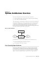
System Architecture Overview ..
27
27
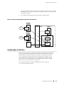
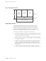
Packet Forwarding Engine Architecture .. .. .. .. .. .. .. .. .. .. .. .. .. .. .. .. .. .. .. .. .. . 27
Packet Forwarding Engine Components .. .. .. .. .. .. .. .. .. .. .. .. .. .. .. .. .. .. . 28
28
Data Flow Through the Packet Forwarding Engine . .. .. .. .. .. .. .. .. .. .. .. .. . 28
28
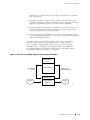
Routing Engine Architecture .. .. .. .. .. .. .. .. .. .. .. .. .. .. .. .. .. .. .. .. .. .. .. .. .. .. .. . 29
29
Routing Engine Functions .. .. .. .. .. .. .. .. .. .. .. .. .. .. .. .. .. .. .. .. .. .. .. .. .. .. . 30
30
Performing Initial Installation
Chapter 5
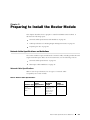
Preparing to Install the Router Module . .
35
Network Cable Specifications and Guidelines . .. .. .. .. .. .. .. .. .. .. .. .. .. .. .. .. .. . 35
35
Network Cable Specifications .. .. .. .. .. .. .. .. .. .. .. .. .. .. .. .. .. .. .. .. .. .. .. .. . 35
35
Fiber-Optic Cable Guidelines . .. .. .. .. .. .. .. .. .. .. .. .. .. .. .. .. .. .. .. .. .. .. .. .. . 36
36
Multimode and Single-Mode Fiber .. .. .. .. .. .. .. .. .. .. .. .. .. .. .. .. .. .. .. . 36
36
Attenuation and Dispersion . .. .. .. .. .. .. .. .. .. .. .. .. .. .. .. .. .. .. .. .. .. .. . 37
37
Calculating Power Budget and Margins. .. .. .. .. .. .. .. .. .. .. .. .. .. .. .. .. . 37
37
Cable Specifications for Routing Engine Management Ports . .. .. .. .. .. .. .. .. .. . 38
38
Preparing the Site.. .. .. .. .. .. .. .. .. .. .. .. .. .. .. .. .. .. .. .. .. .. .. .. .. .. .. .. .. .. .. .. .. . 38
38
Chapter 6
Unpacking the Router Module ..
39
Removing the Router Module from the Carton.. .. .. .. .. .. .. .. .. .. .. .. .. .. .. .. .. . 39
39
Chapter 7
Installing the Router Module . .
41
41
Tools and Parts Required . .. .. .. .. .. .. .. .. .. .. .. .. .. .. .. .. .. .. .. .. .. .. .. .. .. .. .. .. . 41
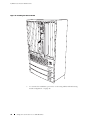
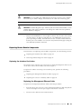
Sliding the Router Module into the CBX 500 Switch .. .. .. .. .. .. .. .. .. .. .. .. .. .. . 41
41
Chapter 8
Connecting Cables and Performing Initial Configuration ..
43
Tools and Parts Required .. .. .. .. .. .. .. .. .. .. .. .. .. .. .. .. .. .. .. .. .. .. .. .. .. .. .. .. .. . 43
43
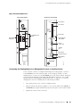
Connecting the Routing Engine to Management Devices .. .. .. .. .. .. .. .. .. .. .. . 43
43
Connecting the Routing Engine to a Network for Out-of-Band
Management .. .. .. .. .. .. .. .. .. .. .. .. .. .. .. .. .. .. .. .. .. .. .. .. .. .. .. .. .. .. .. .. .. . 44
44
Connecting the Routing Engine to a Management Console or Auxiliary
Device.. .. .. .. .. .. .. .. .. .. .. .. .. .. .. .. .. .. .. .. .. .. .. .. .. .. .. .. .. .. .. .. .. .. .. .. .. . 45
45
Installing the SFPs . .. .. .. .. .. .. .. .. .. .. .. .. .. .. .. .. .. .. .. .. .. .. .. .. .. .. .. .. .. .. .. .. . 46
46
Connecting Fiber-Optic Cables . .. .. .. .. .. .. .. .. .. .. .. .. .. .. .. .. .. .. .. .. .. .. .. .. .. . 47
47
Configuring the JUNOS Internet Software . .. .. .. .. .. .. .. .. .. .. .. .. .. .. .. .. .. .. .. . 48
48
Table of Contents
Table of Contents
Part 3
Maintaining Hardware, Replacing Parts, and
Troubleshooting
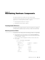
Chapter 9
Maintaining Hardware Components ..
55
Performing Routine Maintenance .. .. .. .. .. .. .. .. .. .. .. .. .. .. .. .. .. .. .. .. .. .. .. .. . 55
Maintaining the Router Module. .. .. .. .. .. .. .. .. .. .. .. .. .. .. .. .. .. .. .. .. .. .. .. .. .. . 55
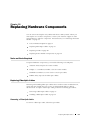
Chapter 10
Replacing Hardware Components. .
57
Tools and Parts Required .. .. .. .. .. .. .. .. .. .. .. .. .. .. .. .. .. .. .. .. .. .. .. .. .. .. .. .. .. . 57
Replacing Fiber-Optic Cables . .. .. .. .. .. .. .. .. .. .. .. .. .. .. .. .. .. .. .. .. .. .. .. .. .. .. . 57
Removing a Fiber-Optic Cable . .. .. .. .. .. .. .. .. .. .. .. .. .. .. .. .. .. .. .. .. .. .. .. . 57
Installing a Fiber-Optic Cable .. .. .. .. .. .. .. .. .. .. .. .. .. .. .. .. .. .. .. .. .. .. .. .. . 58
Replacing an SFP .. .. .. .. .. .. .. .. .. .. .. .. .. .. .. .. .. .. .. .. .. .. .. .. .. .. .. .. .. .. .. .. .. . 60
Removing an SFP . .. .. .. .. .. .. .. .. .. .. .. .. .. .. .. .. .. .. .. .. .. .. .. .. .. .. .. .. .. .. . 60
Installing an SFP .. .. .. .. .. .. .. .. .. .. .. .. .. .. .. .. .. .. .. .. .. .. .. .. .. .. .. .. .. .. .. . 61
Replacing Router Module Components .. .. .. .. .. .. .. .. .. .. .. .. .. .. .. .. .. .. .. .. .. . 63
Replacing the Interface Port Cables . .. .. .. .. .. .. .. .. .. .. .. .. .. .. .. .. .. .. .. .. . 63
Replacing the Management Ethernet Cable.. .. .. .. .. .. .. .. .. .. .. .. .. .. . 63
Replacing the Console or Auxiliary Cable .. .. .. .. .. .. .. .. .. .. .. .. .. .. .. . 64
Removing and Inserting a PC Card .. .. .. .. .. .. .. .. .. .. .. .. .. .. .. .. .. .. .. .. .. . 65
Removing the PC Card. .. .. .. .. .. .. .. .. .. .. .. .. .. .. .. .. .. .. .. .. .. .. .. .. .. . 65
Replacing the PC Card Adapter Flash Disk . .. .. .. .. .. .. .. .. .. .. .. .. .. .. . 66
Inserting the PC Card .. .. .. .. .. .. .. .. .. .. .. .. .. .. .. .. .. .. .. .. .. .. .. .. .. .. . 67
Chapter 11
Troubleshooting Hardware Components..
69
Overview of Troubleshooting Resources . .. .. .. .. .. .. .. .. .. .. .. .. .. .. .. .. .. .. .. .. . 69
Using the Command-Line Interface . .. .. .. .. .. .. .. .. .. .. .. .. .. .. .. .. .. .. .. .. . 69
LEDs . .. .. .. .. .. .. .. .. .. .. .. .. .. .. .. .. .. .. .. .. .. .. .. .. .. .. .. .. .. .. .. .. .. .. .. .. .. . 70
Hardware Alarm Messages . .. .. .. .. .. .. .. .. .. .. .. .. .. .. .. .. .. .. .. .. .. .. .. .. .. . 70
Getting Help from the Lucent Technical Assistance Center.. .. .. .. .. .. .. .. . 71
Part 4
Appendixes
Appendix A
Safety and Regulatory Compliance Information. .
75
Definition of Safety Warning Levels .. .. .. .. .. .. .. .. .. .. .. .. .. .. .. .. .. .. .. .. .. .. .. . 75
Safety Guidelines and Warnings .. .. .. .. .. .. .. .. .. .. .. .. .. .. .. .. .. .. .. .. .. .. .. .. .. . 76
General Safety Guidelines and Warnings.. .. .. .. .. .. .. .. .. .. .. .. .. .. .. .. .. .. . 77
Qualified Personnel Warning .. .. .. .. .. .. .. .. .. .. .. .. .. .. .. .. .. .. .. .. .. .. . 78
Restricted Access Area Warning .. .. .. .. .. .. .. .. .. .. .. .. .. .. .. .. .. .. .. .. . 79
Prevent Electrostatic Discharge Damage . .. .. .. .. .. .. .. .. .. .. .. .. .. .. .. . 80
Electrical Safety Guidelines and Warnings .. .. .. .. .. .. .. .. .. .. .. .. .. .. .. .. .. . 81
General Electrical Safety Guidelines .. .. .. .. .. .. .. .. .. .. .. .. .. .. .. .. .. .. . 81
Laser and LED Safety Guidelines and Warnings .. .. .. .. .. .. .. .. .. .. .. .. .. .. . 81
General Laser Safety Guidelines. .. .. .. .. .. .. .. .. .. .. .. .. .. .. .. .. .. .. .. .. . 82
Class 1 Laser Product Warning .. .. .. .. .. .. .. .. .. .. .. .. .. .. .. .. .. .. .. .. .. . 82
Class 1 LED Product Warning . .. .. .. .. .. .. .. .. .. .. .. .. .. .. .. .. .. .. .. .. .. . 83
Laser Beam Warning . .. .. .. .. .. .. .. .. .. .. .. .. .. .. .. .. .. .. .. .. .. .. .. .. .. .. . 83
Radiation From Open Port Apertures Warning .. .. .. .. .. .. .. .. .. .. .. .. . 84
Table of Contents
viii
IP/MPLS Router Module Hardware Guide
Maintenance and Operational Safety Guidelines and Warnings .. .. .. .. .. . 85
Battery Handling Warning . .. .. .. .. .. .. .. .. .. .. .. .. .. .. .. .. .. .. .. .. .. .. .. . 85
Product Disposal Warning . .. .. .. .. .. .. .. .. .. .. .. .. .. .. .. .. .. .. .. .. .. .. .. . 86
Agency Approvals.. .. .. .. .. .. .. .. .. .. .. .. .. .. .. .. .. .. .. .. .. .. .. .. .. .. .. .. .. .. .. .. .. . 87
Compliance Statements for EMC Requirements .. .. .. .. .. .. .. .. .. .. .. .. .. .. .. .. . 87
Canada. .. .. .. .. .. .. .. .. .. .. .. .. .. .. .. .. .. .. .. .. .. .. .. .. .. .. .. .. .. .. .. .. .. .. .. .. . 87
European Community .. .. .. .. .. .. .. .. .. .. .. .. .. .. .. .. .. .. .. .. .. .. .. .. .. .. .. .. . 87
United States .. .. .. .. .. .. .. .. .. .. .. .. .. .. .. .. .. .. .. .. .. .. .. .. .. .. .. .. .. .. .. .. .. . 88
Appendix B
Returning the Router Module . .
89
Tools and Parts Required . .. .. .. .. .. .. .. .. .. .. .. .. .. .. .. .. .. .. .. .. .. .. .. .. .. .. .. .. . 89
Return Procedure .. .. .. .. .. .. .. .. .. .. .. .. .. .. .. .. .. .. .. .. .. .. .. .. .. .. .. .. .. .. .. .. .. . 89
Locating the Serial Number .. .. .. .. .. .. .. .. .. .. .. .. .. .. .. .. .. .. .. .. .. .. .. .. .. . 90
Packing the Router Module for Shipment . .. .. .. .. .. .. .. .. .. .. .. .. .. .. .. .. .. . 90
Appendix C
Cable Connector Pinouts . .
93
RJ-45 Connector Pinouts for the MGMT Port .. .. .. .. .. .. .. .. .. .. .. .. .. .. .. .. .. .. . 93
DB-9 Connector Pinouts for the AUX/MODEM and CONSOLE Ports .. .. .. .. .. . 93
Part 5
Index
Index.. .. .. .. .. .. .. .. .. .. .. .. .. .. .. .. .. .. .. .. .. .. .. .. .. .. .. .. .. .. .. .. .. .. .. .. .. .. .. .. . 97
ix
Table of Contents
List of Figures
Figure 1: Front of Router Module . . . . . . . . . . . . . . . . . . . . . . . . . . . . . . . . . . . . . . . . . . . . . . . . . . . . . . . . . . . . . . . . 6
Figure 2: Rear of Router Module . . . . . . . . . . . . . . . . . . . . . . . . . . . . . . . . . . . . . . . . . . . . . . . . . . . . . . . . . . . . . . . . . 7
Figure 3: Routing Engine Management Ports . . . . . . . . . . . . . . . . . . . . . . . . . . . . . . . . . . . . . . . . . . . . . . . . . . 11
11
Figure 4: System Architecture. . . . . . . . . . . . . . . . . . . . . . . . . . . . . . . . . . . . . . . . . . . . . . . . . . . . . . . . . . . . . . . . . . . 27
Figure 5: Packet Forwarding Engine Components and Data Flow . . . . . . . . . . . . . . . . . . . . . . . . . . . . 29
Figure 6: Routing Engine Architecture. . . . . . . . . . . . . . . . . . . . . . . . . . . . . . . . . . . . . . . . . . . . . . . . . . . . . . . . . . 30
Figure 7: Control Packet Handling: Routing and Forwarding Table Updates. . . . . . . . . . . . . . . . . . 31
Figure 8: Installing the Router Module. . . . . . . . . . . . . . . . . . . . . . . . . . . . . . . . . . . . . . . . . . . . . . . . . . . . . . . . . . 42
Figure 9: Routing Engine Ethernet Cable Connector . . . . . . . . . . . . . . . . . . . . . . . . . . . . . . . . . . . . . . . . . . 44
Figure 10: Router Module Ports . . . . . . . . . . . . . . . . . . . . . . . . . . . . . . . . . . . . . . . . . . . . . . . . . . . . . . . . . . . . . . . . . 45
Figure 11: Console and Auxiliary Serial Port Connector . . . . . . . . . . . . . . . . . . . . . . . . . . . . . . . . . . . . . . . 46
Figure 12: Installing an SFP in a Gigabit Ethernet Slot. . . . . . . . . . . . . . . . . . . . . . . . . . . . . . . . . . . . . . . . . 46
Figure 13: Small Form-Factor Pluggable (SFP) . . . . . . . . . . . . . . . . . . . . . . . . . . . . . . . . . . . . . . . . . . . . . . . . . 60
Figure 14: Installing a Replacement SFP in a Gigabit Ethernet Slot . . . . . . . . . . . . . . . . . . . . . . . . . . . 62
Figure 15: Routing Engine Ethernet Cable Connector . . . . . . . . . . . . . . . . . . . . . . . . . . . . . . . . . . . . . . . . . 64
Figure 16: Router Module Ports . . . . . . . . . . . . . . . . . . . . . . . . . . . . . . . . . . . . . . . . . . . . . . . . . . . . . . . . . . . . . . . . . 64
Figure 17: Console and Auxiliary Serial Port Connector . . . . . . . . . . . . . . . . . . . . . . . . . . . . . . . . . . . . . . . 65
Figure 18: Removing the PC Card . . . . . . . . . . . . . . . . . . . . . . . . . . . . . . . . . . . . . . . . . . . . . . . . . . . . . . . . . . . . . . 66
Figure 19: Inserting the PC Card Flash Disk. . . . . . . . . . . . . . . . . . . . . . . . . . . . . . . . . . . . . . . . . . . . . . . . . . . . 67
Figure 20: Inserting the PC Card. . . . . . . . . . . . . . . . . . . . . . . . . . . . . . . . . . . . . . . . . . . . . . . . . . . . . . . . . . . . . . . . 67
Figure 21: Placing a Component into an Electrostatic Bag . . . . . . . . . . . . . . . . . . . . . . . . . . . . . . . . . . . . 81
List of Figures
x
IP/MPLS Router Module Hardware Guide
xi
List of Figures
List of Tables
Table 1: Juniper Networks Technical Documentation . . . . . . . . . . . . . . . . . . . . . . . . . . . . . . . . . . . . . . . . .xvi
Table 2: Lucent Technologies Technical Documentation . . . . . . . . . . . . . . . . . . . . . . . . . . . . . . . . . . . . xviii
Table 3: Router Module Physical Specifications . . . . . . . . . . . . . . . . . . . . . . . . . . . . . . . . . . . . . . . . . . . . . . . . . 8
Table 4: States for Routing Engine LEDs. . . . . . . . . . . . . . . . . . . . . . . . . . . . . . . . . . . . . . . . . . . . . . . . . . . . . . . . . 9
Table 5: Features and Specifications for OC12/STM4 ATM Ports . . . . . . . . . . . . . . . . . . . . . . . . . . . . . . 12
Table 6: Optical Interface Support for OC12/STM4 ATM Ports. . . . . . . . . . . . . . . . . . . . . . . . . . . . . . . . . 13
Table 7: Features and Specifications for Gigabit Ethernet Ports . . . . . . . . . . . . . . . . . . . . . . . . . . . . . . . 14
Table 8: Optical Interface Support for Gigabit Ethernet Ports . . . . . . . . . . . . . . . . . . . . . . . . . . . . . . . . . 15
Table 9: Network Cable Specifications. . . . . . . . . . . . . . . . . . . . . . . . . . . . . . . . . . . . . . . . . . . . . . . . . . . . . . . . . . 35
Table 10: Cable Specifications for Routing Engine Management Ports. . . . . . . . . . . . . . . . . . . . . . . . 38
Table 11: States for Routing Engine LEDs. . . . . . . . . . . . . . . . . . . . . . . . . . . . . . . . . . . . . . . . . . . . . . . . . . . . . . . 70
Table 12: RJ-45 Connector Pinout. . . . . . . . . . . . . . . . . . . . . . . . . . . . . . . . . . . . . . . . . . . . . . . . . . . . . . . . . . . . . . . 93
Table 13: DB-9 Connector Pinout . . . . . . . . . . . . . . . . . . . . . . . . . . . . . . . . . . . . . . . . . . . . . . . . . . . . . . . . . . . . . . . 94
List of Tables
xii
IP/MPLS Router Module Hardware Guide
xiii
List of Tables
About This Manual
This preface provides the following guidelines for using the IP/MPLS Router Module
Hardware Guide:
Objectives on page xiv
Audience on page xv
Document Organization on page xv
Documentation Conventions on page xv
List of Technical Publications on page xvi
Documentation Feedback on page xix
How to Request Support on page xix
Objectives
This manual describes hardware installation and basic troubleshooting procedures
for the Lucent Technologies IP/MPLS Router Module. It explains how to prepare
your site for router module installation, unpack and install the hardware, power
on the router module, perform initial software configuration, and perform routine
maintenance. After completing the installation and basic configuration procedures
covered in this manual, refer to the JUNOS Internet software configuration guides
for information about further JUNOS software configuration.
To obtain additional information about the IP/MPLS router module—either
corrections to information in this manual or information that might have been
omitted from this manual—refer to the hardware release notes.
To obtain the most current version of this manual, the most current version of the
hardware release notes, and other technical documentation for the IP/MPLS router
module, refer to the product documentation page on the Lucent Technologies Web
site, which is located at http://www.lucent.com.
To order printed copies of this manual, use the following URL to access the Lucent
Bookstore:
http://www.lucentdocs.com
Objectives
xiv
IP/MPLS Router Module Hardware Guide
To obtain the most current version of other Juniper Networks technical
documentation, refer to the product documentation page on the Juniper Networks
Web site, which is located at http://www.juniper.net.
Audience
This manual is designed for network administrators who are installing and
maintaining a Juniper Networks router, or preparing a site for router installation. It
assumes a broad understanding of networks in general, the Internet in particular,
networking principles, and network configuration. Any detailed discussion of these
concepts is beyond the scope of this manual.
Document Organization
This manual is divided into several parts:
Part 1, "Product Overview," provides an overview of the router
module, describing its hardware components, the JUNOS Internet
software, and the system architecture.
Part 2, "Performing Initial Installation," describes how to prepare your
site for router module installation, and how to unpack, install, and power
on the router module. It describes requirements and specifications
for the installation site, power source, wiring, and cabling. It also
provides detailed safety guidelines and warnings.
Part 3, "Maintaining Hardware, Replacing Parts, and Troubleshooting,"
describes how to maintain, replace, and troubleshoot the router module.
This manual also contains a complete index.
Documentation Conventions
General Conventions
This manual uses the following text conventions:
Router and router component labels are shown in a sans serif font. In the
following example, ETHERNET is the label for the Ethernet management port
on the router:
The 10/100-Mbps Ethernet RJ-45 connector is used for out-of-band
management of the router and is labeled ETHERNET.
Statements, commands, filenames, directory names, IP addresses, and
configuration hierarchy levels are shown in a sans serif font. In the following
example, stub is a statement name and [edit protocols ospf area area-id ] is a
configuration hierarchy level:
xv
Documentation Conventions
About This Manual
To configure a stub area, include the stub statement at the [edit protocols ospf
area area-id ] hierarchy level.
In examples, text that you type literally is shown in bold. In the following
example, you type the words show chassis alarms :
For example, you can use the following command to get information about
the source of an alarm condition:
user@host> show chassis alarms
Notes, Cautions, and Warnings
Notes, cautions, and warnings are denoted by the following symbols:
NOTE: A note indicates information that might be helpful in a particular situation or
that might otherwise be overlooked.
CAUTION: A caution indicates a situation that requires careful attention. Failure to
observe a cautionary note could result in minor injury or discomfort to yourself, or
serious damage to the router.
WARNING: A warning indicates a potentially dangerous situation. Failure to follow
the guidelines in a warning could result in severe injury or death.
List of Technical Publications
Table 1 lists the software and hardware books for Juniper Networks J-series,
M-series, and T-series routers and describes the contents of each book. Table 2
lists the software and hardware books from Lucent Technologies for installing
and managing the CBX 500 switch.
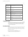
Table 1: Juniper Networks Technical Documentation
Book
Description
JUNOS Internet Software for J-series, M-series, and T-series Routing Platforms
Configuration Guides
Feature Guide
Provides a detailed explanation and configuration examples for
several of the most complex features in the JUNOS software.
List of Technical Publications
xvi
IP/MPLS Router Module Hardware Guide
Book
Description
System Basics
Provides an overview of the JUNOS software and describes how to
install and upgrade the software. This manual also describes how
to configure system management functions and how to configure
the chassis, including user accounts, passwords, and redundancy.
Network Interfaces and
Class of Service
Provides an overview of the network interface and class-of-service
functions of the JUNOS software and describes how to configure
the network interfaces on the router.
MPLS Applications
Provides an overview of traffic engineering concepts and describes
how to configure traffic engineering protocols.
Multicast Protocols
Provides an overview of multicast concepts and describes how to
configure multicast routing protocols.
Network Management
Provides an overview of network management concepts and
describes how to configure various network management features,
such as SNMP, accounting options, and cflowd.
Policy Framework
Provides an overview of policy concepts and describes how to
configure routing policy, firewall filters, and forwarding options.
Routing Protocols
Provides an overview of routing concepts and describes how to
configure routing, routing instances, and unicast routing protocols.
Services Interfaces
Provides an overview of the services interfaces functions of the
JUNOS software and describes how to configure the services
interfaces on the router.
VPNs
Provides an overview and describes how to configure Layer 2 and
Layer 3 virtual private networks (VPNs), virtual private LAN service
(VPLS), and Layer 2 circuits. Provides configuration examples.
JUNOS References
Network and Services
Interfaces Command
Reference
Describes the JUNOS Internet software operational mode
commands you use to monitor and troubleshoot network and
services interfaces on Juniper Networks routing platforms.
Protocols, Class of Service,
and System Basics
Command Reference
Describes the JUNOS Internet software operational mode
commands you use to monitor and troubleshoot most aspects of
Juniper Networks routing platforms
System Log Messages
Reference
Describes how to access and interpret system log messages
generated by JUNOS software modules and provides a reference
page for each message.
JUNOScript API Documentation
JUNOScript API Guide
Describes how to use the JUNOScript application programming
interface (API) to monitor and configure Juniper Networks routers.
JUNOScript API
Configuration Reference
Provides reference pages for the configuration tags in the
JUNOScript API.
JUNOScript API Operational
Reference
Provides reference pages for the operational tags in the JUNOScript
API.
JUNOS Comprehensive Index and Glossary
Comprehensive Index and
Glossary
Hardware Documentation
xvii
List of Technical Publications
Provides a complete index of all JUNOS Internet software books
and the JUNOScript API Guide. Also provides a comprehensive
glossary.
About This Manual
Book
Description
Hardware Guide
Describes how to install, maintain, and troubleshoot routers and
router components. Each platform has its own hardware guide.
PIC Guide
Describes the router Physical Interface Cards (PICs). Each router
platform has its own PIC guide.
JUNOScope Documentation
JUNOScope Software User
Guide
Describes the JUNOScope software graphical user interface (GUI),
how to install and administer the software, and how to use the
software to manage router configuration files and monitor router
operations.
J-series Services Router Documentation
J-series Services Router
User Guide
Contains instructions for installing, configuring, and managing a
J-series Services Router. The guide explains how to prepare your
site for installation, unpack and install the hardware, power on the
router, configure secure routing, monitor network operations, and
perform routine maintenance.
Release Notes
JUNOS Internet Software
Release Notes
Provide a summary of new features for a particular software
release. Software release notes also contain corrections and
updates to published JUNOS and JUNOScript manuals, provide
information that might have been omitted from the manuals, and
describe upgrade and downgrade procedures.
Hardware Release Notes
Describe the available documentation for the router platform
and summarize known problems with the hardware and
accompanying software. Each platform has its own release notes.
JUNOScope Software
Release Notes
Contain corrections and updates to the published JUNOScope
manual, provide information that might have been omitted from
the manual, and describe upgrade and downgrade procedures.
JUNOS for J-series Services
Routers Release Notes
Briefly describe Services Router features, identify known software
problems, and provide upgrade and downgrade instructions
Table 2: Lucent Technologies Technical Documentation
Book
Description
CBX 500 Multiservice
WAN Switch Hardware
Installation Guide
Describes how to install and set up the CBX 500 switch hardware,
replace hardware modules, and interpret LED status indicators.
Network Management
Station Installation Guide
Describes how to install NavisCore network management software
and supporting applications on the Network Management Station
(NMS). You manage a CBX 500 switch through the NMS NavisCore
software.
Getting Started User’s Guide
Describes how to configure and manage NavisCore, network maps,
and Lucent switches. It also describes how to add third-party
objects to the map and access them through NavisCore.
Switch Module
Configuration Guide
Describes the processor and input/output modules (IOMs) on the
switch, and the configuration of physical ports, timing, and other
attributes through NavisCore.
List of Technical Publications
xviii
IP/MPLS Router Module Hardware Guide
Book
Description
Frame Relay Services
Configuration Guide for
CBX 3500, CBX 500, and
B-STDX 9000
Describes how to configure frame relay WAN services on the
supported switch platforms.
ATM Services Configuration
Guide for CBX 3500, CBX
500, GX 550, and B-STDX
9000
Describes how to configure ATM WAN services on the supported
switch platforms.
IP Services Configuration
Guide for CBX 500 and
B-STDX 9000
Describes how to configure IP WAN services on the supported
switch platforms.
Console Command User’s
Reference
Contains reference lists and describes the switch console
commands.
Diagnostics User’s Guide
Describes how to monitor and diagnose problems in your Navis
EMS-CBGX switch network.
Navis EMS-CBGX
Installation and
Administration Guide
Describes prerequisite tasks, hardware and software requirements,
and instructions for installing and upgrading Solaris and Navis
EMS-CBGX on the NMS.
Navis EMS-CBGX Graphical
User Interface Guide
Describes how to start the Navis EMS-CBGX client on Windows
and Solaris. It also provides a description of the Navis EMS-CBGX
window components, how to access network and map
configuration options, and instructions for customizing Navis
EMS-CBGX.
Getting Started User’s Guide
Describes how to configure and manage Navis EMS-CBGX,
network maps, and Lucent switches. It also describes how to add
third-party objects to the map and access them through Navis
EMS-CBGX.
Documentation Feedback
We are always interested in hearing from our customers. Please let us know what
you like and do not like about the Juniper Networks documentation, and let us
know of any suggestions you have for improving the documentation. Also, let
us know if you find any mistakes in the documentation. Send your feedback
to [email protected].
How to Request Support
The Lucent Technical Assistance Center (TAC) is available to assist you with any
problems encountered while you use this Lucent product. Log on to the Customer
Support Web site to obtain telephone numbers for the Lucent TAC in your region:
http://www.lucent.com/support
Juniper Networks maintains this hardware guide. For
documentation issues, fill out the bug report form located at
http://www.juniper.net/techpubs/docbug/docbugreport.html
xix
How to Request Support
Part 1
Product Overview
System Overview on page 3
Hardware Component Overview on page 5
JUNOS Internet Software Overview on page 17
System Architecture Overview on page 27
Product Overview
1
2
Product Overview
Chapter 1
System Overview
This chapter provides an overview of the IP/MPLS router module, discussing the
following topics:
System Description on page 3
Safety Requirements, Warnings, and Guidelines on page 3
System Description
The IP/MPLS router module is a complete routing system that provides ATM,
Ethernet, and IP services for large networks and network applications, such
as those supported by Internet service providers (ISPs). Application-specific
integrated circuits (ASICs), a definitive part of the router module design,
enable the router module to forward data at the high speeds demanded by
current network media. The IP/MPLS router module is designed exclusively
for installation in the Lucent Technologies CBX 500 switch.
The router module provides two Gigabit Ethernet ports and two
OC12/STM4 ATM ports.
The router module architecture cleanly separates control operations from
packet forwarding operations, which helps to eliminate processing and traffic
bottlenecks. The router module performs control operations and runs JUNOS
Internet software to handle routing protocols, traffic engineering, policy, policing,
monitoring, and configuration management. Forwarding operations in the
router module are performed by the packet forwarding engine, which consists
of hardware, including ASICs, designed by Juniper Networks.
Safety Requirements, Warnings, and Guidelines
To avoid harm to yourself or the router module as you install and maintain it, you
must follow the guidelines for working with and near electrical equipment, as well
as the safety procedures for working with Internet routers. For a discussion of how
to make the installation site a safe environment, see “Preparing to Install the Router
Module” on page 35. For a list of safety warnings, see “Safety and Regulatory
Compliance Information” on page 75 and particularly “Electrical Safety Guidelines
and Warnings” on page 81. However, providing an exhaustive set of guidelines
for working with electrical equipment is beyond the scope of this manual.
Safety Requirements, Warnings, and Guidelines
3
IP/MPLS Router Module Hardware Guide
4
Safety Requirements, Warnings, and Guidelines
Chapter 2
Hardware Component Overview
This chapter provides an overview of the hardware components in the IP/MPLS
router module:
Physical Specifications on page 5
Packet Forwarding Engine on page 8
Routing Engine on page 8
Router Module Interface Ports on page 11
Physical Specifications
The router module is a rigid sheet metal structure that houses the other hardware
components. The router module is 16.0 in. (40.6 cm) high and 13.1 in. (33.3 cm)
deep. The two mounting ears (one each on the top and bottom) extend the height
to 17.2 in. (43.7 cm). The width of 2.1 in. (5.3 cm) enables side-by-side installation
of six IP/MPLS router modules in a single CBX 500 switch. You can install a router
module in any two adjacent CBX 500 slots except the leftmost slot (slot 3).
The router module is hot-insertable (this means that you do not need to power
off the switch first). However, it is not hot-removable—before you remove it
from the switch, you must shut it down from the JUNOS software command
line or by using the offline/online button on the front panel.
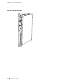
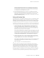
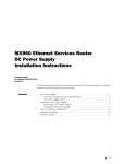
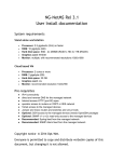
Figure 1 and Figure 2 show two views of the router module.
Physical Specifications
5
IP/MPLS Router Module Hardware Guide
Figure 1: Front of Router Module
IP/MPLS Rou
ter Module
STM-4/OC
-12
ATM2 IQ SMF
GIGABIT
ENET
TX
STATUS
PORT
0/0/0
RX
PORT
0/0/1
TX
RX
PORT 1/0/1
STATUS
TX
RX
PORT 1/0/1
STATUS
CAUT
ION
DO NO
T
INSTAL
L
IN SL
OT #3
RESE
T
SOFT
WA
VERS RE
ION
LABE
L
THIS
SIDE
FAILE
D
POWE
R
AUX/
MODE
M
MGMT
OFFL
ONLI INE/
NE
6
Physical Specifications
HDD
MAST
ER
OLE
g002117
CONS
PC
CARD
Hardware Component Overview
g002118
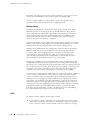
Figure 2: Rear of Router Module
WARNING: Static electricity can damage the router module. Before handling the
router module, put on the antistatic wrist strap that is provided in the router
module accessory kit, and connect it to the grounding jack located on the front
of the switch. For more information about using the wrist strap, see the CBX 500
Multiservice WAN Switch Hardware Installation Guide from Lucent Technologies.
For further safety information, see “Safety and Regulatory Compliance Information”
on page 75.
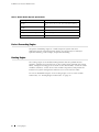
Table 3 summarizes physical specifications for the router module.
Physical Specifications
7
IP/MPLS Router Module Hardware Guide
Table 3: Router Module Physical Specifications
Description
Value
Height
16.0 in. (40.6 cm); 17.2 in. (43.7 cm) with mounting
ears
Width
2.1 in. (5.3 cm)
Depth
13.1 in. (33.3 cm)
Weight, maximum configuration
13.6 lb (6.2 kg)
Thermal output
256 BTU
Packet Forwarding Engine
The packet forwarding engine is a multicomponent system that uses
application-specific integrated circuits (ASICs) to perform Layer 2 and Layer
3 packet switching, route lookups, and packet forwarding.
Routing Engine
The routing engine is an Intel-based PCI platform that runs JUNOS Internet
software. Software processes that run on the routing engine maintain the routing
tables, manage the routing protocols used on the router module, control the router
module’s interfaces, control other router module components, and provide the
interface for system management and user access to the router module.
For a more detailed description of the routing engine’s role in router module
architecture, see “Routing Engine Architecture” on page 29.
8
Routing Engine
Hardware Component Overview
Routing Engine Components
The routing engine is a two-board system with the following components:
CPU—Runs JUNOS Internet software to maintain the router module’s routing
tables and routing protocols. It has a Pentium-class processor.
SDRAM—Provides 768 MB of storage for the routing and forwarding tables
and for other routing engine processes.
Internal flash disk—Provides 256 MB of primary storage. It can accommodate
software images, configuration files, and microcode.
Hard disk—Provides secondary storage for log files and memory dumps, and
can reboot the system if the flash disk fails.
PC card slot—Accepts a removable PC card, which stores software images
for system upgrades.
Four LEDs—A green LED labeled HDD, a blue LED labeled MASTER, a red LED
labeled FAILED, and a green LED labeled POWER indicate routing engine status.
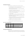
Table 4 describes the LED states.
Interfaces for out-of-band management access—Provide information about
routing engine status to devices (console, laptop, or terminal server) that can
be attached to access ports located on the router module.
I2C/EEPROM—Stores the serial number of the routing engine.
Reset button—Reboots the routing engine when pressed.
Offline/online button—Powers off the routing engine when pressed.
Table 4: States for Routing Engine LEDs
Label
Color
State
Description
HDD
Green
Blinking
There is read/write activity on the PC card.
MASTER
Blue
On steadily
Routing engine is functioning as master. On an
IP/MPLS router module, this LED is always lit.
FAILED
Red
On steadily
Routing engine is not operational.
POWER
Green
On steadily
Routing engine is running normally.
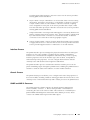
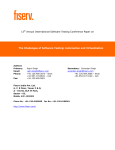
Routing Engine Management Ports
On the bottom half of the router module’s faceplate are ports for connecting the
routing engine to one or more external devices on which system administrators can
issue JUNOS command-line interface (CLI) commands to manage the routing engine.
Routing Engine
9
IP/MPLS Router Module Hardware Guide
The ports are labeled and function as follows:
CONSOLE—Connects the routing engine to a system console through an RS-232
(EIA-232) serial cable.
AUX/MODEM— Connects the routing engine to a laptop, modem, or other
auxiliary device through an RS-232 (EIA-232) serial cable.
MGMT—Connects the routing engine through an Ethernet connection to a
management LAN (or any other device that plugs into an Ethernet connection)
for out-of-band management. The port uses an autosensing RJ-45 connector to
support both 10- and 100-Mbps connections. Two small LEDs on the right
edge of the port indicate the connection in use: the amber LED flashes in
correspondence with activity for a 10-Mbps connection, and the green LED
flashes in correspondence with activity for a 100-Mbps connection.
For information about the pinouts for the connectors, see “Cable
Connector Pinouts” on page 93.
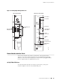
Figure 3 shows the routing engine management ports.
10
Routing Engine
Hardware Component Overview
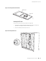
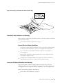
Figure 3: Routing Engine Management Ports
Top of router module
Bottom of router module
Reset button
RESET
PC card slot
SOFTWARE
VERSION
LABEL
THIS
SIDE
IP/MPLS Router Module
STM-4/OC-12
ATM2 IQ SMF
GIGABIT
ENET
TX
RX
PC
CARD
STATUS
PORT
0/0/0
PORT
0/0/1
OC12/STM4
ATM ports
Eject button
Gigabit Ethernet
ports
TX
PORT 1/0/1
STATUS
FAILED
POWER
RX
TX
HDD
MASTER
Routing Engine
status LEDs
RX
CONSOLE
System
console port
PORT 1/0/0
STATUS
R
AUX/
MODEM
MGMT
OFFLINE/
ONLINE
Auxiliary
port
Out-of-band
management port
Offline/Online
button
g002123
CAUTION
DO NOT
INSTALL
IN SLOT #3
Router Module Interface Ports
This section describes the features, specifications, and optical interface
support of the router module interface ports (OC12/STM4 ATM and Gigabit
Ethernet). This section also describes the small form-factor pluggables (SFPs)
that are supported by the Gigabit Ethernet ports.
OC12/STM4 ATM Ports
The following tables describe the features, specifications, and optical
interface support for the two OC12/STM4 ATM ports.
Router Module Interface Ports
11
IP/MPLS Router Module Hardware Guide
Table 5: Features and Specifications for OC12/STM4 ATM Ports
Description
Two OC12/STM4 ATM ports
Intelligent queuing (IQ) supports fine-grained queuing per logical interface
Conforms to ANSI T1.105-1991 and T1E1.2/93-020R1
ATM standards compliant
Alarm and event counting and detection
Compatible with well-known ATM switches
ATM switch ID, which displays the switch IP address and local interface name of
the adjacent Fore ATM switches
Hardware features
ASIC-based packet segmentation and reassembly (SAR) management and output
port queuing
64-MB SDRAM memory for ATM SAR
Packet buffering, Layer 2 parsing
Software features
Multiprotocol Label Switching (MPLS) circuit cross-connect for leveraging ATM access
networks
User-configurable virtual circuit (VC) and virtual path (VP) support
Support for idle cell or unassigned cell transmission
OAM Fault Management processes Alarm Indication Signal (AIS), Remote Defect
Indicator (RDI), and loop cells
Point-to-point and point-to-multipoint mode Layer 2 counters per VC and per VP
Local and remote loopback
ATM Inverse ARP, which enables routers to automatically learn the IP address of
the router on the far end of an ATM PVC
Simple Network Management Protocol (SNMP):
Management Information Base (MIB) 2 (RFC 1213)
ATM MIB (RFC 1695)
SONET MIB
Unspecified bit rate (UBR), non-real-time variable bit rate (VBR), and constant bit
rate (CBR) traffic shaping
Per-VC or per-VP traffic shaping
Support for F4 OAM cells
Support for 16-bit VCI range
Cables and connectors
12
Duplex SC/PC connector (RX and TX)
Router Module Interface Ports
Hardware Component Overview
LEDs
One tricolor LED per port:
Off—Not enabled
Green—Online with no alarms or failures
Amber—Online with alarms for remote failures
Red—Active with a local alarm; router has detected a failure
Alarm Indication Signal (AIS-L, AIS-P)
Alarms, errors, and
events
Bit Error Rate Signal Degrade (BERR-SD), Bit Error Rate Signal Fail (BERR-SF)
Bit Interleaved Parity Errors B1, B2, B3 (CV-S, CV-L, CV-P)
Errored Seconds (ES-S, ES-L, ES-P), Far-end Bit Errors REI-L, REI-P (CV-LFE, CV-PFE),
Far-end Errored Seconds (ES-LFE, ES-PFE), Far-end Severely Errored Seconds
(SES-LFE, SES-PFE), Far-end Unavailable Seconds (UAS-LFE, UAS-PFE)
Loss of Cell Delineation (LoC), Loss of Frame (LoF), Loss of Pointer (LoP-P), Loss of
Signal (LoS)
Payload Mismatch (PLM-P), Payload Unequipped (UNEQ-P)
Remote Defect Indication (RDI-L, RDI-P)
Severely Errored Framing (SEF), Severely Errored Framing Seconds (SEFS-S), Severely
Errored Seconds (SES-S, SES-L, SES-P), Unavailable Seconds (UAS-L, UAS-P)
Table 6: Optical Interface Support for OC12/STM4 ATM Ports
Specification
Value
Optical interface
Single-mode, intermediate reach (Bellcore GR-253 compliant) with SC/PC duplex connector
(maximum distance 9.3 miles/15 km)
Wavelength
1274 through 1356 nm
Average launch power
–15 through –8 dBm
Receiver saturation
–8 dBm
Receiver sensitivity
–28 dBm
Gigabit Ethernet Ports
The following tables describe the features, specifications, and optical
interface support for the two Gigabit Ethernet ports.
Router Module Interface Ports
13
IP/MPLS Router Module Hardware Guide
Table 7: Features and Specifications for Gigabit Ethernet Ports
Description
Two Gigabit Ethernet ports
Support large Ethernet frame sizes for more efficient throughput across the intra-POP
network
Hardware features
High-performance throughput on all ports at speeds up to 1 Gbps
Autonegotiation between Gigabit Ethernet circuit partners
Full-duplex mode
Maximum transmission units (MTUs) of up to 9192 bytes
Software features
Virtual Router Redundancy Protocol (VRRP) support
802.1Q virtual LANs (VLANs) support
64 source MAC filters per VLAN and 1024 source MAC filters per port
960 destination MAC filters per port
MAC accounting and policing—Dynamic local address learning of source MAC
addresses
Cables and connectors
You can use 1000Base-T, 1000Base-SX, 1000Base-LX, and 1000Base-LH SFPs.
SX, LX, and LH small form factor pluggable transceivers (SFPs):
Duplex LC/PC connector (RX and TX)
1000Base-T SFPs:
Connector: Four-pair, category 5 shielded twisted-pair connectivity through
an RJ-45 connector
Pinout: MDI crossover
Length: 328-ft/100-m
LEDs
Port LEDs, one pair per port:
RX (link)—If green, the port is online; if there is no light, the port is down
TX (activity)—If flashing green, the port is receiving data; if there is no light, the port
might be on, but is not receiving data
Status LEDs, one bicolor:
Off—port is not enabled
Green—port is operating normally
Red—port has an error or failure
14
Router Module Interface Ports
Hardware Component Overview
Table 8: Optical Interface Support for Gigabit Ethernet Ports
PIC Type
SX Transceiver
LX Transceiver
LH Transceiver
Optical interface
656-ft/200-m
reach on
62.5/125-micrometer
multimode fiber
(MMF)
6.2-mile/10-km reach
on 9/125-micrometer
single-mode fiber
(SMF)
49.5-mile/70-km
reach on
8.2-micrometer SMF
1640-ft/500-m
reach on
50/125-micrometer
MMF
1804.5-ft/550-m
reach on
62.5/125 and
50/125-micrometer
MMF
Wavelength
830 through 860 nm
1275 through 1350
nm
1480 through 1580
nm
Average launch power
–9.5 through –4 dBm
–9.5 through –3 dBm
–3 through +3 dBm
Receiver saturation
–3 dBm
–3 dBm
–3 dBm
Receiver sensitivity
–18 dBm
–20.5 dBm
–23 dBm
SFPs
SFPs are optical transceivers that you can install in and remove from the router
module. Each Gigabit Ethernet port supports SX, LX, LH, and 1000Base-T SFPs. The
router module includes two SFPs of either the SX, LX, or LH type depending on
the configuration that you ordered. (1000Base-T SFPs are not provided.)
Router Module Interface Ports
15
IP/MPLS Router Module Hardware Guide
16
Router Module Interface Ports
Chapter 3
JUNOS Internet Software Overview
The JUNOS Internet software is especially designed for the large production
networks typically supported by Internet service providers (ISPs). It incorporates
Internet Protocol (IP) routing software and software for management of interfaces,
networks, and the router module.
The JUNOS Internet software runs on the routing engine. The software consists
of processes that support Internet routing protocols, control the router module’s
interfaces and the router module itself, and provide an interface for system
management. The processes run on top of a kernel that coordinates the
communication among processes and has a direct link to the packet forwarding
engine software.
Use the JUNOS Internet software to configure the routing protocols that run on
the router module and the properties of router module interfaces. After you have
activated a software configuration, use the JUNOS Internet software to monitor the
protocol traffic passing through the router module and to troubleshoot protocol
and network connectivity problems.
For additional information about the JUNOS Internet software, including its security
features and a list of the industry standards it supports, see the JUNOS System Basics
Configuration Guide. For complete information about configuring the software
(including examples), see the JUNOS Internet software configuration guides.
NOTE: The router module supports Release 7.0 and later versions of the JUNOS
Internet software.
This chapter discusses the following topics:
Routing Engine Software Components on page 18
Tools for Accessing and Configuring the Software on page 24
Tools for Monitoring the Software on page 24
Upgrading Software on page 25
Router Module Interface Ports
17
IP/MPLS Router Module Hardware Guide
Routing Engine Software Components
The routing engine software consists of several software processes that control
router module functions and a kernel that coordinates communication among the
processes, as described in the following sections:
Routing Protocol Process on page 18
VPNs on page 22
Interface Process on page 23
Chassis Process on page 23
SNMP and MIB II Processes on page 23
Management Process on page 24
Routing Engine Kernel on page 24
Routing Protocol Process
The JUNOS software routing protocol process controls the routing protocols that run
on the router module. The routing protocol process starts all configured routing
protocols and handles all routing messages. It consolidates the routing information
learned from all routing protocols into common routing tables. From this routing
information, the routing protocol process determines the active routes to network
destinations and installs these routes in the routing engine’s forwarding table.
Finally, the routing protocol process implements the routing policies you specify,
which determine how routing information is transferred between the routing
protocols and the routing table.
This section discusses the following topics:
IPv4 Routing Protocols on page 18
IPv6 Routing Protocols on page 20
Routing and Forwarding Tables on page 21
Routing Policy on page 22
For complete information about routing concepts, see the JUNOS
Internet software configuration guides.
IPv4 Routing Protocols
The JUNOS Internet software implements full IP routing functionality,
providing support for IP version 4 (IPv4). The routing protocols are fully
interoperable with existing IP routing protocols and provide the scale and
18
Routing Engine Software Components
JUNOS Internet Software Overview
control necessary for the Internet core. The software provides support for
the following routing and traffic engineering protocols:
Unicast routing protocols
BGP—Border Gateway Protocol, version 4, is an Exterior Gateway Protocol
(EGP) that guarantees loop-free exchange of routing information between
routing domains (also called autonomous systems). BGP, in conjunction
with JUNOS routing policy, provides a system of administrative checks and
balances that can be used to implement peering and transit agreements.
ICMP—Internet Control Message Protocol router discovery is a method
that hosts can use to discover the addresses of operational routers on a
subnet.
IS-IS—Intermediate System-to-Intermediate System is a link-state interior
gateway protocol (IGP) for IP networks that uses the shortest-path-first
algorithm (SPF algorithm, also called the Dijkstra algorithm) to determine
routes.
OSPF—Open Shortest Path First, version 2, is an IGP developed for
IP networks by the Internet Engineering Task Force (IETF). OSPF is
a link-state protocol that makes routing decisions based on the SPF
algorithm.
RIP—Routing Information Protocol, version 2, is an IGP for IP networks
based on the Bellman-Ford algorithm. RIP is a distance-vector protocol.
RIP dynamically routes packets between a subscriber and a service
provider without the subscriber having to configure BGP or to participate
in the service provider’s IGP discovery process.
Multicast routing protocols
DVMRP—Distance Vector Multicast Routing Protocol is a dense-mode
(flood-and-prune) multicast routing protocol.
IGMP—Internet Group Management Protocol, versions 1 and 2, is used
to manage membership in multicast groups.
MSDP—Multicast Source Discovery Protocol enables multiple PIM sparse
mode domains to be joined. A rendezvous point (RP) in a PIM sparse
mode domain has a peering relationship with an RP in another domain,
thereby discovering multicast sources from other domains.
PIM sparse mode and dense mode—Protocol-Independent Multicast is a
multicast routing protocol used to route traffic to multicast groups that
might span wide-area and interdomain internetworks. In PIM sparse
Routing Engine Software Components
19
IP/MPLS Router Module Hardware Guide
mode, routers explicitly join and leave multicast groups. PIM dense
mode is a flood-and-prune protocol.
SAP/SDP—Session Announcement Protocol and Session Description
Protocol handle conference session announcements.
MPLS application protocols
LDP—Label Distribution Protocol provides a mechanism for distributing
labels in nontraffic-engineered applications. LDP allows routers to
establish label-switched paths (LSPs) through a network by mapping
network-layer routing information directly to data-link layer switched
paths. LSPs created by LDP can also traverse LSPs created by Resource
Reservation Protocol (RSVP).
MPLS—Multiprotocol Label Switching enables you to configure LSPs
through a network either manually or dynamically. You can control how
traffic traverses the network by directing it through particular paths, rather
than relying on an IGP’s least-cost algorithm to choose a path. VPLS
(Virtual Private LAN Services) and other tunnel services are not supported.
RSVP—Resource Reservation Protocol, version 1, provides a mechanism
for engineering network traffic patterns that is independent of the
shortest path determined by a routing protocol. RSVP itself is not a
routing protocol, but is designed to operate with current and future
unicast and multicast routing protocols. JUNOS RSVP software supports
dynamic signaling for MPLS LSPs.
IPv6 Routing Protocols
The JUNOS Internet software implements full IP routing functionality,
providing support for IP version 6 (IPv6). The routing protocols are fully
interoperable with existing IP routing protocols and provide the scale and
control necessary for the Internet core. The software provides support
for the following unicast routing protocols:
BGP—Border Gateway Protocol, version 4, is an EGP that guarantees loop-free
exchange of routing information between routing domains (also called
autonomous systems). BGP, in conjunction with JUNOS routing policy, provides
a system of administrative checks and balances that can be used to implement
peering and transit agreements.
ICMP—Internet Control Message Protocol router discovery is a method that
hosts can use to discover the addresses of operational routers on a subnet.
IS-IS—Intermediate System-to-Intermediate System is a link-state interior
gateway protocol (IGP) for IP networks that uses the shortest-path-first
algorithm (SPF algorithm, also called the Dijkstra algorithm) to determine
routes.
OSPF—Open Shortest Path First, version 3 (OSPFv3), supports version 6 of
the Internet Protocol (IPv6). The fundamental mechanisms of OSPF such as
20
Routing Engine Software Components
JUNOS Internet Software Overview
flooding, Designated Router (DR) election, area based topologies, and the
Shortest Path First (SPF) calculations remain unchanged. Some differences
exist either because changes in protocol semantics between IPv4 and IPv6,
or to handle the increased address size of IPv6.
RIP—Routing Information Protocol, version 2, is an IGP for IP networks
based on the Bellman-Ford algorithm. RIP is a distance-vector protocol. RIP
dynamically routes packets between a subscriber and a service provider
without the subscriber having to configure BGP or to participate in the service
provider’s IGP discovery process.
Routing and Forwarding Tables
The primary function of the JUNOS routing protocol process is maintaining routing
tables and using the information in them to determine active routes to network
destinations. It copies information about the active routes into the routing engine’s
forwarding table, which the JUNOS kernel copies to the packet forwarding engine.
By default, the routing protocol process maintains the following routing tables and
uses the information in each table to determine active routes to network destinations:
Unicast routing table—Stores routing information for all unicast protocols
running on the router module, including BGP, IS-IS, OSPF, and RIP. You can
also configure additional routes, such as static routes, for inclusion in the
routing table. The unicast routing protocols use the routes in this table when
advertising routing information to their neighbors.
In the unicast routing table, the routing protocol process designates routes with
the lowest preference values as active. By default, a route’s preference value is
simply a function of how the routing protocol process learned about the route.
You can modify the default preference value by setting routing policies and
configuring other software parameters. See “Routing Policy” on page 22.
Multicast routing table (cache)—Stores routing information for all multicast
protocols running on the router module, including DVMRP and PIM. You can
configure additional routes for inclusion in the routing table.
In the multicast routing table, the routing protocol process uses traffic flow and
other parameters specified by the multicast routing protocol algorithms to
select active routes.
MPLS routing table—Stores MPLS label information.
For unicast routes, the routing protocol process determines active routes by
choosing the most preferred route, which is the route with the lowest preference
value. By default, the route’s preference value is simply a function of how the
routing protocol process learned about the route. You can modify the default
preference value using routing policy and with software configuration parameters.
For multicast traffic, the routing protocol process determines active routes based
on traffic flow and other parameters specified by the multicast routing protocol
Routing Engine Software Components
21
IP/MPLS Router Module Hardware Guide
algorithms. The routing protocol process then installs one or more active routes
to each network destination in the routing engine’s forwarding table.
You can configure additional routing tables to meet your requirements, as
described in the JUNOS Routing Protocols Configuration Guide.
Routing Policy
By default, all routing protocols place their routes in the routing table. When
advertising routes, the routing protocols, by default, advertise only a limited
set of routes from the routing table. Specifically, each routing protocol exports
only the active routes that were learned by that protocol. In addition, IGPs
(IS-IS, OSPF, and RIP) export the direct (interface) routes for the interfaces
on which the protocol is explicitly configured.
For each routing table, you can affect the routes that a protocol places in the table
and the routes from the table that the protocol advertises by defining one or more
routing policies and then applying them to the specific routing protocol.
Routing policies applied when the routing protocol places routes in the routing
table are called import policies because the routes are being imported into
the routing table. Policies applied when the routing protocol is advertising
routes that are in the routing table are called export policies because the
routes are being exported from the routing table. In other words, the terms
import and export are used with respect to the routing table.
Routing policy enables you to control (filter) which routes are imported into the
routing table and which routes are exported from the routing table. Routing policy
also allows you to set the information associated with a route as it is being imported
into or exported from the routing table. Routing policies applied to imported routes
control the routes used to determine active routes, whereas policies applied to
exported routes control which routes a protocol advertises to its neighbors.
You implement routing policy by defining policies. A policy specifies the conditions
to use to match a route and the action to perform on the route when a match
occurs. For example, when a routing table imports routing information from a
routing protocol, a routing policy might modify the route’s preference, mark the
route with a color to identify it for later manipulation, or prevent the route from
even being installed in a routing table. When a routing table exports routes to a
routing protocol, a policy might assign metric values, modify the BGP community
information, tag the route with additional information, or prevent the route
from being exported altogether. You also can define policies for redistributing
the routes learned from one protocol into another protocol.
VPNs
The JUNOS software supports several types of VPNs:
Layer 2 VPNs—A Layer 2 VPN links a set of sites sharing common routing
information, and whose connectivity is controlled by a collection of policies. A
Layer 2 VPN is not aware of routes within a customer’s network. It simply
22
Routing Engine Software Components
JUNOS Internet Software Overview
provides private links between a customer’s sites over the service provider’s
existing public Internet backbone.
Layer 3 VPNs—A Layer 3 VPN links a set of sites that share common routing
information, and whose connectivity is controlled by a collection of policies.
A Layer 3 VPN is aware of routes within a customer’s network, requiring
more configuration on the part of the service provider than a Layer 2 VPN.
The sites that make up a Layer 3 VPN are connected over a service provider’s
existing public Internet backbone.
Interprovider VPNs—An interprovider VPN supplies connectivity between two
VPNs in separate autonomous systems (ASs). This functionality could be used
by a VPN customer with connections to several various ISPs, or different
connections to the same ISP in various geographic regions.
Carrier-of-Carrier VPNs—Carrier-of-carrier VPNs allow a VPN service provider
to supply VPN service to a customer who is also a service provider. The latter
service provider supplies Internet or VPN service to an end customer.
Interface Process
The JUNOS interface process manages the physical interface devices and logical
interfaces on the router module. It implements the JUNOS command-line
interface (CLI) commands and configuration statements that you use to specify
interface properties such as the interface type (such as ATM), encapsulation,
and interface-specific properties. You can configure both interfaces that are
currently active and interfaces that might be installed later.
The JUNOS interface process communicates with the interface process in the
packet forwarding engine through the JUNOS kernel, enabling the JUNOS Internet
software to track the status and condition of router module interfaces.
Chassis Process
The JUNOS chassis process allows you to configure and control the properties of
the router module, including conditions that trigger alarms and clock sources. The
chassis process communicates directly with a chassis process in the JUNOS kernel.
SNMP and MIB II Processes
The JUNOS Internet software supports the Simple Network Management
Protocol (SNMP), versions 1, 2, and 3, which provides a mechanism for
monitoring the state of the router module. This software is controlled by the
JUNOS SNMP and Management Information Base (MIB) II processes, which
consist of an SNMP master agent and a MIB II agent.
Routing Engine Software Components
23
IP/MPLS Router Module Hardware Guide
Management Process
The management process starts all the other JUNOS software processes and the
CLI when the router module boots. It monitors the running JUNOS processes and
makes all reasonable attempts to restart any process that terminates.
Routing Engine Kernel
The routing engine kernel provides the underlying infrastructure for all JUNOS
software processes. It also provides the link between the routing tables maintained
by the routing protocol process and the forwarding table maintained by the routing
engine. Additionally, it coordinates communication with the packet forwarding
engine, which primarily involves synchronizing the packet forwarding engine’s
forwarding table with the master forwarding table maintained by the routing engine.
Tools for Accessing and Configuring the Software
The JUNOS CLI is the primary tool for accessing and controlling the JUNOS
Internet software. You use it when accessing the router module through
the console or a connection to an out-of-band management network.
The CLI includes commands for configuring router module hardware, the
JUNOS Internet software, and network connectivity.
The JUNOS CLI is a straightforward command interface. You type commands
on a single line and enter the commands by pressing the Enter key. The CLI
provides command help and command completion, as well as Emacs-style
keyboard sequences for moving around on a command line and scrolling through
a buffer that contains recently executed commands. For more information
about the CLI, see the JUNOS System Basics Configuration Guide.
Tools for Monitoring the Software
In addition to commands for configuring router module hardware and software, the
CLI includes commands for monitoring and troubleshooting hardware, software,
routing protocols, and network connectivity. CLI commands display information
from routing tables, information specific to routing protocols, and information
about network connectivity derived from the ping and traceroute utilities.
You can also use the JUNOS Internet software implementation of SNMP to
monitor router modules. The SNMP software consists of an SNMP master
agent and a MIB II agent. It provides full support for MIB II SNMP version
1 traps and version 2 notifications, SNMP version 1 Get and GetNext requests,
and version 2 GetBulk requests. For more information about SNMP, see the
JUNOS Network Management Configuration Guide.
The software also supports tracing and logging operations, which you can use to
track normal router module operations, error conditions, and the packets that
the router module generates or forwards. Logging operations use a syslog-like
mechanism to record systemwide, high-level events such as interfaces going up
or down and user logins on the router module. Tracing operations record more
24
Tools for Monitoring the Software
JUNOS Internet Software Overview
detailed information about the operation of routing protocols, such as the various
types of routing protocol packets sent and received, and routing policy actions.
Upgrading Software
The router module is delivered with the JUNOS Internet software preinstalled. To
upgrade the software, you use CLI commands to copy a set of software images over
the network to memory storage on the routing engine. The JUNOS Internet software
set consists of several images provided in individual packages or as a bundle. You
normally upgrade all packages simultaneously. For information about installing and
upgrading JUNOS software, see the JUNOS System Basics Configuration Guide.
Upgrading Software
25
IP/MPLS Router Module Hardware Guide
26
Upgrading Software
Chapter 4
System Architecture Overview
The router module architecture consists of two major components:
Packet forwarding engine—Performs Layer 2 and Layer 3 packet switching,
route lookups, and packet forwarding.
Routing engine—Provides Layer 3 routing services and network management.
The packet forwarding engine and the routing engine perform independently but
communicate constantly through a 100-Mbps internal link. This arrangement
provides streamlined forwarding and routing control and the ability to run
Internet-scale networks at high speeds. Figure 4 illustrates the relationship between
the packet forwarding engine and the routing engine.
Figure 4: System Architecture
Routing Engine
Packets
in
Packet Forwarding
Engine
Packets
out
1244
100-Mbps link
For a discussion of the architectural components, see the following sections:
Packet Forwarding Engine Architecture on page 27
Routing Engine Architecture on page 29
Packet Forwarding Engine Architecture
The packet forwarding engine performs Layer 2 and Layer 3 packet switching.
It can forward up to 8 million packets per second (Mpps) for all packet sizes,
which exceeds the line speed of 4 OC12/STM4 lines. The aggregate throughput
for the router module is 9.4 gigabits per second (Gbps) simplex or 4.7 Gbps full
duplex. The packet forwarding engine is implemented in a single integrated
Packet Forwarding Engine Architecture
27
IP/MPLS Router Module Hardware Guide
application-specific integrated circuit (ASIC). It uses a centralized route lookup
engine and shared memory.
For more information, see the following sections:
Packet Forwarding Engine Components on page 28
Data Flow Through the Packet Forwarding Engine on page 28
Packet Forwarding Engine Components
The packet forwarding engine architecture includes the following components:
Networking Interface—Connects the router module to a complete range of
fiber-optic and digital network media. A controller ASIC in each interface
performs control functions specific to the interface’s media type.
Compact Forwarding Engine Board (CFEB)—Hosts an integrated ASIC, which
makes forwarding decisions, distributes data cells to the shared memory, and
directs data packets when they are ready for transmission.
Midplane—Transports packets, notifications, and other signals between the
interface cards and the CFEB (as well as other system components).
Data Flow Through the Packet Forwarding Engine
Use of ASICs promotes efficient movement of data packets through
the system. Packets flow through the packet forwarding engine in
the following sequence (see Figure 5):
1.
Packets arrive at an incoming networking interface.
2.
The networking interface passes the packets to the CFEB, where the integrated
ASIC processes the packet headers, divides the packets into 64-byte data cells,
and distributes the data cells throughout the memory buffer.
3.
The integrated ASIC on the CFEB performs a route lookup for each packet and
decides how to forward it.
4.
28
a.
If services are configured for the packet, the integrated ASIC reassembles
the packet and passes them to the services interface.
b.
The services interface passes the packet to the CFEB, where the integrated
ASIC processes the packet, divides the packet into 64-byte cells, and
distributes the data cells throughout the memory buffer.
c.
The integrated ASIC performs a second route lookup for each packet and
decides how to forward it.
The integrated ASIC notifies the outbound networking interface.
Packet Forwarding Engine Architecture
System Architecture Overview
5.
The integrated ASIC reassembles data cells stored in shared memory into data
packets as they are ready for transmission and passes them to the outbound
networking interface.
6.
The outbound networking interface transmits the data packets.
Figure 5: Packet Forwarding Engine Components and Data Flow
Networking
Interface
Controller
ASIC
Networking
Interface
Packet
out
Controller
ASIC
Routing
Engine
CFEB
Services
Interface
Controller
ASIC
Memory
Buffer
Integrated
ASIC
g003225
Midplane
Packet
in
Routing Engine Architecture
The routing engine is an Intel-based PCI platform running the JUNOS Internet
software, which Juniper Networks has developed and optimized to handle
large numbers of network interfaces and routes. The software consists of
a set of system processes running in protected memory modules on top
of an independent operating system. The JUNOS kernel supports JUNOS
system processes, which handle system management processes, routing
protocols, and control functions (see Figure 6).
The routing engine has a dedicated 100-Mbps internal connection
to the packet forwarding engine.
Routing Engine Architecture
29
IP/MPLS Router Module Hardware Guide
Figure 6: Routing Engine Architecture
JUNOS
software
System
management
processes
Routing
protocols
Kernel
Control
functions
System processes
Operating system
1164
Intel-based PCI platform
Routing Engine Functions
The routing engine handles all routing protocol processes, as well as the
software processes that control the router module’s interfaces, the router
module components, system management, and user access to the router
module. These routing and software processes run on top of a kernel that
interacts with the packet forwarding engine. For more information about the
processes, see “Routing Engine Software Components” on page 18.
The routing engine includes the following functions and features:
Processing of routing protocol packets—The routing engine handles all packets
that concern routing protocols, freeing the packet forwarding engine to handle
only packets that represent Internet traffic.
Software modularity—Because each software process is devoted to a different
function and uses a separate process space, the failure of one process has little
or no effect on the others.
In-depth Internet functionality—Each routing protocol is implemented with a
complete set of Internet features and provides full flexibility for advertising,
filtering, and modifying routes. Routing policies are set according to route
parameters (for example, prefix, prefix lengths, and Border Gateway Protocol
[BGP] attributes).
Scalability—The JUNOS routing tables have been designed to hold all the
routes in current networks with ample capacity for expansion. Additionally, the
30
Routing Engine Architecture
System Architecture Overview
JUNOS Internet software can efficiently support large numbers of interfaces
and virtual circuits.
Management interface—Different levels of system management tools are
provided, including the JUNOS command-line interface (CLI), the JUNOScript
application programming interface, the craft interface, and SNMP.
Storage and change management—Configuration files, system images, and
microcode can be held and maintained in primary and secondary storage
systems, permitting local or remote upgrades.
Monitoring efficiency and flexibility—The router module supports functions
such as alarm handling and packet counting on every port, without degrading
packet-forwarding performance.
The routing engine constructs and maintains one or more routing tables.
From the routing tables, the routing engine derives a table of active
routes, called the forwarding table, which is then copied into the packet
forwarding engine. The design of the integrated ASIC in the CFEB allows
the forwarding table in the packet forwarding engine to be updated without
interrupting forwarding performance. See Figure 7.
Figure 7: Control Packet Handling: Routing and Forwarding Table Updates
Routing protocol
process
Forwarding table
updates
Routing Engine
Routing protocol
packets from network
Forwarding table
Packet Forwarding
Engines
Packets
out
1240
Packets
in
Routing Engine Architecture
31
IP/MPLS Router Module Hardware Guide
32
Routing Engine Architecture
Part 2
Performing Initial Installation
Preparing to Install the Router Module on page 35
Unpacking the Router Module on page 39
Installing the Router Module on page 41
Connecting Cables and Performing Initial Configuration on page 43
Performing Initial Installation
33
34
Performing Initial Installation
Chapter 5
Preparing to Install the Router Module
This chapter describes how to prepare to install an IP/MPLS router module. It
discusses the following topics:
Network Cable Specifications and Guidelines on page 35
Cable Specifications for Routing Engine Management Ports on page 38
Preparing the Site on page 38
Network Cable Specifications and Guidelines
The router module accepts several kinds of network cable, including multimode and
single-mode fiber-optic cable. For more information, see the following sections:
Network Cable Specifications on page 35
Fiber-Optic Cable Guidelines on page 36
Network Cable Specifications
Table 9 lists the specifications for the types of network cable
accepted by the router module.
Table 9: Network Cable Specifications
Interface Type
2-port
OC12/STM4
ATM2
Cable
Specification
Maximum
Length
Duplex SC
9.3-mile/15-km
reach on
9-micrometer
single-mode
fiber (SMF)
Router
Module
Receptacle
SC
Network Cable Specifications and Guidelines
35
IP/MPLS Router Module Hardware Guide
Router
Module
Receptacle
Cable
Specification
Maximum
Length
2-port Gigabit
Ethernet with SX
SFP
Duplex LC
LC
656-ft/200-m
reach on
62.5/125-micrometer
multimode
fiber (MMF)
1640-ft/500-m
reach on
50/125-micrometer
MMF
2-port Gigabit
Ethernet with LX
SFP
Duplex LC
LC
6.2-mile/10-km
reach on
9/125-micrometer
single-mode
fiber (SMF)
2-port Gigabit
Ethernet with LH
SFP
Duplex LC
49.5-mile/70-km
reach on
8.2-micrometer
SMF
LC
2-port Gigabit
Ethernet with
1000Base-T SFP
Four-pair,
category
5 shielded
twisted-pair
connectivity
through an RJ-45
connector
328-ft/100-m
LC
Interface Type
Fiber-Optic Cable Guidelines
The information in the following sections applies to multimode or single-mode
fiber-optic cable.
Multimode and Single-Mode Fiber on page 36
Attenuation and Dispersion on page 37
Calculating Power Budget and Margins on page 37
Multimode and Single-Mode Fiber
Multimode fiber is large enough in diameter to allow rays of light to reflect internally
(bounce off the walls of the fiber). Interfaces with multimode optics typically
use LEDs as light sources. LEDs are not coherent sources, however. They spray
varying wavelengths of light into the multimode fiber, which reflects the light at
different angles. Light rays travel in jagged lines through a multimode fiber, causing
signal dispersion. When light traveling in the fiber core radiates into the fiber
cladding, higher-order mode loss (HOL) results. Together these factors limit the
transmission distance of multimode fiber compared to single-mode fiber.
36
Network Cable Specifications and Guidelines
Preparing to Install the Router Module
Single-mode fiber is so small in diameter that rays of light can reflect internally
through one layer only. Interfaces with single-mode optics use lasers as
light sources. Lasers generate a single wavelength of light, which travels in
a straight line through the single-mode fiber. Compared with multimode
fiber, single-mode fiber has higher bandwidth and can carry signals for
longer distances. It is consequently more expensive.
For information about the maximum transmission distances and wavelength
ranges supported by multimode and single-mode (ATM) interfaces, see
“OC12/STM4 ATM Ports” on page 11.
Attenuation and Dispersion
A functional optical data link depends on modulated light reaching the receiver
with enough power to be correctly demodulated. Attenuation is the reduction in
power of the light signal as it is transmitted. Attenuation is caused by passive
media components, such as cables, cable splices, and connectors. While
attenuation is significantly lower for optical fiber than for other media, it still
occurs in both multimode and single-mode transmission. An efficient optical
data link must have enough light available to overcome attenuation.
Dispersion is the spreading of the signal in time. The following two types
of dispersion can affect an optical data link:
Chromatic dispersion—The spreading of the signal in time resulting from
the different speeds of light rays.
Modal dispersion—The spreading of the signal in time resulting from the
different propagation modes in the fiber.
For multimode transmission, modal dispersion, rather than chromatic
dispersion or attenuation, usually limits the maximum bit rate and link length.
For single-mode transmission, modal dispersion is not a factor. However,
at higher bit rates and over longer distances, chromatic dispersion rather
than modal dispersion limits maximum link length.
An efficient optical data link must have enough light to exceed the minimum
power that the receiver requires to operate within its specifications. In addition,
the total dispersion must be less than the limits specified in Telecordia
GR-253-CORE Section 4.3 and ITU G.957 for the type of link.
When chromatic dispersion is at the maximum allowed, its effect can be considered
as a power penalty in the power budget. The optical power budget must allow
for the sum of component attenuation, power penalties (including those from
dispersion), and a safety margin for unexpected losses. For more information about
power budget, see “Calculating Power Budget and Margins” on page 37.
Calculating Power Budget and Margins
To ensure that fiber-optic connections have sufficient power for correct operation,
you must calculate the link’s power budget, which is the maximum amount
Network Cable Specifications and Guidelines
37
IP/MPLS Router Module Hardware Guide
of power it can transmit. When you calculate the power budget, you use a
worst-case analysis to provide a margin of error, even though all the parts of
an actual system do not operate at the worst-case levels. To calculate the
worst-case estimate of power budget (PB), you assume minimum transmitter
power (PT) and minimum receiver sensitivity (PR):
PB = PT – PR
After calculating a link’s power budget, you also must calculate power
margin (PM), which represents the amount of power available after
subtracting attenuation or link loss (LL) from the power budget (PB). A
worst-case estimate of PM assumes maximum LL:
PM = PB – LL
A PM greater than zero indicates that the power budget is sufficient
to operate the receiver.
Factors that can cause link loss include higher-order mode losses, modal and
chromatic dispersion, connectors, splices and fiber attenuation.
Cable Specifications for Routing Engine Management Ports
For routing engine management and service operations, you connect the
router module to an external console or management network. (For more
information, see “Routing Engine Management Ports” on page 9.)
Table 10 lists the specifications for the cables that connect to management ports.
Table 10: Cable Specifications for Routing Engine Management Ports
Port
Cable
Specification
Cable/Wire
Maximum
Length
Router
Module
Receptacle
Console or
auxiliary
interface
RS-232 (EIA-232)
serial
Cable with
DB-9/DB-9
connectors
6 ft (1.83 m)
DB-9 male
Ethernet
interface
Category 5 cable
or equivalent
suitable for
100Base-T
operation
Cable with
RJ-45/RJ-45
connectors
328 ft (100 m)
RJ-45
autosensing
Preparing the Site
To prepare the site, you properly install the CBX 500 switch (according to the
guidelines in the CBX 500 Multiservice WAN Switch Hardware Installation Guide from
Lucent Technologies) and acquire router module cables and connectors.
38
Preparing the Site
Chapter 6
Unpacking the Router Module
This chapter explains how to unpack the router module. Before beginning, prepare
the installation site as described in “Preparing to Install the Router Module” on
page 35 and review the safety information in “Safety and Regulatory Compliance
Information” on page 75, especially “General Safety Guidelines and Warnings”
on page 77. After preparing the site and reading the safety information, follow
this procedure:
Removing the Router Module from the Carton on page 39
Removing the Router Module from the Carton
The router module is shipped in a cardboard carton, secured with foam packing
material. The carton also contains the IP/MPLS Router Module Quick Start guide.
NOTE: The router module is maximally protected inside the shipping carton. Do
not unpack it until you are ready to begin installation.
1.
Move the shipping carton to a staging area as close to the installation site as
possible, but where you have enough room to remove the router module.
2.
Position the carton so that the arrows are pointing up.
3.
Open the top flaps on the shipping carton.
4.
Remove the accessory box and verify the contents against the parts inventory
on the label attached to the carton.
5.
Pull out the packing material holding the router module in place.
6.
Save the carton and packing materials (and the shipping crate and pallet if
provided) in case you must move or ship the router module later.
Removing the Router Module from the Carton
39
IP/MPLS Router Module Hardware Guide
40
Removing the Router Module from the Carton
Chapter 7
Installing the Router Module
This chapter describes how to install the router module in the CBX 500 switch.
This chapter has the following sections:
Tools and Parts Required on page 41
Sliding the Router Module into the CBX 500 Switch on page 41
Tools and Parts Required
To install the router module in the CBX 500 switch, you need a
number 2 Phillips (+) screwdriver.
Sliding the Router Module into the CBX 500 Switch
First, remove the router module from the shipping carton, as described
in “Unpacking the Router Module” on page 39.
Then follow these steps to install the router module:
1.
Lift the router module and slide it into any two adjacent slots except the
leftmost slot (slot 3) in the CBX 500 switch, making sure the router module
is vertical.
2.
Use a Phillips screwdriver to tighten the two mounting screws (one in each
mounting ear) at the top and bottom of the router module.
Sliding the Router Module into the CBX 500 Switch
41
IP/MPLS Router Module Hardware Guide
Figure 8: Installing the Router Module
CBX 500
IP/MPLS Router Module
STM-4/OC-12
ATM2 IQ SMF
GIGABIT
ENET
TX
RX
STATUS
PORT
0/0/0
PORT
0/0/1
TX
PORT 1/0/1
STATUS
RX
TX
RX
PORT 1/0/1
STATUS
CAUTION
DO NOT
INSTALL
IN SLOT #3
RESET
SOFTWA
RE
VERSION
LABEL
THIS
SIDE
FAILED
POW
ER
PC
CARD
HDD
MASTE
CONSOL
R
E
AUX/
MODEM
MGMT
g002119
OFFLINE
/
ONLINE
3.
42
To continue the installation, proceed to “Connecting Cables and Performing
Initial Configuration” on page 43.
Sliding the Router Module into the CBX 500 Switch
Chapter 8
Connecting Cables and Performing Initial
Configuration
After installing the router module in the CBX 500 switch, as described in “Installing
the Router Module” on page 41, complete the installation by performing the
procedures described in the following sections:
Tools and Parts Required on page 43
Connecting the Routing Engine to Management Devices on page 43
Installing the SFPs on page 46
Connecting Fiber-Optic Cables on page 47
Configuring the JUNOS Internet Software on page 48
Tools and Parts Required
To connect the routing engine to management devices and to power on the
router module, you need the following tools and parts:
Antistatic wrist strap (provided in the router module accessory kit)
Flat-blade screwdriver, 2.5-mm
Connecting the Routing Engine to Management Devices
Connect the routing engine to one or more external devices for management and
service operations. For specifications for the cable used to connect each device
to the routing engine, see “Cable Specifications for Routing Engine Management
Ports” on page 38.
To connect external devices, perform the procedures described in the following
sections:
Connecting the Routing Engine to a Network for Out-of-Band Management
on page 44
Connecting the Routing Engine to Management Devices
43
IP/MPLS Router Module Hardware Guide
Connecting the Routing Engine to a Management Console or Auxiliary
Device on page 45
Connecting the Routing Engine to a Network for Out-of-Band Management
To connect the routing engine to a network for out-of-band management,
insert an Ethernet cable with RJ-45/RJ-45 connectors in the MGMT port on the
routing engine (see “Cable Specifications for Routing Engine Management
Ports” on page 38). Follow this procedure:
1.
Plug one end of an Ethernet cable (Figure 9 shows the connector) in the
MGMT port on the router module (Figure 10 shows the layout of the ports on
the router module).
2.
Plug the other end of the cable in the network device.
g001063
Figure 9: Routing Engine Ethernet Cable Connector
44
Connecting the Routing Engine to Management Devices
Connecting Cables and Performing Initial Configuration
Figure 10: Router Module Ports
Top of router module
Bottom of router module
Reset button
RESET
PC card slot
SOFTWARE
VERSION
LABEL
THIS
SIDE
IP/MPLS Router Module
STM-4/OC-12
ATM2 IQ SMF
GIGABIT
ENET
TX
RX
PC
CARD
STATUS
PORT
0/0/0
PORT
0/0/1
OC12/STM4
ATM ports
Eject button
Gigabit Ethernet
ports
TX
FAILED
POWER
PORT 1/0/1
STATUS
HDD
MASTER
RX
TX
Routing Engine
status LEDs
RX
CONSOLE
System
console port
PORT 1/0/0
STATUS
AUX/
MODEM
R
MGMT
OFFLINE/
ONLINE
Auxiliary
port
Out-of-band
management port
Offline/Online
button
g002123
CAUTION
DO NOT
INSTALL
IN SLOT #3
Connecting the Routing Engine to a Management Console or Auxiliary Device
To use a system console to configure and manage the routing engine, connect it
to the CONSOLE port on the router module. To use a laptop, modem, or other
auxiliary device, connect it to the AUX/MODEM port on the router module. Both ports
accept an RS-232 (EIA-232) serial cable with DB-9/DB-9 connectors. See “Cable
Specifications for Routing Engine Management Ports” on page 38. To connect a
management console or auxiliary device, follow this procedure:
1.
Turn off the power to the console or auxiliary device.
2.
Plug the female end (shown in Figure 11) of a console cable in the CONSOLE or
AUX/MODEM port. Figure 10 shows the layout of the ports on the router module.
3.
Tighten the screws on the connector.
Connecting the Routing Engine to Management Devices
45
IP/MPLS Router Module Hardware Guide
1027
Figure 11: Console and Auxiliary Serial Port Connector
Installing the SFPs
The two SFPs are provided in the router module accessory kit. To
install the SFPs, follow this procedure:
1.
Put on the antistatic wrist strap that is provided in the router module accessory
kit, and connect it to the grounding jack located on the front of the switch. For
more information about using the wrist strap, see the CBX 500 Multiservice
WAN Switch Hardware Installation Guide from Lucent Technologies. For more
information about ESD, see “Prevent Electrostatic Discharge Damage” on
page 80.
2.
Verify that a rubber safety cap covers each SFP transceiver, installing them if
necessary.
3.
Orient each SFP over the port in the router module so that the connector end
will enter the slot first and the SFP connector faces to the left.
Figure 12: Installing an SFP in a Gigabit Ethernet Slot
IP/MP
LS Ro
uter M
2
/OC-1
STM-4IQ SMF
ATM2
US
STAT
PORT
0/0/0
odule
BIT
GIGAET
EN X
TX
SFP
R
PORT
0/0/1
TX
1/0/1
PORT US
STAT
TX
RX
0
T 1/0/
POR TUS
STA
46
Installing the SFPs
g002124
RX
Connecting Cables and Performing Initial Configuration
4.
Slide each SFP into its slot. If there is resistance, remove the SFP and flip it so
that the connector faces the other direction.
WARNING: Do not look directly into installed SFPs, into the transceivers on the
router module’s faceplate, or into the ends of fiber-optic cables. Single-mode
fiber-optic cable and the interfaces that use it (such as ATM interfaces) emit laser
light that can damage your eyes.
CAUTION: Do not leave a fiber-optic transceiver uncovered except when inserting
or removing a cable. The safety cap keeps the port clean and prevents accidental
exposure to laser light.
Connecting Fiber-Optic Cables
To connect fiber-optic network cables to the ports on the router module’s faceplate
or to the ports of the SFPs, follow this procedure for each port:
1.
Make sure you have the correct length and type of cable, as specified in
“Network Cable Specifications” on page 35.
2.
If the port is covered by a rubber safety cap, remove the cap.
WARNING: Do not look directly into installed SFPs, into the transceivers on the
router module’s faceplate, or into the ends of fiber-optic cables. Single-mode
fiber-optic cable and the interfaces that use it (such as ATM interfaces) emit laser
light that can damage your eyes.
CAUTION: Do not leave a fiber-optic transceiver uncovered except when inserting
or removing a cable. The safety cap keeps the port clean and prevents accidental
exposure to laser light.
3.
Insert the cable connector into the port on the faceplate or on the SFP.
4.
Arrange the cable to prevent it from dislodging or developing stress points.
Secure the cable so that it does not support its own weight as it hangs to
the floor. Place excess cable out of the way in a neatly coiled loop. Placing
fasteners on the loop helps to maintain its shape.
Connecting Fiber-Optic Cables
47
IP/MPLS Router Module Hardware Guide
CAUTION: Avoid bending fiber-optic cable beyond its minimum bend radius. An arc
smaller than a few inches in diameter can damage the cable and cause problems
that are difficult to diagnose.
CAUTION: Do not let fiber-optic cable hang free from the connector. Do not allow
fastened loops of cable to dangle, which stresses the cable at the fastening point.
5.
Verify that the port is functioning correctly by noting whether the port’s
STATUS LED is green.
An LED marked PORT 0/0/0 STATUS or PORT 0/0/1 STATUS next to each
OC12/STM4 ATM port indicates its status:
Off indicates that the port is not enabled
Green indicates that the port is online with no alarms or failures
Amber indicates that the port is online with alarms for remote failures
Red indicates that the port is active with a local alarm (the router
module has detected a failure)
An LED marked PORT 1/0/0 STATUS or PORT 1/0/1 STATUS next to each Gigabit
Ethernet port indicates its status:
Green indicates that the port is operating normally
Red indicates an error or failure
Off indicates that the port is not enabled
You can also verify correct port function by issuing the show chassis fpc pic-status
command.
Configuring the JUNOS Internet Software
The router module is shipped with the JUNOS Internet software preinstalled
and ready to be configured when the router module is powered on.
There are three copies of the software: one on a nonrotating flash drive in the
router module, one on a rotating hard drive in the router module, and one on a PC
card that can be inserted in the slot in the router module faceplate.
48
Configuring the JUNOS Internet Software
Connecting Cables and Performing Initial Configuration
When the router module boots, it first attempts to start the image on the PC card. If
a PC card is not inserted in the router module or the attempt otherwise fails, the
router module next tries the flash drive, and finally the hard drive.
You configure the router module by issuing JUNOS command-line interface
(CLI) commands, either on a console device attached to the CONSOLE
port on the router module, or over a telnet connection to a network
connected to the MGMT port on the router module. Gather the following
information before configuring the router module:
Name the router module will use on the network
Domain name the router module will use
IP address and prefix length information for the Ethernet interface
IP address of a backup router
IP address of a DNS server
Password for the root user
To configure the software, follow this procedure:
1.
Make sure that the switch is powered on.
2.
Log in as the “root” user. There is no password.
3.
Start the CLI.
root# cli
root@>
4.
Enter configuration mode.
cli> configure
[edit]
root@#
5.
Configure the name of the router module. If the name includes spaces, enclose
the name in quotation marks (“ ”).
[edit]
root@# set system host-name host-name
6.
Configure the router module’s domain name.
[edit]
root@# set system domain-name domain-name
7.
Configure the IP address and prefix length for the router module’s Ethernet
interface.
[edit]
root@# set interfaces fxp0 unit 0 family inet address address/prefix-length
Configuring the JUNOS Internet Software
49
IP/MPLS Router Module Hardware Guide
8.
Configure the IP address of a backup router, which is used only while the
routing protocol is not running.
[edit]
root@# set system backup-router address
9.
Configure the IP address of a DNS server.
[edit]
root@# set system name-server address
10. Set the root authentication password by entering a clear-text password, an
encrypted password, or an SSH public key string (DSA or RSA).
[edit]
root@# set system root-authentication plain-text-password
New password: password
Retype new password: password
or
[edit]
root@# set system root-authentication encrypted-password encrypted-password
or
[edit]
root@# set system root-authentication ssh-dsa public-key
or
[edit]
root@# set system root-authentication ssh-rsa public-key
11. Optionally, display the configuration to verify that it is correct.
[edit]
root@# show
system {
host-name host-name ;
domain-name domain-name ;
backup-router address ;
root-authentication {
authentication-method ( password | public-key );
}
name-server {
address ;
}
}
interfaces {
fxp0 {
unit 0 {
family inet {
address address/prefix-length ;
}
}
50
Configuring the JUNOS Internet Software
Connecting Cables and Performing Initial Configuration
}
}
12. Commit the configuration to activate it on the router module.
[edit]
root@# commit
13. Optionally, configure additional properties by adding the necessary
configuration statements. Then commit the changes to activate them on
the router module.
[edit]
root@ hostname # commit
14. When you have finished configuring the router module, exit configuration
mode.
[edit]
root@ hostname # exit
root@ hostname >
The commands in Steps 5 through 12 connect the router module to the
network but do not enable it to forward traffic. For complete information
about the commands to issue in Step 13, including examples, see the
JUNOS Internet software configuration guides.
For information about using NavisCore or Navis EMS-CBGX network management
software with the router module, see the documentation from Lucent Technologies.
Configuring the JUNOS Internet Software
51
IP/MPLS Router Module Hardware Guide
52
Configuring the JUNOS Internet Software
Part 3
Maintaining Hardware, Replacing Parts,
and Troubleshooting
Maintaining Hardware Components on page 55
Replacing Hardware Components on page 57
Troubleshooting Hardware Components on page 69
Maintaining Hardware, Replacing Parts, and Troubleshooting
53
54
Maintaining Hardware, Replacing Parts, and Troubleshooting
Chapter 9
Maintaining Hardware Components
This chapter describes how to maintain the router module and SFPs.
For information about returning the router module to Juniper Networks for repair or
replacement, see “Returning the Router Module” on page 89.
Performing Routine Maintenance on page 55
Maintaining the Router Module on page 55
Performing Routine Maintenance
For optimum router module performance, inspect the installation site regularly for
potential problems caused by moisture, loose wires or cables, and excessive dust.
Maintaining the Router Module
To maintain the router module, perform the following procedures on a regular basis:
Check the LEDs on the router module. The green LED labeled POWER lights
steadily when it is functioning normally. For more information about the LEDs,
see “Routing Engine” on page 8.
Issue the CLI show chassis routing-engine command to check the status of the
router module:
user@host> show chassis routing-engine
Routing Engine status:
Temperature
CPU temperature
DRAM
Memory utilization
CPU utilization:
User
Background
Kernel
Interrupt
Idle
Model
Serial ID
Start time
25
26
768
20
0
0
3
0
97
degrees C / 77 degrees F
degrees C / 78 degrees F
MB
percent
percent
percent
percent
percent
percent
RE-5.0
1000513663
2004-07-16 10:26:10 PDT
Maintaining the Router Module
55
IP/MPLS Router Module Hardware Guide
Uptime
Load averages:
3 days, 7 hours, 30 minutes, 21 seconds
1 minute
5 minute 15 minute
0.06
0.02
0.00
For further description of the output from the command, see the JUNOS Protocols,
Class of Service, and System Basics Command Reference.
56
Maintaining the Router Module
Chapter 10
Replacing Hardware Components
You can remove and replace only cables and the two SFPs yourself. When you
must replace one of these components, contact your customer support or sales
representative to order the component. For instructions, see “Returning the Router
Module” on page 89.
Tools and Parts Required on page 57
Replacing Fiber-Optic Cables on page 57
Replacing an SFP on page 60
Replacing Router Module Components on page 63
Tools and Parts Required
To replace hardware components, you need the following tools and parts:
Antistatic wrist strap (for the router module)
Phillips (+) screwdriver, number 2 (for the router module)
Flat-blade screwdriver, 2.5-mm (for the console port cable)
Rubber safety caps (for the fiber-optic cables)
Replacing Fiber-Optic Cables
Removing and installing fiber-optic cables does not affect router module function,
except that the module does not receive or transmit data while its cable is
disconnected. To replace a fiber-optic cable, perform the following procedures:
Removing a Fiber-Optic Cable on page 57
Installing a Fiber-Optic Cable on page 58
Removing a Fiber-Optic Cable
To remove a fiber-optic cable, follow this procedure:
Replacing Fiber-Optic Cables
57
IP/MPLS Router Module Hardware Guide
1.
Have ready a rubber safety cap for each cable you are removing.
2.
Unplug the cable from the port and immediately cover each transceiver and
the end of each cable with a rubber safety cap.
WARNING: Do not look directly into installed SFPs, into the transceivers on the
router module’s faceplate, or into the ends of fiber-optic cables. Single-mode
fiber-optic cable and the interfaces that use it (such as ATM interfaces) emit laser
light that can damage your eyes.
CAUTION: Do not leave a fiber-optic transceiver uncovered except when inserting
or removing a cable. The safety cap keeps the port clean and prevents accidental
exposure to laser light.
3.
Arrange the cable to prevent it from dislodging or developing stress points.
Secure the cable so that it does not support its own weight as it hangs to
the floor. Place excess cable out of the way in a neatly coiled loop. Placing
fasteners on the loop helps to maintain its shape.
CAUTION: Avoid bending fiber-optic cable beyond its minimum bend radius. An arc
smaller than a few inches in diameter can damage the cable and cause problems
that are difficult to diagnose.
Installing a Fiber-Optic Cable
To install a fiber-optic cable, follow this procedure:
1.
Have ready a length of the type of cable used by the interface, as specified in
“Network Cable Specifications” on page 35.
2.
If the interface port is covered by a rubber safety cap, remove the cap.
WARNING: Do not look directly into installed SFPs, into the transceivers on the
router module’s faceplate, or into the ends of fiber-optic cables. Single-mode
fiber-optic cable and the interfaces that use it (such as ATM interfaces) emit laser
light that can damage your eyes.
58
Replacing Fiber-Optic Cables
Replacing Hardware Components
CAUTION: Do not leave a fiber-optic transceiver uncovered except when inserting
or removing a cable. The safety cap keeps the port clean and prevents accidental
exposure to laser light.
3.
Insert the cable connector in the port on the router module’s faceplate.
4.
Arrange the cable to prevent it from dislodging or developing stress points.
Secure the cable so that it does not support its own weight as it hangs to
the floor. Place excess cable out of the way in a neatly coiled loop. Placing
fasteners on the loop helps to maintain its shape.
CAUTION: Avoid bending fiber-optic cable beyond its minimum bend radius. An arc
smaller than a few inches in diameter can damage the cable and cause problems
that are difficult to diagnose.
CAUTION: Do not let fiber-optic cable hang free from the connector. Do not allow
fastened loops of cable to dangle, which stresses the cable at the fastening point.
5.
Verify that the port is functioning correctly by noting whether the port’s
STATUS LED is green.
An LED marked PORT 0/0/0 STATUS or PORT 0/0/1 STATUS next to each
OC12/STM4 ATM port indicates its status:
Off indicates that the port is not enabled
Green indicates that the port is online with no alarms or failures
Amber indicates that the port is online with alarms for remote failures
Red indicates that the port is active with a local alarm (the router
module has detected a failure)
An LED marked PORT 1/0/0 STATUS or PORT 1/0/1 STATUS next to each Gigabit
Ethernet port indicates its status:
Green indicates that the port is operating normally
Red indicates an error or failure
Off indicates that the port is not enabled
Replacing Fiber-Optic Cables
59
IP/MPLS Router Module Hardware Guide
You can also verify correct port function by issuing the show chassis fpc pic-status
command.
Replacing an SFP
SFPs are hot-insertable and hot-removable. Removing an SFP does not interrupt
router module functioning, but the removed SFP no longer receives or transmits
data.
Figure 13: Small Form-Factor Pluggable (SFP)
Connector
1855
Locking pin
To replace an SFP, perform the following procedures:
Removing an SFP on page 60
Installing an SFP on page 61
Removing an SFP
To remove an SFP, follow this procedure (see Figure 14):
60
Replacing an SFP
1.
Place an electrostatic bag or antistatic mat on a flat, stable surface to receive
the SFP. Have ready a rubber safety cap for the SFP transceiver and the cable.
2.
Put on the antistatic wrist strap that is provided in the router module accessory
kit, and connect it to the grounding jack located on the front of the switch. For
more information about using the wrist strap, see the CBX 500 Multiservice
WAN Switch Hardware Installation Guide from Lucent Technologies. For more
information about ESD, see “Prevent Electrostatic Discharge Damage” on
page 80.
3.
Label the cable connected to the SFP so that you can later reconnect it
to the correct SFP.
4.
Disconnect the cable from the SFP. Immediately cover the transceiver and the
end of the cable with a rubber safety cap.
Replacing Hardware Components
WARNING: Do not look directly into installed SFPs, into the transceivers on the
router module’s faceplate, or into the ends of fiber-optic cables. Single-mode
fiber-optic cable and the interfaces that use it (such as ATM interfaces) emit laser
light that can damage your eyes.
CAUTION: Do not leave a fiber-optic transceiver uncovered except when inserting
or removing a cable. The safety cap keeps the port clean and prevents accidental
exposure to laser light.
5.
Arrange the cable to prevent it from dislodging or developing stress points.
Secure the cable so that it does not support its own weight as it hangs to
the floor. Place excess cable out of the way in a neatly coiled loop. Placing
fasteners on the loop helps to maintain its shape.
CAUTION: Avoid bending fiber-optic cable beyond its minimum bend radius. An arc
smaller than a few inches in diameter can damage the cable and cause problems
that are difficult to diagnose.
6.
Pull the ejector handle away from the SFP faceplate to unseat the SFP from
the router module. Pull the SFP out of the router module and place it on the
antistatic mat or in the electrostatic bag.
Installing an SFP
To install a replacement SFP, follow this procedure (see Figure 14):
1.
Put on the antistatic wrist strap that is provided in the router module accessory
kit, and connect it to the grounding jack located on the front of the switch. For
more information about using the wrist strap, see the CBX 500 Multiservice
WAN Switch Hardware Installation Guide from Lucent Technologies. For more
information about ESD, see “Prevent Electrostatic Discharge Damage” on
page 80.
2.
Verify that a rubber safety cap covers the SFP transceiver, installing one if
necessary.
3.
Orient the SFP over the port in the router module so that the connector end
will enter the slot first and the SFP connector faces to the left.
Replacing an SFP
61
IP/MPLS Router Module Hardware Guide
Figure 14: Installing a Replacement SFP in a Gigabit Ethernet Slot
IP/MP
LS Ro
uter M
2
/OC-1
STM-4IQ SMF
ATM2
US
STAT
PORT
0/0/0
odule
BIT
GIGAET
EN X
TX
SFP
R
PORT
0/0/1
TX
1/0/1
PORT US
STAT
TX
RX
0
T 1/0/
POR TUS
STA
g002124
RX
4.
Slide the SFP into the slot. If there is resistance, remove the SFP and flip it so
that the connector faces the other direction.
5.
Remove the rubber safety cap from the transceiver and the end of the cable,
and insert the cable into the transceiver.
WARNING: Do not look directly into installed SFPs, into the transceivers on the
router module’s faceplate, or into the ends of fiber-optic cables. Single-mode
fiber-optic cable and the interfaces that use it (such as ATM interfaces) emit laser
light that can damage your eyes.
CAUTION: Do not leave a fiber-optic transceiver uncovered except when inserting
or removing a cable. The safety cap keeps the port clean and prevents accidental
exposure to laser light.
6.
62
Replacing an SFP
Arrange the cable to prevent the cable from dislodging or developing stress
points. Secure the cable so that it does not support its own weight as it hangs
to the floor. Place excess cable out of the way in a neatly coiled loop. Placing
fasteners on the loop helps to maintain its shape.
Replacing Hardware Components
CAUTION: Do not let fiber-optic cable hang free from the connector. Do not allow
fastened loops of cable to dangle, which stresses the cable at the fastening point.
CAUTION: Avoid bending fiber-optic cable beyond its minimum bend radius. An arc
smaller than a few inches in diameter can damage the cable and cause problems
that are difficult to diagnose.
7.
Verify that theSTATUS LED on the faceplate indicates that the SFP is functioning
correctly (there is an LED for each SFP port). The STATUS LED is green if the
port is operating normally. (Red indicates an error or failure, and off indicates
that the port is not enabled.) You can also verify SFP functioning by issuing the
show chassis fpc pic-status command.
Replacing Router Module Components
For instructions on replacing router module components, see the following sections:
Replacing the Interface Port Cables on page 63
Removing and Inserting a PC Card on page 65
Replacing the Interface Port Cables
The interface ports, which accept connections to external management devices, are
on the front of the router module, as shown in Figure 1.
To replace the cables connecting to the interface ports, perform the following
procedures:
Replacing the Management Ethernet Cable on page 63
Replacing the Console or Auxiliary Cable on page 64
Replacing the Management Ethernet Cable
To replace the management Ethernet cable, follow this procedure:
1.
Press the tab on the connector on the management Ethernet cable and pull the
connector straight out of the port. Figure 15 shows the connector.
2.
Disconnect the cable from the network device.
Replacing Router Module Components
63
IP/MPLS Router Module Hardware Guide
3.
Plug one end of the replacement Ethernet cable in the MGMT port (see
Figure 16).
4.
Plug the other end of the cable in the network device.
g001063
Figure 15: Routing Engine Ethernet Cable Connector
Figure 16: Router Module Ports
Top of router module
Bottom of router module
Reset button
RESET
PC card slot
SOFTWARE
VERSION
LABEL
THIS
SIDE
IP/MPLS Router Module
STM-4/OC-12
ATM2 IQ SMF
GIGABIT
ENET
TX
RX
PC
CARD
STATUS
PORT
0/0/0
PORT
0/0/1
OC12/STM4
ATM ports
Eject button
Gigabit Ethernet
ports
TX
PORT 1/0/1
STATUS
FAILED
POWER
RX
TX
HDD
MASTER
Routing Engine
status LEDs
RX
CONSOLE
System
console port
PORT 1/0/0
STATUS
AUX/
MODEM
MGMT
OFFLINE/
ONLINE
CAUTION
DO NOT
INSTALL
IN SLOT #3
Auxiliary
port
Out-of-band
management port
Offline/Online
button
g002123
R
Replacing the Console or Auxiliary Cable
To remove the cable from the CONSOLE or AUX/MODEM port, follow these steps:
64
Replacing Router Module Components
Replacing Hardware Components
1.
Turn off the power to the console or auxiliary device.
2.
Unscrew the screws that secure the cable connector to the port, using a
2.5-mm flat-blade screwdriver if necessary.
3.
Pull the cable connector straight out of the port.
4.
Disconnect the cable from the console or auxiliary device.
To connect the new cable, follow these steps:
1.
Plug the female end of the replacement serial cable in the CONSOLE or
AUX/MODEM port (see Figure 16).
2.
Tighten the screws on the connector.
3.
Power on the auxiliary or console device.
1027
Figure 17: Console and Auxiliary Serial Port Connector
Removing and Inserting a PC Card
The slot labeled PC CARD on the router module faceplate accepts a Type I PC card, as
defined in the PC Card Standard published by the Personal Computer Memory Card
International Association (PCMCIA). You can also copy JUNOS software from the
router module onto a PC card, for example, to create a backup copy of upgrade
software that you have obtained from Juniper Networks.
To remove and insert a PC card, perform the following procedures:
Removing the PC Card on page 65
Replacing the PC Card Adapter Flash Disk on page 66
Inserting the PC Card on page 67
Removing the PC Card
A PC card is inserted in the slot labeled PC CARD in the faceplate. To remove
the PC card, follow this procedure (see Figure 18):
1.
Press the eject button located at the bottom of the PC card slot.
2.
When the PC card pops partially out of the slot, grasp the card and pull
it straight out of the slot.
Replacing Router Module Components
65
IP/MPLS Router Module Hardware Guide
Figure 18: Removing the PC Card
CBX 500
IP/MPLS Router Module
STM-4/OC-12
ATM2 IQ SMF
GIGABIT
ENET
TX
RX
STATUS
PORT
0/0/0
PORT
0/0/1
TX
PORT 1/0/1
STATUS
RX
TX
RX
PORT 1/0/1
STATUS
RESET
SOFT
WA
VERS RE
IO
LABE N
L
THIS
SIDE
CAUTION
DO NOT
INSTALL
IN SLOT
#3
PC
CARD
RESET
SOFTWA
RE
VERSION
LABEL
THIS
SIDE
FAILE
D
POW
ER
PC
CARD
HDD
MAST
ER
FAILED
POW
ER
HDD
MAS
TER
CONSOL
Eject button
E
AUX/
MOD
EM
MGM
T
g002122
OFFLINE
/
ONLINE
Replacing the PC Card Adapter Flash Disk
A PC card is an adapter that holds a flash disk. To replace the flash
disk, follow this procedure (see Figure 19):
66
1.
If a flash disk is already inserted in the PC card adapter, slide the flash disk
out of the adapter.
2.
Align the replacement flash disk with the adapter.
3.
Press the flash disk firmly all the way into the adapter.
Replacing Router Module Components
Replacing Hardware Components
Figure 19: Inserting the PC Card Flash Disk
PCMCIA adapter
g003211
Compact flash
Inserting the PC Card
To insert the PC card, follow this procedure (see Figure 20):
1.
Orient the PC card with the Juniper Networks logo facing in the direction
specified on the faceplate. Insert the card into the slot.
2.
Press the card firmly all the way into the slot.
Figure 20: Inserting the PC Card
CBX 500
IP/MPLS Router Module
STM-4/OC-12
ATM2 IQ SMF
GIGABIT
ENET
TX
RX
STATUS
PORT
0/0/0
PORT
0/0/1
TX
PORT 1/0/1
STATUS
RX
TX
RX
PORT 1/0/1
STATUS
RESET
SOFT
WA
VERS RE
IO
LABE N
L
THIS
SIDE
CAUTION
DO NOT
INSTALL
IN SLOT
#3
PC
CARD
RESET
SOFTWA
RE
VERSION
LABEL
THIS
SIDE
PC
CARD
HDD
MAST
ER
FAILED
POW
ER
HDD
MAS
TER
CONSOL
E
AUX/
MOD
EM
MGM
T
OFFLINE
/
ONLINE
g002121
FAILE
D
POW
ER
Replacing Router Module Components
67
IP/MPLS Router Module Hardware Guide
68
Replacing Router Module Components
Chapter 11
Troubleshooting Hardware Components
This chapter describes how to troubleshoot problems with hardware components.
If you encounter software problems, or problems with hardware components
not discussed here, contact the Lucent Technical Assistance Center as described
in “Getting Help from the Lucent Technical Assistance Center” on page 71. To
troubleshoot hardware components, follow this procedure:
Overview of Troubleshooting Resources on page 69
Overview of Troubleshooting Resources
This section provides an overview of the resources you can use while
troubleshooting problems with the router module:
Using the Command-Line Interface on page 69
LEDs on page 70
Hardware Alarm Messages on page 70
Getting Help from the Lucent Technical Assistance Center on page 71
Using the Command-Line Interface
The JUNOS Internet software command-line interface (CLI) is the primary tool for
controlling and troubleshooting router module hardware, the JUNOS Internet
software, routing protocols, and network connectivity. CLI commands display
information from routing tables, information specific to routing protocols, and
information about network connectivity derived from the ping and traceroute utilities.
You enter CLI commands on one or more external management devices connected
to the router module. There is a port labeled AUX/MODEM for attaching a laptop,
modem, or other auxiliary device, a port labeled CONSOLE for attaching a system
console, and an Ethernet port labeled MGMT for attaching to a management LAN.
For more information, see “Routing Engine Management Ports” on page 9.
For information about using the CLI to display details about alarms generated by
interfaces and hardware components, see “Hardware Alarm Messages” on page 70.
For information about using the CLI to troubleshoot the JUNOS Internet software,
see the appropriate JUNOS Internet software configuration guide.
Overview of Troubleshooting Resources
69
IP/MPLS Router Module Hardware Guide
LEDs
A set of four LEDs on the bottom half of the faceplate indicate
the routing engine status:
Table 11: States for Routing Engine LEDs
Label
Color
State
Description
HDD
Green
Blinking
There is read/write activity on the PC card.
MASTER
Blue
On steadily
Routing engine is functioning as master. On an
IP/MPLS router module, this LED is always lit.
FAILED
Red
On steadily
Routing engine is not operational.
POWER
Green
On steadily
Routing engine is running normally.
An LED marked PORT 0/0/0 STATUS or PORT 0/0/1 STATUS next to each OC12/STM4
ATM port indicates its status:
Off indicates that the port is not enabled
Green indicates that the port is online with no alarms or failures
Amber indicates that the port is online with alarms for remote failures
Red indicates that the port is active with a local alarm (the router module has
detected a failure)
An LED marked PORT 1/0/0 STATUS or PORT 1/0/1 STATUS next to each Gigabit
Ethernet port indicates its status:
Green indicates that the port is operating normally
Red indicates an error or failure
Off indicates that the port is not enabled
Hardware Alarm Messages
You can issue the show chassis alarms CLI command to view hardware
and interface alarm messages.
There are two classes of alarm messages:
Chassis alarms—Indicate a problem with a chassis component such as the
cooling system or power supplies.
Interface alarms—Indicate a problem with a specific network interface.
70
Overview of Troubleshooting Resources
Troubleshooting Hardware Components
Getting Help from the Lucent Technical Assistance Center
The Lucent Technical Assistance Center (TAC) is available to assist you with any
problems encountered while you use this Lucent product. Log on to the Customer
Support Web site to obtain telephone numbers for the Lucent TAC in your region:
http://www.lucent.com/support
Overview of Troubleshooting Resources
71
IP/MPLS Router Module Hardware Guide
72
Overview of Troubleshooting Resources
Part 4
Appendixes
Safety and Regulatory Compliance Information on page 75
Returning the Router Module on page 89
Cable Connector Pinouts on page 93
Appendixes
73
74
Appendixes
Appendix A
Safety and Regulatory Compliance
Information
To install and use the router module safely, follow proper safety procedures. This
chapter provides the following safety and regulatory compliance information:
Definition of Safety Warning Levels on page 75
Safety Guidelines and Warnings on page 76
Agency Approvals on page 87
Compliance Statements for EMC Requirements on page 87
Definition of Safety Warning Levels
This manual uses the following three levels of safety warnings:
NOTE: You might find this information helpful in a particular situation, or might
otherwise overlook it.
CAUTION: You must observe the specified guidelines to avoid minor injury or
discomfort to you, or severe damage to the router module.
WARNING: This symbol means danger. You are in a situation that could cause bodily
injury. Before you work on any equipment, be aware of the hazards involved with
electrical circuitry and be familiar with standard practices for preventing accidents.
Waarschuwing Dit waarschuwingssymbool betekent gevaar. U verkeert in een
situatie die lichamelijk letsel kan veroorzaken. Voordat u aan enige apparatuur gaat
werken, dient u zich bewust te zijn van de bij elektrische schakelingen betrokken
risico’s en dient u op de hoogte te zijn van standaard maatregelen om ongelukken
te voorkomen.
Definition of Safety Warning Levels
75
IP/MPLS Router Module Hardware Guide
Varoitus Tämä varoitusmerkki merkitsee vaaraa. Olet tilanteessa, joka voi johtaa
ruumiinvammaan. Ennen kuin työskentelet minkään laitteiston parissa, ota
selvää sähkökytkentöihin liittyvistä vaaroista ja tavanomaisista onnettomuuksien
ehkäisykeinoista.
Attention Ce symbole d’avertissement indique un danger. Vous vous trouvez dans
une situation pouvant causer des blessures ou des dommages corporels. Avant de
travailler sur un équipement, soyez conscient des dangers posés par les circuits
électriques et familiarisez-vous avec les procédures couramment utilisées pour
éviter les accidents.
Warnung Dieses Warnsymbol bedeutet Gefahr. Sie befinden sich in einer
Situation, die zu einer Körperverletzung führen könnte. Bevor Sie mit der Arbeit
an irgendeinem Gerät beginnen, seien Sie sich der mit elektrischen Stromkreisen
verbundenen Gefahren und der Standardpraktiken zur Vermeidung von Unfällen
bewußt.
Avvertenza Questo simbolo di avvertenza indica un pericolo. La situazione potrebbe
causare infortuni alle persone. Prima di lavorare su qualsiasi apparecchiatura,
occorre conoscere i pericoli relativi ai circuiti elettrici ed essere al corrente delle
pratiche standard per la prevenzione di incidenti.
Advarsel Dette varselsymbolet betyr fare. Du befinner deg i en situasjon som kan
føre til personskade. Før du utfører arbeid på utstyr, må du vare oppmerksom på de
faremomentene som elektriske kretser innebærer, samt gjøre deg kjent med vanlig
praksis når det gjelder å unngå ulykker.
Aviso Este símbolo de aviso indica perigo. Encontra-se numa situação que
lhe poderá causar danos físicos. Antes de começar a trabalhar com qualquer
equipamento, familiarize-se com os perigos relacionados com circuitos eléctricos, e
com quaisquer práticas comuns que possam prevenir possíveis acidentes.
¡Atención! Este símbolo de aviso significa peligro. Existe riesgo para su integridad
física. Antes de manipular cualquier equipo, considerar los riesgos que entraña la
corriente eléctrica y familiarizarse con los procedimientos estándar de prevención
de accidentes.
Varning! Denna varningssymbol signalerar fara. Du befinner dig i en situation
som kan leda till personskada. Innan du utför arbete på någon utrustning måste
du vara medveten om farorna med elkretsar och känna till vanligt förfarande för
att förebygga skador.
Safety Guidelines and Warnings
This section provides the safety guidelines and warnings for installing, operating,
and maintaining the router module:
General Safety Guidelines and Warnings on page 77
76
Safety Guidelines and Warnings
Safety and Regulatory Compliance Information
Electrical Safety Guidelines and Warnings on page 81
Laser and LED Safety Guidelines and Warnings on page 81
Maintenance and Operational Safety Guidelines and Warnings on page 85
General Safety Guidelines and Warnings
The following guidelines help ensure your safety and protect the router module from
damage. The list of guidelines might not address all potentially hazardous situations
in your working environment, so be alert and exercise good judgement at all times.
Perform only the procedures explicitly described in this manual. Make sure
that only authorized service personnel perform other system services.
Keep the area around the router module clear and free from dust before,
during, and after installation.
Keep tools away from areas where people could trip over them while walking.
Do not wear loose clothing or jewelry, such as rings, bracelets, or chains, which
could become caught in the router module.
Wear safety glasses if you are working under any conditions that could be
hazardous to your eyes.
Do not perform any actions that create a potential hazard to people or make
the equipment unsafe.
Never attempt to lift an object that is too heavy for one person to handle.
Never install or manipulate wiring during electrical storms.
Never install electrical jacks in wet locations unless the jacks are specifically
designed for wet environments.
Operate the router module only when it is properly grounded.
Replace fuses only with fuses of the same type and rating.
Do not open or remove router module covers or sheet metal parts when
instructions are not provided in this manual. Such an action could cause
severe electrical shock.
Do not push or force any objects through any opening in the router module
frame. Such an action could result in electrical shock or fire.
Avoid spilling liquid onto the router module or onto any router module
component. Such an action could cause electrical shock or damage the
router module.
Safety Guidelines and Warnings
77
IP/MPLS Router Module Hardware Guide
Avoid touching uninsulated electrical wires or terminals that have not been
disconnected from their power source. Such an action could cause electrical
shock.
Observe the following warnings and guidelines:
“Qualified Personnel Warning” on page 78
“Restricted Access Area Warning ” on page 79
“Prevent Electrostatic Discharge Damage” on page 80
Qualified Personnel Warning
WARNING: Only trained and qualified personnel should install or replace the
router module.
Waarschuwing Installatie en reparaties mogen uitsluitend door getraind en bevoegd
personeel uitgevoerd worden.
Varoitus Ainoastaan koulutettu ja pätevä henkilökunta saa asentaa tai vaihtaa
tämän laitteen.
Avertissement Tout installation ou remplacement de l’appareil doit être réalisé par
du personnel qualifié et compétent.
Achtung Gerät nur von geschultem, qualifiziertem Personal installieren oder
auswechseln lassen.
Avvertenza Solo personale addestrato e qualificato deve essere autorizzato ad
installare o sostituire questo apparecchio.
Advarsel Kun kvalifisert personell med riktig opplæring bør montere eller bytte
ut dette utstyret.
Aviso Este equipamento deverá ser instalado ou substituído apenas por pessoal
devidamente treinado e qualificado.
¡Atención! Estos equipos deben ser instalados y reemplazados exclusivamente por
personal técnico adecuadamente preparado y capacitado.
Varning Denna utrustning ska endast installeras och bytas ut av utbildad och
kvalificerad personal.
78
Safety Guidelines and Warnings
Safety and Regulatory Compliance Information
Restricted Access Area Warning
WARNING: The router module is intended for installation in restricted access areas.
A restricted access area is an area to which access can be gained only by service
personnel through the use of a special tool, lock and key, or other means of security,
and which is controlled by the authority responsible for the location.
Waarschuwing Dit toestel is bedoeld voor installatie op plaatsen met beperkte
toegang. Een plaats met beperkte toegang is een plaats waar toegang slechts door
servicepersoneel verkregen kan worden door middel van een speciaal instrument,
een slot en sleutel, of een ander veiligheidsmiddel, en welke beheerd wordt door de
overheidsinstantie die verantwoordelijk is voor de locatie.
Varoitus Tämä laite on tarkoitettu asennettavaksi paikkaan, johon pääsy on
rajoitettua. Paikka, johon pääsy on rajoitettua, tarkoittaa paikkaa, johon vain
huoltohenkilöstö pääsee jonkin erikoistyökalun, lukkoon sopivan avaimen tai jonkin
muun turvalaitteen avulla ja joka on paikasta vastuussa olevien toimivaltaisten
henkilöiden valvoma.
Attention Cet appareil est à installer dans des zones d’accès réservé. Ces dernières
sont des zones auxquelles seul le personnel de service peut accéder en utilisant un
outil spécial, un mécanisme de verrouillage et une clé, ou tout autre moyen de
sécurité. L’accès aux zones de sécurité est sous le contrôle de l’autorité responsable
de l’emplacement.
Warnung Diese Einheit ist zur Installation in Bereichen mit beschränktem Zutritt
vorgesehen. Ein Bereich mit beschränktem Zutritt ist ein Bereich, zu dem nur
Wartungspersonal mit einem Spezialwerkzeugs, Schloß und Schlüssel oder anderer
Sicherheitsvorkehrungen Zugang hat, und der von dem für die Anlage zuständigen
Gremium kontrolliert wird.
Avvertenza Questa unità deve essere installata in un’area ad accesso limitato.
Un’area ad accesso limitato è un’area accessibile solo a personale di assistenza
tramite un’attrezzo speciale, lucchetto, o altri dispositivi di sicurezza, ed è
controllata dall’autorità responsabile della zona.
Advarsel Denne enheten er laget for installasjon i områder med begrenset adgang.
Et område med begrenset adgang gir kun adgang til servicepersonale som bruker
et spesielt verktøy, lås og nøkkel, eller en annen sikkerhetsanordning, og det
kontrolleres av den autoriteten som er ansvarlig for området.
Aviso Esta unidade foi concebida para instalação em áreas de acesso restrito.
Uma área de acesso restrito é uma área à qual apenas tem acesso o pessoal de
serviço autorizado, que possua uma ferramenta, chave e fechadura especial,
ou qualquer outra forma de segurança. Esta área é controlada pela autoridade
responsável pelo local.
¡Advertencia! Esta unidad ha sido diseñada para instalarse en áreas de acceso
restringido. Área de acceso restringido significa un área a la que solamente tiene
acceso el personal de servicio mediante la utilización de una herramienta especial,
Safety Guidelines and Warnings
79
IP/MPLS Router Module Hardware Guide
cerradura con llave, o algún otro medio de seguridad, y que está bajo el control
de la autoridad responsable del local.
Varning! Denna enhet är avsedd för installation i områden med begränsat tillträde.
Ett område med begränsat tillträde får endast tillträdas av servicepersonal med ett
speciellt verktyg, lås och nyckel, eller annan säkerhetsanordning, och kontrolleras
av den auktoritet som ansvarar för området.
Prevent Electrostatic Discharge Damage
Many router module hardware components are sensitive to damage from static
electricity. Some components can be impaired by voltages as low as 30 V. You can
easily generate potentially damaging static voltages whenever you handle plastic
or foam packing material or if you move components across plastic or carpets.
Observe the following guidelines to minimize the potential for electrostatic discharge
(ESD) damage, which can cause intermittent or complete component failures:
Always use an antistatic wrist strap or ankle strap, and make sure that it
is in direct contact with your skin.
CAUTION: For safety, periodically check the resistance value of the antistatic strap.
The measurement should be in the range of 1 to 10 Mohms.
When handling any component that is removed from the router module,
make sure the equipment end of your antistatic strap is attached to one of
the electrostatic discharge points on the router module, which are shown
in Figure 1 and Figure 2.
Avoid contact between the component and your clothing. ESD voltages
emitted from clothing can still damage components.
When removing or installing a component, always place it component-side up
on an antistatic surface, in an antistatic card rack, or in an electrostatic bag
(see Figure 21). If you are returning a component, place it in an electrostatic
bag before packing it.
80
Safety Guidelines and Warnings
Safety and Regulatory Compliance Information
Figure 21: Placing a Component into an Electrostatic Bag
CAUTION
ELECTROSTATIC
SENSITIVE
DEVICES
1051
DO NOT OPEN OR HANDLE
EXCEPT AT A
STATIC-FREE WORKSTATION
Electrical Safety Guidelines and Warnings
When working on equipment powered by electricity, follow the guidelines described
in the following sections:
General Electrical Safety Guidelines on page 81
General Electrical Safety Guidelines
Locate the emergency power-off switch for the room in which you are working,
so that if an electrical accident occurs, you can quickly turn off the power.
Do not work alone if potentially hazardous conditions exist anywhere in
your workspace.
Never assume that power is disconnected from a circuit. Always check the
circuit before starting to work.
Carefully look for possible hazards in your work area, such as moist floors,
ungrounded power extension cords, and missing safety grounds.
Laser and LED Safety Guidelines and Warnings
Single-mode interface cards are equipped with laser transmitters, which are
considered a Class 1 Laser Product by the U.S. Food and Drug Administration, and
are evaluated as a Class 1 Laser Product per EN 60825-1 +A1 +A2 requirements.
Observe the following guidelines and warnings:
General Laser Safety Guidelines on page 82
Safety Guidelines and Warnings
81
IP/MPLS Router Module Hardware Guide
Class 1 Laser Product Warning on page 82
Class 1 LED Product Warning on page 83
Laser Beam Warning on page 83
Radiation From Open Port Apertures Warning on page 84
General Laser Safety Guidelines
When working around interfaces, observe the following safety
guidelines to prevent eye injury:
Do not look into unterminated ports or at fibers that connect to unknown
sources.
Do not examine unterminated optical ports with optical instruments.
Avoid direct exposure to the beam.
WARNING: Unterminated optical connectors can emit invisible laser radiation. The
lens in the human eye focuses all the laser power on the retina, so even a low-power
laser could permanently damage the eye if it is focused directly on the laser source.
Class 1 Laser Product Warning
WARNING: Class 1 laser product.
Waarschuwing Klasse-1 laser produkt.
Varoitus Luokan 1 lasertuote.
Attention Produit laser de classe I.
Warnung Laserprodukt der Klasse 1.
Avvertenza Prodotto laser di Classe 1.
Advarsel Laserprodukt av klasse 1.
Aviso Produto laser de classe 1.
¡Advertencia! Producto láser Clase I.
Varning! Laserprodukt av klass 1.
82
Safety Guidelines and Warnings
Safety and Regulatory Compliance Information
Class 1 LED Product Warning
WARNING: Class 1 LED product.
Waarschuwing Klasse 1 LED-product.
Varoitus Luokan 1 valodiodituote.
Attention Alarme de produit LED Class I.
Warnung Class 1 LED-Produktwarnung.
Avvertenza Avvertenza prodotto LED di Classe 1.
Advarsel LED-produkt i klasse 1.
Aviso Produto de classe 1 com LED.
¡Advertencia! Aviso sobre producto LED de Clase 1.
Varning! Lysdiodprodukt av klass 1.
Laser Beam Warning
WARNING: Do not stare into the laser beam or view it directly with optical
instruments.
Waarschuwing Niet in de straal staren of hem rechtstreeks bekijken met optische
instrumenten.
Varoitus Älä katso säteeseen äläkä tarkastele sitä suoraan optisen laitteen avulla.
Attention Ne pas fixer le faisceau des yeux, ni l’observer directement à l’aide
d’instruments optiques.
Warnung Nicht direkt in den Strahl blicken und ihn nicht direkt mit optischen
Geräten prüfen.
Avvertenza Non fissare il raggio con gli occhi né usare strumenti ottici per
osservarlo direttamente.
Advarsel Stirr eller se ikke direkte p strlen med optiske instrumenter.
Aviso Não olhe fixamente para o raio, nem olhe para ele directamente com
instrumentos ópticos.
Safety Guidelines and Warnings
83
IP/MPLS Router Module Hardware Guide
¡Advertencia! No mirar fijamente el haz ni observarlo directamente con
instrumentos ópticos.
Varning! Rikta inte blicken in mot strålen och titta inte direkt på den genom
optiska instrument.
Radiation From Open Port Apertures Warning
WARNING: Because invisible radiation may be emitted from the aperture of the
port when no fiber cable is connected, avoid exposure to radiation and do not stare
into open apertures.
Waarschuwing Aangezien onzichtbare straling vanuit de opening van de poort
kan komen als er geen fiberkabel aangesloten is, dient blootstelling aan straling en
het kijken in open openingen vermeden te worden.
Varoitus Koska portin aukosta voi emittoitua näkymätöntä säteilyä, kun
kuitukaapelia ei ole kytkettynä, vältä säteilylle altistumista äläkä katso avoimiin
aukkoihin.
Attention Des radiations invisibles à l’il nu pouvant traverser l’ouverture du port
lorsqu’aucun câble en fibre optique n’y est connecté, il est recommandé de ne
pas regarder fixement l’intérieur de ces ouvertures.
Warnung Aus der Port-Öffnung können unsichtbare Strahlen emittieren, wenn
kein Glasfaserkabel angeschlossen ist. Vermeiden Sie es, sich den Strahlungen
auszusetzen, und starren Sie nicht in die Öffnungen!
Avvertenza Quando i cavi in fibra non sono inseriti, radiazioni invisibili possono
essere emesse attraverso l’apertura della porta. Evitate di esporvi alle radiazioni e
non guardate direttamente nelle aperture.
Advarsel Unngå utsettelse for stråling, og stirr ikke inn i åpninger som er åpne,
fordi usynlig stråling kan emiteres fra portens åpning når det ikke er tilkoblet en
fiberkabel.
Aviso Dada a possibilidade de emissão de radiação invisível através do orifício da
via de acesso, quando esta não tiver nenhum cabo de fibra conectado, deverá
evitar a exposição à radiação e não deverá olhar fixamente para orifícios que se
encontrarem a descoberto.
¡Advertencia! Debido a que la apertura del puerto puede emitir radiación invisible
cuando no existe un cable de fibra conectado, evite mirar directamente a las
aperturas para no exponerse a la radiación.
84
Safety Guidelines and Warnings
Safety and Regulatory Compliance Information
Varning! Osynlig strålning kan avges från en portöppning utan ansluten fiberkabel
och du bör därför undvika att bli utsatt för strålning genom att inte stirra in i
oskyddade öppningar.
Maintenance and Operational Safety Guidelines and Warnings
As you maintain the router module, observe the following guidelines and warnings:
Battery Handling Warning on page 85
Product Disposal Warning on page 86
Battery Handling Warning
WARNING: Replacing the battery incorrectly might result in an explosion.
Replace the battery only with the same or equivalent type recommended by
the manufacturer. Dispose of used batteries according to the manufacturer’s
instructions.
Waarschuwing Er is ontploffingsgevaar als de batterij verkeerd vervangen
wordt. Vervang de batterij slechts met hetzelfde of een equivalent type dat
door de fabrikant aanbevolen is. Gebruikte batterijen dienen overeenkomstig
fabrieksvoorschriften weggeworpen te worden.
Varoitus Räjähdyksen vaara, jos akku on vaihdettu väärään akkuun. Käytä
vaihtamiseen ainoastaan saman- tai vastaavantyyppistä akkua, joka on valmistajan
suosittelema. Hävitä käytetyt akut valmistajan ohjeiden mukaan.
Attention Danger d’explosion si la pile n’est pas remplacée correctement. Ne la
remplacer que par une pile de type semblable ou équivalent, recommandée par le
fabricant. Jeter les piles usagées conformément aux instructions du fabricant.
Warnung Bei Einsetzen einer falschen Batterie besteht Explosionsgefahr. Ersetzen
Sie die Batterie nur durch den gleichen oder vom Hersteller empfohlenen
Batterietyp. Entsorgen Sie die benutzten Batterien nach den Anweisungen des
Herstellers.
Avvertenza Pericolo di esplosione se la batteria non è installata correttamente.
Sostituire solo con una di tipo uguale o equivalente, consigliata dal produttore.
Eliminare le batterie usate secondo le istruzioni del produttore.
Advarsel Det kan være fare for eksplosjon hvis batteriet skiftes på feil måte. Skift
kun med samme eller tilsvarende type som er anbefalt av produsenten. Kasser
brukte batterier i henhold til produsentens instruksjoner.
Aviso Existe perigo de explosão se a bateria for substituída incorrectamente.
Substitua a bateria por uma bateria igual ou de um tipo equivalente recomendado
pelo fabricante. Destrua as baterias usadas conforme as instruções do fabricante.
Safety Guidelines and Warnings
85
IP/MPLS Router Module Hardware Guide
¡Advertencia! Existe peligro de explosión si la batería se reemplaza de manera
incorrecta. Reemplazar la batería exclusivamente con el mismo tipo o el
equivalente recomendado por el fabricante. Desechar las baterías gastadas según
las instrucciones del fabricante.
Varning! Explosionsfara vid felaktigt batteribyte. Ersätt endast batteriet med
samma batterityp som rekommenderas av tillverkaren eller motsvarande. Följ
tillverkarens anvisningar vid kassering av använda batterier.
Product Disposal Warning
WARNING: Disposal of this product must be handled according to all national
laws and regulations.
Waarschuwing Dit produkt dient volgens alle landelijke wetten en voorschriften
te worden afgedankt.
Varoitus Tämän tuotteen lopullisesta hävittämisestä tulee huolehtia kaikkia
valtakunnallisia lakeja ja säännöksiä noudattaen.
Attention La mise au rebut définitive de ce produit doit être effectuée
conformément à toutes les lois et réglementations en vigueur.
Warnung Dieses Produkt muß den geltenden Gesetzen und Vorschriften
entsprechend entsorgt werden.
Avvertenza L’eliminazione finale di questo prodotto deve essere eseguita
osservando le normative italiane vigenti in materia.
Advarsel Endelig disponering av dette produktet må skje i henhold til nasjonale
lover og forskrifter.
Aviso A descartagem final deste produto deverá ser efectuada de acordo com os
regulamentos e a legislação nacional.
¡Advertencia! El desecho final de este producto debe realizarse según todas las
leyes y regulaciones nacionales.
Varning! Slutlig kassering av denna produkt bör skötas i enlighet med landets alla
lagar och föreskrifter.
86
Safety Guidelines and Warnings
Safety and Regulatory Compliance Information
Agency Approvals
The router module complies with the following standards:
Safety
EN 60825-1 Safety of Laser Products - Part 1: Equipment Classification,
Requirements and User’s Guide
EMC
FCC Part 15 Class A (USA)
EN 55022 Class A Emissions (Europe)
AS/NZS 3548 Class A (Australia/New Zealand)
VCCI Class A (Japan)
Immunity
EN 61000-4-2 ESD
EN 61000-4-3 Radiated Immunity
EN 61000-4-4 EFT
EN 61000-4-5 Surge
EN 61000-4-6 Low Frequency Common Immunity
ETSI
ETS-300386-2 Telecommunication Network Equipment. Electromagnetic
Compatibility Requirements
Compliance Statements for EMC Requirements
Canada
This Class A digital apparatus complies with Canadian ICES-003.
Cet appareil numérique de la classe A est conforme à la norme NMB-003 du Canada.
European Community
This is a Class A product. In a domestic environment this product may cause radio
interference in which case the user may be required to take adequate measures.
Compliance Statements for EMC Requirements
87
IP/MPLS Router Module Hardware Guide
United States
The router module has been tested and found to comply with the limits for a
Class A digital device, pursuant to Part 15 of the FCC Rules. These limits are
designed to provide reasonable protection against harmful interference when
the equipment is operated in a commercial environment. This equipment
generates, uses, and can radiate radio frequency energy and, if not installed
and used in accordance with the instruction manual, may cause harmful
interference to radio communications. Operation of this equipment in a
residential area is likely to cause harmful interference in which case the user
will be required to correct the interference at his own expense.
88
Compliance Statements for EMC Requirements
Appendix B
Returning the Router Module
This chapter describes how to return the router module to Juniper Networks for
repair or replacement:
Tools and Parts Required on page 89
Return Procedure on page 89
Tools and Parts Required
To remove the router module from the CBX 500 switch, you need
the following tools and parts:
Phillips (+) screwdriver, number 2
Electrostatic bags or antistatic mats, one for each electronic component
removed
Electrostatic discharge (ESD) grounding wrist strap
Return Procedure
When you must return the router module, follow this procedure:
1.
Determine the Juniper part number of the router module. This number is on
the ID label on the front panel. It is the first of three numbers on the label and
has the format 750-xxxxxx.
2.
Determine the serial number of the router module. For instructions on locating
the serial number, see “Locating the Serial Number” on page 90.
3.
Obtain a Return Materials Authorization (RMA) number from the Juniper
Networks Technical Assistance Center (JTAC). You can send e-mail to
[email protected], or call 1-888-314-JTAC (within the United States) or
1-408-745-9500 (from outside the United States).
Provide the following information in your e-mail message or during the
telephone call:
Part number and serial number of the router module
Return Procedure
89
IP/MPLS Router Module Hardware Guide
Your name, organization name, telephone number, and fax number
The shipping address for the replacement router module, including
contact name and phone number
Description of the failure
4.
The support representative validates your request, and issues an RMA number
for return of the component.
5.
Pack the router module for shipment, performing the procedure described in
“Packing the Router Module for Shipment” on page 90.
The following sections describe how to locate the serial number and pack the
router module for shipment:
Locating the Serial Number on page 90
Packing the Router Module for Shipment on page 90
Locating the Serial Number
Your request for an RMA must include the part and serial number. Issue the CLI
show chassis hardware command to list the numbers for all components installed
in the router module:
user@host> show chassis hardware
Hardware inventory:
Item
Version
Chassis
Midplane
REV 03
Power Supply 0
REV 02
CB 0
REV 04
Routing Engine
REV 05
CFEB
REV 02
FPC 0
PIC 0
REV 04
FPC 1
PIC 0
REV 06
SFP 0
REV 01
SFP 1
REV 01
Part number
710-010675
710-010673
710-010671
740-011105
750-011103
Serial number
19250
CD9653
CD9758
CD9735
1000526341
CE2375
750-011101
CE0392
750-011102
740-007326
740-007326
CD9620
P4Q0R0P
P550PV9
Description
IRM
IRM Midplane
IRM DC Power Source
IRM Chassis Management
RE-5.0 (RE-400)
IRM CFEB
E-FPC
2x OC-12 ATM-II IQ, SMIR
E-FPC
2x G/E SFP, 1000 BASE
SFP-SX
SFP-SX
The serial number is on the ID label on the front panel. It is the second of three
numbers on the label and has five digits.
Packing the Router Module for Shipment
To pack the router module for shipment, follow this procedure:
1.
90
Return Procedure
Retrieve the shipping carton and packing materials in which the router module
was originally shipped.
Returning the Router Module
2.
On the console or other management device connected to the router module,
enter CLI operational mode and issue the following command to shut down the
router module software. For more information, see the JUNOS Protocols, Class
of Service, and System Basics Command Reference.
user@host> request system halt
NOTE: Wait until a message appears on the console confirming that the operating
system has halted.
For more information about the command, see the JUNOS Protocols, Class of
Service, and System Basics Command Reference.
3.
Make sure that all LEDs are off except for the blue LED labeled MASTER. It is
now safe to remove the router module from the switch.
4.
Remove the cables that connect to external devices. For instructions, see
“Replacing Fiber-Optic Cables” on page 57, “Replacing the Management
Ethernet Cable” on page 63, and “Replacing the Console or Auxiliary Cable” on
page 64.
5.
Unscrew the mounting screws from the router module.
6.
Move the router module to the shipping carton.
7.
Replace the packing foam on top of the router module.
8.
Close the flaps of the shipping carton over the router module and foam.
Return Procedure
91
IP/MPLS Router Module Hardware Guide
92
Return Procedure
Appendix C
Cable Connector Pinouts
This chapter describes the pinouts for the following cable connectors:
RJ-45 Connector Pinouts for the MGMT Port on page 93
DB-9 Connector Pinouts for the AUX/MODEM and CONSOLE Ports on page 93
RJ-45 Connector Pinouts for the MGMT Port
The port on the router module labeled MGMT is an autosensing 10/100-Mbps
Ethernet RJ-45 receptacle that accepts an Ethernet cable for connecting the
routing engine to a management LAN (or another device that supports out-of-band
management). For more information, see “Routing Engine Management Ports”
on page 9. Table 12 describes the RJ-45 connector pinout.
Table 12: RJ-45 Connector Pinout
Pin
Signal
1
TX+
2
TX-
3
RX+
4
Termination network
5
Termination network
6
RX-
7
Termination network
8
Termination network
DB-9 Connector Pinouts for the AUX/MODEM and CONSOLE Ports
The ports on the router module faceplate labeled AUX/MODEM and CONSOLE are DB-9
receptacles that accept RS-232 (EIA-232) cable. The AUX/MODEM port connects the
router module to a laptop, modem, or other auxiliary unit, and the CONSOLE port
connects it to a management console. The ports are configured as data terminal
equipment (DTE). For more information, see “Routing Engine Management
Ports” on page 9. Table 13 describes the DB-9 connector pinouts.
DB-9 Connector Pinouts for the AUX/MODEM and CONSOLE Ports
93
IP/MPLS Router Module Hardware Guide
Table 13: DB-9 Connector Pinout
Pin
Signal
Direction
Description
1
DCD
<–
Carrier Detect
2
RxD
<–
Receive Data
3
TxD
–>
Transmit Data
Data Terminal Ready
DTR
–>
5
Ground
—
Signal Ground
6
DSR
<–
Data Set Ready
7
RTS
–>
Request To Send
8
CTS
<–
Clear To Send
9
RING
<–
Ring Indicator
4
94
DB-9 Connector Pinouts for the AUX/MODEM and CONSOLE Ports
Part 5
Indexes
Indexes
95
96
Indexes
Index
A
agency approvals . . . . . . . . . . . . . . . . . . . . . . . . . . . . . . . . . . . . . . . . .87
alarm
handling by routing engine . . . . . . . . . . . . . . . . . . . . . . . . .30
messages, list of . . . . . . . . . . . . . . . . . . . . . . . . . . . . . . . . . . . . .70
antistatic mat, using . . . . . . . . . . . . . . . . . . . . . . . . . . . . . . . . . . . . . .80
application-specific integrated circuit See ASIC
approvals, agency. . . . . . . . . . . . . . . . . . . . . . . . . . . . . . . . . . . . . . . . .87
architecture
overview . . . . . . . . . . . . . . . . . . . . . . . . . . . . . . . . . . . . . . . . . . . . .27
packet forwarding engine . . . . . . . . . . . . . . . . . . . . . . . . . . .27
routing engine . . . . . . . . . . . . . . . . . . . . . . . . . . . . . . . . . . . . . . .29
ASIC
as key element of router module design . . . . . . . . . . . . 3
role in forwarding. . . . . . . . . . . . . . . . . . . . . . . . . . . . . . . . . . . .28
ATM, wavelength range supported . . . . . . . . . . . . . . . . . . . . . . .36
attenuation in fiber-optic cable . . . . . . . . . . . . . . . . . . . . . . . . . .37
auxiliary port (for routing engine management)
cable
connector pinouts (DB-9) . . . . . . . . . . . . . . . . . . . . . .93
replacement instructions. . . . . . . . . . . . . . . . . . . . . . .64
specifications . . . . . . . . . . . . . . . . . . . . . . . . . . . . . . . . . . .38
description . . . . . . . . . . . . . . . . . . . . . . . . . . . . . . . . . . . . . . . . . . . . 9
tools required . . . . . . . . . . . . . . . . . . . . . . . . . . . . . . . . . . . . . . . .57
C
cable
auxiliary or console port (for routing engine
management)
connecting during initial installation . . . . . . . . . .45
replacing for maintenance . . . . . . . . . . . . . . . . . . . . .64
tools required . . . . . . . . . . . . . . . . . . . . . . . . . . . . . . . . . . .57
connecting during initial installation . . . . . . . . . . . . . . .47
Ethernet port (for routing engine management)
connecting during initial installation . . . . . . . . . .44
replacing for maintenance . . . . . . . . . . . . . . . . . . . . .63
tools required . . . . . . . . . . . . . . . . . . . . . . . . . . . . . . . . . . .57
fiber-optic
attenuation. . . . . . . . . . . . . . . . . . . . . . . . . . . . . . . . . . . . . .37
connecting during maintenance . . . . . . . . . . . . . . .58
disconnecting . . . . . . . . . . . . . . . . . . . . . . . . . . . . . . . . . . .57
dispersion . . . . . . . . . . . . . . . . . . . . . . . . . . . . . . . . . . . . . . .37
multimode and single-mode . . . . . . . . . . . . . . . . . . .36
transmission distance, maximum . . . . . . . . . . . . .36
specifications . . . . . . . . . . . . . . . . . . . . . . . . . . . . . . . . . . . . . . . .35
carton See shipping carton . . . . . . . . . . . . . . . . . . . . . . . . . . . . . . .39
chassis
alarm messages See alarm, messages. . . . . . . . . . . . . .70
process (software module in routing engine). . . . . . .23
chromatic dispersion in fiber-optic cable . . . . . . . . . . . . . . . .37
CLI
as troubleshooting tool . . . . . . . . . . . . . . . . . . . . . . . . . . . . . .69
command
to display chassis alarm messages . . . . . . . . . . . .70
to display router module status . . . . . . . . . . . . . . . .55
to display serial number . . . . . . . . . . . . . . . . . . . . . . .90
tools provided in
for accessing and controlling software . . . . . . . .24
for monitoring software . . . . . . . . . . . . . . . . . . . . . . . .24
command-line interface See CLI
commands
ping. . . . . . . . . . . . . . . . . . . . . . . . . . . . . . . . . . . . . . . . . . . . . . . . . . .69
show chassis alarms. . . . . . . . . . . . . . . . . . . . . . . . . . . . . . . . .70
show chassis hardware . . . . . . . . . . . . . . . . . . . . . . . . . . . . . .90
show chassis routing-engine . . . . . . . . . . . . . . . . . . . . . . . .55
traceroute . . . . . . . . . . . . . . . . . . . . . . . . . . . . . . . . . . . . . . . . . . . .69
compliance
EMC requirements. . . . . . . . . . . . . . . . . . . . . . . . . . . . . . . . . . .87
general standards. . . . . . . . . . . . . . . . . . . . . . . . . . . . . . . . . . . .87
components
hardware See hardware components
software See JUNOS Internet software
configuration
files, storage by routing engine . . . . . . . . . . . . . . . . . . . . .30
JUNOS Internet software . . . . . . . . . . . . . . . . . . . . . . . . . . . .48
console port (for routing engine management)
cable
connector pinouts (DB-9) . . . . . . . . . . . . . . . . . . . . . .93
replacement instructions. . . . . . . . . . . . . . . . . . . . . . .64
specifications . . . . . . . . . . . . . . . . . . . . . . . . . . . . . . . . . . .38
description . . . . . . . . . . . . . . . . . . . . . . . . . . . . . . . . . . . . . . . . . . . . 9
tools required . . . . . . . . . . . . . . . . . . . . . . . . . . . . . . . . . . . . . . . .57
crate See shipping carton . . . . . . . . . . . . . . . . . . . . . . . . . . . . . . . .39
customer support
xix 71
contacting the Lucent TAC. . . . . . . . . . . . . . . . . . . . . . xix,
D
data flow, through packet forwarding engine. . . . . . . . . . . .28
Index
97
IP/MPLS Router Module Hardware Guide
DB-9 cable connector pinouts (auxiliary and console
ports). . . . . . . . . . . . . . . . . . . . . . . . . . . . . . . . . . . . . . . . . . . . . . . . . . . .93
dispersion in fiber-optic cable. . . . . . . . . . . . . . . . . . . . . . . . . . . .37
E
electricity
safety warnings . . . . . . . . . . . . . . . . . . . . . . . . . . . . . . . . . . . . . .81
electrostatic
bag, using to store components. . . . . . . . . . . . . . . . . . . . .80
discharge See ESD . . . . . . . . . . . . . . . . . . . . . . . . . . . . . . . . . . . . 5
EMC (EMI)
compliance with requirements . . . . . . . . . . . . . . . . . . . . .87
ESD
points on router module . . . . . . . . . . . . . . . . . . . . . . . . . . . . . 5
preventing damage to components by . . . . . . . . . . . . .80
Ethernet port (for routing engine management)
cable
replacement instructions. . . . . . . . . . . . . . . . . . . . . . .63
specifications . . . . . . . . . . . . . . . . . . . . . . . . . . . . . . . . . . .38
description . . . . . . . . . . . . . . . . . . . . . . . . . . . . . . . . . . . . . . . . . . . . 9
tools required . . . . . . . . . . . . . . . . . . . . . . . . . . . . . . . . . . . . . . . .57
F
fiber-optic
cable
installation instructions . . . . . . . . . . . . . . . . . . . . . . . .58
removal instructions. . . . . . . . . . . . . . . . . . . . . . . . . . . .57
fiber-optic cable See cable, fiber-optic . . . . . . . . . . . . . . . . . . .35
forwarding tables . . . . . . . . . . . . . . . . . . . . . . . . . . . . . . . . . . . . . . . . .21
G
Gigabit Ethernet ports . . . . . . . . . . . . . . . . . . . . . . . . . . . . . . . . . . . .13
guidelines See specifications . . . . . . . . . . . . . . . . . . . . . . . . . . . . .35
H
hardware components
overview . . . . . . . . . . . . . . . . . . . . . . . . . . . . . . . . . . . . . . . . . . . . . . 5
routing engine . . . . . . . . . . . . . . . . . . . . . . . . . . . . . . . . . . . . . . . . 9
SFPs . . . . . . . . . . . . . . . . . . . . . . . . . . . . . . . . . . . . . . . . . . . . . . . . . .15
higher-order mode loss (HOL). . . . . . . . . . . . . . . . . . . . . . . . . . . .36
I
installation instructions
cable
during initial installation . . . . . . . . . . . . . . . . . . . . . . .47
cable, auxiliary or console port (for routing engine
management)
during initial installation . . . . . . . . . . . . . . . . . . . . . . .45
for maintenance or replacement . . . . . . . . . . . . . .64
cable, Ethernet port (for routing engine
management)
during initial installation . . . . . . . . . . . . . . . . . . . . . . .44
for maintenance or replacement . . . . . . . . . . . . . .63
98
Index
cable, fiber-optic
for maintenance or replacement . . . . . . . . . . . . . .58
module . . . . . . . . . . . . . . . . . . . . . . . . . . . . . . . . . . . . . . . . . . . . . . .41
tools required . . . . . . . . . . . . . . . . . . . . . . . . . . . . . . . . . . .41
PC card . . . . . . . . . . . . . . . . . . . . . . . . . . . . . . . . . . . . . . . . . . . . . . .67
PC card flash disk. . . . . . . . . . . . . . . . . . . . . . . . . . . . . . . . . . . .66
router module
preparation for. . . . . . . . . . . . . . . . . . . . . . . . . . . . . . . . . .39
46 61
SFP . . . . . . . . . . . . . . . . . . . . . . . . . . . . . . . . . . . . . . . . . . . . . . 46,
instructions
maintenance
general guidelines . . . . . . . . . . . . . . . . . . . . . . . . . . . . . .85
router module . . . . . . . . . . . . . . . . . . . . . . . . . . . . . . . . . .55
packing
router module for shipment . . . . . . . . . . . . . . . . . . .90
return router module . . . . . . . . . . . . . . . . . . . . . . . . . . . . . . . .89
site preparation . . . . . . . . . . . . . . . . . . . . . . . . . . . . . . . . . . . . . .35
unpack the router module. . . . . . . . . . . . . . . . . . . . . . . . . . .39
integrated ASIC
role in forwarding. . . . . . . . . . . . . . . . . . . . . . . . . . . . . . . . . . . .28
interface
command-line See CLI
network . . . . . . . . . . . . . . . . . . . . . . . . . . . . . . . . . . . . . . . . . . . . . .35
process (software module in routing engine). . . . . . .23
J
JUNOS Internet software
chassis process . . . . . . . . . . . . . . . . . . . . . . . . . . . . . . . . . . . . . .23
CLI See CLI
configuration. . . . . . . . . . . . . . . . . . . . . . . . . . . . . . . . . . . . . . . . .48
interface process. . . . . . . . . . . . . . . . . . . . . . . . . . . . . . . . . . . . .23
kernel (routing engine) . . . . . . . . . . . . . . . . . . . . . . . . . . . . . .24
management process. . . . . . . . . . . . . . . . . . . . . . . . . . . . . . . .24
MIB II process. . . . . . . . . . . . . . . . . . . . . . . . . . . . . . . . . . . . . . . .23
modularity and scalability. . . . . . . . . . . . . . . . . . . . . . . . . . .30
overview . . . . . . . . . . . . . . . . . . . . . . . . . . . . . . . . . . . . . . . . . . . . .17
role in system architecture . . . . . . . . . . . . . . . . . . . . . . . . . .29
routing protocol process. . . . . . . . . . . . . . . . . . . . . . . . . . . . .18
SNMP process. . . . . . . . . . . . . . . . . . . . . . . . . . . . . . . . . . . . . . . .23
tools
for accessing and configuring. . . . . . . . . . . . . . . . . .24
for monitoring . . . . . . . . . . . . . . . . . . . . . . . . . . . . . . . . . .24
upgrade of . . . . . . . . . . . . . . . . . . . . . . . . . . . . . . . . . . . . . . . . . . .25
VPNs . . . . . . . . . . . . . . . . . . . . . . . . . . . . . . . . . . . . . . . . . . . . . . . . .22
K
kernel (software in routing engine) . . . . . . . . . . . . . . . . . . . . . .24
L
laser safety guidelines . . . . . . . . . . . . . . . . . . . . . . . . . . . . . . . . . . . .81
LEDs
routing engine . . . . . . . . . . . . . . . . . . . . . . . . . . . . . . . . . . . . . . . . 9
safety warnings . . . . . . . . . . . . . . . . . . . . . . . . . . . . . . . . . . . . . .81
link loss. . . . . . . . . . . . . . . . . . . . . . . . . . . . . . . . . . . . . . . . . . . . . . . . . . . .37
Lucent Technical Assistance Center (TAC) . . . . . . . . . . xix
xix, 71
Index
M
maintenance guidelines
overview . . . . . . . . . . . . . . . . . . . . . . . . . . . . . . . . . . . . . . . . . . . . .55
router module. . . . . . . . . . . . . . . . . . . . . . . . . . . . . . . . . . . . . . . .55
management
port, Ethernet See Ethernet port. . . . . . . . . . . . . . . . . . . . . 9
process (software module of routing engine) . . . . . .24
MIB II process (software module in routing engine) . . . .23
modal dispersion in fiber-optic cable . . . . . . . . . . . . . . . . . . . .37
mode loss, higher-order . . . . . . . . . . . . . . . . . . . . . . . . . . . . . . . . . .36
MPLS protocols . . . . . . . . . . . . . . . . . . . . . . . . . . . . . . . . . . . . . . . . . . .18
multicast routing protocols . . . . . . . . . . . . . . . . . . . . . . . . . . . . . . .18
multimode fiber-optic cable See cable, fiber-optic . . . . . .36
N
network cable See cable, fiber-optic . . . . . . . . . . . . . . . . . . . . .35
O
11
OC12/STM4 ATM ports . . . . . . . . . . . . . . . . . . . . . . . . . . . . . . . . . . . 11
online/offline button on routing engine. . . . . . . . . . . . . . . . . . . 9
P
packet forwarding engine
architectural components . . . . . . . . . . . . . . . . . . . . . . . . . . .27
ASICs, diagram of. . . . . . . . . . . . . . . . . . . . . . . . . . . . . . . . . . . .27
data flow through . . . . . . . . . . . . . . . . . . . . . . . . . . . . . . . . . . . .28
packing box See shipping carton . . . . . . . . . . . . . . . . . . . . . . . .39
PC card
insertion instructions . . . . . . . . . . . . . . . . . . . . . . . . . . . . . . . .67
removal instructions. . . . . . . . . . . . . . . . . . . . . . . . . . . . . . . . .65
PC card flash disk
insertion instructions . . . . . . . . . . . . . . . . . . . . . . . . . . . . . . . .66
ping command. . . . . . . . . . . . . . . . . . . . . . . . . . . . . . . . . . . . . . . . . . . .69
pinouts
DB-9 ports (auxiliary/console). . . . . . . . . . . . . . . . . . . . . . .93
RJ-45 Ethernet port . . . . . . . . . . . . . . . . . . . . . . . . . . . . . . . . . .93
policy, routing . . . . . . . . . . . . . . . . . . . . . . . . . . . . . . . . . . . . . . . . . . . . .22
port
auxiliary See auxiliary port. . . . . . . . . . . . . . . . . . . . . . . . . . . 9
console on routing engine See console port. . . . . . . . . 9
Ethernet See Ethernet port. . . . . . . . . . . . . . . . . . . . . . . . . . . 9
ports
11
OC12/STM4 ATM. . . . . . . . . . . . . . . . . . . . . . . . . . . . . . . . . . . . . 11
See Gigabit Ethernet
power
budget calculation . . . . . . . . . . . . . . . . . . . . . . . . . . . . . . . . . . .37
margin calculation . . . . . . . . . . . . . . . . . . . . . . . . . . . . . . . . . . .37
power cables
tools required . . . . . . . . . . . . . . . . . . . . . . . . . . . . . . . . . . . . . . . .57
power supply
tools required . . . . . . . . . . . . . . . . . . . . . . . . . . . . . . . . . . . . . . . .57
R
regulatory compliance . . . . . . . . . . . . . . . . . . . . . . . . . . . . . . . . . . . .75
removal instructions
cable
auxiliary or console port (for routing engine
management) . . . . . . . . . . . . . . . . . . . . . . . . . . . . . . . .64
Ethernet port (for routing engine
management) . . . . . . . . . . . . . . . . . . . . . . . . . . . . . . . .63
fiber-optic . . . . . . . . . . . . . . . . . . . . . . . . . . . . . . . . . . . . . . .57
PC card . . . . . . . . . . . . . . . . . . . . . . . . . . . . . . . . . . . . . . . . . . . . . . .65
SFP . . . . . . . . . . . . . . . . . . . . . . . . . . . . . . . . . . . . . . . . . . . . . . . . . . .60
repair of router module. . . . . . . . . . . . . . . . . . . . . . . . . . . . . . . . . . .89
replacement instructions See installation instructions,
removal instructions . . . . . . . . . . . . . . . . . . . . . . . . . . . . . . . . . . .55
requirements See specifications . . . . . . . . . . . . . . . . . . . . . . . . .35
Return Materials Authorization number . . . . . . . . . . . . . . . . .89
RJ-45 cable connector pinouts . . . . . . . . . . . . . . . . . . . . . . . . . . .93
RMA number. . . . . . . . . . . . . . . . . . . . . . . . . . . . . . . . . . . . . . . . . . . . . .89
router module
grounding points. . . . . . . . . . . . . . . . . . . . . . . . . . . . . . . . . . . . . . 5
maintenance . . . . . . . . . . . . . . . . . . . . . . . . . . . . . . . . . . . . . . . . .55
physical specifications. . . . . . . . . . . . . . . . . . . . . . . . . . . . . . . . 5
pinouts for cable connections. . . . . . . . . . . . . . . . . . . . . . .93
return for repair or replacement . . . . . . . . . . . . . . . . . . . .89
tools required . . . . . . . . . . . . . . . . . . . . . . . . . . . . . . . . . . .89
status, displaying . . . . . . . . . . . . . . . . . . . . . . . . . . . . . . . . . . . .55
routing
policy . . . . . . . . . . . . . . . . . . . . . . . . . . . . . . . . . . . . . . . . . . . . . . . . .22
protocol process (software module of routing
engine). . . . . . . . . . . . . . . . . . . . . . . . . . . . . . . . . . . . . . . . . . . . .18
protocols
IPv4 . . . . . . . . . . . . . . . . . . . . . . . . . . . . . . . . . . . . . . . . . . . . .18
IPv6 . . . . . . . . . . . . . . . . . . . . . . . . . . . . . . . . . . . . . . . . . . . . .20
tables . . . . . . . . . . . . . . . . . . . . . . . . . . . . . . . . . . . . . . . . . . . . . . . . .21
routing engine
alarm handling by . . . . . . . . . . . . . . . . . . . . . . . . . . . . . . . . . . .30
chassis process . . . . . . . . . . . . . . . . . . . . . . . . . . . . . . . . . . . . . .23
components
hardware . . . . . . . . . . . . . . . . . . . . . . . . . . . . . . . . . . . . . . . . . 9
software. . . . . . . . . . . . . . . . . . . . . . . . . . . . . . . . . . . . . . . . .18
configuration files, storage . . . . . . . . . . . . . . . . . . . . . . . . . .30
description (hardware and function). . . . . . . . . . . . . . . . . 8
interface process. . . . . . . . . . . . . . . . . . . . . . . . . . . . . . . . . . . . .23
kernel . . . . . . . . . . . . . . . . . . . . . . . . . . . . . . . . . . . . . . . . . . . . . . . .24
LEDs. . . . . . . . . . . . . . . . . . . . . . . . . . . . . . . . . . . . . . . . . . . . . . . . . . . 9
management ports
cable specifications. . . . . . . . . . . . . . . . . . . . . . . . . . . . .38
description . . . . . . . . . . . . . . . . . . . . . . . . . . . . . . . . . . . . . . . 9
See also auxiliary port, console port, Ethernet
port . . . . . . . . . . . . . . . . . . . . . . . . . . . . . . . . . . . . . . . . . . . . 9
tools required . . . . . . . . . . . . . . . . . . . . . . . . . . . . . . . . . . .57
management ports See auxiliary port, console
port, Ethernet port . . . . . . . . . . . . . . . . . . . . . . . . . . . . . . . . . 9
management process. . . . . . . . . . . . . . . . . . . . . . . . . . . . . . . .24
MIB II process. . . . . . . . . . . . . . . . . . . . . . . . . . . . . . . . . . . . . . . .23
online/offline button. . . . . . . . . . . . . . . . . . . . . . . . . . . . . . . . . . 9
packet counting. . . . . . . . . . . . . . . . . . . . . . . . . . . . . . . . . . . . . .30
Index
99
IP/MPLS Router Module Hardware Guide
role in system architecture . . . . . . . . . . . . . . . . . . . . . . . . . .29
.29
routing
.18
protocol process . . . . . . . . . . . . . . . . . . . . . . . . . . . . . . . .18
.30
table maintenance. . . . . . . . . . . . . . . . . . . . . . . . . . . . . .30
.23
SNMP process. . . . . . . . . . . . . . . . . . . . . . . . . . . . . . . . . . . . . . . .23
S
.75
safety information (See also warnings) . . . . . . . . . . . . . . . . . .75
.90
serial number . . . . . . . . . . . . . . . . . . . . . . . . . . . . . . . . . . . . . . . . . . . . .90
in output from show chassis hardware
.90
command . . . . . . . . . . . . . . . . . . . . . . . . . . . . . . . . . . . . . . . . .90
SFP
installation instructions. . . . . . . . . . . . . . . . . . . . . . . . . 46
46, 61
.60
removal instructions. . . . . . . . . . . . . . . . . . . . . . . . . . . . . . . . .60
shipping carton
.90
repacking the router module. . . . . . . . . . . . . . . . . . . . . . . .90
.39
unpacking the router module . . . . . . . . . . . . . . . . . . . . . . .39
.70
show chassis alarms command . . . . . . . . . . . . . . . . . . . . . . . . . .70
.90
show chassis hardware command . . . . . . . . . . . . . . . . . . . . . . .90
.55
show chassis routing-engine command . . . . . . . . . . . . . . . . .55
.36
signal dispersion . . . . . . . . . . . . . . . . . . . . . . . . . . . . . . . . . . . . . . . . . .36
Simple Network Management Protocol See SNMP
.36
single-mode fiber-optic cable See cable, fiber-optic. . . . .36
site
.38
preparation. . . . . . . . . . . . . . . . . . . . . . . . . . . . . . . . . . . . . . . . . . .38
.35
instructions . . . . . . . . . . . . . . . . . . . . . . . . . . . . . . . . . . . . .35
.55
routine inspection . . . . . . . . . . . . . . . . . . . . . . . . . . . . . . . . . . .55
small form-factor pluggable See SFP
SNMP
.24
as tool for monitoring . . . . . . . . . . . . . . . . . . . . . . . . . . . . . . .24
.23
process (software module in routing engine). . . . . . .23
software, JUNOS See JUNOS Internet software
specifications
.35
cable. . . . . . . . . . . . . . . . . . . . . . . . . . . . . . . . . . . . . . . . . . . . . . . . . .35
.38
routing engine management ports . . . . . . . . . . . .38
.87
standards compliance . . . . . . . . . . . . . . . . . . . . . . . . . . . . . . . . . . . .87
support, technical See technical support
100
Index
system
.27
architecture . . . . . . . . . . . . . . . . . . . . . . . . . . . . . . . . . . . . . . . . . .27
description . . . . . . . . . . . . . . . . . . . . . . . . . . . . . . . . . . . . . . . . . . . . 33
T
tables, routing and forwarding . . . . . . . . . . . . . . . . . . . . . . . . . . .21
.21
technical support
xix 71
contacting the Lucent TAC. . . . . . . . . . . . . . . . . . . . . . xix,
tools required
.57
cable maintenance . . . . . . . . . . . . . . . . . . . . . . . . . . . . . . . . . .57
module
.41
installation . . . . . . . . . . . . . . . . . . . . . . . . . . . . . . . . . . . . . .41
.57
power system maintenance. . . . . . . . . . . . . . . . . . . . . . . . .57
router module
.89
return for repair or replacement. . . . . . . . . . . . . . .89
.69
traceroute command . . . . . . . . . . . . . . . . . . . . . . . . . . . . . . . . . . . . .69
.36
transmission distances, fiber-optic cable . . . . . . . . . . . . . . . .36
troubleshooting
.69
CLI commands. . . . . . . . . . . . . . . . . . . . . . . . . . . . . . . . . . . . . . .69
.70
LEDs. . . . . . . . . . . . . . . . . . . . . . . . . . . . . . . . . . . . . . . . . . . . . . . . . .70
.69
overview of tools. . . . . . . . . . . . . . . . . . . . . . . . . . . . . . . . . . . . .69
U
unicast routing protocols
.18
IPv4 . . . . . . . . . . . . . . . . . . . . . . . . . . . . . . . . . . . . . . . . . . . . . . . . . .18
.20
IPv6 . . . . . . . . . . . . . . . . . . . . . . . . . . . . . . . . . . . . . . . . . . . . . . . . . .20
W
warnings
.81
electrical . . . . . . . . . . . . . . . . . . . . . . . . . . . . . . . . . . . . . . . . . . . . .81
.77
general . . . . . . . . . . . . . . . . . . . . . . . . . . . . . . . . . . . . . . . . . . . . . . .77
.81
laser and LED . . . . . . . . . . . . . . . . . . . . . . . . . . . . . . . . . . . . . . . .81
.75
levels defined . . . . . . . . . . . . . . . . . . . . . . . . . . . . . . . . . . . . . . . .75
.85
maintenance and operational. . . . . . . . . . . . . . . . . . . . . . .85
.36
wavelength ranges supported by fiber-optic cable . . . . . .36