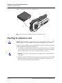
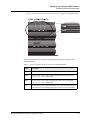
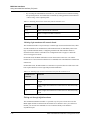
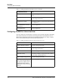
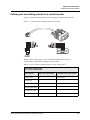
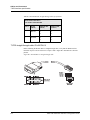
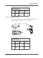
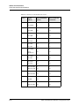
1
MAX™ 6000
Installation and Basic Configuration Guide
Part Number: 7820-0677-001
For software version 8.0.1
March 2000
Copyright© 2000 Lucent Technologies. All rights reserved.
This material is protected by the copyright laws of the United States and other countries. It may not be reproduced, distributed, or altered in any
fashion by any entity (either internal or external to Lucent Technologies), except in accordance with applicable agreements, co ntracts, or licensing,
without the express written consent of Lucent Technologies. For permission to reproduce or distribute, please email your request to
[email protected].
Notice
Every effort was made to ensure that the information in this document was complete and accurate at the time of printing, but information is subject
to change.
Safety, Compliance, and Warranty Information
Before handling any Lucent Access Networks hardware product, read the Access Networks Safety and Compliance Guide included in your product
package. See this guide also to determine how products comply with the electromagnetic interference (EMI) and network compatibility
requirements of your country. See the warranty card included in your product package for the limited warranty that Lucent Technologies provides
for its products.
Security Statement
In rare instances, unauthorized individuals make connections to the telecommunications network through the use of access features.
Trademarks
4ESS, 5ESS, A Network of Expertise, AnyMedia, AqueView, AUDIX, B-STDX 8000, B-STDX 9000, ...Beyond Compare, CaseView, Cajun,
CajunDocs, CAJUNVIEW, Callmaster, CallVisor, CBX 500, CellPipe, ChoiceNet, ClearReach, ComOS, cvMAX, DACScan, Dacsmate, Datakit,
DEFINITY, Definity One, DSL MAX, DSL Terminator, DSLPipe, DSLTNT, Elemedia, Elemedia Enhanced, EMMI, End to End Solutions, EPAC,
ESS, EVEREST, Gigabit-scaled campus networking, Globalview, GRF, GX 250, GX 550, HyperPATH, Inferno, InfernoSpaces, Intragy,
IntragyAccess, IntragyCentral, Intuity, IP Navigator, IPWorX, LineReach, LinkReach, MAX, MAXENT, MAX TNT, Multiband,
Multiband PLUS, Multiband RPM, MultiDSL, MultiVoice, MultiVPN, Navis, NavisAccess, NavisConnect, NavisCore, NavisRadius,
NavisXtend, NetCare, NetLight, NetPartner, OneVision, Open Systems Innovations, OpenTrunk, P550, PacketStar, PathStar, Pinnacle, Pipeline,
PMVision, PortMaster, SecureConnect, Selectools, Series56, SmoothConnect, Stinger, SYSTIMAX, True Access, WaveLAN, WaveMANAGER,
WaveMODEM, WebXtend, and Where Network Solutions Never End are trademarks of Lucent Technologies. Advantage Pak,
Advantage Services, AnyMedia, ...Beyond Compare, End to End Solutions, Inter.NetWorking, MAXENT, and NetWork Knowledge Solutions are
service marks of Lucent Technologies. Other trademarks, service marks, and trade names mentioned in this publication belong to their respective
owners.
Copyrights for Third-Party Software Included in Lucent Access Networks Software Products
C++ Standard Template Library software copyright© 1994 Hewlett-Packard Company and copyright© 1997 Silicon Graphics. Permission to use,
copy, modify, distribute, and sell this software and its documentation for any purpose is hereby granted without fee, provided that the above
copyright notice appear in all copies and that both that copyright notice and this permission notice appear in supporting documentation. Neither
Hewlett-Packard nor Silicon Graphics makes any representations about the suitability of this software for any purpose. It is provided “as is”
without express or implied warranty.
Berkeley Software Distribution (BSD) UNIX software copyright© 1982, 1986, 1988, 1993 The Regents of California. All rights reserved. Redistribution
and use in source and binary forms, with or without modification, are permitted provided that the following conditions are met: 1. Redistributions of source
code must retain the above copyright notice, this list of conditions, and the following disclaimer. 2. Redistributions in binary form must reproduce the above
copyright notice, this list of conditions, and the following disclaimer in the documentation and/or other materials provided with the distribution. 3. All
advertising materials mentioning features or use of this software must display the following acknowledgement: This product includes software developed by
the University of California, Berkeley, and its contributors. 4. Neither the name of the University nor the names of its contributors may be used to endorse or
promote products derived from this software without specific prior written permission.
THIS SOFTWARE IS PROVIDED BY THE REGENTS AND CONTRIBUTORS “AS IS” AND ANY EXPRESS OR IMPLIED WARRANTIES, INCLUDING, BUT
NOT LIMITED TO, THE IMPLIED WARRANTIES OF MERCHANTABILITY AND FITNESS FOR A PARTICULAR PURPOSE ARE DISCLAIMED. IN NO
EVENT SHALL THE REGENTS OR CONTRIBUTORS BE LIABLE FOR ANY DIRECT, INDIRECT, INCIDENTAL, SPECIAL, EXEMPLARY, OR
CONSEQUENTIAL DAMAGES (INCLUDING, BUT NOT LIMITED TO, PROCUREMENT OF SUBSTITUTE GOODS OR SERVICES; LOSS OF USE, DATA
OR PROFITS; OR BUSINESS INTERRUPTION) HOWEVER CAUSED AND ON ANY THEORY OF LIABILITY, WHETHER IN CONTRACT, STRICT
LIABILITY, OR TORT (INCLUDING NEGLIGENCE OR OTHERWISE) ARISING IN ANY WAY OUT OF THE USE OF THIS SOFTWARE, EVEN IF ADVISED
OF THE POSSIBILITY OF SUCH DAMAGE.
Ordering Information
You can order the most up-to-date product information and computer-based training online at http://www.lucent.com/ins/bookstore.
Feedback
Lucent Technologies appreciates your comments, either positive or negative, about this manual. Please send them to [email protected].
Customer Service
Customer Service provides a variety of options for obtaining information about Lucent products and services, software
upgrades, and technical assistance.
Finding information and software on the Internet
Visit the Web site at http://www.lucent.com/ins for technical information, product information, and descriptions of
available services.
Visit the FTP site at ftp://ftp.ascend.com for software upgrades, release notes, and addenda.
Obtaining technical assistance
You can obtain technical assistance by telephone, email, fax, modem, or regular mail, as well as over the Internet.
Gathering information you will need
If you need to contact Lucent for help with a problem, make sure that you have the following information when you call or that
you include it in your correspondence:
•
Product name and model
•
Software and hardware options
•
Software version
•
If supplied by your carrier, Service Profile Identifiers (SPIDs) associated with your line
•
Your local telephone company’s switch type and operating mode, such as AT&T 5ESS Custom or Northern Telecom
National ISDN-1
•
Whether you are routing or bridging with your Lucent product
•
Type of computer you are using
•
Description of the problem
Calling Lucent from within the United States
In the U.S., you can take advantage of Priority Technical Assistance or an Advantage service contract, or you can call to
request assistance.
Priority Technical Assistance
If you need to talk to an engineer right away, call (900) 555-2763 to reach the Priority Call queue. The charge of $2.95 per
minute does not begin to accrue until you are connected to an engineer. Average wait times are less than 3 minutes.
Advantage Services
Advantage Services is a comprehensive selection of services. Installation services help get your Lucent Wide Area Network
(WAN) off to the right start. Ongoing maintenance and support services provide hardware and software solutions to keep your
network operating at peak performance. For more information, call (800) 272-3634.
Lucent Technologies
Other telephone numbers
For a menu of Lucent’s services, call (800) 272-3634. Or call (510) 769-6001 for an operator.
Calling Lucent from outside the United States
You can contact Lucent by telephone from outside the United States at one of the following numbers:
Telephone outside the United States
(510) 769-8027
Austria/Germany/Switzerland
(+33) 492 96 5672
Benelux
(+33) 492 96 5674
France
(+33) 492 96 5673
Italy
(+33) 492 96 5676
Japan
(+81) 3 5325 7397
Middle East/Africa
(+33) 492 96 5679
Scandinavia
(+33) 492 96 5677
Spain/Portugal
(+33) 492 96 5675
UK
(+33) 492 96 5671
For the Asia-Pacific region, you can find additional support resources at
http://www.lucent.com/ins/international/apac/.
Obtaining assistance through correspondence
Send your technical support questions to one of the following email addresses, or correspond by fax, BBS, or regular
mail with Customer Service in Lucent’s U.S. offices in Alameda, CA:
•
Email from within the U.S.—[email protected]
•
Email from Europe, the Middle East, or Africa—[email protected]
•
Email from the Asia-Pacific region—[email protected]
•
Fax—(510) 814-2312
•
Customer Support BBS (by modem)—(510) 814-2302
•
Write to Lucent at the following address:
Attn: Customer Service
Lucent Technologies
1701 Harbor Bay Parkway
Alameda, CA 94502-3002
USA
Contents
About This Guide .............................................................................. xv
What is in this guide ......................................................................................................... ........xv
What you should know .......................................................................................................... .xvi
Documentation conventions ....................................................................................................xvi
Documentation set ................................................................................................................. xvii
Chapter 1
Getting Acquainted with the MAX ................................................. 1-1
What is a MAX? .................................................................................................................... 1-1
Checking the MAX base unit ................................................................................................. 1-2
Interfaces on the MAX base unit .................................................................................... 1-3
Power ....................................................................................................................... 1-3
Control ..................................................................................................................... 1-3
LAN UTP ................................................................................................................ 1-3
PCMCIA .................................................................................................................. 1-4
DRAM ..................................................................................................................... 1-4
SERIAL V.35 DTE port .......................................................................................... 1-4
WAN (1 to 4) ........................................................................................................... 1-4
ALARM ................................................................................................................... 1-4
Locating expansion cards ....................................................................................................... 1-4
Host/6 card ............................................................................................................... 1-4
ISDN BRI network-interface and terminal-interface cards ..................................... 1-5
Multiband inverse-multiplexing card ...................................................................... 1-5
K56 modem card ..................................................................................................... 1-5
V.90 S56 III modem card (Series56 III) .................................................................. 1-5
V.110 card ............................................................................................................... 1-5
PIAFS-16 card ......................................................................................................... 1-6
IDSL card ................................................................................................................ 1-6
DRAM card ............................................................................................................. 1-6
PCMCIA flash card ................................................................................................. 1-7
PALMTOP interface ................................................................................................ 1-7
Locating MAX cables ............................................................................................................ 1-8
Locating other MAX package contents ................................................................................. 1-8
Chapter 2
Setting Up and Testing the MAX Hardware .................................. 2-1
Planning the hardware installation ......................................................................................... 2-1
What you need before you start ...................................................................................... 2-1
Digital modem card support ........................................................................................... 2-2
Installing the MAX without a rack ........................................................................................ 2-2
Installing the MAX in a rack .................................................................................................. 2-2
Connecting the MAX to a terminal ................................................................................. 2-2
Power switches and cables ..................................................................................................... 2-3
MAX 6000 Installation and Basic Configuration Guide
v
Contents
Inserting an expansion card .................................................................................................... 2-4
Connecting to a LAN ............................................................................................................. 2-6
Connecting the MAX to a T1 line .......................................................................................... 2-6
Connecting the MAX to an E1 line ........................................................................................ 2-6
Interpreting the MAX indicator lights ................................................................................... 2-8
MAX front panel ............................................................................................................. 2-8
MAX back panel ........................................................................................................... 2-10
Starting the MAX ................................................................................................................. 2-10
Chapter 3
MAX User Interfaces ....................................................................... 3-1
Accessing the VT100 interface .............................................................................................. 3-1
Preparing a terminal, PC, or workstation for use as a MAX console ............................. 3-2
Using a console connection to access the VT100 interface ............................................ 3-2
Using Telnet to access the VT100 interface ................................................................... 3-2
Using configuration menus .................................................................................................... 3 -3
Main Edit Menu .............................................................................................................. 3-3
Understanding menu numbers ................................................................................. 3-3
System—virtual slot 00-00 ...................................................................................... 3-4
T1 or E1—slots 10-000 and 20-000 ........................................................................ 3-4
Expansion slots—slots 30-000 through 80-000 ....................................................... 3-4
Ethernet slot—slot 90-000 ....................................................................................... 3-5
Ether Data slots—virtual slots A0-000, C0-000, and D0-000 ................................. 3-5
Serial WAN slot—slot B0-000 ................................................................................ 3-5
Profiles ............................................................................................................................ 3-5
Navigating the VT100 interface ..................................................................................... 3-6
Activating menus or status windows .............................................................................. 3-6
Opening menus and profiles ........................................................................................... 3-6
Setting parameters ........................................................................................................... 3-8
Setting enumerated parameters ................................................................................ 3-8
Opening edit fields ................................................................................................... 3-8
Saving your changes ....................................................................................................... 3-9
Creating and saving a profile .......................................................................................... 3-9
Activating a profile ....................................................................................................... 3-10
Using the DO menu ...................................................................................................... 3-11
Managing MAX configuration and management sessions .................................... 3-11
Testing and troubleshooting .................................................................................. 3-12
Managing calls ....................................................................................................... 3-12
Using command-line-interface (CLI) tools .......................................................................... 3-13
Using the terminal-server CLI ...................................................................................... 3-13
Preparing for terminal-server sessions .................................................................. 3-13
Starting terminal-server sessions ........................................................................... 3-13
Ending terminal-server sessions ............................................................................ 3-14
Terminal-server functions ...................................................................................... 3-14
Using the Diagnostic-mode CLI ................................................................................... 3-18
Accessing and quitting the Diagnostic-mode CLI ................................................. 3-18
Using diagnostic commands .................................................................................. 3-18
Listing Diagnostic-mode commands ..................................................................... 3-19
Getting information about modem activity ........................................................... 3-19
Managing memory content .................................................................................... 3-20
Adding optional features to the MAX ................................................................... 3-21
Viewing the fatal-error history log ........................................................................ 3-21
Using status windows ........................................................................................................... 3-21
vi
MAX 6000 Installation and Basic Configuration Guide
Contents
Activating and navigating status windows ................................................................... 3-22
Default status window displays .................................................................................... 3-22
Line status window ................................................................................................ 3-23
Modem Stat window .............................................................................................. 3-23
Session and system status windows ....................................................................... 3-25
WAN and Ethernet status windows ....................................................................... 3-26
Sys Option and Main Status Menu windows ......................................................... 3-27
Specifying which status windows appear ..................................................................... 3-28
Specialized interfaces for MAX configuration and network management .......................... 3-28
Simple Network Management Protocol (SNMP) ......................................................... 3-28
Syslog host reporting .................................................................................................... 3-29
Navis network management applications ..................................................................... 3-29
RADIUS-based products .............................................................................................. 3-29
Chapter 4
Preparing to Configure the MAX ................................................... 4-1
Preparing the MAX and network ........................................................................................... 4-1
Assigning an IP address to the MAX ..................................................................................... 4-2
Securing the MAX from unauthorized configuration changes .............................................. 4-3
Restricting the default access .......................................................................................... 4-3
Changing the password in the Full Access Security profile ........................................... 4-6
Setting password protection for Telnet access ................................................................ 4-7
Setting password protection for SNMP access ............................................................. 4-10
Setting MAX system options ............................................................................................... 4-12
Activating administrative permissions .......................................................................... 4-12
Establishing a system name and other system characteristics ...................................... 4-12
Establishing Syslog logging .......................................................................................... 4-13
Configuring UNIX host’s Syslog daemon .................................................................... 4-13
Chapter 5
Basic Configuration Tasks............................................................. 5-1
Establishing TCP/IP connectivity through the Ether Options profile .................................... 5-1
Establishing WAN connectivity through Connection profiles .............................................. 5-1
Connection profile functions .......................................................................................... 5-2
Identifying the remote device or caller .................................................................... 5-2
Defining encapsulation ............................................................................................ 5-2
Defining a routing protocol ..................................................................................... 5-3
Defining the call session .......................................................................................... 5-4
Defining telco call preferences ................................................................................ 5-5
Specifying accounting requirements ....................................................................... 5-5
Specifying Dynamic Host Configuration Protocol (DHCP) settings ...................... 5-5
Handling incoming calls through the Answer profile ............................................................ 5-6
Determining which calls are answered ........................................................................... 5-6
Building a connection through the Answer profile ......................................................... 5-6
Defining encapsulation ............................................................................................ 5-6
Defining the call session .......................................................................................... 5-7
Specifying DHCP settings ....................................................................................... 5-8
Establishing dial-in calls through terminal-server connections ............................................. 5-8
How the terminal server handles calls ............................................................................ 5-8
PPP-encapsulated calls ............................................................................................ 5-8
Non-PPP calls .......................................................................................................... 5-8
Terminal-server configuration tasks ............................................................................... 5-9
Setting up digital modems for call handling ............................................................ 5-9
MAX 6000 Installation and Basic Configuration Guide
vii
Contents
Enabling the terminal server and setting up login procedures ................................. 5-9
Enabling dial-in users to connect to hosts through the terminal-server
command line (terminal mode) ............................................................... 5-10
Using Rlogin and Telnet from the command line ................................................. 5-10
Starting PPP sessions from the command line ...................................................... 5-11
Connecting dial-in users directly to hosts (immediate mode) ............................... 5-11
Providing dial-in users with a menu of hosts (menu mode) .................................. 5-11
Establishing dial-out calls through terminal-server connections ......................................... 5-12
Using immediate modem dial out ................................................................................. 5-12
Using nonimmediate modem dial out ........................................................................... 5-12
Chapter 6
Quickstart ........................................................................................ 6-1
Making required preparations ................................................................................................ 6-1
Configuring the Ethernet interface ......................................................................................... 6-2
Gathering configuration information for your Ethernet interface .................................. 6-2
Setting the parameters for the Ethernet interface ............................................................ 6-4
Specifying the IP address and subnet mask ............................................................. 6-4
Specifying RIP management (optional) .................................................................. 6-4
Configuring DNS (optional) .................................................................................... 6-5
Setting up the default route (optional) ..................................................................... 6-5
Testing the LAN connection .................................................................................................. 6-6
Configuring WAN lines ......................................................................................................... 6-7
BRI line configuration .................................................................................................... 6-7
Gathering configuration information for your BRI lines ......................................... 6-7
Configuring BRI lines ............................................................................................. 6-9
T1/PRI line configuration ............................................................................................. 6-10
ISDN signaling ...................................................................................................... 6-10
Inband signaling .................................................................................................... 6-10
Gathering configuration information for your T1 interface .................................. 6-11
Configuring the T1/PRI lines ........................................................................................ 6-14
Checking the line’s status ...................................................................................... 6-16
E1/PRI line configuration ............................................................................................. 6-17
ISDN signaling ...................................................................................................... 6-17
R2 signaling ........................................................................................................... 6-18
Gathering configuration information for your E1 interface .................................. 6-19
Configuring the E1/PRI lines ................................................................................ 6-21
Checking the line’s status ...................................................................................... 6-23
Testing the WAN connection ............................................................................................... 6-24
Chapter 7
Next Steps ....................................................................................... 7-1
Configuring MAX functionality ............................................................................................ 7-1
Lines, slots, and ports ..................................................................................................... 7-1
WAN connections ........................................................................................................... 7-2
Security ........................................................................................................................... 7-3
Configuring the MAX for Internet services .................................................................... 7-4
Configuring the MAX as an IPX router .......................................................................... 7-5
Configuring the MAX for Frame Relay ......................................................................... 7-5
Configuring the MAX as a link-level bridge .................................................................. 7-6
Managing MAX units ............................................................................................................ 7-6
viii
MAX 6000 Installation and Basic Configuration Guide
Contents
Appendix A
Provisioning the Switch .................................................................A-1
Provisioning the switch for T1 access ................................................................................... A-1
Provisioning the switch for T1/PRI access ........................................................................... A-2
Provisioning the switch for E1/PRI access ........................................................................... A-3
What you need from your E1/PRI service provider ...................................................... A-3
Supporting E1/PRI WAN switched services ................................................................. A-3
Provisioning the switch for ISDN BRI access ...................................................................... A-3
Parameters on the MAX ................................................................................................ A-4
Information required from the ISDN BRI provider ....................................................... A-5
Generic SPIDs for NI-1 and NI-2 Service .............................................................. A-5
SPIDs for a 5ESS Switch ........................................................................................ A-6
SPIDs for a Northern Telecom DMS-100 Switch .................................................. A-6
Appendix B
Cables and Connectors ..................................................................B-1
User interface specifications ..................................................................................................B-1
Control-port and cabling pinouts for the control monitor and MIF ................................B-1
Pinouts for the palmtop controller ..................................................................................B-2
Palmtop-port and cabling pinouts for a control monitor .................................................B-3
Ethernet interface specifications ............................................................................................B-4
10BaseT cables ...............................................................................................................B-4
100BaseT cables .............................................................................................................B-4
T1/PRI interface specifications ..............................................................................................B-4
T1/PRI CSU requirements ..............................................................................................B-4
Port with internal CSU ............................................................................................B-4
Port without internal CSU .......................................................................................B-5
T1/PRI cable specifications ............................................................................................B-6
T1/PRI crossover cable: RJ-48C/RJ-48C ................................................................B-6
T1/PRI straight-through cable: RJ-48C/RJ-48C ......................................................B-7
T1/PRI straight-through cable: RJ-48C/DA-15 .......................................................B-8
T1/PRI crossover cable: RJ-48C/DA ......................................................................B-9
T1/PRI straight-through cable: RJ-48C/Bantam ...................................................B-10
T1 RJ-48C-Loopback plug ....................................................................................B-11
T1/PRI WAN ports .......................................................................................................B-11
WAN switched services available to the MAX ............................................................B-11
E1/PRI interface specifications ............................................................................................B-12
E1/PRI cable specifications ..........................................................................................B-12
E1/PRI crossover cable: RJ-48C/RJ-48C ..............................................................B-12
E1/PRI straight-through cable: RJ-48C/RJ-48C ....................................................B-13
E1/PRI straight-through cable: RJ-48C/DA-15 .....................................................B-14
E1/PRI crossover cable: RJ-48C/DA ....................................................................B-15
E1/PRI straight-through cable: RJ-48C/Bantam ...................................................B-16
E1/PRI WAN ports .......................................................................................................B-17
ISDN BRI interface specifications .......................................................................................B-17
Net/BRI module interfaces ...........................................................................................B-17
Host/BRI module (expansion card) interface ...............................................................B-18
Serial host interface specifications .......................................................................................B-18
V.35 cabling ..................................................................................................................B-20
V.35/V.25 bis cable to Cisco .................................................................................B-20
V.35 cable to generic serial host ............................................................................B-22
V.35/RS-366 cable to generic serial host ..............................................................B-23
V.35/RS-366 cable to CLI .....................................................................................B-25
MAX 6000 Installation and Basic Configuration Guide
ix
Contents
V.35/RS-366 cable to PictureTel ...........................................................................B-27
RS-366 cabling .............................................................................................................B-29
RS-449/RS-366/DB-37 cable to Video Telecom ..................................................B-29
RS-449/RS-366 cable to generic serial host ..........................................................B-31
RS-449 cable to generic serial host .......................................................................B-33
X.21 cabling ..................................................................................................................B-35
Cable length requirements ............................................................................................B-36
Serial WAN cabling specifications ......................................................................................B-37
V.35 cable to WAN ......................................................................................................B-37
RS-449 cable to WAN ..................................................................................................B-38
IDSL specifications ..............................................................................................................B-39
General specifications ...................................................................................................B-39
Network-interface specifications ..................................................................................B-39
Loopback testing ...........................................................................................................B-40
Appendix C
Safety-Related Electrical, Physical, and Environmental Information
C-1
Electrical specifications .........................................................................................................C-1
Battery specifications .............................................................................................................C-2
Physical specifications ...........................................................................................................C-3
Alarm relay operating specifications .....................................................................................C-3
Environmental requirements ..................................................................................................C-3
Index........................................................................................... Index-1
x
MAX 6000 Installation and Basic Configuration Guide
Figures
Figure 1-1 MAX base unit (ac)............................................................................................ 1-2
Figure 1-2 Redundant MAX base unit (ac) ......................................................................... 1-2
Figure 1-3 MAX 6000 base unit (dc) with power source.................................................... 1-3
Figure 1-4 Host/6 card ......................................................................................................... 1-4
Figure 1-5 ISDN BRI network-interface or terminal-interface card ................................... 1-5
Figure 1-6 Multiband inverse-multiplexing two-port card.................................................. 1-5
Figure 1-7 V.90 S56III digital modem card ........................................................................ 1-5
Figure 1-8 V.110 card.......................................................................................................... 1-5
Figure 1-9 PIAFS card......................................................................................................... 1-6
Figure 1-10 IDSL card........................................................................................................... 1-6
Figure 1-11 DRAM card........................................................................................................ 1-7
Figure 1-12 PCMCIA card .................................................................................................... 1-7
Figure 2-1 MAX base unit’s switch and cord adapter (ac).................................................. 2-3
Figure 2-2 Redundant MAX base unit’s switch and cord adapter (ac) ............................... 2-3
Figure 2-3 MAX base unit’s power cord adapter (dc)......................................................... 2-4
Figure 2-4 Inserting an expansion card into a MAX slot .................................................... 2-5
Figure 2-5 Tightening slot card thumbscrews ..................................................................... 2-5
Figure 2-6 MAX 6000 E1 or T1 unit’s LAN/UTP port ...................................................... 2-6
Figure 2-7 Location of the LAN/UTP and E1 ports on a MAX 6000 E1 model ................ 2-7
Figure 2-8 Location of the MAX indicator lights................................................................ 2-8
Figure 2-9 Location of the indicator lights for the power supply on the Redundant MAX 2-9
Figure 2-10 Ethernet interface indicator lights on MAX back panel .................................. 2-10
Figure 3-1 Slot and port numbering in the MAX 6000 ....................................................... 3-4
Figure 4-1 ISDN setup with MAX placing and receiving calls on LAN and WAN ....... 4-2
Figure 6-1 ISDN setup .................................................................................................... 6-2
Figure 6-2 Incoming call routing using ISDN T1/PRI signaling ...................................... 6-10
Figure 6-3 Incoming call routing using inband signaling and hunt groups....................... 6-11
Figure 6-4 Incoming call routing using ISDN E1/PRI signaling ...................................... 6-18
Figure 6-5 Incoming call routing using R2 signaling........................................................ 6-18
Figure 7-1 Control-monitor and MIF palmtop port and cable............................................. B-3
Figure B-1 RJ-48C/RJ-48C crossover cable ........................................................................ B-6
Figure B-2 RJ-48C/RJ-48C straight-through cable specifications....................................... B-7
Figure B-3 RJ-48C/DA-15 straight-through cable............................................................... B-8
Figure B-4 RJ-48C/DA crossover cable............................................................................... B-9
Figure B-5 RJ-48C/Bantam straight-through cable ........................................................... B-10
Figure B-6 RJ-48C/RJ-48C crossover cable ...................................................................... B-12
Figure B-7 RJ-48C/RJ-48C straight-through cable specifications..................................... B-13
Figure B-8 RJ-48C/DA-15 straight-through cable............................................................. B-14
Figure B-9 RJ-48C/DA crossover cable............................................................................. B-15
Figure B-10 RJ-48C/Bantam straight-through cable ........................................................... B-16
Figure B-11 V.35/V.25 bis cable to Cisco ........................................................................... B-20
Figure B-12 V.35 cable to generic serial host ...................................................................... B-22
Figure B-13 V.35/RS-366 cable to generic serial host......................................................... B-23
MAX 6000 Installation and Basic Configuration Guide
xi
Figures
Figure B-14 V.35/RS-366 cable to CLI codec ..................................................................... B-25
Figure B-15 V.35/RS-366 cable to PictureTel ..................................................................... B-27
Figure B-16 RS-449/RS-366/DB-37 cable to Video Telecom codec .................................. B-29
Figure B-17 RS-449/RS-366 cable to generic serial host .................................................... B-31
Figure B-18 RS-449 cable to generic serial host.................................................................. B-33
Figure B-19 X.21 cable to generic serial host ...................................................................... B-35
xii
MAX 6000 Installation and Basic Configuration Guide
Tables
Table 2-1
Table 2-2
Table 2-3
Table 3-1
Table 3-2
Table 3-3
Table 3-4
Table 3-5
Table 3-6
Table 3-7
Table 3-8
Table 3-9
Table 3-10
Table 3-11
Table 3-12
Table 3-13
Table 3-14
Table 3-15
Table 3-16
Table 3-17
Table 3-18
Table 5-1
Table 5-2
Table 6-1
Table 6-2
Table 6-3
Table 6-4
Table 7-1
Table 7-2
Table 7-3
Table 7-4
Table 7-5
Table 7-6
Table 7-7
Table 7-8
Table A-1
Table A-2
Table A-3
Table B-1
Table B-2
Table B-3
Table B-4
Table B-5
MAX front panel indicator lights....................................................................... 2-8
indicator lights for the power supply on the Redundant MAX......................... 2-9
Ethernet-interface indicator lights on back panel ............................................ 2-10
Summary of purpose of Ether Options, Answer, and Connection profiles ....... 3-5
Navigating the MAX user interface................................................................... 3-6
DO menu commands for session management................................................ 3-11
DO menu commands for testing and troubleshooting ..................................... 3-12
DO menu commands for call management...................................................... 3-12
Commands for ending terminal-server sessions .............................................. 3-14
Managing MAX units from the terminal server .............................................. 3-14
Monitoring and managing IP and IPX routing from the terminal server......... 3-15
Initiating host-to-host connections from the terminal server........................... 3-16
Initiating login sessions with remote hosts from the terminal server .............. 3-16
Dialing out through digital modems from the terminal server ........................ 3-17
X.25 management from the terminal server .................................................... 3-17
Tunnel management from the terminal server ................................................. 3-17
Getting information about diagnostic commands ............................................ 3-19
Obtaining diagnostic information about modem activity ................................ 3-19
Commands for managing the MAX unit’s memory ........................................ 3-20
Commands for fatal-error history log usage .................................................... 3-21
Modem-status characters ................................................................................. 3-25
Subprofiles in Ethernet > Connections > any Connection profile ..................... 5-3
Terminal-server commands for digital modems .............................................. 5-13
Ethernet configuration information.................................................................... 6-2
BRI line configuration information ................................................................... 6-7
T1 line configuration information.................................................................... 6-11
E1 line configuration information.................................................................... 6-19
Finding information about lines, slots, and ports............................................... 7-1
Finding information about WAN connections................................................... 7-2
Finding information about WAN security ......................................................... 7-3
Finding information about IP routing for Internet services ............................... 7-4
Finding information about IPX routing ............................................................. 7-5
Finding information about using the MAX as a Frame Relay concentrator...... 7-5
Finding information about using the MAX as link-level bridge ....................... 7-6
Finding information about MAX management ................................................. 7-6
T1 access provisioning information.................................................................. A-1
AT&T 5ESS provisioning information............................................................. A-4
Northern Telecom provisioning information .................................................... A-5
Control-monitor and MIF control-port and cabling pinouts .............................. B-1
Palmtop-controller pinouts ................................................................................ B-2
Control-monitor and MIF palmtop-port and cabling pinouts ............................ B-3
CSU specifications............................................................................................. B-5
RJ-48C/RJ-48C crossover cable specifications ................................................. B-7
MAX 6000 Installation and Basic Configuration Guide
xiii
Tables
Table B-6
Table B-7
Table B-8
Table B-9
Table B-10
Table B-11
Table B-12
Table B-13
Table B-14
Table B-15
Table B-16
Table B-17
Table B-18
Table B-19
Table B-20
Table B-21
Table B-22
Table B-23
Table B-24
Table B-25
Table B-26
Table B-27
Table B-28
Table B-29
Table B-30
Table C-1
Table C-2
Table C-3
xiv
RJ-48C/RJ-48C straight-through cable specifications....................................... B-8
RJ-48C/DA-15 straight-through cable specifications........................................ B-9
RJ-48C/DA crossover cable specifications...................................................... B-10
RJ-48C/Bantam straight-through cable specifications..................................... B-10
RJ-48C-Loopback plug specifications............................................................. B-11
Transmit and Receive pins............................................................................... B-11
RJ-48C/RJ-48C crossover cable specifications ............................................... B-13
RJ-48C/RJ-48C straight-through cable specifications..................................... B-14
RJ-48C/DA-15 straight-through cable specifications...................................... B-14
RJ-48C/DA crossover cable specifications...................................................... B-15
RJ-48C/Bantam straight-through cable specifications..................................... B-16
Transmit and Receive pins............................................................................... B-17
Serial host interface cabling abbreviations ...................................................... B-18
Pinouts for V.35/V.25 bis cable to Cisco......................................................... B-20
Pinouts for V.35 cable to generic serial host ................................................... B-22
Pinouts for V.35/RS-366 cable to generic serial host ...................................... B-24
Pinouts for V.35/RS-366 cable to CLI............................................................. B-26
Pinouts for V.35/RS-366 cable to PictureTel .................................................. B-28
Pinouts for RS-449/RS-366/DB-37 cable to VTC........................................... B-30
Pinouts for RS-449/RS-366 cable to generic serial host.................................. B-32
Pinouts for RS-449 cable to generic serial host ............................................... B-34
Pinouts for X.21 cable to generic serial host ................................................... B-35
Cable length requirements ............................................................................... B-36
V.35 cable pinouts ........................................................................................... B-37
RS-449 cable pinouts ....................................................................................... B-38
Electrical specifications for MAX 6000 ac version........................................... C-1
Electrical specifications for MAX 6000 dc version........................................... C-2
MAX 6000 battery specifications ...................................................................... C-2
MAX 6000 Installation and Basic Configuration Guide
About This Guide
This guide explains how to install and test the MAX™ 6000 series hardware (referred to
hereafter as the MAX). It also explains how to navigate the user interface and set basic
Ethernet and line configuration parameters. When you finish with the instructions in this guide,
you will be ready to configure the MAX.
!
Warning: Before installing the MAX, be sure to read the safety instructions in the Access
Networks Safety and Compliance Guide. This hardware installation guide provides
information specific to your product in Appendix C, “Safety-Related Electrical, Physical, and
Environmental Information.”
What is in this guide
Following is a chapter-by-chapter description of the topics in this guide:
•
Chapter 1, “Getting Acquainted with the MAX,” describes the main features of the MAX
and lists package contents.
•
Chapter 2, “Setting Up and Testing the MAX Hardware,” explains how to install the MAX
on the network, insert expansion cards, and test the hardware.
•
Chapter 3, “MAX User Interfaces,” tells how to access the MAX menu interface and
associated command-line interfaces and use them for configuring and monitoring the
MAX. It also introduces specialized interfaces available from Lucent Technologies or
other sources.
•
Chapter 4, “Preparing to Configure the MAX,” tells how to prepare for configuration by
assigning an IP address, setting security parameters and passwords to protect the
configuration interface from unauthorized use, and setting basic system-related options
such as name, location, time, and Syslog server.
•
Chapter 5, “Basic Configuration Tasks,” describes how you use the True Access™
Operating System (TAOS) Ether Options profile, Answer profile, and Connection profiles
to prepare the MAX to receive and send calls over Local Area Networks (LANs) and
Wide Area Networks (WANs).
•
Chapter 6, “Quickstart,” explains how to configure and test your MAX unit’s Ethernet and
ISDN line interfaces.
•
Chapter 7, “Next Steps,” summarizes additional configuration tasks you might need to
perform and provides references to other MAX documentation with related information.
•
Appendix A, “Provisioning the Switch,” gives you information that your T1/ISDN
Primary Rate Interface (PRI), E1, or ISDN Basic Rate Interface (BRI) service provider
needs to properly provision the Central Office switch.
•
Appendix B, “Cables and Connectors,” provides specifications for different facets of the
MAX, and includes cabling requirements.
MAX 6000 Installation and Basic Configuration Guide
xv
About This Guide
What you should know
•
Appendix C, “Safety-Related Electrical, Physical, and Environmental Information” shows
regulatory notices and warnings.
•
An index.
Note: This guide describes the full set of features for MAX 6000 units running the 8.0.1
version of TAOS. Some features might not be available with earlier versions or specialty loads
of the software.
What you should know
This guide is for the person who configures and maintains MAX units. To configure a unit, you
need to understand the following:
•
Internet or telecommuting concepts
•
WAN concepts
•
LAN concepts, if applicable
Documentation conventions
Following are all the special characters and typographical conventions used in this guide:
Convention
Meaning
Monospace text Represents text that appears on your computer’s screen, or that could
appear on your computer’s screen.
Boldface mono- Represents characters that you enter exactly as shown (unless the charspace text
acters are also in italics—see Italics, below). If you could enter
the characters but are not specifically instructed to, they do not appear
in boldface.
xvi
Italics
Represent variable information. Do not enter the words themselves in
the command. Enter the information they represent. In ordinary text,
italics are used for titles of publications, for some terms that would
otherwise be in quotation marks, and to show emphasis.
[]
Square brackets indicate an optional argument you might add to a
command. To include such an argument, type only the information
inside the brackets. Do not type the brackets unless they appear in bold
type.
|
Separates command choices that are mutually exclusive.
>
Points to the next level in the path to a parameter or menu item. The
item that follows the angle bracket is one of the options that appears
when you select the item that precedes the angle bracket.
Key1-Key2
Represents a combination keystroke. To enter a combination keystroke, press the first key and hold it down while you press one or
more other keys. Release all the keys at the same time. (For example,
Ctrl-H means hold down the Control key and press the H key.)
Press Enter
Means press the Enter, or Return, key or its equivalent on your computer.
MAX 6000 Installation and Basic Configuration Guide
About This Guide
Documentation set
Convention
Meaning
Note:
Introduces important additional information.
!
Caution:
!
Warning:
Warns that a failure to follow the recommended procedure could result
in loss of data or damage to equipment.
Warns that a failure to take appropriate safety precautions could result
in physical injury.
Warns of danger of electric shock.
Warning:
Note: In a menu-item path, include a space before and after each “>” character.
Documentation set
The MAX 6000 documentation set consists of the following manuals:
•
MAX Administration Guide
•
MAX 6000 Installation and Basic Configuration Guide (this volume)
•
MAX 3000/6000 Network Configuration Guide
•
MAX Reference
•
MAX Security Supplement
•
TAOS RADIUS Guide and Reference
•
TAOS Glossary
•
Remote Access Networking Services Technology Overview
The MAX documentation set is available on the Documentation Library CD-ROM included
with your MAX, and on either CD-ROM or paper from the online bookstore
(http://www.lucent.com/ins/bookstore).
MAX 6000 Installation and Basic Configuration Guide
xvii
Getting Acquainted with the MAX
1
What is a MAX? . . . . . . . . . . . . . . . . . . . . . . . . . . . . . . . . . . . . . . . . . . . . . . . . . . . . . . 1-1
Checking the MAX base unit. . . . . . . . . . . . . . . . . . . . . . . . . . . . . . . . . . . . . . . . . . . . . 1-2
Locating expansion cards. . . . . . . . . . . . . . . . . . . . . . . . . . . . . . . . . . . . . . . . . . . . . . . . 1-4
Locating MAX cables . . . . . . . . . . . . . . . . . . . . . . . . . . . . . . . . . . . . . . . . . . . . . . . . . . 1-8
Locating other MAX package contents . . . . . . . . . . . . . . . . . . . . . . . . . . . . . . . . . . . . . 1-8
Familiarize yourself with the MAX and optional expansion cards you ordered. Make sure that
you have everything you need to begin setting up the MAX.
What is a MAX?
The MAX is a WAN access router designed for central site remote access applications. It has
the following main features:
•
Supports digital WAN access for numerous WAN services.
•
Allows digital and analog modems to dial in over channelized BRI, T1/PRI, or E1/PRI
access lines.
•
Provides IP and IPX routing, bridging, and terminal-server functions.
•
Aggregates multiple calls for bandwidth-on-demand.
•
Supports multiple security methods.
•
Provides various management and control features.
MAX 6000 Installation and Basic Configuration Guide
1-1
Getting Acquainted with the MAX
Checking the MAX base unit
Checking the MAX base unit
Open the shipping package and make sure you have received the base MAX that you ordered.
Figure 1-1 shows the ac MAX base unit. Figure 1-2 shows the ac Redundant MAX base unit.
Figure 1-3 shows the dc MAX base unit with its dc power source, which is also present on the
dc Redundant MAX 6000 unit (not shown). A Redundant MAX 6000 has a second, identical
power source that takes over if the primary power source fails.
Figure 1-1. MAX base unit (ac)
Figure 1-2. Redundant MAX base unit (ac)
1-2
MAX 6000 Installation and Basic Configuration Guide
Getting Acquainted with the MAX
Checking the MAX base unit
Figure 1-3. MAX 6000 base unit (dc) with power source
N
WA
4
M
3
2
AR
AL
1
L
RIA
SE
ACT
FDX
T
100B
COL
LNK
IA
MC
PC
AM
DR
TYPE
D
FUSE 2A
RATE
,
250V
T
AC
-48
RTN
P
N UT
LA
-48
RTN
60V
16A
L
L
RO
NT
CO
CO
K
LN
IA
MC
PC
AM
PE
TY
SE D
FU ATE2A
R V,
0
25
DR
-48
N
RT
TP
NU
LA
-48
N
RT
V
60
A
16
L
RO
NT
CO
Interfaces on the MAX base unit
The MAX 6000 has a number of interfaces on the base unit, and others are available on
expansion cards.
Figure 1-1 on page 1-2 and Figure 1-2 on page 1-2 show the physical interfaces on the MAX
base unit.
Power
The MAX accepts ac or dc power, depending on the model you purchased. Figure 1-1 on page
1-2 and Figure 1-2 on page 1-2 show ac power sockets. Figure 1-3 on page 1-3 shows the dc
power socket. (For further details, see Appendix C, “Safety-Related Electrical, Physical, and
Environmental Information.”)
Control
The control port connects to a VT100 terminal or a modem to provide the menu-driven user
interface to the MAX. The interface runs at 9600 bps, 8 bits per character, no parity, no flow
control, 1 stop bit and direct connect. You can set the bits-per-second rate through the user
interface. (For details about cables that connect to this port, see “User interface specifications”
on page B-1.)
LAN UTP
The LAN UTP port connects the MAX to an unshielded twisted pair UTP 10/100 BaseT LAN.
(For details about cables that connect to this port, see “Ethernet interface specifications” on
page B-4.)
MAX 6000 Installation and Basic Configuration Guide
1-3
Getting Acquainted with the MAX
Locating expansion cards
PCMCIA
The Personal Computer Memory Card International Association (PCMCIA) interface accepts
a plug-in PCMCIA card. (For an illustration, see Figure 1-12 on page 1-7.)
DRAM
The DRAM interface accepts a plug-in dynamic RAM (DRAM) card. (For an illustration, see
Figure 1-11 on page 1-7.)
SERIAL V.35 DTE port
The SERIAL interface is a V.35 data terminal equipment DTE port that provides a
point-to-point connection between the MAX and another device. In the MAX manuals, this
port is called the serial WAN port. (For details about cables that connect to the serial V.35 DTE
port, see “Serial WAN cabling specifications” on page B-37.)
WAN (1 to 4)
The WAN ports are a group of four T1 or four E1 ports providing point-to-point T1/E1
connections between the MAX and other devices. In the MAX manuals, these ports are called
Net/T1 and Net/E1 ports. (For details about cables that connect to the WAN ports, see “T1/PRI
interface specifications” on page B-4 and “E1/PRI interface specifications” on page B-12.
ALARM
The ALARM interface is a two-connector terminal block that provides warning of alarm
conditions. (For further information about the alarm relay, see “Alarm relay operating
specifications” on page C-3.)
Locating expansion cards
The MAX accommodates up to six expansion cards (also referred to as expansion modules or
slot cards). The following figures will help you to identify your expansion cards and their
interfaces.
!
Caution: A MAX unit’s expansion cards are not hot-swappable and should not be removed
while the unit is running.
Host/6 card
The Host/6 card (Figure 1-4), also known as the AIM/6 card, supports six V.35 host ports. A
Host/6 card supports 32 active channels. You can install a maximum of two Host/6 cards in the
MAX.
Figure 1-4. Host/6 card
1-4
MAX 6000 Installation and Basic Configuration Guide
Getting Acquainted with the MAX
Locating expansion cards
ISDN BRI network-interface and terminal-interface cards
The ISDN BRI network-interface card and ISDN terminal-interface card each have eight ISDN
BRI ports (as shown in Figure 1-5). You can install a maximum of two ISDN BRI
network-interface cards in the MAX.
Figure 1-5. ISDN BRI network-interface or terminal-interface card
Multiband inverse-multiplexing card
The Multiband® inverse-multiplexing card (Figure 1-6) has two or six user-selectable RS-449,
V.35, or X.21 serial host ports with inverse-multiplexing and RS-366 capability, V.25bis, or
control-lead signaling.
Figure 1-6. Multiband inverse-multiplexing two-port card
The data circuit-terminating equipment (DCE) interfaces in Figure 1-4 and Figure 1-6 provide
AIM/BONDING inverse-multiplexing services to devices connected to them.
K56 modem card
You can install the K56 modem card in the same MAX that has V.90 S56 III modem cards
already installed. The K56 modem card provides 8, 12, or 16 modems, depending on the
number of modems on the card.
V.90 S56 III modem card (Series56 III)
You can install the V.90 S56 III modem card (Series56™ III) in the same MAX that has K56
modem cards already installed. The V.90 S56 III modem card (Figure 1-7) provides 18, 24 or
30 modems. The card can terminate both modem and High Level Data Link Control (HDLC)
calls.
Figure 1-7. V.90 S56III digital modem card
V.110 card
The V.110 card (Figure 1-8) supports as many as eight V.110 WAN sessions. You can install a
maximum of two V.110 cards in the MAX.
Figure 1-8. V.110 card
MAX 6000 Installation and Basic Configuration Guide
1-5
Getting Acquainted with the MAX
Locating expansion cards
PIAFS-16 card
PIAFS-16 card (Figure 1-9) supports as many as 16 Personal Handyphone System (PHS)
Internet Access Forum Standards (PIAFS) WAN sessions. You can install a maximum of two
PIAFS-16 cards in the MAX.
Figure 1-9. PIAFS card
IDSL card
The Lucent Technologies ISDN Digital Subscriber Line (IDSL) card (Figure 1-10) appears as
BRI/LT in the VT100 menu screen and supports incoming and outgoing voice calls. To
support outgoing voice calls, the connected Terminal Equipment (TE) must use Q.931 en-bloc
dialing to send all dialed digits to the MAX in one block (the ISDN Call Setup message), rather
than sending 1digit at a time.
The MAX receives outgoing call requests from attached ISDN TE devices and routes voice
calls to the Public Switched Telephone Network (PSTN) over a T1 line or ISDN PRI line. The
MAX receives incoming voice calls and uses Dialed Number Identification Service (DNIS) to
route them to TE devices connected to IDSL cards.
Figure 1-10. IDSL card
The IDSL ports (Figure 1-10) are a group of eight DCE ports providing point-to-point IDSL
connections between the MAX and other devices. An IDSL port has the same pinouts as a
Host/BRI port. (For further information, see “IDSL specifications” on page B-39.)
DRAM card
The DRAM card is a proprietary Lucent Technologies card (Figure 1-11 on page 1-7).
l
!
1-6
Caution: The DRAM card attaches directly to the CPU bus. Damage might occur if you
attempt to remove it while the MAX unit is running.
MAX 6000 Installation and Basic Configuration Guide
Getting Acquainted with the MAX
Locating expansion cards
Figure 1-11. DRAM card
PCMCIA flash card
The PCMCIA flash card (Figure 1-12) is a standard card that extends existing flash memory.
Figure 1-12. PCMCIA card
PALMTOP interface
The palmtop port connects to a hand-held palmtop control terminal, although it can also
connect to a VT100 terminal. The palmtop port provides access to the menu-driven user
interface of the MAX. It runs at 9600 bps (configurable through the user interface), 8 bits per
character, no parity, no flow control, 1 stop bit. (For details about cables that connect to these
ports, see “Cables and Connectors” on page B-1.)
MAX 6000 Installation and Basic Configuration Guide
1-7
Getting Acquainted with the MAX
Locating MAX cables
Locating MAX cables
The cables that are included in the MAX 6000 unit’s package varies depending on the features
you ordered and location that it is designed to serve.
In North America, verify that the unit’s package contains the following cables:
•
A DB-9-male-to-DB-9-female- connector.
•
A Dongle Assembly.
Outside North America, verify that the unit’s package contains the following cables:
•
DB-9-male-to-DB-9-female- connector.
•
DB-9-male-to-DB-25-female- connector.
•
DB-25-male-to-DB-25-male- converter.
For more information, see Appendix B, “Cables and Connectors.”
Locating other MAX package contents
The MAX 6000 unit’s package includes the following other contents:
•
A rack-mounting kit.
•
The MAX Companion CD-ROM.
•
The Documentation Library CD-ROM.
•
A Warranty Document and Warranty Registration Process Card.
•
A Start Here card.
If you ordered them, you should also have separately packaged expansion modules.
If you are missing any items, contact your Lucent Technologies distributor.
1-8
MAX 6000 Installation and Basic Configuration Guide
Setting Up and Testing the MAX Hardware
2
Planning the hardware installation . . . . . . . . . . . . . . . . . . . . . . . . . . . . . . . . . . . . . . . . . 2-1
Installing the MAX without a rack . . . . . . . . . . . . . . . . . . . . . . . . . . . . . . . . . . . . . . . . 2-2
Installing the MAX in a rack . . . . . . . . . . . . . . . . . . . . . . . . . . . . . . . . . . . . . . . . . . . . . 2-2
Power switches and cables . . . . . . . . . . . . . . . . . . . . . . . . . . . . . . . . . . . . . . . . . . . . . . . 2-3
Inserting an expansion card . . . . . . . . . . . . . . . . . . . . . . . . . . . . . . . . . . . . . . . . . . . . . . 2-4
Connecting to a LAN . . . . . . . . . . . . . . . . . . . . . . . . . . . . . . . . . . . . . . . . . . . . . . . . . . . 2-6
Connecting the MAX to a T1 line . . . . . . . . . . . . . . . . . . . . . . . . . . . . . . . . . . . . . . . . . 2-6
Connecting the MAX to an E1 line . . . . . . . . . . . . . . . . . . . . . . . . . . . . . . . . . . . . . . . . 2-6
Interpreting the MAX indicator lights . . . . . . . . . . . . . . . . . . . . . . . . . . . . . . . . . . . . . . 2-8
Starting the MAX. . . . . . . . . . . . . . . . . . . . . . . . . . . . . . . . . . . . . . . . . . . . . . . . . . . . . 2-10
The MAX package contains hardware and software items you can use to set up your MAX
unit. You need to evaluate the network connections you require, which items you need, and
where to place your MAX. Then you can insert expansion cards and connect the unit to the
network.
!
Warning: Before installing the MAX, be sure to read the safety instructions in the Access
Networks Safety and Compliance Guide. This hardware installation guide provides
information specific to your product in Appendix C, “Safety-Related Electrical, Physical, and
Environmental Information.”
Planning the hardware installation
Before you begin installation of the MAX hardware, make sure that you have the items you
need.
What you need before you start
Before you install the MAX, make sure that you have the following items:
•
A suitable location in which to install the MAX hardware.
•
Antistatic wrist straps and mats, if possible.
MAX 6000 Installation and Basic Configuration Guide
2-1
Setting Up and Testing the MAX Hardware
Installing the MAX without a rack
•
An active T1 or E1 line set for bidirectional calling, if applicable. (Bidirectional calling
allows you to test the MAX hardware by having the MAX dial out on one channel and
answer on another channel.)
•
One or more active ISDN BRI or PRI lines, if applicable.
•
An Ethernet interface. If the MAX connects to an Ethernet LAN, you also need the
appropriate cables and connectors to set up an Ethernet interface.
•
A host or workstation on the same subnet that can use telnet or ping to reach the
MAX.
•
A VT100 terminal or a workstation with a communications program that supports VT100
emulation.
•
A remote MAX or a compatible unit that you can reach by telnet or ping over a
dial-up Point-to-Point Protocol (PPP) connection.
•
Any expansion modules that were shipped separately.
•
IP address for the MAX.
•
Default gateway for the MAX, if your setup requires one.
Digital modem card support
•
Series56 cards can be mixed with non-Series56 digital modem cards.
•
The MAX can support a total of 96 digital modems.
Installing the MAX without a rack
If you are not rack-mounting the MAX unit, place the unit where you can have full access to
the front and back panels. Proceed with “Connecting the MAX to a terminal” on page 2-2.
Installing the MAX in a rack
If you are installing the MAX in a rack, proceed with these steps:
1
Remove the system tray from the MAX cover.
2
Secure the MAX cover to the rack.
3
Put the system tray back in the MAX cover.
4
Connect the MAX to a VT100 terminal or terminal emulator.
Connecting the MAX to a terminal
Use the console (null-modem) cable provided in your package to connect your VT100
terminal, or workstation with VT100 terminal-emulation software, to the control port, which is
labeled on the back of the unit.
If you ordered MAX expansion cards separately, continue with the next section. If your
expansion cards are preinstalled, skip to “Connecting to a LAN” on page 2-6.
2-2
MAX 6000 Installation and Basic Configuration Guide
Setting Up and Testing the MAX Hardware
Power switches and cables
Power switches and cables
Figure 2-1 shows the ac-powered MAX base unit’s ac power switch and ac power cord
adapter. Figure 2-2 shows the redundant ac-powered MAX base unit’s ac power switch and ac
power cord adapter. Figure 2-3 shows the dc-powered MAX base unit’s dc power cord
adapter.
Figure 2-1. MAX base unit’s switch and cord adapter (ac)
ac power switch
ac power cord adapter
Figure 2-2. Redundant MAX base unit’s switch and cord adapter (ac)
ac power switch
ac power cord adapter
MAX 6000 Installation and Basic Configuration Guide
2-3
Setting Up and Testing the MAX Hardware
Inserting an expansion card
Figure 2-3. MAX base unit’s power cord adapter (dc)
N
WA
4
M
3
2
AR
AL
1
L
RIA
SE
ACT
FDX
T
100B
COL
LNK
IA
MC
PC
AM
DR
TYPE
D
FUSE 2A
RATE
,
250V
T
AC
-48
RTN
P
N UT
LA
-48
RTN
60V
16A
L
L
RO
NT
CO
CO
K
LN
IA
MC
PC
AM
PE
TY
SE D
FU ATE2A
R V,
0
25
DR
-48
N
RT
TP
NU
LA
-48
N
RT
V
60
A
16
L
RO
NT
CO
Note: There is no dc power switch on the dc-powered MAX base unit.
Inserting an expansion card
!
Caution: When installing any expansion card, be sure to follow proper procedures (such as
using a grounding mat and a grounding wrist strap) to prevent buildup of static electricity.
If your MAX package includes expansion modules that are not already installed in your MAX,
insert the modules now. Perform the following steps:
1
For the ac-powered MAX and the redundant ac-powered MAX, make sure you switch off
and you unplug the power cord. For the dc-powered MAX, make sure that you unplug the
power. For more information, see “Power switches and cables” on page 2-3.
Warning: Failure to turn off the MAX power and unplug the power cord could result in
bodily injury.
2
2-4
Hold the expansion card with the network ports facing you, and insert the card into a back
panel slot as shown in Figure 2-4. Do not handle the slot cards at both ends. Be sure to
insert the card into guides that are in the same plane.
MAX 6000 Installation and Basic Configuration Guide
Setting Up and Testing the MAX Hardware
Inserting an expansion card
Figure 2-4. Inserting an expansion card into a MAX slot
N
WA
4
3
2
AL
AR
M
1
T
AC
L
CO
PC
LA
CO
3
NT
RO
MC
DR
E
E TYP
FUS ED
RATV, 2A
250
N UT
X
FD
T
0B
10
SE
RIAL
K
LN
IA
AM
P
L
Push the card along the internal guides until it is secure. The face plate of the expansion
card must touch the back panel of the MAX.
Caution: Do not force the expansion card into the slot. Doing so can damage the card or
slot connector.
!
4
Hand tighten the screws on either side of the module as shown in Figure 2-5. Now you are
ready to set up the hardware.
Figure 2-5. Tightening slot card thumbscrews
N
WA
4
M
3
2
AR
AL
1
L
RIA
SE
ACT
FDX
T
100B
COL
LNK
IA
MC
PC
AM
DR
TYPE
D
FUSE 2A
RATE
,
250V
P
N UT
LA
L
RIA
L
RO
NT
CO
T
AC
L
CO
X
FD
T
0B
10
SE
K
LN
IA
MC
PC
AM
DR
PE
TY
SE D
FU ATE2A
R V,
0
25
TP
NU
LA
L
RO
NT
CO
MAX 6000 Installation and Basic Configuration Guide
2-5
Setting Up and Testing the MAX Hardware
Connecting to a LAN
Connecting to a LAN
To connect the MAX to a LAN, connect your Ethernet LAN cable to the Ethernet port, labeled
LAN/UTP port, on the MAX. Figure 2-6 shows the location of the Ethernet port on the MAX
6000 T1 model. The location is the same on the E1 and BRI models.
Figure 2-6. MAX 6000 E1 or T1 unit’s LAN/UTP port
Four T1 ports
LAN/UTP port
Before you power on the MAX, familiarize yourself with the indicator lights. (See
“Interpreting the MAX indicator lights” on page 2-8.)
Connecting the MAX to a T1 line
To connect your MAX to a T1 line:
1
Connect T1/PRI line either directly to a T1 port on the MAX unit (see Figure 2-3) or
through other network interface equipment.
Note: To connect to the demarcation point, where the T1/PRI line’s metallic interface
connects to other equipment, the MAX T1/PRI ports must be configured to use the unit’s
internal Channel Service Units (CSUs). Otherwise, you must install external CSUs or
other network (WAN) interface equipment between the MAX and the demarcation point.
See the Network Configuration Guide that came with the unit.
2
Inform your T1/PRI service provider that your equipment is connected, so that they can
bring up the line.
Before you power on the MAX, familiarize yourself with the indicator lights. (See
“Interpreting the MAX indicator lights” on page 2-8.)
Connecting the MAX to an E1 line
The MAX can connect to any Digital Private Network Signaling System (DPNSS) access point
on a Private Branch Exchange (PBX) or directly to E1 digital services. Use a cable that is
specifically constructed for transmission of E1/PRI signals. CCITT G700 series is
recommended. The MAX can also connect to G.704 framed leased (nonswitching) services for
75-ohm lines. (Use cable 2510-0272-001 with 75-ohm E1 lines.)
2-6
MAX 6000 Installation and Basic Configuration Guide
Setting Up and Testing the MAX Hardware
Connecting the MAX to an E1 line
Unless you are connecting to your PBX, connect your MAX unit through the E1 port to the E1
PRI network interface (TA) equipment supplied by your Post, Telephone, and Telegraph
(PTT). (See Figure 2-7.)
Figure 2-7. Location of the LAN/UTP and E1 ports on a MAX 6000 E1 model
LAN/UTP port
Four E1 ports
The maximum distance between the E1/PRI WAN interface equipment and the MAX should
not introduce attenuation of more than 6 dB, when measured at half the maximum data rate
(1024 Kbps). Also, the cable must have a root F characteristic.
The screen (shield) of the transmit and receive coaxial cable must be earthed at one end of the
line only. Links (jumpers) inside the MAX chassis earth the coaxial screens. The default
position of the grounding links on the network line interface, when used with a coaxial cable
adapter, is on the transmit side (Tx) for 1680-Kbps network operations.
Before you power on the MAX, familiarize yourself with the indicator lights. (See
“Interpreting the MAX indicator lights” on page 2-8.)
MAX 6000 Installation and Basic Configuration Guide
2-7
Setting Up and Testing the MAX Hardware
Interpreting the MAX indicator lights
Interpreting the MAX indicator lights
Before you start up the MAX, you need to understand the indicator lights on the number front
and back panels of the MAX.
MAX front panel
Figure 2-8 shows the location of indicator lights on the front panel of the MAX and Redundant
MAX. Figure 2-9 shows the location of the additional set of indicator lights on the Redundant
MAX front panel, which provides supplemental information for the redundant ac or dc power
supply.
Figure 2-8. Location of the MAX indicator lights
Table 2-1 lists the indicator lights on the front panel of the MAX and describes the function
each indicator light performs.
Table 2-1. MAX front panel indicator lights
Light
Description
Power
On when the MAX power is on.
Fault
On in one of two cases: A hardware self-test in progress or a hardware failure.
At system start-up, when the MAX performs its Power On Self Test (POST), the
indicator light is on. If any type of hardware failure occurs, the indicator light
flashes. If the failure is isolated to an expansion card, the MAX might continue to
function without the card.
2-8
Data
On when calls are active.
Alarm
On indicates a WAN alarm or a trunk out of service (for example, during line
loopback diagnostics.) WAN alarms include Loss of Sync, Red Alarm, Yellow
Alarm, and All Ones (or AIS).
MAX 6000 Installation and Basic Configuration Guide
Setting Up and Testing the MAX Hardware
Interpreting the MAX indicator lights
Figure 2-9. Location of the indicator lights for the power supply on the Redundant MAX
Table 2-2 lists and describes each power supply indicator light on the front panel of the
Redundant MAX.
Table 2-2. indicator lights for the power supply on the Redundant MAX
Light
Description
Power
On when the Redundant MAX power supply is on.
AFail
On only if one or more of the voltages from side A of the power supply
(+12, +5, +3.3, -12, or -5) has failed.
BFail
On only if one or more of the voltages from side B of the power supply
(+12, +5, +3.3, -12, or -5) has failed.
Fan
On when the fans are functioning properly (if +12 Vdc from either side A or
B is operational). This indicator light goes off in the event of a fan failure.
MAX 6000 Installation and Basic Configuration Guide
2-9
Setting Up and Testing the MAX Hardware
Starting the MAX
MAX back panel
Figure 2-10 shows the MAX back panel indicator lights, which display the status of the
Ethernet interface.
Figure 2-10. Ethernet interface indicator lights on MAX back panel
Table 2-3 describes the Ethernet-interface indicator lights.
Table 2-3. Ethernet-interface indicator lights on back panel
Light
Description
ACT (Activity)
On when the MAX is detecting activity (network traffic) on its
Ethernet interface.
COL (Collisions)
On when the MAX detects packet collisions on the Ethernet.
FDX
On when the Ethernet is operating in full-duplex mode.
100BT
On, when the Ethernet interface is using 10BaseT.
LINK (Link integrity)
On when the Ethernet interface is functional.
Once you are familiar with the MAX indicator lights, you are ready to start up the MAX.
Starting the MAX
To start the MAX, perform the following steps:
2-10
1
If you are using a PC, configure the terminal-emulation function in your communications
software as follows: 9600 bps, 8 data bits, no parity, 1 stop bit, no flow control, and direct
connect.
2
Make sure that you can see the lights on the front panel of the MAX while you view the
VT100.
3
Connect one end of the ac power cable to a power source and the other end to the MAX.
MAX 6000 Installation and Basic Configuration Guide
Setting Up and Testing the MAX Hardware
Starting the MAX
The Power-on Self-Test (POST) begins and finishes within 1 to 4 minutes, depending on
the slot cards installed.
4
While the POST is running, watch the lights.
If the Power light is on and the Fault light shuts off, the MAX is operating properly. You
can continue with the next step.
If the Power light is off or the Fault light stays on, remove the power cable and do not
continue the installation. Contact your Lucent Technologies distributor.
5
Watch the VT100 display during the POST. When the POST is successful, the following
screen appears. (The flashing question marks disappear after you have configured the
lines.)
|------------- EDIT------------| |--------------------| |--------------------|
|
MAX
| |
??| |
??|
|
Power-On Self Test
| |
| |
|
|
PASSED.
| |
| |
|
|
Press any key...
| |
| |
|
|
| |--------------------| |--------------------|
|
| |
??| |
??|
|
| |
| |
|
|
| |
| |
|
|
| |
| |
|
|
| |--------------------| |--------------------|
|
| |
??| |
??|
|
| |
| |
|
|
| |
| |
|
|
| |
| |
|
|
| |--------------------| |--------------------|
|
| |
??| |
??|
|
| |
| |
|
|
| |
| |
|
|
| |
| |
|
Press Ctrl-n to move cursor to the next menu item. Press return to select it.
Press Tab to move to another window --- thick border indicates active window.
6
Press any key.
The following screen appears, reminding you that you need to configure the lines before
you can place calls to or from the MAX unit:
Edit Line Config
before dialing
Press any key...
MAX 6000 Installation and Basic Configuration Guide
2-11
Setting Up and Testing the MAX Hardware
Starting the MAX
7
Press any key again to display the MAX Main Edit Menu:
Main Edit Menu
>
00-000 System
10-000 Net/T1
20-000 Net/T1
30-000 V.90 S56 III Modem
40-000 Empty
50-000 V.90 S56 III Modem
60-000 V.90 S56 III Modem
70-000 K56 Modem-16
80-000 Empty
90-000 Ethernet
A0-000 Ether Data
B0-000 Serial WAN
C0-000 Ether Data
D0-000 Ether Data
For an overview of how to use the MAX user interface, go to Chapter 3, “MAX User
Interfaces.” To begin to configure your MAX unit, got to Chapter 4, “Preparing to Configure
the MAX.”
2-12
MAX 6000 Installation and Basic Configuration Guide
MAX User Interfaces
3
Accessing the VT100 interface . . . . . . . . . . . . . . . . . . . . . . . . . . . . . . . . . . . . . . . . . . . 3-1
Using configuration menus . . . . . . . . . . . . . . . . . . . . . . . . . . . . . . . . . . . . . . . . . . . . . . 3-3
Using command-line-interface (CLI) tools . . . . . . . . . . . . . . . . . . . . . . . . . . . . . . . . . 3-13
Using status windows. . . . . . . . . . . . . . . . . . . . . . . . . . . . . . . . . . . . . . . . . . . . . . . . . . 3-21
Specialized interfaces for MAX configuration and network management . . . . . . . . . 3-28
The MAX user interface is a menu-driven interface accessed through a VT100 terminal or
VT100 emulation software running on a PC or workstation. The VT100 interface provides
access to a variety of configuration and command menus and status windows, and includes two
command-line interfaces. In addition, you can obtain supplemental interfaces for MAX
management from Lucent Technologies or other sources.
After you have completed the MAX setup described in Chapter 2, “Setting Up and Testing the
MAX Hardware,” you can explore the user interface to learn how to navigate through the
configuration menus and status windows.
This chapter describes how to access and use the VT100 interface and CLIs. For more detailed
information on how to use the tools introduced in this chapter, see the Administration Guide.
The last section of this chapter introduces a variety of specialized user interfaces available
from Lucent Technologies or third parties.
Accessing the VT100 interface
To access the VT100 interface, you can either use a console cable connected directly to the
MAX (as directed in “Connecting the MAX to a terminal” on page 2-2) or use a Telnet
connection from a workstation running terminal-emulation software or a VT100-compatible
terminal.
If you use the console cable included with your MAX to establish a serial connection to a
terminal or a workstation with VT100 terminal emulation, you do not need to have already
assigned an IP address to the MAX to access the VT100 interface.
To use a Telnet connection to access the VT100 interface from a workstation or PC, you must
have already assigned an IP address to the MAX.
Note: To assign an IP address, use a console cable connection to the VT100 interface
(described in “Using a console connection to access the VT100 interface” on page 3-2) and
follow the instructions in “Assigning an IP address to the MAX” on page 4-2.
MAX 6000 Installation and Basic Configuration Guide
3-1
MAX User Interfaces
Accessing the VT100 interface
Preparing a terminal, PC, or workstation for use as a MAX console
To use the MAX VT100 interface, you need a VT100 terminal or a PC or workstation with
terminal-emulation software that you can use as a console.
Configure the terminal-emulation software as follows: 9600 bps, 8 data bits, no parity, 1 stop
bit, no flow control, and direct connect.
Using a console connection to access the VT100 interface
This section describes how to access the VT100 interface through the control port.
1
Use the console (null-modem) cable (supplied) to attach the terminal or workstation to the
the MAX control port.
2
Connect other interfaces as required. (See instructions in Chapter 2, “Setting Up and
Testing the MAX Hardware.”)
3
For the ac MAX, connect the ac power cable to the MAX, to the power source and turn on
the power switch.
The POST runs, and when it completes successfully, the VT100 interface appears.
4
Press any key to display the Main Edit Menu and status windows.
5
Read the rest of this chapter for information about using the VT100 interface. Go to
Chapter 4, “Preparing to Configure the MAX,” for information about preconfiguration
tasks.
Using Telnet to access the VT100 interface
If you have already assigned an IP address to the MAX, you can use Telnet to access the
VT100 interface.
1
Make sure that the MAX is on a network that can be accessed from your VT100 terminal
or workstation.
2
Connect other interfaces as required. (See instructions in Chapter 2, “Setting Up and
Testing the MAX Hardware.”)
3
For an ac MAX, connect the ac power cable to the MAX and to the power source, and turn
on the power switch.
4
Use Telnet to access the MAX. For example, enter the following command from the
VT100 prompt:
% telnet MAX_IP_address
The MAX Main Edit Menu and status windows appear.
5
3-2
For information about using the VT100 interface, read the rest of this chapter. For
information about preconfiguration tasks, go to Chapter 4, “Preparing to Configure the
MAX.”
MAX 6000 Installation and Basic Configuration Guide
MAX User Interfaces
Using configuration menus
Using configuration menus
When you establish the VT100 console session, the VT100 interface appears. Regardless of
whether you establish the session through Telnet or the control port, the VT100 interface
consists of the Main Edit Menu (and its submenus) and eight status windows.
The factory-default security settings on the MAX permit unlimited access to the VT100
interface. You need to alter the default settings to secure the unit’s configuration, as described
in “Securing the MAX from unauthorized configuration changes” on page 4-3.
Main Edit Menu
To configure the MAX, you use the Main Edit Menu, which is located on the left side of the
screen. The items listed in the Main Edit Menu differ, depending on the system configuration
and model. The items labeled Empty represent expansion slots that do not contain cards. The
following example shows the Main Edit Menu for the E1 version of the MAX:
Main Edit Menu
00-000 System
>10-000 Net/E1
20-000 Net/E1
30-000 Empty
40-000 Empty
50-000 K56 Modem-16
60-000 Empty
70-000 Empty
80-000 Empty
90-000 Ethernet
A0-000 Ether Data
C0-000 Ether Data
D0-000 Ether Data
Understanding menu numbers
The menus in the VT100 interface are numbered to correspond to slots in a MAX 6000. A slot
can be an actual expansion slot or a virtual slot on the unit’s motherboard. Virtual slots include
the System slot, two T1 or E1 slots, the Ethernet slot, the Ether Data slots, and the Serial WAN
slot.
MAX 6000 Installation and Basic Configuration Guide
3-3
MAX User Interfaces
Using configuration menus
Figure 3-1 shows the MAX physical slots and interfaces that correspond to MAX virtual slots.
Figure 3-1. Slot and port numbering in the MAX 6000
Slot #5
Slot #4
Slot #3
Slot #8
Slot #7
Slot #6
Slot #9
Slot B
Slot #1 Slot #2
System—virtual slot 00-00
The system itself is assigned virtual slot number 0 (menu 00-000). The System menu contains
the following profiles and submenus, which are all related to systemwide configuration,
maintenance, and security:
00-000 System
00-100 Sys Config
00-200 Sys Diag
00-300 Security
00-400 Feature Codes
00-500 Destinations
00-600 Dial Plan
00-700 Answer Plan
T1 or E1—slots 10-000 and 20-000
The built-in T1 or E1 connections are slot 1 and slot 2 (menus 10-000 and 20-000,
respectively). Each of these slots accommodates two T1 or E1 lines. The menus for
configuring and testing the lines are organized as follows:
10-000 Net/T1 or Net/E1
10-100 Line Config
10-200 Line Diag
20-000 Net/T1 or Net/E1
20-100 Line Config
20-200 Line Diag
Expansion slots—slots 30-000 through 80-000
The six expansion slots are slots 3–8 (menus 30-000 through 80-000), numbered as shown in
Figure 3-1. (Before installing an expansion card, be sure to read any instructions that might be
packaged with the card.)
3-4
MAX 6000 Installation and Basic Configuration Guide
MAX User Interfaces
Using configuration menus
Ethernet slot—slot 90-000
Virtual slot 9 is the Ethernet slot (menu 90-000) which supports the built-in Ethernet card. The
Ethernet card allows 64 simultaneous Ethernet sessions. The Ethernet menu contains
submenus and profiles related to the local network, routing and bridging, and WAN
connections. You configure the Ethernet interface by means of parameters in Ethernet
submenus.
Ether Data slots—virtual slots A0-000, C0-000, and D0-000
The MAX 6000 includes three virtual Ether Data slots A, C, and D, which allow the unit to
support three Etherdata cards. There are no parameters associated with the Etherdata cards.
There is no submenu under Ether Data on the Main Edit Menu. The Ethernet card and
Etherdata card are the same type of card. Each Etherdata card allows an additional 32 Ethernet
sessions to supplement those supported by the Ethernet card. The Ether Data slots appear as
A0-000, C0-000, and D0-000 in the unit’s Main Edit Menu.
Serial WAN slot—slot B0-000
The serial port is slot B (menu B0-000). It is used for the serial WAN connection or a nailed-up
T1/E1 connection.
Profiles
Profiles are functional parameter groupings contained in the submenus of the Main Edit Menu.
All MAX models offer access to Ether Options, Answer, and Connection profiles. Additional
profiles exist. Some are common to all MAX models, and others differ depending on the model
and configuration of your MAX.
Table 3-1 summarizes the purpose of Ether Options, Answer, and Connection profiles, which
are described in more detail in later sections of this chapter and in Chapter 5, “Basic
Configuration Tasks.” Other profiles are described in detail in the Network Configuration
Guide.
Table 3-1. Summary of purpose of Ether Options, Answer, and Connection profiles
Profile
Parameters configure:
Ether Options
Local Area Network, including the IP address and other LAN
routing protocols. This profile is accessed from Ethernet > Mod
Config > Ether Options.
Answer
The MAX unit’s behavior when answering incoming WAN calls.
This profile is accessed from Ethernet > Answer.
Connection
Direct connections to known remote devices. A MAX can store as
many as 31 Connection profiles internally. You can use external
storage devices such as RADIUS servers if you need more profiles
than can be stored on the MAX. The Connection profiles are
accessed from Ethernet > Connections.
MAX 6000 Installation and Basic Configuration Guide
3-5
MAX User Interfaces
Using configuration menus
Navigating the VT100 interface
Table 3-2 lists the basic VT100 interface navigation commands, and the following sections
provide instructions for and examples of using the interface. In the examples in this section,
both the arrow key and Control key methods of navigating the interface are used. In the
procedures in later chapters, only the Arrow key method is used. You can use the keystrokes
listed in Table 3-2 that are most convenient on your keyboard.
Table 3-2. Navigating the MAX user interface
If you want to:
Do this:
Make a menu or status window
active
Press the Tab key until the window has a thick double
line around it. Back-Tab or Ctrl-O moves you in the
opposite direction.
Select a menu or a text field
Press the Down Arrow key (or Ctrl-N) or the Up Arrow
key (or Ctrl-P).
Open a menu or a text field
Press the Right Arrow key or Enter.
Exit a menu or a text field
Press the Left Arrow or Escape key.
Refresh the screen display
Press Ctrl-L.
Access the DO menu
Press Ctrl-D. (The DO menu is described in “Using the
DO menu” on page 3-11.)
The following characters have special meaning when you use the VT100 interface:
•
The plus character (+) indicates that an input entry is too long to fit onto one line, and that
the MAX is truncating it for display.
•
An ellipsis (...) means that a submenu displays the details of a menu option. The MAX
displays the submenu when you select the menu option.
Activating menus or status windows
You can interact with only one window at a time. The active window has a thick, double-line
border on the left, right, and top sides.
If you press the Tab key, the thick double lines move to 00-200, the next screen to the right. If
you continue pressing the Tab key, you successively activate each window from left to right
and down, until you reach the last window in the lower right-hand corner. Back-Tab or Ctrl-O
moves you in the opposite direction.
Opening menus and profiles
The MAX unit’s Main Edit Menu contains a list of menus, each of which can contain profiles
and submenus. In the menu that is currently open, the cursor character (>) points to one item in
the menu. For example, in the following Main Edit Menu, the cursor points to an Ethernet
menu item.
3-6
MAX 6000 Installation and Basic Configuration Guide
MAX User Interfaces
Using configuration menus
Main Edit Menu
00-000 System
10-000 Net/E1
20-000 Net/E1
30-000 Empty
40-000 Empty
50-000 K56 Modem-16
60-000 Empty
70-000 Empty
80-000 Empty
>90-000 Ethernet
A0-000 Ether Data
C0-000 Ether Data
D0-000 Ether Data
To scroll through the menus, which do not always fit on the visible part of the display, move
the cursor down by pressing the Down arrow key or Ctrl-N (next) or move it up by pressing the
Up arrow key or Ctrl-P (previous). The symbol ^ or v indicate that the display is not complete.
You can access additional items by scrolling up or down.
To open a menu, move the cursor to the menu’s name and press the Right arrow key or Enter.
For example, press the Down arrow key until the cursor points to 40-000 Ethernet, then press
the Right arrow key.
The Ethernet menu appears, as in the following example:
90-000 Ethernet
90-100 Connections
90-200 Names / Passwords
90-300 Bridge Adrs
90-400 Static Rtes
90-500 Filters
90-600 Firewalls
90-700 Frame Relay
90-900 Answer
90-A00 SNMP Traps
90-B00 SNMP v3 USM Users
90-C00 IPX Routes
90-D00 IPX SAP Filters
90-E00 Virtual Routers
90-F00 Mod Config
MAX 6000 Installation and Basic Configuration Guide
3-7
MAX User Interfaces
Using configuration menus
The Ethernet menu contains submenus and profiles related to network functions, such as
bridging, routing, and WAN connections. The last menu item opens the Mod Config profile,
through which you configure the Ethernet interface itself. Not all of the Mod Config profile
appears at the same time. Following is the initial display:
90-F00 Mod Config
Module Name=
Ether options...
WAN options...
SNMP options...
OSPF options...
OPPF global options...
Route Pref...
TServ options...
Bridging=No
IPX Routing=No
AppleTalk=No
Shared Prof=No
Telnet Security=Global
Telnet PW=
RIP Policy=Poison Rvrs
RIP Summary=No
RIP Trigger=Yes
ICMP Redirects=Accept
Note: With the exception of parameters designated N/A (not applicable), you can edit all
parameters in any profile. N/A means that the parameter does not apply within the context of
other existing parameter settings or profiles.
Setting parameters
Parameters referred to as enumerated parameters have predefined sets of values from which
you make a selection. Other parameters have text fields into which you enter values.
Setting enumerated parameters
You modify enumerated parameters by placing the cursor beside the parameter and pressing
the Right arrow key, Enter, or Return until the proper value appears.
Opening edit fields
To open an edit field for a text-based parameter (such as a password):
1
3-8
Press the Down Arrow key or Ctrl-N (next) to move the cursor to that parameter (for
example, Telnet PW).
MAX 6000 Installation and Basic Configuration Guide
MAX User Interfaces
Using configuration menus
2
Press the Right Arrow key or Enter.
An edit field opens, delimited by brackets, as shown under the Telnet PW parameter in the
following example:
90-D00 Mod Config
Module Name=
Ether options...
WAN options...
SNMP options...
OSPF options...
OPPF global options...
Route Pref...
TServ options...
Bridging=No
IPX Routing=No
AppleTalk=No
Shared Prof=No
Telnet Security=Global
Telnet PW:
[ ]
RIP Policy=Poison Rvrs
RIP Summary=No
ICMP Redirects=Accept
A blinking text cursor within the brackets indicates that you can start typing text. If the
field already contains text, it is cleared when you type a character.
3
To modify only a few characters of existing text, use the arrow keys to position the cursor,
then delete or overwrite the characters. To close the edit field and accept the new text,
press Enter.
Saving your changes
When you exit a profile after changing any of its settings, a message asks if you want to save
the changes:
EXIT?
> 0=ESC (Don’t exit)
1=Exit and discard
2=Exit and accept
You can save the profile values by choosing the Exit and Accept option and pressing Enter, or
by pressing the 2 key.
Creating and saving a profile
Some profiles (such as the line configuration profiles) offer a menu of configurable
subprofiles. You can configure as many subprofiles as you need in your environment, and
activate the one you want to use. To create, name, and save a profile, proceed as follows in this
example:
1
Open a Net/T1 > Line Config > Line Config profile.
2
Open an unconfigured subprofile.
3
Set the Name parameter to specify a unique, descriptive name.
MAX 6000 Installation and Basic Configuration Guide
3-9
MAX User Interfaces
Using configuration menus
4
Continue setting the relevant parameters for your environment.
5
When you are done, press the Back Arrow key to exit the menu. The following message
appears:
EXIT?
> 0=ESC (Don’t exit)
1=Exit and discard
2=Exit and accept
6
Select the number for the action you want to take.
Activating a profile
Some profiles, such as the line configuration profiles must be loaded, or activated, before they
take effect. To activate a profile, you must have Full Access privileges granted through the Full
Access Security profile.
To activate the Full Access Security profile:
1
At the Main Edit Menu, press Ctrl-D.
The DO menu appears.
2
Select P (Password).
3
Press Enter or the Right Arrow key.
The Security menu appears, displaying a list of Security profiles.
4
Select Full Access.
5
Press Enter or the Right Arrow key.
A password entry field appears.
6
Enter your password within the brackets. The default password for Full Access login is
Ascend.
7
Press Enter or the Right Arrow key.
If your password is accepted, you have Full Access privileges.
8
Press Enter.
The Main Edit Menu reappears.
To activate a profile that requires activation, proceed as follows:
3-10
1
Open the profile that you want to activate.
2
Press Ctrl-D.
The profile’s DO menu appears.
3
Select L (Load).
The Load Profile menu appears.
4
Select 1 to load the profile.
Profile loaded as current profile appears.
The newly activated profile reappears.
MAX 6000 Installation and Basic Configuration Guide
MAX User Interfaces
Using configuration menus
Using the DO menu
The DO menu is a context-sensitive list of commands that appears when you press Ctrl-D from
any location in the VT100 interface. The commands in the DO menu vary, depending on the
context in which you invoke it. For example, if you press Ctrl-D in a Connection profile, the
DO menu looks similar to the following:
DO…
>0=ESC
1=Dial
P=Password
S=Save
E=Termserv
D=Diagnostics
To execute a DO command, press and release the Ctrl-D (or the DO key on a
palmtop-controller, which is an optional input device), and then press and release the next key
in the sequence (such as 1 to invoke the Dial command). On a VT100 terminal, the PF1
function key is equivalent to Ctrl-D.
DO menu commands provide ways to manage MAX units. In some cases, they duplicate
functions that are accessible through other methods, such as VT100 interface menu items.
The availability of a particular command depends on your location in the VT100 interface and
the Security profile in effect. (For information about Security profiles, see “Securing the MAX
from unauthorized configuration changes” on page 4-3.)
Managing MAX configuration and management sessions
The commands summarized in Table 3-3 are tools for managing sessions with MAX units.
Table 3-3. DO menu commands for session management
DO menu command
Function
ESC (DO 0)
Aborts and exits the DO menu.
Load (DO L)
Loads parameter values into the current profile.
Menu Save (DO M) 8
Saves the VT100 interface menu layout.
Password (DO P) 9
Logs in to or out of the MAX.
Save (DO S)
Saves parameter values in the specified profile.
Close TELNET (DO C)
Closes the current Telnet session.
MAX 6000 Installation and Basic Configuration Guide
3-11
MAX User Interfaces
Using configuration menus
Testing and troubleshooting
The DO commands summarized in Table 3-4 are tools for testing and troubleshooting MAX
units.
Table 3-4. DO menu commands for testing and troubleshooting
DO menu command
Function
Beg/End BERT (DO 7)
Starts and stops the Bit Error Rate Test (BERT).
Beg/End Rem LB (DO 6)
Starts and stops a remote loopback.
Beg/End Rem Mgm (DO 8)
Starts a remote management session.
Diagnostics (DO D)
Accesses the diagnostic interface, which provides access
to numerous additional diagnostic commands. The
diagnostic interface is described in “Using the
Diagnostic-mode CLI” on page 3-18.
Termserv (DO E)
Accesses the terminal-server interface, which provides
access to many management commands. The
terminal-server interface is described in “Using the
terminal-server CLI” on page 3-13.
Toggle (DO T)
Toggles the palmtop-controller.
Managing calls
The DO commands summarized in Table 3-5 are for call management.
Table 3-5. DO menu commands for call management
3-12
Command
Description
Answer (DO 3)
Answer an incoming call.
Contract BW (DO 5)
Decrease bandwidth.
Dial (DO 1)
Dial the selected or current profile.
Extend BW (DO 4)
Increase bandwidth.
Hang Up (DO 2)
Hang up from a call in progress.
Resynchronize (DO R)
Resynchronize a call in progress.
MAX 6000 Installation and Basic Configuration Guide
MAX User Interfaces
Using command-line-interface (CLI) tools
Using command-line-interface (CLI) tools
TAOS includes two CLI-based tools, both accessed from VT100 menus. The CLIs each
include a variety of commands that are not included in the menus (although a small set of
commands appear in menus as well as the CLIs). The terminal server has commands for
managing the MAX, monitoring networks, and initiating connections. The Diagnostic-mode
CLI has commands for managing and troubleshooting.
Using the terminal-server CLI
The terminal server has commands for initiating sessions, testing connections, performing
remote management, monitoring and establishing routes, and other functions. Terminal-server
commands and their usage are summarized and described briefly in this section.
For more information about customizing the terminal server for your use and using it for
system management, see the Administration Guide. For information about configuring specific
connection types, see the Network Configuration Guide. For reference-style information about
specific commands, see the MAX Reference.
Preparing for terminal-server sessions
Before using the terminal server, make sure that you have done the following:
•
Started a VT100 interface session. (For instructions, refer to “Accessing the VT100
interface” on page 3-1.)
•
Activated a Full Access Security profile. (For instructions, refer to “Activating
administrative permissions” on page 4-12.)
•
Enabled terminal services by setting the Ethernet > Mod Config > TServ Options > TS
Enabled parameter to Yes. No is the default.
Starting terminal-server sessions
You can start a terminal-server session by using one of the following three methods:
•
From the Main Edit Menu, select System > Sys Diag > Term Serv. Then press Enter.
•
At the Main Edit Menu, press Ctrl-D to display the DO menu. Then select E=Termsrv.
•
At any location in the VT100 interface, press the following keys in rapid succession:
Esc [ Esc 0 (Escape key, left bracket, Escape key, zero)
The terminal-server session begins by displaying a terminal-server banner and prompt, such as
the following, which are the defaults:
***Pipeline Terminal Server***
ascend%
You can then type terminal-server commands at the prompt.
You can change the terminal-server prompt, banner, and a variety of other terminal-server
characteristics by setting the parameters in Ethernet > Mod Config > TServ Options.
MAX 6000 Installation and Basic Configuration Guide
3-13
MAX User Interfaces
Using command-line-interface (CLI) tools
Ending terminal-server sessions
To end a terminal-server session and return to the VT100 interface menu, enter one of the
commands from Table 3-6:
Table 3-6. Commands for ending terminal-server sessions
Command
Description
quit
Closes the terminal-server session.
hangup
Closes the terminal-server session.
local
Enters local mode, which is a direct connection to the local MAX.
For a dial-in user, this command begins a Telnet session
Terminal-server functions
The following subsections summarize the functions of the terminal server.
For a list of terminal-server commands and basic syntax, enter help at the terminal-server
prompt.
Managing MAX units
The commands summarized in Table 3-7 provide tools for managing MAX units.
Table 3-7. Managing MAX units from the terminal server
3-14
Terminal-server
command
Function
test
Tests two open channels by having the MAX place a call to itself on
one channel and receive it on the other channel.
remote
Starts a remote management session with a MAX over an MP+
connection. The remote device’s VT100 interface replaces that of
the local MAX.
set
When used with arguments, provides a set of commands for
displaying current settings, setting terminal type for Telnet and
Rlogin connections, enabling dynamic password service for ACE or
SafeWord servers, and managing Frame Relay connections. To
display arguments and syntax, enter set ?.
show
When used with arguments, provides a set of commands for
displaying status information about MAX functions, including ARP,
ICMP, IP, UDP, IGMP, MROUTING, OSPF, TCP, DNS, IPX, ISDN,
Frame Relay, address pools, modems, calls, X.25/PAD, system
uptime, V.110 calls, active users, and DNIS. To display arguments
and syntax, type show ?.
MAX 6000 Installation and Basic Configuration Guide
MAX User Interfaces
Using command-line-interface (CLI) tools
Table 3-7. Managing MAX units from the terminal server (continued)
Terminal-server
command
Function
dnstab
When used with arguments, a collection of commands for editing
and displaying the MAX unit’s Domain Name System (DNS) table.
To display arguments and syntax, enter dnstab ?.
kill
Disconnects a user’s Telnet connection.
Monitoring and managing IP and IPX routing
The commands summarized in Table 3-8 provide ways to monitor and manage IP and IPX
routing connections. For detailed information, refer to the Administration Guide.
Table 3-8. Monitoring and managing IP and IPX routing from the terminal server
Terminal-server
command
Function
iproute
When used with arguments, provides a set of commands for adding
a static route to the MAX unit’s routing table, removing a route from
the routing table, and displaying the routing table. To display
arguments and syntax, enter iproute ?.
ping
Verifies that the transmission path between a MAX and another
station is open.
ipxping
Verifies the network-layer transmission path from the MAX to
Novell NetWare stations.
traceroute
When used with arguments, traces the route of an IP packet, to help
to identify slow routers or diagnose IP routing problems. To display
arguments and syntax, enter traceroute ?.
Initiating host-to-host connections
The commands summarized in Table 3-9 provide ways to initiate host-to-host connections that
use an analog modem, an ISDN modem (such as a V.120 terminal adapter), or raw TCP. For
more information about configuring and using the terminal server for host-to-host connections,
see Chapter 4, “Preparing to Configure the MAX.” For detailed instructions, see the Network
Configuration Guide.
Depending on the commands you select, you can configure the terminal server for initiating
connections through either a menu interface or the command line:
•
By executing the menu command, you start the terminal server’s menu mode, a
menu-style listing of as many as four hosts to use for Telnet and/or raw TCP host
connections. You specify values for parameters in the Ethernet > Mod Config > TServ
Options profile to configure the terminal server for menu mode. (Configuring menu mode
is described in more detail in “Terminal-server configuration tasks” on page 5-9.)
MAX 6000 Installation and Basic Configuration Guide
3-15
MAX User Interfaces
Using command-line-interface (CLI) tools
•
By executing the commands listed in Table 3-9, you start host-to-host connections using
the specified protocol. You enable these commands by setting parameters in the Ethernet
> Mod Config > TServ Options profile.
Table 3-9. Initiating host-to-host connections from the terminal server
Terminal-server
command
Function
slip
Starts a Serial Line IP connection.
cslip
Starts a Compressed SLIP connection.
ppp
Starts a Point-to-Point Protocol connection.
Initiating login sessions with remote hosts
The commands in Table 3-10 provide ways to initiate login sessions with remote hosts, either
from the terminal-server command line (called terminal mode) or immediately when a user
logs in (called immediate mode). Configuring terminal mode and immediate mode are
described in more detail in “Terminal-server configuration tasks” on page 5-9 and in the
Network Configuration Guide.
In terminal mode, the MAX establishes a session between the remote user’s PC and the
terminal server. Users can enter terminal-server commands at the command line to initiate host
connections.
In immediate mode, the MAX initiates a connection to a specified host for a dial-in user. The
host requires that the user enter login and password information.
Table 3-10. Initiating login sessions with remote hosts from the terminal server
Terminal-server
command
Function
rlogin
Starts a login session between a remote user’s PC and a host, using
rlogin.
telnet
Starts a login session between a remote user’s PC and a host, using
Telnet.
tcp
Starts a login session between a remote user’s PC and a host, using
TCP.
Dialing out through digital modems
The commands summarized in Table 3-11 provide ways for you as a local user to use the
MAX digital modems to dial out from the terminal server interface. Once you connect to a
modem, you can issue AT commands to it as if connected locally to the modem’s
asynchronous port.
3-16
MAX 6000 Installation and Basic Configuration Guide
MAX User Interfaces
Using command-line-interface (CLI) tools
Before issuing AT commands to dial out, you must have digital modems installed on the MAX
and you must enable the Ethernet > Mod Config > TServ Options > Modem Dialout parameter.
Table 3-11. Dialing out through digital modems from the terminal server
Terminal-server
command
Function
open
Sets up a virtual connection to a modem.
resume
Restarts a virtual connection that has been broken by pressing Ctrl-C
three times and returns the user to the terminal-server interface.
close
Terminates a virtual connection.
For more information, see “Establishing dial-out calls through terminal-server connections” on
page 5-12.
Managing X.25 connections
The commands summarized in Table 3-12 provide ways to manage X.25 connections.
Table 3-12. X.25 management from the terminal server
Terminal-server
command
Function
pad
Accesses the X.25 Packet Assembler/Disassembler (PAD). The pad
and x28 commands are identical in function and usage.
x28
t3pos
Accesses the X.25 Transaction Processing Protocol for
Point-of-Service (T3POS).
Managing tunneling
The commands summarized in Table 3-13 provide ways to manage tunneling. Any MAX
supporting Point-to-Point Tunneling Protocol (PPTP) or Layer-2 Tunneling Protocol (L2TP)
does not display a terminal-server prompt to dial-in users, because all dial-in calls are
immediately transferred to PPTP or L2TP servers.
Table 3-13. Tunnel management from the terminal server
Terminal-server
commands
Function
pptp
Initiates a PPTP session with a PPTP server.
l2tp
Initiates an L2TP session with an L2TP server.
MAX 6000 Installation and Basic Configuration Guide
3-17
MAX User Interfaces
Using command-line-interface (CLI) tools
Using the Diagnostic-mode CLI
The Diagnostic-mode CLI includes a variety of tools for diagnosing MAX and network
problems. In most cases, use only the diagnostic commands that the procedures documented in
Lucent Technologies guides direct you to use unless instructed otherwise by Technical
Support.
!
Caution: Under most circumstances, diagnostic commands are not required for correct
operation of the MAX, and in some circumstances might produce undesirable results. Contact
Technical Support with any questions or concerns.
This section describes how to access and quit the Diagnostic-mode CLI, and introduces some
of the most commonly used diagnostic commands. For more information about using
diagnostic commands and for detailed information about interpreting command output, see the
Administration Guide.
Accessing and quitting the Diagnostic-mode CLI
Before you can access the Diagnostic-mode CLI, you must enable the Field Service and
Operations parameters in the active Security profile. (Set the values to Yes.) (For information
about Security profiles, see “Securing the MAX from unauthorized configuration changes” on
page 4-3.) The Field Service parameter enables or disables the ability to perform field service
operations, such as uploading new system software. The Operations parameter enables or
disables the ability to change parameter values. When Operations is set to No, most DO menu
commands, including those in the Diagnostic-mode CLI, are disabled.
To access diagnostic modes, use one of the following two methods:
•
At the MAX VT100 interface, display the DO menu by pressing Ctrl-D. Then press D or
select D=Diagnostics.
•
At the MAX VT100 interface, press the following key sequence in rapid succession:
Esc [ Esc = (Escape key, Left Bracket key, Escape key, Equals key)
You must press all four keys within one second for the MAX to recognize the escape
sequence.
At any time, you can leave the Diagnostic-mode CLI by entering quit.
Using diagnostic commands
Enter diagnostic commands at the Diagnostic-mode CLI’s prompt (>), then press Return.
Use the commands only as directed in procedures described in MAX guides or by Lucent
Technologies Technical Support.
3-18
MAX 6000 Installation and Basic Configuration Guide
MAX User Interfaces
Using command-line-interface (CLI) tools
Listing Diagnostic-mode commands
The commands summarized in Table 3-14 provide information about diagnostic commands.
Table 3-14. Getting information about diagnostic commands
Diagnostic
command
Function
?
help
Displays list of commonly used diagnostic commands with brief
functional descriptions.
? ascend
Displays a list of all diagnostic commands available on your MAX
model with brief functional descriptions.
help ascend
Getting information about modem activity
The commands summarized in Table 3-15 provide information about modem activity.
Table 3-15. Obtaining diagnostic information about modem activity
Diagnostic
command
Function
avm
Displays modem availability, including modem state and a recent
history of each modem’s activity.
mdialout
Displays information about outbound modem calls. Often this
command is used in conjunction with modemdrvstate.
modemdiag
Toggles (enables and disables) diagnostic information about call
termination, the last and highest data rates at which the modem was
transmitting, the last and highest data rates at which the modem
was receiving, error correction and data compression protocols,
attenuation, and line quality.
modemdrvstate
Toggles (enables and disables) diagnostic information in the form
of the communication to and from the MAX unit’s modem driver,
including buffer allocation, AT command strings used to establish
connection, and received data format.
MAX 6000 Installation and Basic Configuration Guide
3-19
MAX User Interfaces
Using command-line-interface (CLI) tools
Managing memory content
MAX memory includes:
•
Main memory, stored on a Synchronous dynamic RAM (SDRAM) module (32 MB in
standard configuration). Used for TAOS code execution and current configuration storage.
•
Flash memory, stored on a Non-volatile RAM (NVRAM) module (8 MB in standard
configuration). Used for storing the TAOS executable (compressed) and a copy of the
current configuration. A subportion of NVRAM contains the unit’s IP address and
passwords.
Note: Your MAX can also be configured to use memory on an optional PCMCIA card.
Additional memory management commands and options are available for managing PCMCIA
cards. (For more information, see the Administration Guide.)
The commands summarized in Table 3-16 provide tools for managing the MAX unit’s
memory content.
Table 3-16. Commands for managing the MAX unit’s memory
3-20
Diagnostic
command
Function
nvramclear
Clears the content of flash memory, except for the subportion
containing the unit’s IP address and passwords. When you clear
NVRAM, the MAX resets and initializes itself with the
configuration stored in flash memory, which is commonly a copy of
the current configuration. (To set the unit to its factory-default
configuration, use flcear to clear flash memory, then use
nvramclear.)
fclear
Clears the subportion of flash memory that contains the unit’s IP
address and passwords.
fsave
Copies the current configuration of the MAX into flash memory.
frestore
Copies the content of flash memory to main memory (SDRAM).
tloadcode
Loads a TAOS executable file from a TFTP server to the MAX
unit’s flash memory. The code executes after you reset the MAX.
The command syntax is: tloadcode TFTPserver filename
where TFTPserver is the name or IP address of the TFTP server
and filename is the name of the TAOS executable in the
standard TFTP directory.
trestore
Restores a configuration file from a TFTP server. The command
syntax is: trestore TFTPserver filename
where TFTPserver is the name or IP address of the TFTP server
and filename is the name of the configuration file.
MAX 6000 Installation and Basic Configuration Guide
MAX User Interfaces
Using status windows
Table 3-16. Commands for managing the MAX unit’s memory
Diagnostic
command
Function
tsave
Saves the configuration stored in flash memory to a TFTP server.
The command syntax is: tsave TFTPserver filename
where TFTPserver is the name or IP address of the TFTP server
and filename is the name of the configuration file.
Adding optional features to the MAX
You can use the update command to enable some MAX options. For many optional features,
you must obtain a set software licenses, or hash codes, (supplied by a Lucent Technologies
representative). You use the update command with the hash code text string to enable the
feature.
You can use update without a text string modifier to display information about interfaces,
ports, and field features that have been enabled.
Viewing the fatal-error history log
Each time the MAX reboots, it logs a fatal-error message to the fatal-error history log. The
fatal-error history log also includes Warnings, which are generated by events that do not cause
the unit to reset.
Note: If your MAX experiences a fatal-error reset or Warning, contact Lucent Technologies
Technical Support immediately.
The commands summarized in Table 3-17 enable you to use the fatal-error history log.
Table 3-17. Commands for fatal-error history log usage
Diagnostic
command
Function
fatal-history
Displays the contents of the fatal-error history log. The number of
entries is limited by flash memory space.
clr-history
Clears the fatal-error history log. You must always display the log
before you clear it.
Using status windows
The right side of the screen in the MAX VT100 interface displays eight status windows. The
status windows display read-only information about what is currently happening in the MAX.
MAX 6000 Installation and Basic Configuration Guide
3-21
MAX User Interfaces
Using status windows
The following example shows the eight status windows:
|--------------------|
|10-100 1234567890
|
| L1/LA ..........
|
|
12345678901234
|
|
..............
|
|--------------------|
|40-100 Sessions
|
|> 0 Active
|
|
|
|--------------------|
|40-300 WAN Stat
|
|>Rx Pkt:
184318 |
| Tx Pkt:
159232 |
|
|
|--------------------|
|00-100 Sys Option
|
|>Security Prof: 1 ^|
| Software +8.0.0+
|
| S/N: 7253600
v|
|--------------------|
|--------------------|
|70-000 Modem Stat
|
|123456789012
|
|-----------|
|-----------|
|--------------------|
|00-200 15:10:34
|
|>M31 Line
Ch
|
| Ethernet up
|
|--------------------|
|40-400 Ether Stat
|
|>Rx Pkt:
3486092 |
| Tx Pkt:
10056 |
|
Col:
3530 |
|--------------------|
|Main Status Menu
|
|>00-000 System
^|
| 10-000 Net/T1
|
| 20-000 Empty
v|
|--------------------|
Activating and navigating status windows
To make a status window active, press the Tab key until that window is highlighted by a thick
border. The Tab key moves the thick border from left to right, top to bottom, and then back to
the Main Edit Menu window.
To scroll through the selections in the Main Status Menu, tab to that window, then use the Up
Arrow key or the Down Arrow key to scroll within the window. (You can also use Ctrl-P and
Ctrl-N.) To access a submenu, use the Right Arrow key, and to return to the original menu, use
the Left Arrow key. (You can also use Enter and Escape.)
Some of the status windows contain more information than can be displayed at once in the
window. A lowercase v in the lower-right corner of a window indicates that more information
is available. You can scroll through additional information if you make the window active.
Default status window displays
You can set the Status parameter in the System profile to specify which status windows are
displayed when the MAX powers up. For descriptions of all of the codes and information that
can be displayed in each window, see the MAX Reference.
Note: Depending on how your MAX has been configured, some status windows appear by
default and some do not. The following subsections explain how to display the Main Status
Menu from any status window. If the status window described is already displayed on your
VT100 interface, you can scroll through the submenus to view its contents.
3-22
MAX 6000 Installation and Basic Configuration Guide
MAX User Interfaces
Using status windows
Line status window
To display a line status, tab to the Main Status Menu, which is, by default, the top-left status
window. Slot 1 and Slot 2 contain the built-in T1 line or E1 line. Press the Down Arrow key to
move the cursor to Slot 1 or Slot 2 (10-000 Net1/T1 or 20-000 Net/T1 on a T1 MAX 6000).
For example:
|--------------------|
|Main Status Menu
|
| 00-000 System
|
| >10-000 Net/T1
|
| 20-000 Net/T1
|
|
|
Then press the Right Arrow key to access the Net/T1 > Line N Stat window. For example:
|--------------------|
|10-000 Net1/T1
|
|>10-100 Line 1 Stat |
| 10-200 Line 2 Stat |
| 10-300 Line 3 Statv|
|
|
Press the Down Arrow key to move the cursor to the line you want to check, then press the
Right Arrow key. The window displays four lines:
|--------------------|
|10-000 1234567890
|
| L1/LA ---------|
|
12345678901234
|
|
-------------|
|
|
Interpret the lines as follows:
•
The first line shows the menu number and column numbers for channels 1–10.
•
The second line identifies the line (L1 or L2), displays a 2-character link-status indicator,
and displays a 1-character channel-status indicator for each channel. For example, LA
indicates Link Active (the line is physically connected).
Other link-status indicators are the following:
–
n means the channel is nailed.
–
* indicates a current connection.
–
- means the channels is idle but in service.
–
s means the channel is an active D channel (ISDN only).
•
The third line has column headers for channels 11–24.
•
The fourth line shows a 1-character channel-status indicator for channels 11–24.
Modem Stat window
The Main Status Menu window contains an entry for each modem card. When you select an
entry for a modem card, the Modem Stat (modem status) menu appears in the window. On the
MAX 6000, modem cards can be placed in slots 3 through 8. The slots might contain a mix of
MAX 6000 Installation and Basic Configuration Guide
3-23
MAX User Interfaces
Using status windows
K56 Modem and V.90 S56 III slot cards. There may also be a mix of modem density since K56
Modem slot cards may have 8 or 16 modems and V.90 S56 III slot cards can have 18, 24, or 30
modems.
To display the Modem Stat window for a modem module, tab to a status window, then use the
arrow keys to access the Modem Stat window. In the Modem Stat menu, each modem
corresponds to a character in the row (or rows) of characters beneath the modem numbers.
For an 18-modem V.90 S56 III slot card in slot 3, the status menu looks like the following:
+-------------------+
|30-000 Modem Stat
|
|123456789
|
|---------
|
|---------
|
For a 24-modem V.90 S56 III slot card in slot 4, the status menu looks like the following:
+-------------------+
|40-000 Modem Stat
|
|123456789012
|
|------------
|
|------------
|
For 30-modem V.90 S56 III slot card in slot 5, the status menu looks like the following:
+-------------------+
|50-000 Modem Stat
|
|123456789012345
|
|---------------
|
|---------------
|
For a K56 8-modem card in slot 6, the status menu looks like the following:
+-------------------+
|60-000 Modem Stat
|
|12345678
|
|----------
|
For a K56 16-modem card in slot 6, the status menu looks like the following:
+-------------------+
|X0-000 Modem Stat
|
|1234567890123456
|
|---------------
|
The first line shows the window name. The second line lists the modems by number, and the
third and fourth lines contain a status indicator for each modem. Table 3-18 describes the
status indicators.
3-24
MAX 6000 Installation and Basic Configuration Guide
MAX User Interfaces
Using status windows
Table 3-18. Modem-status characters
Indicator
Mnemonic
Description
.
Nothing
Modem is nonexistent.
f
Failed
Modem failed the Power-On Self Test (POST). The
modem is unavailable for use.
-
Not used
Modem is not in use.
a
Waiting to go
active
Modem has been instructed to dial or answer a call, and
the unit is waiting for the Received Line Signal
Detector (RLSD) to go active.
A
Active
RLSD is already active and the unit is waiting for result
codes to be decoded. This state is entered only if RLSD
precedes the codes.
*
Connected
Call is connected, and the unit is monitoring the RLSD.
i
Initializing
Modem is reinitializing after being reset.
q
Open request
Modem is reinitializing after being reset, and an open
request is waiting to be processed when reinitialization
is completed.
Q
Open request
for virtual
connection
Modem is reinitializing after being reset, and an open
request for virtual connection is waiting to be processed
when reinitialization is completed.
d
Dialing
First part of the dial string has been sent. The unit is
pausing for the modem to read and process the first part
before sending the second part.
v
Virtual
connection
Virtual connection session is active on modem. No call
is yet active.
o
Out of service
in interface
User has disabled the modem from the MAX
configuration interface. The modem is unavailable for
calls.
O
Out of service
User has disabled the modem from the MAX
configuration interface. The modem is unavailable for
calls and a B channel is set to OutOfService.
Session and system status windows
The built-in Ethernet port is assigned slot 9, and the system itself is assigned slot 0. By default,
the third and fourth status windows show active routing sessions on Ethernet and as many as
32 log messages related to the system.
MAX 6000 Installation and Basic Configuration Guide
3-25
MAX User Interfaces
Using status windows
The following example shows the session and system status windows:
|--------------------|
|90-100 Sessions
|
|> 0 Active
|
|
|
|
|
|--------------------|
|--------------------|
|00-200 15:10:34
|
|>M31 Line 01 Ch 0 |
| Trunk up
|
| slc-lab-236
|
|--------------------|
To display the Sessions window if it is not already displayed by default, tab to any status
window, then use the arrow keys to access the Ethernet > Sessions window.
To display the System Message Log window if it is not already displayed by default, tab to any
status window, then use the arrow keys to access the System > Message Log window.
The Sessions window shows the number of active bridging or routing and modem (terminal
server) sessions. When this window is active, you can scroll down to see the name, address, or
calling-line ID (CLID) of each connected device. Each line starts with a 1-character
session-status indicator. For example, O means online. For terminal-server sessions, the
modem number is identified.
The system message log provides up to 32 of the most recent system events. Use an arrow key
to scroll up (previous messages) or down (later messages). The Delete key clears all the
messages in the log.
The message log window is organized as follows:
•
The first line shows the menu number and the time the most recently logged event
occurred.
•
The second line identifies the log entry number (M00-M31) and, if applicable, the line and
channel on which the event occurred.
•
The third line contains the text of the message. For example:
•
–
Call Terminated (An active call disconnected normally.)
–
LAN session up (An incoming connection has been established.)
–
No Connection (The remote device did not answer the call.)
The fourth line contains a message qualifier, such as a name or telephone number that
qualifies the message displayed.
WAN and Ethernet status windows
By default, the fifth and sixth status windows show statistics about each active WAN link and
the Ethernet interface. For example:
|--------------------|
|40-300 WAN Stat
|
|>Rx Pkt:
184318^|
| Tx Pkt:
159232 |
|
CRC:
0v|
|--------------------|
|--------------------|
|40-400 Ether Stat
|
|>Rx Pkt:
3486092 |
| Tx Pkt:
10056 |
|
Col:
3530 |
|--------------------|
To display the WAN Stat window, if it is not already displayed by default, tab to any status
window, then use the arrow keys to access the Ethernet > WAN Stat window.
3-26
MAX 6000 Installation and Basic Configuration Guide
MAX User Interfaces
Using status windows
To display the Ether Stat window if it is not already displayed by default, tab to any status
window, then use the arrow keys to access the Ethernet > Ether Stat window.
The WAN Stat window shows the current count of received frames, transmitted frames, and
frames with errors for each active WAN link and for the entire WAN. When this window is
active, you can scroll down to see the statistics for each link. The first line of each per-link
count shows the name, IP address, or MAC address of the remote device.
The Ether Stat window shows the current count of received frames, transmitted frames, and
frames with errors at the Ethernet interface.
Sys Option and Main Status Menu windows
By default, the bottom two status windows are the Sys Option window, which contains
management information about the MAX, and the Main Status Menu window. For example:
|--------------------|
|00-100 Sys Option
|
|>Security Prof: 1 ^|
| Software +8.0.0+
|
| S/N: 5210003
v|
|--------------------|
|--------------------|
|Main Status Menu
|
|>00-000 System
^|
| 10-000 Net/T1
|
| 20-000 Empty
v|
|--------------------|
To display the System Options window if it is not already displayed by default, tab to any
status window, then use the arrow keys to access the System > Sys Option window.
The Sys Options window shows which Security profile is active, which TAOS version is
running, and the unit’s serial number (S/N). Additionally, it can list a variety of hardware or
software options. It also displays a system uptime value, which is updated every few seconds
to show the number of days, hours, minutes, and seconds the MAX has been operating. For
example:
Up: 12:17:18:26
When the Sys Options window is active, you can use the arrow keys to scroll down and display
the list of system options. Appearing, for example, are the software load name, various
installed-software options (such as Frame Relay and BONDING), and the AuthServer and
AcctServer options, which specify the IP addresses of the RADIUS authentication server and
the RADIUS accounting server. Alternatively, the AuthServer option can display the Terminal
Access Control Server (TACACS).
The last status window contains the Main Status Menu, a hierarchical menu that contains an
entry for each line or installed card in the MAX. The structure of the Main Status Menu exactly
follows the Main Edit Menu (the top-level configuration menu).
When the window that displays the Main Status Menu is active, the menu works like the Main
Edit Menu. Use the arrow keys to scroll to a particular status menu. Then press the Enter key to
open that menu and the Escape key to close it.
MAX 6000 Installation and Basic Configuration Guide
3-27
MAX User Interfaces
Specialized interfaces for MAX configuration and network management
Specifying which status windows appear
You can specify which status windows the VT100 interface displays. The total number of
status windows is always limited to eight, but you can set these parameters to focus on a
selected area of functionality. (For details about the windows you can choose to display and the
information in each one, see the MAX Reference.)
To specify which status window appears on the VT100 interface, proceed as follows:
1
From the Main Edit Menu, select System > Sys Config.
2
Press the Down Arrow key to scroll to the Status parameter(s) in the status window(s) you
want to customize. (For example, the MAX displays the line-status window for the T1 or
E1 line in Slot 1 as window 1 by default.) Continue with step 3 and step 4 to reconfigure
the MAX to use status window 3 (for example) to display the line-status window for the
T1 (or E1) line.
3
For the Status 3 parameter, specify the number identifying the status window menu you
want to display. For example:
Status 3=10-100
Note: Every menu and submenu has an identifying number (for example, 20-100, or
20-200). You can scroll through the Main Status Menu to get the identifying status
numbers.
4
Save and close the System profile.
When the MAX resets, the status windows appears with the new selections.
For more details about slot, line, and port numbers, see the Network Configuration Guide.
Specialized interfaces for MAX configuration and
network management
Depending on how you intend to use your MAX, you might need additional management tools
for monitoring network activities. This section summarizes information about some of the
commonly used tools for MAX management and refers to other information resources.
Simple Network Management Protocol (SNMP)
You can use Simple Network Management Protocol (SNMP) applications to get information
from the MAX, enhance security, set alarms for specified conditions, and perform simple
configuration tasks.
TAOS software supports the Ascend Enterprise MIB, MIB II, and ancillary SNMP features.
The MAX can send management information to an SNMP manager without being polled.
For information about using SNMP, see the Administration Guide.
3-28
MAX 6000 Installation and Basic Configuration Guide
MAX User Interfaces
Specialized interfaces for MAX configuration and network management
Syslog host reporting
The Syslog reporting facility, originally a UNIX-based daemon, is now available for Microsoft
Windows servers and workstations, and is supported by TAOS.
You can use the Syslog facility running on a Syslog host to receive call and system event
messages from the MAX. Syslog messages are recorded during the establishment of a call,
during graceful or unexpected disconnection, and during various other events.
Navis network management applications
The Lucent Technologies Navis™ suite of network management applications provides
graphical user interfaces for monitoring, diagnosing, and controlling devices and services on
the network.
Contact your Lucent Technologies representative or visit the Lucent Technologies Web site at
http://www.lucent.com/ins for information about Navis network management
applications.
RADIUS-based products
RADIUS software can be used to extend and enhance authentication and accounting services
for MAX users.
For information about the RADIUS support in TAOS, see the TAOS RADIUS Guide and
Reference and the Network Configuration Guide. For information about the Navis RADIUS
application, contact your Lucent Technologies representative or visit the Lucent Technologies
Web site at http://www.lucent.com/ins.
MAX 6000 Installation and Basic Configuration Guide
3-29
Preparing to Configure the MAX
4
Preparing the MAX and network . . . . . . . . . . . . . . . . . . . . . . . . . . . . . . . . . . . . . . . . . . 4-1
Assigning an IP address to the MAX. . . . . . . . . . . . . . . . . . . . . . . . . . . . . . . . . . . . . . . 4-2
Securing the MAX from unauthorized configuration changes . . . . . . . . . . . . . . . . . . . 4-3
Setting MAX system options . . . . . . . . . . . . . . . . . . . . . . . . . . . . . . . . . . . . . . . . . . . . 4-12
Before you begin to configure your MAX for network operations, you need to set up your
hardware on the network and be prepared to use the MAX configuration interface. In addition,
you need to perform basic configuration tasks to secure the MAX from unauthorized
configuration changes and establish system parameters. Depending on whether you use the
control port or Telnet for configuration, you might also want to assign an IP address to the
MAX. You cannot use Telnet until you first set the IP address.
Preparing the MAX and network
In preparing to configure your MAX, make sure of the following:
•
You have installed the MAX as described in Chapter 2, “Setting Up and Testing the MAX
Hardware.”
•
You understand how to use a MAX configuration interface, as described in Chapter 3,
“MAX User Interfaces.”
•
You have available:
–
One or more active, installed, and provisioned ISDN lines accessible from the MAX.
(The type of line—BRI, PRI, T1, or E1—depends on the MAX model you are
configuring.) These lines must provide switched data service on at least two channels.
–
An active Ethernet LAN with appropriate cables and connectors.
–
A remote unit (a MAX or other compatible equipment) that you can Ping or connect
to by Telnet over a dial-up PPP encapsulated link across the WAN.
–
A local host or workstation, on the same subnet as the MAX, that can Telnet to or
Ping the MAX.
MAX 6000 Series Hardware Installation Guide
4-1
Preparing to Configure the MAX
Assigning an IP address to the MAX
Figure 4-1 illustrates a typical network setup in which the MAX can be configured to place and
receive calls on a LAN and WAN. In Chapter 6, “Quickstart,” such a setup is used to test a
MAX configuration.
Figure 4-1. ISDN setup with MAX placing and receiving calls on LAN and WAN
LAN
PC on
same subnet
WAN
Remote
device
BRI, T1, or
E1 line
Ethernet
MAX 6000
Assigning an IP address to the MAX
If you want to use Telnet or other remote management tools to access the MAX for
configuration and management, you need to assign an IP address to the unit. If you are using
the control port to configure the MAX, you do not need to assign an IP address.
To assign an IP address, you set the IP Adrs parameter in the Ether Options profile, which is
located in Ethernet > Mod Config > Ether Options. Proceed as follows:
1
From the Main Edit Menu, select Ethernet > Mod Config > Ether Options.
The following list of parameters appears. (The settings shown are examples only.)
90-D00 Mod Config
Ether options
IP Adrs=10.9.8.7
2nd Adrs=0.0.0.0/0
RIP =Off
RIP2 Use Multicast=No
Ignore Def Rt=Yes
Proxy Mode=Off
Filter=0
IPX Frame=None
IPX Enet#=N/A
IPX Pool#=N/A
IPX SAP Filter=N/A
Handle IPX Type20=N/A
2
Set the IP Adrs parameter to the IP address and (optional) subnet mask of the MAX. A
slash (/) separates the address and the mask. For example, 198.5.248.40/29 indicates that
29 bits of the IP address are interpreted as network bits.
3
Press the Left Arrow or Escape key to exit the Ether Options profile.
A confirmation menu appears:
EXIT?
> 0=ESC (Don’t exit)
1=Exit and discard
2=Exit and accept
4-2
MAX 6000 Series Hardware Installation Guide
Preparing to Configure the MAX
Securing the MAX from unauthorized configuration changes
4
Press 2 to save your changes.
5
Press the Left Arrow key twice to return to the Main Edit Menu.
Securing the MAX from unauthorized configuration
changes
To secure the MAX from unauthorized configuration changes, you need to restrict the access
automatically granted to all callers on a new MAX by doing the following:
•
Restrict the configuration access to the MAX provided by the Default Security profile. See
“Restricting the default access” on page 4-3.
•
Change the Full Access Security profile password from the factory default, which is
Ascend, to a secure password. See “Changing the password in the Full Access Security
profile” on page 4-6.
•
Set a password to be used by all callers requesting Telnet sessions. See “Setting password
protection for Telnet access” on page 4-7.
•
Change the default SNMP read-write community password from write to a secure
password. See “Setting password protection for SNMP access” on page 4-10.
Restricting the default access
To restrict the configuration access to the MAX provided by the Default Security profile,
proceed as follows:
1
With the cursor (>) pointing to System, press the Right Arrow key.
The System menu appears:
00-000 System
> 00-100 SysConfig
00-200 Sys Diag
00-300 Security
00-400 Feature Codes
00-500 Destinations
00-600 Dial Plan
00-700 Answer Plan
2
Press the Down Arrow key to move the cursor down until it is pointing to Security:
00-000 System
00-100 Sys Config
00-200 Sys Diag
>00-300 Security
00-400 Feature Codes
00-500 Destinations
00-600 Dial Plan
00-700 Answer Plan
MAX 6000 Series Hardware Installation Guide
4-3
Preparing to Configure the MAX
Securing the MAX from unauthorized configuration changes
3
Press the Right Arrow key to display the Security menu:
00-300 Security
>00-301 Default
00-302
00-303
00-304
00-305
00-306
00-307
00-308
00-309 Full Access
4
Press the Right Arrow key again to display the Default Security profile:
00-301 Default
> Name=Default
Passwd=
Operations=Yes
Edit Security=Yes
Edit System=Yes
Edit Line=Yes
Edit All Ports=Yes
Edit Own Port=N/A
Edit All Calls=N/A
Edit Com Call=N/A
Edit Own Call=N/A
Edit Cur Call=N/A
Sys Diag=Yes
All Port Diag=Yes
Own Port Diag=N/A
Download=Yes
Upload=Yes
Field Service=Yes
4-4
MAX 6000 Series Hardware Installation Guide
Preparing to Configure the MAX
Securing the MAX from unauthorized configuration changes
5
Press the Down Arrow key to move the cursor down until it is pointing to the Operations
parameter:
00-301 Default
Name=Default
Passwd=
> Operations=Yes
Edit Security=Yes
Edit System=Yes
Edit Line=Yes
Edit All Ports=Yes
Edit Own Port=N/A
Edit All Calls=N/A
Edit Com Call=N/A
Edit Own Call=N/A
Edit Cur Call=N/A
Sys Diag=Yes
All Port Diag=Yes
Own Port Diag=N/A
Download=Yes
Upload=Yes
Field Service=Yes
6
Press Enter to change the Operations setting from the default value of Yes to No.
7
Press the Left Arrow key to exit the Default Security profile.
The Exit menu appears:
Exit?
> 0=ESC (Don’t exit)
1=Exit and discard
2=Exit and accept
8
Press 2 to exit the profile and save the changes.
The top-level Security menu reappears:
00-300 Security
> 00-301 Default
00-302
00-303 Full Access
MAX 6000 Series Hardware Installation Guide
4-5
Preparing to Configure the MAX
Securing the MAX from unauthorized configuration changes
Changing the password in the Full Access Security profile
To change the password in the Full Access Security profile, proceed as follows:
1
In the top-level Security menu, press the Down Arrow key to move the cursor down until
it is pointing to Full Access:
00-300 Security
00-301 Default
00-302
00-303
00-304
00-305
00-306
00-307
00-308
> 00-309 Full Access
2
Press the Right Arrow key to open the Full Access profile:
00-309 Full Access
> Name=Full Access
Passwd=Ascend
Operations=Yes
Edit Security=Yes
Edit System=Yes
Edit Line=Yes
Edit All Ports=Yes
Edit Own Port=N/A
Edit All Calls=N/A
Edit Com Call=N/A
Edit Own Call=N/A
Edit Cur Call=N/A
Sys Diag=Yes
All Port Diag=Yes
Own Port Diag=N/A
Download=Yes
Upload=Yes
Field Service=Yes
3
Press the Down Arrow key to move the cursor to the Passwd parameter
(Passwd=Ascend).
4
Press the Right Arrow key.
An edit field opens, delimited by brackets:
00-303 Full Access
Name=Full Access
Passwd:
[Ascend]
The edit field includes a blinking text cursor.
4-6
5
Type a new, secure password, consisting of no more than 20 characters. (The
factory-default password is cleared when you type the first character.)
6
Press Enter to exit the text-entry mode.
7
Press the Left Arrow key to exit the Full Access profile.
MAX 6000 Series Hardware Installation Guide
Preparing to Configure the MAX
Securing the MAX from unauthorized configuration changes
The Exit menu appears:
Exit?
> 0=ESC (Don’t exit)
1=Exit and discard
2=Exit and accept
8
Press 2 to exit the profile and save the changes.
The top-level Security menu appears:
00-300 Security
> 00-301 Default
00-302
00-303
00-304
00-305
00-306
00-307
00-308
00-309 Full Access
Later, when you reset or power-cycle the MAX, the new, restrictive Default Security
profile will be in effect. To configure the MAX, you will be required to supply the new
password that you assigned in step 5 to activate the Full Access Security profile.
Setting password protection for Telnet access
Assigning a Telnet password ensures that all users requesting Telnet sessions with the MAX,
either locally or across a WAN, must enter the password. To assign a password, proceed as
follows:
1
If you have just finished configuring the Security profiles, press the Left Arrow key to exit
the Security profile.
The System menu appears:
00-000 System
> 00-100 Sys Config
00-200 Sys Diag
00-300 Security
00-400 Feature Codes
00-500 Destinations
00-600 Dial Plan
00-700 Answer Plan
2
Press the Left Arrow key to exit from the System menu.
The Main Edit menu appears.
MAX 6000 Series Hardware Installation Guide
4-7
Preparing to Configure the MAX
Securing the MAX from unauthorized configuration changes
3
Press the Down Arrow key to move the cursor to Ethernet:
Main Edit Menu
00-000 System
10-000 Net/T1
20-000 Net/T1
30-000 K56 Modem-16
40-000 K56 Modem-16
50-000 K56 Modem-16
60-000 K56 Modem-16
70-000 K56 Modem-16
80-000 K56 Modem-16
> 90-000 Ethernet
A0-000 Ether Data
B0-000 Serial WAN
C0-000 Ether Data
D0-000 Ether Data
4
Press the Right Arrow key. The Ethernet menu appears:
90-000 Ethernet
> 40-100 Connections
40-200 Names/Passwords
40-300 Bridge Adrs
40-400 Static Rtes
40-500 Filters
40-600 Firewalls
40-700 Frame Relay
40-800 X.25
40-900 Answer
40-A00 SNMP Traps
40-B00 SNMPv3 USM Users
40-C00 IPX Routes
40-D00 IPX SAP Filters
40-E00 Virtual Routers
40-F00 Mod Config
5
Press the Down Arrow key to move the cursor to Mod Config:
90-000 Ethernet
40-100 Connections
40-200 Names/Passwords
40-300 Bridge Adrs
40-400 Static Rtes
40-500 Filters
40-600 Firewalls
40-700 Frame Relay
40-800 X.25
40-900 Answer
40-A00 SNMP Traps
40-B00 SNMPv3 USM Users
40-C00 IPX Routes
40-D00 IPX SAP Filters
40-E00 Virtual Routers
> 40-F00 Mod Config
4-8
MAX 6000 Series Hardware Installation Guide
Preparing to Configure the MAX
Securing the MAX from unauthorized configuration changes
6
Press the Right Arrow key to display the Mod Config profile:
90-D00 Mod Config
> Module Name=max
Ether options...
WAN options...
SNMP options...
OSPF options...
OSPF global options...
Route Pref...
TServ options...
Bridging=No
IPX Routing=No
Shared Prof=Yes
Telnet PW=xxxxx
Telnet Security=Global
RIP Policy=Poison Rvrs
RIP Summary=No
RIP Trigger=Yes
ICMP Redirects=Accept
7
Press the Down Arrow key to move the cursor to the Telnet PW parameter.
8
Press the Right Arrow key.
An edit field opens, delimited by brackets:
90-D00 Mod Config
> Module Name=max
Ether options...
WAN options...
SNMP options...
OSPF options...
OSPF global options...
Route Pref...
TServ options...
Bridging=No
IPX Routing=No
AppleTalk=No
Shared Prof=Yes
Telnet Security=Global
Telnet PW=xxxxx
[]
The edit field includes a blinking text cursor.
9
Type a password of 20 or fewer characters.
10 Press Enter to exit the text-entry mode.
11 Press the Left Arrow key to display the Exit menu:
Exit?
> 0=ESC (Don’t exit)
1=Exit and discard
2=Exit and accept
MAX 6000 Series Hardware Installation Guide
4-9
Preparing to Configure the MAX
Securing the MAX from unauthorized configuration changes
12 Press 2 to exit and save the changed password.
The Ethernet menu reappears. The process of Setting password protection for Telnet
access is complete.
Setting password protection for SNMP access
An SNMP community string is a password that SNMP manager applications must specify to
gain access to the SNMP Management Information Base (MIB). The read community string is
public by default, enabling SNMP managers to perform read commands. The read-write
community string is write by default, enabling SNMP managers to perform read and write
commands. You must change the read-write community string to a more secure password.
To change the password. Proceed as follows:
1
With the Ethernet > Mod Config menu displayed, press the Down Arrow key to move the
cursor to SNMP Options:
90-D00 Mod Config
Ether options...
WAN options...
> SNMP options...
OSPF options...
OSPF global options...
Route Pref...
TServ options...
Bridging=Yes
IPX Routing=Yes
AppleTalk=Yes
Shared Prof=Yes
Telnet Security=Global
Telnet PW=xxxxx
RIP Policy=Split Horzn
RIP Summary=Yes
RIP Trigger=Yes
ICMP Redirects=Accept
4-10
MAX 6000 Series Hardware Installation Guide
Preparing to Configure the MAX
Securing the MAX from unauthorized configuration changes
2
Press Enter to display the SNMP Options profile:
90-D00 Mod Config
SNMP options...
> READ Comm=public
R/W Comm Enable=Yes
R/W Comm=write
Security=No
RD Mgr1=0.0.0.0
RD Mgr2=0.0.0.0
RD Mgr3=0.0.0.0
RD Mgr4=0.0.0.0
RD Mgr5=0.0.0.0
WR Mgr1=0.0.0.0
WR Mgr2=0.0.0.0
WR Mgr3=0.0.0.0
WR Mgr4=0.0.0.0
WR Mgr5=0.0.0.0
Queue Depth=0
3
Press the Down Arrow key to move the cursor to R/W Comm.
4
To change the password to a secure string, press Enter.
An edit field opens, delimited by brackets:
90-D00 Mod Config
SNMP options...
READ Comm=public
R/W Comm Enable=Yes
R/W Comm=
[]
The edit field includes a blinking text cursor.
5
Type a string of 31 or fewer characters.
6
Press Enter to exit the text-entry mode.
7
Press the Left Arrow key to display the Exit menu:
Exit?
> 0=ESC (Don’t exit)
1=Exit and discard
2=Exit and accept
8
Type 2 to exit and save the changed password.
The Ethernet menu reappears.
9
Press Ctrl-D to exit the VT100 configuration interface.
The context-sensitive DO command menu appears:
DO...
> 0=Esc
P=Password
C=Close TELNET
10 Press C to close the connection
The process of Setting password protection for SNMP access is now complete.
MAX 6000 Series Hardware Installation Guide
4-11
Preparing to Configure the MAX
Setting MAX system options
Setting MAX system options
MAX system parameters are contained in the System profile (System > Sys Config). You must
set the system name for the MAX to be recognized by other devices on the network. Other
system parameters might be useful, depending on your site requirements.
Activating administrative permissions
Before you can use the administrative commands and profiles, you must log in as a superuser
by activating a Security profile that has sufficient permissions (for example, the Full Access
profile). Proceed as follows:
1
Press Ctrl-D.
The DO menu appears:
00-300 Security
DO…
>0=ESC
P=Password
2
Press P (or select P=Password).
3
In the list of Security profiles that opens, select Full Access.
The MAX prompts you for the Full Access password:
00-300 Security
Enter Password:
[]
Press > to accept
4
Type the password assigned to the profile, and press Enter. The default password for the
Full Access login is Ascend.
When you enter the correct password, the MAX displays a message informing you that the
password was accepted and that the MAX is using the new security level:
Message #119
Password accepted.
Using new security level.
If the password you enter is incorrect, the MAX prompts you again for the password.
Note: The first task you should perform after logging in as the superuser is to assign a new
password to the Full Access profile. See “Changing the password in the Full Access Security
profile” on page 4-6.
Establishing a system name and other system characteristics
To configure the system name and other basic system parameters, proceed as follows:
1
Open the Sys Config profile (System > Sys Config).
The Sys Config profile appears.
00-100 Sys Config
Name=
Location=
Contact=
4-12
MAX 6000 Series Hardware Installation Guide
Preparing to Configure the MAX
Setting MAX system options
Date=00/00/00
Time=00:00:00
Term Rate=9600v
2
Set the Name parameter to a system name of 16 or fewer characters. The Name parameter
is case sensitive.
3
Set the Location parameter and the Contact parameter. Location specifies the physical
location of the MAX. Contact specifies a person or department to which errors can be
reported. Both parameters are SNMP-readable and must be 80 or fewer characters.
4
Set the Date parameter and the Time parameter. Specify the date in the format
month/day/year (for example, 01/24/00). The default is 00/00/00. Specify the time in the
format hour:minutes:seconds (for example, 13:24:24). The default is 00:00:00.
If you are using Simple Network Time Protocol (SNTP), the MAX can maintain its date
and time by accessing the SNTP server.
5
Set the Term Rate parameter. Term Rate specifies the data transfer rate of the control port.
For example, Term Rate = 9600.
6
Press the Left Arrow key to exit the Sys Config profile.
A confirmation menu appears:
EXIT?
> 0=ESC (Don’t exit)
1=Exit and discard
2=Exit and accept
7
Press 2 to save your changes.
You have completed the process of establishing a system name and other system
characteristics.
Establishing Syslog logging
If you plan to use Syslog to collect call and system event messages from the MAX, proceed as
follows to configure the MAX to send messages to a syslog daemon:
1
Open the Ethernet > Mod Config > Log profile.
2
Set the Syslog parameter to Yes.
3
Set the Log Host parameter to the IP address of the host running the syslog daemon.
4
Set the Log Port parameter to the port at which the syslog daemon listens for Syslog
messages from the MAX. The default is 514.
5
Specify the Log Facility value to be attached to each Syslog message.
The syslog daemon can receive messages from several devices, and it groups the
messages. If the daemon receives messages from devices that specify the same log facility,
it stores them in the same file.
6
Exit and save the changes.
You have completed the process of establishing Syslog logging.
Configuring UNIX host’s Syslog daemon
To configure the syslog daemon on a UNIX host, you need to modify the host’s
/etc/syslog.conf file. This file specifies an action that the daemon performs when it
receives messages with a particular Log Facility number. For example, if you set Log Facility
MAX 6000 Series Hardware Installation Guide
4-13
Preparing to Configure the MAX
Setting MAX system options
to Local5 in the MAX, and you want the syslog daemon to store messages from the MAX in
the /var/log/MAX file, add the following line to the /etc/syslog.conf file:
local5.info tab /var/log/MAX
After making changes to the /etc/syslog.conf file, you must direct the UNIX host to
reread the file.
4-14
MAX 6000 Series Hardware Installation Guide
Basic Configuration Tasks
5
Establishing TCP/IP connectivity through the Ether Options profile . . . . . . . . . . . . . . 5-1
Establishing WAN connectivity through Connection profiles . . . . . . . . . . . . . . . . . . . . 5-1
Handling incoming calls through the Answer profile . . . . . . . . . . . . . . . . . . . . . . . . . . 5-6
Establishing dial-in calls through terminal-server connections . . . . . . . . . . . . . . . . . . . 5-8
Establishing dial-out calls through terminal-server connections . . . . . . . . . . . . . . . . . 5-12
For most sites, the first configuration tasks involve preparing the MAX to send and receive
calls. To establish LAN and WAN connectivity, you must configure parameters contained in
the Ether Options, Connection, and Answer profiles on your MAX. This chapter summarizes
the purpose of each of these profiles and how to configure the MAX to send and receive calls.
For many sites, you need to configure additional software features. For a summary of
additional configuration possibilities and where to find information on how to accomplish the
tasks, see Chapter 7, “Next Steps.”
Establishing TCP/IP connectivity through the Ether
Options profile
To configure the MAX unit’s IP address and LAN protocols, you set parameters in the Ethernet
> Mod Config > Ether Options profile. These parameters establish IP and IPX routing behavior
for the MAX, including Routing Information Protocol (RIP) control and secondary IP
addresses (dual IP). Instructions for setting the IP address are in “Assigning an IP address to
the MAX” on page 4-2.
Establishing WAN connectivity through Connection
profiles
Connection profiles are used to establish connections to remote devices over a WAN. They are
accessed through Ethernet > Connections > any Connection profile. Separate profiles are
needed for each device that connects directly to the MAX. The MAX can store as many as
31 Connection profiles. (You can store additional profiles on external storage devices such as
RADIUS servers.)
MAX 6000 Installation and Basic Configuration Guide
5-1
Basic Configuration Tasks
Establishing WAN connectivity through Connection profiles
Connection profiles contain parameters that define how the MAX places a call across a WAN
and the characteristics that govern an already established call from a known caller.
A MAX that is placing a call uses a Connection profile to determine such characteristics as the
telephone number, the number of channels, and the encapsulation method to use for the
connection.
A MAX that is receiving a call first uses its Answer profile to determine how to handle an
incoming call, but then immediately searches for a matching Connection profile that can define
the desired call characteristics. If the MAX does not find a Connection profile that matches the
incoming caller, the caller is identified as unknown and the MAX can use the characteristics
specified in the Answer profile to handle the call.
Connection profile functions
The following sections summarize the functionality of a Connection profile. Chapter 6,
“Quickstart,” describes a basic Connection profile configuration. For detailed information
about configuring the MAX on your network, see the Network Configuration Guide for your
MAX unit. For information about specific parameter settings, see the MAX Reference.
Identifying the remote device or caller
The values that define the remote device include the station name and call numbers. The
station name is specified by the Station parameter, which must match the name that the remote
device provides during session authentication. The call numbers specify the following:
•
The number used when dialing out (the Dial # parameter).
•
The number that is called by a remote device to establish a connection, and which is used
in Dial Number Information Service (DNIS) authentication (the Called # parameter).
•
The remote device’s telephone number, which is used in Calling Line Identification
(CLID) authentication (the Calling # parameter).
Defining encapsulation
The Encaps parameter specifies the encapsulation method to use for exchanging data with a
remote network. Both sides of the link must use the same method.
The Encaps Options subprofile is accessed through Ethernet > Connections > any Connection
profile > Encaps Options. It contains a variety of parameters that further define how
Point-to-Point Protocol (PPP) encapsulation negotiates data exchange, including the
following:
5-2
•
Authentication protocols, names, and passwords (the Send Auth, Bi-Dir Auth, Send
Name, Send PW, Recv Name, and Recv PW parameters).
•
Header compression (the IPX Header Compression and VJ Comp parameters).
•
Call backs (the CBCP Mode and CBCP Trunk Group parameters).
•
Frame size (the MRU and MTU parameters).
•
Link quality (the LQM, LQM Min, and LQM Max parameters).
MAX 6000 Installation and Basic Configuration Guide
Basic Configuration Tasks
Establishing WAN connectivity through Connection profiles
Defining a routing protocol
The Connection profile includes parameters for defining IP, IPX, AppleTalk, and OSPF
routing. You enable any of these routing protocols by setting a top-level Connection profile
parameter: RouteIP, RouteIPX, or Route AppleTalk. You specify the characteristics of routing
behavior in the following subprofiles: IP Options, IPX Options, AppleTalk Options, and OSPF
Options.
Table 5-1 summarizes the routing parameter options available in the Connection profile’s
routing subprofiles.
Table 5-1. Subprofiles in Ethernet > Connections > any Connection profile
Routing subprofile
Function and related parameters
IP Options
When Route IP is set to Yes, this subprofile defines
IPX Options
•
The IP address and subnet mask of the remote device (the LAN
Adrs parameter).
•
The remote address of the link’s remote interface to the WAN
(the WAN Alias parameter).
•
A numbered interface IP address (the IF Adrs parameter).
•
Whether the LAN address should be disclosed in RIP queries
(the Private parameter).
•
RIP characteristics (the RIP, Metric, and Preference
parameters).
•
Dynamic IP addressing (the Pool parameter).
•
Multicasting characteristics (the Multicast Client, Multicast
Rate Limit, and Multicast Grp Leave Delay parameters).
•
Address resolution service characteristics, including Domain
Name Service (DNS) and Windows Internet Name Service
(WINS). The related parameters are Client Pri DNS, Client Sec
DNS, Client Assign DNS, Client Pri WINS, Client Sec WINS,
and Client Assign WINS.
When IPX Routing is set to Yes, this subprofile defines
•
Whether the remote caller is a router or a dial-in client (the Peer
parameter).
•
How packets are handled across the connection (the IPX RIP
and IPX SAP parameters).
•
Whether the MAX places a call to the number indicated in the
Connection profile when a workstation on the local IPX
network looks for the nearest IPX server (the Dial Query
parameter).
•
The network number of the remote-end router (the IPX Net#
parameter) and the network number assigned to a point-to-point
link (the IPX Alias# parameter).
(continued)
MAX 6000 Installation and Basic Configuration Guide
5-3
Basic Configuration Tasks
Establishing WAN connectivity through Connection profiles
Table 5-1. Subprofiles in Ethernet > Connections > any Connection profile (continued)
Routing subprofile
Function and related parameters
IPX Options
•
IPX server or client bridging configuration (the Handle IPX
parameter).
•
The amount of time the MAX permits clients to remain logged
in to a NetWare server after their IPX connection has been torn
down (the NetWare T/O parameter).
•
SAP Home Server Proxy characteristics (the SAP HS Proxy
and SAP HS Proxy Net#N parameters).
AppleTalk Options
OSPF Options
When Route AppleTalk is set to Yes, this subprofile defines
•
Whether the connection is a single-user PPP connection or a
router (the Peer parameter).
•
The AppleTalk zone name (the Zone Name parameter).
•
The zone range that defines the networks available for packets
routed to the static route (the Net Start and Net End
parameters).
When Run OSPF is set to Yes, this subprofile defines
•
The characteristics of the OSPF area to which the interface
belongs (the Area and AreaType parameters).
•
Timing of packets through the interface, and time to wait before
declaring routers down (the Hello Interval and Dead Interval
parameters).
•
Router priority in determining the designated router (the
Priority parameter).
•
Characteristics of link cost metric (the Cost and DownCost
parameters).
•
Authentication characteristics (the AuthType, AuthKey, Key
ID, and MD5Key parameters).
Defining the call session
The Session Options subprofile contains parameters that define aspects of the connection
applied on a session-by-session basis, including the following:
5-4
•
How filters are applied (the Data Filter, Call Filter, Filter Persistence, and IPX SAP Filter
parameters).
•
How session, terminal-server, and channel idle times are handled (the Idle, TS Idle,
TSIdleMode, and Preempt parameters).
•
The name of a backup Connection profile for a nailed connection when the far-end device
goes out of service (the Backup parameter).
•
How the MAX determines when and for how long it should block repeated unsuccessful
calls (the Block Calls After and Blocked Duration parameters).
•
The maximum duration of an incoming session (the Max Call Duration parameter).
MAX 6000 Installation and Basic Configuration Guide
Basic Configuration Tasks
Establishing WAN connectivity through Connection profiles
•
An IP address to which all incoming calls on this link will be directed, bypassing internal
routing and bridging tables (the IP Direct parameter).
•
Characteristics related to the MAX unit’s role when configured as an Ascend Tunnel
Management Protocol (ATMP) home agent (the ATMP Gateway, Max ATMP Tunnels,
and ATMP RIP parameters).
•
Characteristics related to the MAX unit’s participation in a Frame Relay network (the FR
Direct, FR DLCI, and FR Prof parameters).
Defining telco call preferences
The Telco Options subprofile contains parameters defining the telco line-related characteristics
of the connection, including the following:
•
Whether incoming, outgoing, or both types of calls are enabled for the connection (the
AnsOrig parameter).
•
Whether digital, analog, or both call types can be received (the NAS Port Type parameter).
•
Callback security management (the Callback, Exp Callback, and Callback Delay
parameters).
•
The PRI service to use when placing a call (the Call-by-Call parameter) and the transit
network dialing prefix to use for PRI calling (the Transit # parameter).
•
Assignments of channels for nailed connections (the Group parameter).
•
The connection type and bandwidth of connection allowed by the profile (the Call Type,
Data Svc, FT1 Caller, and Force 56 parameters).
•
Billing telephone number (the Bill # parameter).
•
Whether the connection can be used to dial out through one of the MAX unit’s digital
modems (the Dialout OK parameter).
Specifying accounting requirements
The Accounting subprofile specifies characteristics of the method used to record call-related
accounting, including an accounting server (the Acct Host and Acct Type parameters) and port
(the Acct Port parameter), and configuration of RADIUS or TACACS+ (the Acct-ID Base,
Acct Key, and Acct Timeout parameters).
Specifying Dynamic Host Configuration Protocol (DHCP) settings
The DHCP subprofile defines whether the MAX processes DHCP packets and acts as a DHCP
server (the Reply Enabled parameter) and how the unit assigns IP addresses to Network
Address Translator (NAT) clients.
MAX 6000 Installation and Basic Configuration Guide
5-5
Basic Configuration Tasks
Handling incoming calls through the Answer profile
Handling incoming calls through the Answer profile
The MAX has one Answer profile (Ethernet > Answer). The Answer profile controls how the
unit answers incoming calls from the WAN. If a call does not comply with specifications set in
the Answer profile, the MAX drops it.
Often administrators configure the MAX to reject calls that do not have a matching Connection
profile. When a call matches a Connection profile, the MAX uses the Connection profile
settings for the encapsulation and session options instead of those in the Answer profile. If a
Names/Passwords profile (in Ethernet > Names/Passwords) exists, the MAX can use Answer
profile settings to build a call in cases where the incoming call fulfills the name and password
requirements.
The following sections summarize the functionality that the Answer profile parameters define.
Chapter 6, “Quickstart,” describes a basic Answer profile configuration. For detailed
information about configuring the MAX for your network, see the Network Configuration
Guide for your unit. For information about specific parameter settings, see the MAX Reference.
Determining which calls are answered
To determine which calls are answered, the MAX looks for a matching Connection profile
either on the MAX or on an external authentication server running authentication programs
such as RADIUS or TACACS+.
The Profile Reqd parameter specifies whether the MAX requires a profile for incoming calls or
the MAX builds a temporary profile. Parameters that control how calls are authenticated,
determining characteristics such as Calling-Line Identification (CLID), Dialed Number
Information Service (DNIS), and external servers (RADIUS or TACACS+) include Use
Answer as Default, Id Auth, and Select CLID. The Assign Adrs parameter controls dynamic
address assignment, and the Framed Only parameter controls access to the terminal-server
CLI.
Building a connection through the Answer profile
The Answer profile stores the information needed to build a connection when no Connection
profile exists and the call is to be answered instead of rejected.
Defining encapsulation
The Encaps parameter, accessed through Ethernet > Answer > Encaps Options, specifies the
encapsulation method to use for exchanging data with a remote network. Both sides of the link
must use the same method.
The parameters in the Encaps Options subprofile enable encapsulation protocols, which
include the Point-to-Point Protocol (PPP), Multilink Protocol (MP), Multilink Protocol Plus
(MP+), Combinet encapsulation protocol (COMB), Frame Relay (FR), V.120, X.75, and
AppleTalk Remote Access (ARA) protocol. The TCP-Clear parameter specifies whether the
MAX answers calls that use proprietary encapsulation protocols by relying on raw TCP
sessions to a local host for encapsulation processing.
5-6
MAX 6000 Installation and Basic Configuration Guide
Basic Configuration Tasks
Handling incoming calls through the Answer profile
The Ethernet > Answer > PPP Options subprofile contains parameters that further define PPP
encapsulation characteristics:
•
Enabling routing or bridging (the Route IP, Route IPX, and Bridge parameters).
•
Authentication protocols (the Bi-Dir Auth, Recv Auth, and Disc on Auth Timeout
parameters).
•
Compression (the IPX Header Compression, Link Compression and VJ Comp
parameters).
•
Callback (CBCP Enable parameter).
•
Frame size (the MRU and MTU parameters).
•
Link quality (the LQM, LQM Min, and LQM Max parameters).
•
Dynamic bandwidth management (the BACP, Dyn Alg, Sec History, Add Pers, Sub Pers,
Min Ch Count, Max Ch Count, Target Util, and Idle Pct parameters).
The Ethernet > Answer > COMB Options subprofile contains parameters that further define
Combinet encapsulation characteristics:
•
Password requirements (the Password parameter).
•
Transmission of line-integrity packets (the Interval parameter).
•
Data compression (the Compression parameter).
The Ethernet > Answer > V.120 subprofile contains the Frame Length parameter that defines
V.120 encapsulation information field length.
The Ethernet > Answer > X.75 Options subprofile contains parameters that further define X.75
encapsulation, including the following:
•
Information field length (the Frame Length parameter).
•
T1 line recovery procedure (the N2 Retran Count and T1 Retran Timer parameters).
The Ethernet > Answer > TCP-Clear Options subprofile contains parameters that are used to
improve raw TCP performance, including Detect End of Packet, End of Packet Pattern, Packet
Flush Length, and Packet Flush Time.
The Answer profile’s IP Options and IPX Options subprofiles contain parameters that define
routing (the Metric and Peer parameters).
Defining the call session
The Session Options subprofile contains parameters that define connection variables applied
on a session-by-session basis, including the following:
•
How the routing table is updated (the RIP parameter).
•
How filters are applied (the Data Filter, Call Filter, IPX SAP Filter and Filter Persistence
parameters).
•
How session, terminal-server, and channel idle times are handled (the Idle, TS Idle,
TSIdleMode, and Preempt parameters).
•
The maximum duration of an incoming session (the Max Call Duration parameter).
MAX 6000 Installation and Basic Configuration Guide
5-7
Basic Configuration Tasks
Establishing dial-in calls through terminal-server connections
Specifying DHCP settings
The DHCP subprofile defines whether the MAX processes DHCP packets and acts as a DHCP
server (the Reply Enabled parameter), the address pool to use to assign NAT clients (the Pool
Number parameter), and the number of dynamic addresses to assign to NAT clients on the
connection (the Max Leases parameter).
Establishing dial-in calls through terminal-server
connections
Asynchronous dial-in calls initiated from analog modems, ISDN modems (also called terminal
adapters, or TAs), or raw TCP are handled by the MAX unit’s terminal-server software, which
establishes connections to other network hosts.
Sessions established through the MAX terminal server are end-to-end connections with a
terminal device (such as terminal software on a PC) for the purpose of connecting with another
host. The MAX terminal server supports standard capabilities such as Telnet, the Domain
Name System (DNS), login and password control, Call Detail Reporting, and authentication
services.
This section describes the terminal server’s connectivity functions and introduces the
configuration tasks involved in setting up the terminal server to handle dial-in calls.
Terminal-server management functions are described in “Using command-line-interface (CLI)
tools” on page 3-13.
How the terminal server handles calls
If asynchronous calls arrive at a MAX from a modem or TA, they are sent to the digital
modem, which passes them on to the terminal server. How the terminal server handles the call
after that depends on the call’s encapsulation.
PPP-encapsulated calls
When the terminal server detects PPP packets in a call, it responds with a PPP packet and
begins Link Control Protocol (LCP) negotiation. It then hands the call off to the MAX router.
Thereafter, the router handles the call as if it were a standard ISDN call between two devices
running PPP. The parameters used to set up the calls are those defined in the Connection and
Answer profiles. The user has no interaction with the terminal-server interface.
Non-PPP calls
If the terminal-server software does not detect PPP packets, it initiates a login sequence to
another network host.
When the terminal server receives a name and password from the caller, it authenticates the
call by means of a Connection or Names/Password profile or an external authentication server.
5-8
MAX 6000 Installation and Basic Configuration Guide
Basic Configuration Tasks
Establishing dial-in calls through terminal-server connections
Depending on how the terminal server has been configured to handle dial-in calls, it does one
of the following:
•
Displays the terminal-server command-line prompt, permitting the caller to use the
terminal-server commands that have been made available. This option is called
terminal mode. When in terminal mode, the user can initiate a PPP, CSLIP, or SLIP
session.
•
Log the user in to a designated host. This option is called immediate mode.
•
Display a menu-style listing of as many as four Telnet and/or raw TCP host connections.
This option is called menu mode.
Terminal-server configuration tasks
To set up dial-in terminal-server functions, you need to set up the digital modems for call
handling, enable the terminal server, set up login procedures, and enable users to use the
terminal server to connect to hosts. Depending on your configuration, users can establish
connections through the terminal-server command line, be connected immediately to a host
after logging in, or select a host from a menu.
Setting up digital modems for call handling
To set up the MAX unit’s digital modems to handle dial-in calls, specify the following modem
characteristics:
•
Link Access Procedure, Modem Microcom Networking Protocol (LAPM/MNP) error
control negotiation (the V42/MNP parameter).
•
The highest possible baud rate accepted by the far-end modem (the Baud Rate parameter).
•
Modem transit level, which is the amount of attenuation in decibels (the MDM Trn Level
parameter).
•
Modulation in 56K modems (the MDM Modulation parameter).
•
Whether the digital modem attempts cellular or conventional modem negotiation, and the
cellular modem gain level (the Cell First and Cell Level parameters).
•
Parity (the 7-Even parameter).
•
Packet handling for specialized applications (the Packet Wait and Packet Characters
parameters).
Enabling the terminal server and setting up login procedures
To configure the terminal server, access parameters in the Ethernet > Mod Config > TServ
Options profile. The terminal server is disabled by default. To enable it, set the TS Enabled
parameter.
By default, the terminal server does not require a login name and password for access to the
terminal-server CLI. To require a login and password, set the Security parameter. The
parameter permits the following types of access:
•
Full access, which prompts users for a name and password upon initial login and when
they switch between terminal mode and menu mode.
•
Partial access, which prompts users for a name and password only when they attempt to
enter terminal mode.
MAX 6000 Installation and Basic Configuration Guide
5-9
Basic Configuration Tasks
Establishing dial-in calls through terminal-server connections
•
No access, the default, which does not require a login and password to enter the
terminal-server CLI.
Enabling dial-in users to connect to hosts through the terminal-server command line
(terminal mode)
To configure the terminal server for dial-in users to connect to hosts through the
terminal-server command line, you need to assign values defining the following:
•
Whether the user’s screen includes status messages while the connection is being
established and whether the screen is cleared when the connection has been established
(the Silent and Clr Scrn parameters).
•
Login banner and prompts, if you do not want to accept the defaults. The defaults are:
***Pipeline Terminal Server***
Login:
Password:
Use the Login Prompt and Passwd Prompt parameters to change the defaults.
•
A password to use for establishing the terminal-server session when the Security
parameter is set to require one (the Password parameter).
•
The command-line prompt, if you do not want to accept the default. The default is
ascend%. Use the Prompt parameter to change the default.
•
How long to wait for a user to log in before timing out (the Login Timeout parameter).
Using Rlogin and Telnet from the command line
To configure the terminal server for the user to use Rlogin and Telnet commands at the
command line, you need to assign values defining the following:
•
A default terminal type (the Term Type parameter).
•
Whether users can type a hostname at the prompt to initiate a Telnet connection to the
host. If you set the Def Telnet parameter to Yes, the terminal server interprets any string
that does not begin with a command keyword as a Telnet hostname.
•
Whether a connection terminates when the user terminates an Rlogin or Telnet connection
(the Clear Call parameter).
•
Whether binary, ASCII, or transparent mode is the Telnet session default (the Telnet Mode
parameter).
•
A global default for local character echoing (the Local Echo parameter).
•
Whether the terminal server buffers characters before sending them to the host or sends
them as soon as they are received (the Buffer Chars parameter).
When using Rlogin to connect to a UNIX host, you can set the User-Name (1) attribute in the
RADIUS user profile. The MAX uses the attribute’s value as the login identification instead of
requiring the user to type a username. Users can override the User-Name value by entering the
Rlogin command as follows, replacing alt_username with the alternative username:
ascend% rlogin -l alt_username
5-10
MAX 6000 Installation and Basic Configuration Guide
Basic Configuration Tasks
Establishing dial-in calls through terminal-server connections
Starting PPP sessions from the command line
To configure the terminal server for the user to start a PPP session from the command line
(sometimes referred to as PPP mode), you need to assign values defining the following:
•
Whether PPP is enabled (the PPP parameter).
•
How long the terminal server waits before transitioning to packet-mode processing (the
PPP Delay parameter).
•
Whether PPP negotiation starts immediately after a user enters the PPP command or waits
to receive a PPP packet from an application (the PPP Direct parameter).
•
A message to use to inform users they are using PPP (the PPPinfo parameter).
Starting SLIP sessions from the command line
To configure the terminal server for the user to start a Serial Line Internet Protocol (SLIP)
session from the comand line (sometimes called SLIP mode), you need to assign values
defining the following:
•
Whether SLIP is enabled (the SLIP parameter).
•
Whether the terminal server can respond to BOOTP requests within a SLIP session (the
SLIP BOOTP parameter).
•
The SLIP information that must be reported in the SLIP session startup message (the SLIP
Info, IP Netmask Msg, and IP Gateway Adrs Msg parameters).
Connecting dial-in users directly to hosts (immediate mode)
To configure the terminal server for dial-in users to connect directly to hosts (immediate mode)
through Telnet, Rlogin, raw TCP, or X.25, you need to assign values defining the following the
following:
•
The connection service to use for the host connection. You can use Telnet, Rlogin, raw
TCP, or X.25, established through setting the Immed Service parameter. You can also use
the Telnet Host Auth parameter, which bypasses terminal-server authentication, going
directly to a Telnet login prompt.
•
The hostname or address to which users will be connected (the Immed Host and Immed
Port parameters).
Providing dial-in users with a menu of hosts (menu mode)
To configure the terminal server for dial-in users to connect to hosts through the menu
selections, you need to assign values defining:
•
As many as four host addresses and names (the Host #N Addr and Host #N Text
parameters).
•
Whether the menu screen is the first display seen by interactive users initiating
connections (the Initial Screen parameter).
•
Whether the user can switch from menu mode to the terminal-server command line by
pressing the 0 (zero) key (the Toggle Scrn parameter).
•
Whether the user is required to enter a login and password when entering the menu
interface (the Security parameter).
MAX 6000 Installation and Basic Configuration Guide
5-11
Basic Configuration Tasks
Establishing dial-out calls through terminal-server connections
Establishing dial-out calls through terminal-server
connections
The terminal server provides a way for users on the MAX unit’s local network connect to issue
AT commands to the modem as if they were connected locally to the modem’s asynchronous
port. The dial out can occur in one of two ways:
•
Immediate modem dial out, in which users Telnet directly to a port on the MAX for
immediate dial out service, without accessing the terminal-server interface.
•
Nonimmediate modem dial out, in which users on a workstation connect by Telnet to the
MAX terminal server for dial out service.
To set up the MAX for digital modem dial-out, define the following:
•
Whether the modem dial out function is enabled (the Modem Dialout parameter).
•
If you are using immediate mode, whether the immediate modem mode is enabled,
permitting users to Telnet to the MAX for dial out service without accessing the
terminal-server interface.
•
If you are using immediate mode, the port number for immediate modem dial out, which
specifies that all Telnet sessions initiated with this port number require modem access.
•
If you are using immediate mode, an optional password of as many as 64 characters for
modem access.
Using immediate modem dial out
To access a modem directly, the user performs the following procedure:
1
From a workstation, Telnet to a MAX, specifying the immediate-modem port number on
the command line. For example:
telnet max01 5000
Replace max01 with the system name of the MAX and 5000 with the immediate modem
port number.
2
Use standard Rockwell AT commands to dial out on the modem. For example:
ATDT 1V1 ^M
3
Press Ctrl-C to terminate the connection.
Using nonimmediate modem dial out
To access a modem through the terminal server, the user performs the following procedure:
1
From a workstation, Telnet to a MAX. For example:
telnet max01
2
5-12
When the Telnet session has been established, access the terminal-server CLI (System >
Sys Diag > Term Serv).
MAX 6000 Installation and Basic Configuration Guide
Basic Configuration Tasks
Establishing dial-out calls through terminal-server connections
3
At the terminal-server prompt, enter the Open command:
ascend% open
Without an argument, the command sets up a virtual connection to the first available
digital modem. You can specify a particular modem by including its slot and item number
as an argument. For example:
ascend% open 7:1
4
Use standard Rockwell AT commands to dial out on the modem. For example:
ATDT 1v1 ^M
Table 5-2 lists the terminal-server commands that are available to the user when the session
has been established.
Table 5-2. Terminal-server commands for digital modems
Task
Terminal-server command
Suspend a virtual connection to a digital
modem and return to the terminal-server
prompt
Press Ctrl-C three times.
Resume the virtual connection
Enter the Resume command.
Terminate the virtual connection
Enter the Close command.
MAX 6000 Installation and Basic Configuration Guide
5-13
6
Quickstart
Making required preparations . . . . . . . . . . . . . . . . . . . . . . . . . . . . . . . . . . . . . . . . . . . . 6-1
Configuring the Ethernet interface. . . . . . . . . . . . . . . . . . . . . . . . . . . . . . . . . . . . . . . . . 6-2
Testing the LAN connection . . . . . . . . . . . . . . . . . . . . . . . . . . . . . . . . . . . . . . . . . . . . . 6-6
Configuring WAN lines . . . . . . . . . . . . . . . . . . . . . . . . . . . . . . . . . . . . . . . . . . . . . . . . . 6-7
Testing the WAN connection . . . . . . . . . . . . . . . . . . . . . . . . . . . . . . . . . . . . . . . . . . . . 6-24
Now that you have set up your MAX and connected it to the network, you can gather the
information you need to configure the MAX for network operations.
Using the MAX unit’s VT100 interface, you can set the required parameters to enable basic
LAN and WAN connectivity. Follow the instructions in this chapter for basic Ethernet, ISDN
BRI, E1/PRI, and T1/PRI. Then perform basic tests of the connections.
For detailed instructions on network and MAX configuration, see the Network Configuration
Guide for your unit. For detailed information about parameters and commands, see the MAX
Reference. For detailed information about using the VT100 interface for configuring the MAX,
see the MAX Administration Guide.
Making required preparations
Before you begin basic configuration of your MAX, make sure that you have installed the
MAX as described in Chapter 2, “Setting Up and Testing the MAX Hardware.” You must also
have read Chapter 3, “MAX User Interfaces” and completed the security precautions
appropriate for your site as described in Chapter 4, “Preparing to Configure the MAX.”
Also make sure that you have the following available:
•
One or more active, installed, and provisioned ISDN lines accessible from the MAX. (The
type of line—E1/PRI or T1/PRI—depends on the MAX model you are configuring and
whether you purchased an ISDN BRI network interface or terminal interface expansion
card.) These lines must provide switched data service on at least two channels.
•
An active Ethernet LAN with appropriate cables and connectors.
•
A remote unit (a MAX or other compatible equipment) that you can connect to by Telnet
or Ping over a dial-up PPP encapsulated link across the WAN.
•
A local host or workstation, on the same subnet as the MAX, that can Telnet to or Ping the
MAX.
MAX 6000 Installation and Basic Configuration Guide
6-1
Quickstart
Configuring the Ethernet interface
Figure 6-1 illustrates the network setup required for the Quickstart.
Figure 6-1. ISDN setup
LAN
PC on
same subnet
WAN
Remote
device
T1 or E1
line
Ethernet
MAX 6000
Configuring the Ethernet interface
To prepare the Ethernet interface of your MAX model, you need to assign values to parameters
in the Ethernet > Mod Config profile.
You set parameters in the Mod Config profile to do the following:
•
Assign an IP address and subnet mask (required).
•
Enable the Routing Interface Protocol (RIP) to update the routing table (optional).
•
Specify a local domain name for Domain Name System (DNS) address resolution and
configure DNS (both optional).
•
Specify a default route to a local IP router to off-load routing tasks (optional).
After creating the Mod Config profile, you can test the LAN connection to the interface by
using Telnet or Ping to read the MAX from a workstation running on the same subnet as the
MAX.
Gathering configuration information for your Ethernet interface
Before you start to configure the Ethernet interface, gather the information you need for each
of the parameters you will set in the Ethernet > Mod Config profile. Table 6-1 lists the
parameters you use to configure the MAX Ethernet interface for the LAN. You can leave all
other parameters in the Mod Config profile at their default values.
Table 6-1. Ethernet configuration information
6-2
Parameter
Specifies
Ethernet > Mod Config > Ether Options >
IP Adrs
IP address and subnet mask of the MAX. A slash (/) separates
the address and the mask. For example, 198.5.248.40/29 indicates that 29 bits of the IP address are interpreted as network
bits.
MAX 6000 Installation and Basic Configuration Guide
Quickstart
Configuring the Ethernet interface
Table 6-1. Ethernet configuration information (continued)
Parameter
Specifies
Ethernet > Mod Config > Ether Options >
RIP
How the MAX handles RIP packets on its Ethernet interface:
•
Off (the default)—The MAX does not transmit or receive
RIP updates.
•
Recv-v1—The MAX receives RIP-v1 updates, but does not
transmit RIP updates.
•
Send-v1—The MAX transmits RIP-v1 updates, but does not
receive RIP updates.
•
Both-v1—The MAX transmits and receives RIP-v1 updates.
•
Send-v2—The MAX transmits RIP-v2 updates, but does not
receive RIP updates.
•
Recv-v2—The MAX receives RIP-v2 updates, but does not
transmit RIP updates.
•
Both-v2—The MAX transmits and receives RIP-v2 updates.
Ethernet > Mod Config > DNS > Domain
Name
Local DNS domain name. The Maximum length is 63 characters.
Ethernet > Mod Config > DNS > Pri DNS
IP address of the primary domain server. The default value is
0.0.0.0.
Ethernet > Mod Config > DNS > Sec DNS
IP address of the secondary domain server. This server is
accessed if the primary DNS server is unavailable. The default
value is 0.0.0.0.
MAX 6000 Installation and Basic Configuration Guide
6-3
Quickstart
Configuring the Ethernet interface
Setting the parameters for the Ethernet interface
To configure the Ethernet interface, you must assign the MAX an IP address, which must
include a subnet mask. Optionally, you can specify how you want the interface to handle RIP
update packets. You can also enable the MAX to use local DNS service, and you can specify a
default route for packets with unrecognized destinations.
Specifying the IP address and subnet mask
To set the IP address and subnet mask, proceed as follows:
1
From the Main Edit Menu, select Ethernet > Mod Config > Ether Options.
The following list of parameters appears. (The settings shown are examples only.)
90-000 Mod Config
Ether options
IP Adrs=198.5.248.40/29
2nd Adrs=0.0.0.0/0
RIP =Off
RIP2 Use Multicast=No
Ignore Def Rt=Yes
Proxy Mode=Off
Filter=0
IPX Frame=None
IPX Enet#=N/A
IPX Pool#=N/A
IPX SAP Filter=N/A
Handle IPX Type20=N/A
2
Set the IP Adrs parameter to the IP address and subnet mask of the MAX.
Specifying RIP management (optional)
The RIP parameter specifies how the MAX handles Routing Information Protocol (RIP)
packets on its Ethernet interface. The possible settings are described in Table 6-1.
Note: Run RIP version 2 (RIP-v2) if possible. You should not run RIP-v2 and RIP-v1 on the
same network in such a way that the routers receive each other’s advertisements. RIP-v1 does
not propagate subnet mask information, and the default-class network mask is assumed, while
RIP-v2 handles subnet masks explicitly. Running the two versions on the same network can
result in RIP-v1 class subnet mask assumptions overriding accurate subnet information
obtained via RIP-v2.
To specify how to handle RIP update packets, proceed as follows:
1
With the Ether Options profile open, set the RIP parameter to one of the settings described
in Table 6-1.
2
Press the Left Arrow key twice to exit Ether Options profile.
A confirmation menu appears:
EXIT?
> 0=ESC (Don’t exit)
1=Exit and discard
2=Exit and accept
3
6-4
Press 2 to save your changes.
MAX 6000 Installation and Basic Configuration Guide
Quickstart
Configuring the Ethernet interface
Configuring DNS (optional)
The DNS configuration enables the MAX to use local DNS servers for address resolution. If
you want to configure local DNS service, proceed as follows:
1
From the Mod Config menu, select DNS.
The DNS menu appears. (The values shown are examples only.)
Ethernet
Mod Config
DNS...
Domain Name=abc.com
Sec Domain Name=
Pri DNS=10.65.212.10
Sec DNS=12.20 7.23.51
Allow As Client DNS=Yes
Pri WINS=0.0.0.0
Sec WINS=0.0.0.0
List Attempt=No
List Size=6
Client Pri DNS=0.0.0.0
Client Sec DNS=0.0.0.0
Enable Local DNS =No
Loc.DNSTab Auto Update=No
Loc.DNS Name#1=N/A
Loc.DNS Name#2=N/Av
2
Set the Domain Name parameter to specify the local domain name.
3
Set the Pri DNS and Sec DNS parameters to specify the IP addresses of a primary and a
secondary DNS server, respectively.
4
Press the Left Arrow key twice to exit the DNS and Mod Config profiles.
A confirmation menu appears:
EXIT?
> 0=ESC (Don’t exit)
1=Exit and discard
2=Exit and accept
5
Press 2 to save your changes.
Setting up the default route (optional)
If no routes exist for the destination address of a packet, the MAX forwards the packet to the
destination specified in the default route. You can set the Default Route parameter to specify a
local IP router (such as a Cisco router or a UNIX host running the route daemon) to off-load
routing tasks to other devices. If the MAX does not have a default route, it drops packets for
which it has no route.
To configure the default route, proceed as follows:
1
From the Ethernet menu, select Static Rtes.
A list of IP Route profiles appears.
2
Open the first IP Route profile (the one named Default).
MAX 6000 Installation and Basic Configuration Guide
6-5
Quickstart
Testing the LAN connection
The profile appears for the default route. (The values shown are examples only.)
Ethernet
Static Rtes
Name=Default
Active=Yes
Dest=0.0.0.0/0
Gateway=10.9.8.10
Metric=1
Preference=100
Private=Yes
Ospf-Cost=1
LSA type=ExternalType1
NSSA-ASE1=N/A
ASE-tag=c0000000
Third-party=No
Note: The name of the first IP Route profile is always Default, and its destination is
always 0.0.0.0. You cannot change these values.
3
Set the Active parameter to Yes.
4
Set the Gateway parameter to specify the IP address of the gateway router to use for
packets with unknown destinations.
5
Press the Left Arrow key to exit the Default profile.
A confirmation menu appears:
EXIT?
> 0=ESC (Don’t exit)
1=Exit and discard
2=Exit and accept
6
Press 2 to save your changes.
7
Press the Left Arrow or Escape key two more times to exit to the Main Edit Menu.
Testing the LAN connection
When you have implemented the Quickstart configuration, you are ready to test the LAN
connection.
You ping or telnet from a workstation or host on the same subnet as the MAX to reach the
IP address you assigned to the MAX.
When you succeed in opening a Telnet session with the MAX, the MAX user interface
appears. If you have configured a Telnet password for the MAX, the MAX prompts for it
before you can access the interface.
If you ping the MAX, you should get a message that you are receiving a return packet
immediately for every packet you are sending to the MAX.
If you do not get the correct response, the cause might be a problem with the LAN, entry of the
wrong IP address or subnet mask.
6-6
MAX 6000 Installation and Basic Configuration Guide
Quickstart
Configuring WAN lines
Configuring WAN lines
After you have configured the Ethernet interface, configure the MAX WAN-line interfaces.
Depending on which version of the MAX you have purchased, you can configure the T1 or E1
interfaces. If you have an ISDN BRI expansion card installed, you can configure ISDN BRI
lines.
BRI line configuration
Follow the procedures in this section to configure MAX BRI line interfaces. You must have an
ISDN BRI network-interface or terminal-interface expansion card to support BRI lines. For
more information see “ISDN BRI network-interface and terminal-interface cards” on page 1-5.
Gathering configuration information for your BRI lines
Before you start to configure your BRI lines, gather the information you need for each of the
parameters you will set in the Net/BRI > Line Config > Factory profile. Table 6-2 lists the
parameters you use to configure the BRI lines. You can leave all other parameters in the Line
profile at default values.
You must configure one or more line profile for each BRI slot you want to use, but only one
profile per line can be active at a time. In the Quickstart configuration, you configure the
Factory profile, which is active by default.
Table 6-2. BRI line configuration information
Parameter
Usage
Net/BRI > Line Config
> Factory profile >
Switch Type
For each line, specifies the central network switch that provides
ISDN service to the MAX. Select from the following domestic
types:
•
AT&T (the default)
•
NI-1 (National ISDN-1)
•
NT1 (Northern Telecommunications, Inc.)
Select from the following international types:
•
U.K. (Also known as Euro-ISDN. United Kingdom:
ISDN-2; Hong Kong: HKT Switchline BRI; Singapore:
ST BRI; Euro-ISDN countries: Austria, Belgium, Denmark,
Finland, Italy, Netherlands, Portugal, Spain, Sweden)
•
SWISS (Switzerland: Swiss Net 2)
•
GERMA (Germany 1TR6 version: DBP Telecom)
•
MP GERMAN (Germany: 1TR6 multipoint)
•
FRANC (France: FT Numeris)
•
DUTCH (Netherlands 1TR6 version: PTT Netherlands BRI)
•
BELGI (Belgium: Pre-Euro ISDN Belgacom Aline)
•
JAPAN (Japan: NTT INS-64)
MAX 6000 Installation and Basic Configuration Guide
6-7
Quickstart
Configuring WAN lines
Table 6-2. BRI line configuration information (continued)
Parameter
Usage
Net/BRI > Line Config
> Factory profile >
Switch Type
•
AUSTR (Australia and New Zealand)
•
NET 3 (Same as U.K. NET 3 is also known as Euro-ISDN)
•
NET3 PTP (A variation of Euro-ISDN signaling used in
Germany)
Note: All international switch types except German operate in
multipoint mode.
6-8
Net/BRI > Line Config
> Factory profile >
Link Type
Specify whether the line is operating in point-to-point or multipoint mode.
Net/BRI > Line Config
> Factory profile >
Line N (N=Line 1 to
Line 6) > BN Usage
(N=B1 or B2)
For each line, specify the usage for each of the two B channels.
Select from the following:
In point-to-point mode, the MAX requires one telephone number
and no SPIDS. In multipoint mode, the MAX requires two telephone numbers and two SPIDs. All international switch types,
except DBP Telecom, and all U.S. switch types, except AT&T
5ESS, operate in multipoint mode.
•
Switched (the default) for a channel used as a temporary
connection for the duration of a call.
•
Nailed for a channel rented for exclusive, 24-hour, 7-day
use.
•
Unused for a channel that the MAX does not use.
Net/BRI > Line Config
> Factory profile >
Line N (N=1 to 6) > Pri
Num
Enter the primary add-on number for the BRI line. Enter a telephone number of 24 or fewer characters. The default is null.
Net/BRI > Line Config
> Factory profile >
Line N (N=1 to 6) >
Sec Num
Enter the secondary add-on number for the BRI line. Enter a
telephone number of 24 or fewer characters. The default is null.
Net/BRI > Line Config
> Factory profile >
Line N (N=1 to 6) > Pri
SPID
Enter the primary carrier-supplied Service Profile Identifier
(SPID) for the line.
Net/BRI > Line Config
> Factory profile >
Line N (N=1 to 6) >
Sec SPID
Enter the carrier-supplied secondary Service Profile Identifier
(SPID) for the line.
If you configure the line for point-to-point service, this is the
only number associated with the line.
MAX 6000 Installation and Basic Configuration Guide
Quickstart
Configuring WAN lines
Configuring BRI lines
To configure BRI lines, you must set basic operational parameters, configure the link type
(multipoint or point-to-point mode), configure the B channels, and specify add-on telephone
numbers and, depending on link type, Service Profile Identifiers (SPIDs). Proceed as follows:
1
Open Net/BRI > Line Config > Factory profile.
2
Set the Switch Type parameter to specify the carrier’s switch type.
3
Open Line 1.
4
Set the Link Type parameter to specify whether you want multipoint mode or
point-to-point mode.
5
Configure the B channels for switched usage and for routing to the local network.
Each BRI line has two B channels for user data and one D channel for signaling. Set the
B1 and B2 Usage parameters to specify how to use the B channels: Switched (the default),
Nailed, or Unused (not available for use).
6
Set the add-on numbers.
If you are using multipoint mode, set the Prim Num parameter, and the Sec Num
parameter, to specify the primary and the secondary add-on number, respectively. Also set
the Pri SPID parameter and Sec SPID parameter to specify the Service Profile Identifier
(SPID) associated with the Primary and Secondary number, respectively. For example:
Pri
Pri
Sec
Sec
Num=555-1212
SPID=01555121200
Num=555-1213
SPID=01555121300
If you are using point-to-point mode, set the Prim Num parameter to specify the primary
add-on number. Do not specify SPIDs.
7
Press the Left Arrow key or Escape key to close the Line 1 profile.
A confirmation menu appears:
EXIT?
> 0=ESC (Don’t exit)
1=Exit and discard
2=Exit and accept
8
Press 2 to save your changes.
9
Then proceed to configure the other Line N profiles.
10 Press the Left Arrow or Escape key to exit the Line Config profile menu.
A confirmation menu appears:
EXIT?
> 0=ESC (Don’t exit)
1=Exit and discard
2=Exit and accept
11 Press 2 to save your changes.
12 Press the Left-Arrow or Escape key to exit to the Main Edit Menu.
13 You are now ready to test the BRI WAN connection. Proceed to “Testing the WAN
connection” on page 6-24 for the test procedure.
MAX 6000 Installation and Basic Configuration Guide
6-9
Quickstart
Configuring WAN lines
T1/PRI line configuration
You can configure T1 lines to use ISDN PRI D-channel signaling or inband signaling. Ask
your carrier which signaling types are available. ISDN signaling might be more expensive than
inband signaling, or unavailable, in some locations.
When you have determined which signaling type is appropriate for your WAN, gather the
necessary information, then proceed with the configuration.
ISDN signaling
With ISDN signaling, incoming calls contain information about whether the call is an analog
call (from a modem) or a digital data call. The MAX automatically routes analog calls to the
digital modem card and digital calls to the Ethernet module.
In the example illustrated in Figure 6-2, analog callers calling into the telephone number
555-1111 are routed to the digital modems in slot 7. Digital callers using the same telephone
number are routed to the Ethernet module in slot 9.
Figure 6-2. Incoming call routing using ISDN T1/PRI signaling
Net /T1 module
Digital modem card
(slot 7)
Ethernet module
(slot 9)
CH 1
CH 2
_
_
_
_
_
_
_
_
_
_
_
_
CH 23
CH 24
WAN
555-1111
555-1111
Inband signaling
With inband signaling, you must configure incoming call routing by assigning channel
numbers to slots. You have to preallocate the number of T1 channels used for analog calls and
for data calls. A disadvantage of using inband signaling is that if you have, for example,
allocated 12 channels to analog calls and 12 channels to digital calls, only 12 calls of one type
can be connected. If 12 analog calls are connected, any additional analog calls are rejected,
even if no digital callers are connected.
6-10
MAX 6000 Installation and Basic Configuration Guide
Quickstart
Configuring WAN lines
Figure 6-3 illustrates incoming call routing using inband signaling. The example shows two
hunt groups: one for digital calls and one for analog calls. Each hunt group contains 12
channels. Analog callers using the telephone number 555-1111 to call in are routed to the
digital modems in slot 7. Digital callers using the telephone number 555-2222 are routed to the
Ethernet module in slot 9.
Figure 6-3. Incoming call routing using inband signaling and hunt groups
Net /T1 module
CH 1 SLOT=7
CH 2 SLOT=7
_
_
_
_
_
CH 12 SLOT=7
CH 13 SLOT=9
_
_
_
_
_
CH 23 SLOT=9
CH 24 SLOT=9
Digital modem card
(slot 7)
Ethernet module
(slot 9)
Hunt group
555-1111
Hunt group
555-2222
WAN
555-1111
555-2222
Gathering configuration information for your T1 interface
Before you start to configure your T1 slots, gather the information you need for configuring a
T1 slot, and optionally, for setting up dynamic IP addressing. The necessary parameters for the
Quickstart configuration are listed in Table 6-3. You can leave all other parameters at their
default values.
Each T1 slot supports two T1 lines. You can configure one or more Line Config profile for
each T1 slot, but only one profile per slot can be active at time. In the Quickstart configuration,
you configure the default Factory profile, which is active by default.
Table 6-3. T1 line configuration information
Parameter
Usage
Net1/T1 > Line Config
> Factory profile > Line
N > Sig Mode
Specify the type of signaling your line uses: inband, ISDN_
NFAS, or ISDN. Get this information from your service provider.
Net1/T1 > Line Config
> Factory profile > Line
N > NFAS ID num
If Sig Mode is set to ISDN_NFAS, specify an interface identification number for the line. Each NFAS line must have a different interface.
MAX 6000 Installation and Basic Configuration Guide
6-11
Quickstart
Configuring WAN lines
Table 6-3. T1 line configuration information (continued)
Parameter
Usage
Net1/T1 > Line Config
> Factory profile > Line
N > Rob Ctl
For each line using Inband signaling, enter the robbed-bit call
control mechanism. Get this information from your service provider.
The possible settings are
Net1/T1 > Line Config
> Factory profile > Line
N > Switch Type
•
Wink-Start
•
Idle-Start
•
Inc-W-200
•
Inc-W-400
•
Loop-Start
For each line using ISDN signaling, enter the type of switch
that provides the ISDN service.
In a Net/T1 profile, specify one of the following values:
6-12
•
AT&T—the default
•
NT1—Northern Telecommunications, Inc.
•
Japan
•
GloBanD—Q.931W GloBanD data service
Although GloBanD can appear in the list of switch types
available under ISDN, it is currently not supported on any
T1/PRI switches in the U.S. However, some T1/ PRI
switches do support MultiRate, which is a service like
GloBanD that enables data service bandwidths higher than
64 Kbps. Contact your T1/PRI service provider for specific
information.
•
NI-2—National ISDN-2
•
IDSL—Identical to AT&T Point-to-Point, except it
includes support for Q.931 en-bloc dialing.
Net1/T1 > Line Config
> Factory profile > Line
N > Framing Mode
For each line, enter D4 or ESF. Get this information from your
service provider.
Net1/T1 > Line Config
> Factory profile > Line
N > Front End
Type of interface used on the T1 port. Select CSU (the default)
if you are using the MAX unit’s internal CSU. Select DSX if
you plan to connect the port to other equipment that provides
the interface to the WAN, such as an internal CSU. You also
select DSX to disable the internal CSU.
Net1/T1 > Line Config
> Factory profile > Line
N > Encoding
For each line, enter AMI or B8ZS. Get this information from
your service provider.
MAX 6000 Installation and Basic Configuration Guide
Quickstart
Configuring WAN lines
Table 6-3. T1 line configuration information (continued)
Parameter
Usage
Net1/T1 > Line Config
> Factory profile > Line
N > FDL
For each line using ISDN signaling, enter the Facilities Data
Link (FDL) protocol the MAX uses, such as AT&T, ANSI, or
Sprint. None, the default, disables FDL signaling. Get the information from your service provider.
Net1/T1 > Line Config
> Factory profile > Line
N > Length
The Length value is used in DSX (Short-haul mode). Enter the
cable length from the CSU or other network interface to the
MAX.
If the CSU is activated, you do not need to set Length. For more
see “Connecting the MAX to a T1 line” on page 2-6 and “Specifying the other required parameters” on page 6-14.
Net1/T1 > Line Config
> Factory profile > Line
N > Buildout
If the CSU is activated, enter the amount of attenuation the
MAX should apply to the line’s network interface to match the
cable length from the MAX to the next repeater. Get this information from your service provider.
Net1/T1 > Line Config
> Factory profile > Line
N > Ch N
For each line for which you do not want to accept the default
channel usage of switched, select a different usage. Following
are the selections:
•
Switched (the default). A switched channel supports
temporary connections that last for the duration of a call. It
can be robbed-bit or a B channel, depending on the line’s
signal mode.
•
Nailed. A clear-channel 64 Kbps circuit rented for
exclusive, 24-hour, 7-day use.
•
D channel (the channel used for ISDN D-channel
signaling). This is assigned automatically to channel
number 24 on T1 lines when ISDN signaling is in use.
•
Unused (unavailable for use).
•
D&I (drop-and-insert). The channel drops through to the
third T1 line, which typically supports a PBX.
•
NFAS-Prime (the primary D channel for two NFAS lines).
•
NFAS-Second (the secondary D channel for two NFAS
lines). This channel is inactive unless the user activates it,
or unless a failure of the primary D channel causes it to go
online. This setting is optional.
Net1/T1 > Line Config
> Factory profile > Line
N > Ch N #
For switched channels, specify the unique digits of a telephone
number to use to reach a specific channel (channel N) requested
by a calling unit.
Net1/T1 > Line Config
> Factory profile > Line
N > Ch N Slot
For switched channels, specify the slot to use for calls to and
from channel N.
MAX 6000 Installation and Basic Configuration Guide
6-13
Quickstart
Configuring WAN lines
Table 6-3. T1 line configuration information (continued)
Parameter
Usage
Ethernet > Mod Config
> WAN Options > Pool
# 1 Start
If you are going to use dynamic IP addressing, specify the first
IP address in the IP address pool. The MAX chooses an address
from the pool and assigns it to an incoming call if Assign
Adrs=Yes in the Answer profile (the default) or if the calling
station requests an address assignment.
Ethernet > Mod Config
> WAN Options > Pool
# 1 Count
If you are going to use dynamic IP addressing, specify the number of IP addresses in the IP address pool. The MAX chooses an
address from these pools and assigns it to an incoming call if
Assign Adrs=Yes in the Answer profile (the default) or if the
calling station requests an address assignment.
Configuring the T1/PRI lines
To configure the T1 slot, you must set the parameters that specify the lines’ connection to the
Central Office switch.
For the Quickstart configuration, you open the Factory profile to the slot’s Line 1 profile, and
specify signaling mode, framing type, encoding, channel service unit (CSU) usage, cable
length, line attenuation, and channel usage. If you are using inband signaling, you need to
configure incoming call routing. If you want to use dynamic IP addressing, you need to
configure address pool characteristics.
For more information about any parameter in the following procedures, see Table 6-3 on
page 6-11 or the MAX Reference.
Specifying and configuring signaling mode
To specify the signaling mode, open the Net/T1 > Line Config > Factory profile > Line 1
profile for the line.
Set the Sig Mode parameter to specify the type of signaling to be used on the T1 line: ISDN,
ISDN_NFAS, or Inband.
To configure the signaling mode you selected:
•
If you selected ISDN_NFAS as the signaling mode, set the NFAS ID Num parameter to
specify a number from 0 to 31 for each NFAS line. You must set this parameter to a unique
number. The default is 1 for line 1 and 2 for line 2.
•
If you selected Inband as the signaling mode, set the Rob Ctl parameter to specify the
robbed-bit call-control mechanism.
•
If you selected ISDN as the signaling mode, set the Switch Type parameter to specify the
type of WAN switch used at the line’s point-of-presence.
Specifying the other required parameters
In addition to setting signaling mode, you must perform the following steps for the profile:
6-14
MAX 6000 Installation and Basic Configuration Guide
Quickstart
Configuring WAN lines
1
Set the Framing Mode parameter to D4 or ESF to specify the type of framing the line uses.
2
Set the Encoding parameter to None (identical to AMI, but without density enforcement),
AMI, or B8ZS to specify the encoding used on this line.
3
Set the FDL parameter to N/A (appropriate for Framing Mode=D4), None, AT&T, ANSI,
or Sprint to specify the Facility Data Link (FDL) used on the line.
4
Set the Length parameter as appropriate for your site. If you are using the internal CSU,
keep it at the default value.
5
Set the Buildout parameter to specify proper line attenuation. Obtain this information from
your service provider. The default is 0dB.
6
If you cannot accept the default channel usage of switched for every channel on the line,
set the Ch N parameter to Switched (the default), Nailed (dedicated), or Unused (not in
service).
Note: To test the line later, you must have at least two switched channels. If you plan to
use a channel for drop-and-insert (D&I), you can enter it as Switched for the Quickstart
and then change it to D&I for the final installation.
Routing incoming calls
No configuration is required to route ISDN calls. The signaling information carried by the
D channel defines whether the call goes to a digital modem or to an Ethernet bridge or router.
If you are using inband signaling, configure incoming call routing for the T1 line by setting the
Ch N # and Ch N Slot parameters as follows:
1
For the Ch N # parameter, enter the unique digits of the telephone number used to reach
channel N.
For example, if your line is set up as illustrated in Table 6-3 on page 6-11, enter 1111 for
the first 12 channels, and 2222 for the last 12 channels.
2
For each T1 channel that answers analog calls, set the Ch N Slot parameters to the number
of the slot that contains the modem card.
For example, if the modem card is in slot 7, set Ch 1 Slot to 7, Ch 2 Slot to 7, and so on, up
to the total number of analog calls you want the MAX to accept on this T1 line. These
settings tell the MAX to route incoming analog calls to the digital modem card.
3
For each T1 channel that answers digital calls, set the Ch N Slot parameters to 4, the
default number of the slot that contains the MAX unit’s Ethernet module. These settings
tell the MAX to route incoming digital calls to the Ethernet module to be bridged or routed
to their destination.
Saving the Line 1 profile
When you have finished configuring the line, save its profile, as follows:
1
Press the Left Arrow key twice to exit the Line 1 profile.
A confirmation menu appears:
EXIT?
> 0=ESC (Don’t exit)
1=Exit and discard
2=Exit and accept
2
Press 2 to save and exit.
MAX 6000 Installation and Basic Configuration Guide
6-15
Quickstart
Configuring WAN lines
Setting up dynamic IP addressing
If you want to assign IP addresses dynamically to incoming calls, you need to establish an IP
address pool. (It is possible to configure more than one pool, but in the Quickstart
configuration, you configure only one.) Proceed as follows:
1
At the Main Edit Menu, select Ethernet > Mod Config > WAN Options.
The WAN Options menu appears.
2
Set the Pool #1 Start parameter to specify the first IP address in the pool.
3
Set the Pool #1 Count parameter to specify the number of IP addresses in the pool.
4
Press the Left Arrow key twice to exit the Ethernet > Mod Config profile.
In the confirmation menu, press 2 to save and exit.
5
Press Escape or the Left Arrow key until you return to the Main Edit Menu.
You have now set all the parameters necessary for your T1 line configuration.
Checking the line’s status
After the T1/PRI provider has established service, check the status of the line by observing the
MAX unit’s front-panel indicator lights and/or viewing the line-status window.
Indicator lights
Observe the MAX unit’s front-panel indicator lights as illustrated in “Interpreting the MAX
indicator lights” on page 2-8.
Is the Power light on and are the Fault and Alarm lights off?
•
If Yes: Continue on to “Testing the WAN connection” on page 6-24.
•
If No: The attempt to connect to the T1/PRI line was unsuccessful. If the Alarm light is on,
check your cabling. Also verify with your T1/PRI line provider that you have the correct
Framing Mode value.
Line-status window
You can also use the line status windows to verify that the lines are physically connected and in
service, but idle. To display the Line Status window, use Tab and the arrow keys to access the
Net/T1 > Line 1 Stat window. (For information about navigating the status windows, see
“Using status windows” on page 3-21.)
By default, the status of Line 1 in slot 1 (10-000 Net/T1) is shown in the top-left status
window. For example:
|--------------------|
|10-100 1234567890
|
| L1/LA ---------|
|
12345678901234
|
|
nnnnnnnnnnnnnn
|
|--------------------|
The window displays four lines of characters. The first line shows the menu number and
column numbers for channels 1–10. The second line, which identifies the line (L1 or L2),
6-16
MAX 6000 Installation and Basic Configuration Guide
Quickstart
Configuring WAN lines
displays a 2-character link-status indicator and a 1-character channel-status indicator for each
channel. LA indicates Link Active (the line is physically connected). A dash (- ) means the
channel is idle but in service.
Before you configure the T1 lines, the dashes appear as periods (.), indicating the channels are
unavailable. If there is no link to a T1 line, question marks (??) flash in the upper right-hand
corner of the Main Edit Menu and status windows. The flashing question marks disappear after
you have configured the lines.
You are now ready to test the T1 WAN connection, as described in “Testing the WAN
connection” on page 6-24.
E1/PRI line configuration
You can configure E1 lines to use ISDN PRI signaling or R2 signaling. Ask your carrier which
signaling types are available. ISDN signaling might be more expensive than R2 signaling, or
unavailable, in some locations.
When you have determined which signaling type is appropriate for your WAN, gather the
necessary information, then proceed with the configuration.
ISDN signaling
Incoming ISDN calls contain information about whether the call is an analog call (from a
modem) or a digital data call. The MAX automatically routes analog calls to the digital modem
card and digital calls to the Ethernet module. In the example illustrated in Figure 6-4, analog
callers are routed through one telephone number (555-1111) to the digital modems in slot 7.
Digital callers using the same telephone number (555-1111) are routed to the Ethernet module
in slot 9.
MAX 6000 Installation and Basic Configuration Guide
6-17
Quickstart
Configuring WAN lines
Figure 6-4. Incoming call routing using ISDN E1/PRI signaling
Net /E1 module
Digital modem card
(slot 7)
Ethernet module
(slot 9)
CH 1
CH 2
_
_
_
_
_
_
_
_
_
_
_
_
CH 31
CH 32
WAN
555-1111
555-1111
R2 signaling
Figure 6-5 illustrates incoming call routing using R2 signaling. The example shows two hunt
groups: one for digital calls and one for analog calls. Analog callers use the telephone number
555-1111 to call in and are routed to the digital modems in slot 7. Digital callers use the
telephone number 555-2222 and are routed to the MAX Ethernet module in slot 9.
Figure 6-5. Incoming call routing using R2 signaling
Net /E1 module
Digital modem card
(slot 7)
Ethernet module
(slot 9)
CH 1
CH 2
_
_
_
_
_
_
_
_
_
_
_
_
CH 31
CH 32
WAN
555-1111
555-2222
6-18
MAX 6000 Installation and Basic Configuration Guide
Quickstart
Configuring WAN lines
To set up call routing as shown in Figure 6-5, you would set the Ans #N parameter in the
modem profiles to 555-1111, and set the Ans #N parameter in the Ethernet > Mod Config >
WAN Options to 555-2222.
Gathering configuration information for your E1 interface
Before you start to configure your E1 slots, gather the information you need for configuring a
E1 slot, and optionally, for setting up dynamic IP addressing. The necessary parameters for the
Quickstart configuration are listed in Table 6-4. You can leave all other parameters in the Line
profile at their default values.
Each E1 slot supports two E1 lines. You can configure one or more Line Config profile for
each E1 slot, but only one profile per slot can be active at time. In the Quickstart configuration,
you configure the default Factory profile, which is active by default.
Table 6-4. E1 line configuration information
Parameter
Usage
Net1/E1 > Line Config
> Factory profile >
Line N > Sig Mode
Enter the type of signaling your line uses. Get this information
from your service provider. The options are
Net1/E1 > Line Config
> Factory profile >
Line N > Switch Type
•
None—A leased line.
•
ISDN—ISDN signaling using the D channel. The 16th
channel of the E1 line must be designated as the D channel.
•
DPNSS—The interface supports DPNSS or DASS 2
signaling.
•
Metered—Metered R2 signaling protocol, used in Brazil
and South Africa.
•
P7—P7 protocol.
•
R2—Standard R2 signaling.
•
Versions of the R2 signaling protocol specified for use in the
country indicated in the name: Chinese, Malaysia, New
Zealand, Thailand, Israel, Kuwait, Philippines, Argentina,
Brazil, India, Czech, Mexico, and Korean.
Specify one of the following values. Note that Net5 is the
standard protocol in use in most of Europe. Try Net5 before
using a country-specific code.
•
GloBanD—Q.931W GloBanD data service
•
NI-1—National IDSN-1
•
Net 5—Euro-ISDN services in Italy, France, United
Kingdom, France, Spain, Germany, Belgium, the
Netherlands, Switzerland, Sweden, Denmark, and
Singapore. This protocol is replacing older protocols such as
DASS2, VN3, and 1TR6 in many countries.
(continued)
MAX 6000 Installation and Basic Configuration Guide
6-19
Quickstart
Configuring WAN lines
Table 6-4. E1 line configuration information (continued)
6-20
Parameter
Usage
Net1/E1 > Line Config
> Factory profile >
Line N > Switch Type
•
DASS 2—U.K. only
•
ISLX—DPNSS switch type
•
ISDX—DPNSS switch type
•
Mercury—DPNSS switch type
•
Australian—Australia only
•
French—VN3 ISDN PRI
•
German—1TR6
•
CAS—New Zealand
Net1/E1 > Line Config
> Factory profile >
Line N > Framing
Mode
For each line, select G.703 (the default) or 2DS. Get this information from your service provider.
If you select G.703, the MAX provides CRC-4 checking. If you
select 2DS, it does not.
Net1/E1 > Line Config
> Factory profile >
Line N > Ch N
For each line for which you do not want to accept the default
channel usage of switched, select a different usage. Following
are the selections:
•
Switched (the default). A switched channel supports
temporary connections that last for the duration of a call. It
can be robbed-bit or a B channel, depending on the line’s
signal mode.
•
Nailed. A clear-channel 64-Kbps circuit rented for
exclusive, 24-hour, 7-day use.
•
Unused (unavailable for use).
V.90 S56 III Modem >
Mod Config > Ans N#
Specify the unique digits of the telephone number to be used for
analog calls.
Ethernet > Mod Config > WAN Options >
Ans N#
Specify the unique digits of the telephone number to be used for
digital data calls.
Ethernet > Mod Config > WAN Options >
Pool # 1 Start
If you are going to use dynamic IP addressing, specify the first
IP address in the IP address pool. The MAX chooses an address
from the pool and assigns it to an incoming call if Assign
Adrs=Yes in the Answer profile (the default) or if the calling
station requests an address assignment.
Ethernet > Mod Config > WAN Options >
Pool # 1 Count
If you are going to use dynamic IP addressing, specify the number of IP addresses in the IP address pool. The MAX chooses an
address from these pools and assigns it to an incoming call if
Assign Adrs=Yes in the Answer profile (the default) or if
the calling station requests an address assignment.
MAX 6000 Installation and Basic Configuration Guide
Quickstart
Configuring WAN lines
Configuring the E1/PRI lines
To configure the E1 slot, you must set the parameters that specify the lines’ connection to the
switch.
For the Quickstart configuration, you open the Factory profile to the slot’s Line 1 profile, and
specify signaling mode, switch type, and framing type. If you are using R2 signaling, you need
to configure incoming call routing. If you want to use dynamic IP addressing, you need to
configuration address pool characteristics.
For more information about any parameter in the following procedures, see Table 6-4 on
page 6-21 or the MAX Reference.
Specifying signaling mode and switch type
To specify the signaling mode, open the Net/T1 > Line Config > Factory profile > Line 1
profile for the line.
Set the Sig Mode parameter to indicate the type of signaling used on the E1 line. If you
selected ISDN as the signaling mode, set the Switch Type parameter to the type of WAN
switch used at the line’s point-of-presence (POP).
Setting the remaining Line N parameters
After you have set the required parameter or parameters for your signaling mode, set the
remaining parameters for the line:
1
Set the Framing Mode parameter to G.703 or 2DS.
Note: If you select G.703, the MAX provides CRC-4 checking. If you select 2DS, it does
not.
2
If you cannot accept the default channel usage setting of switched for every channel on the
line, set the Ch N parameter to Switched (the default), Nailed (dedicated), or Unused (not
in service).
Note: To test the line later, you must have at least two switched channels.
Saving the Line 1 profile
When you have finished configuring the line, save its profile, as follows:
1
Press the Left Arrow or Escape key to exit the Line 1 profile.
A confirmation menu appears:
EXIT?
> 0=ESC (Don’t exit)
1=Exit and discard
2=Exit and accept
2
Press 2 to save and exit.
MAX 6000 Installation and Basic Configuration Guide
6-21
Quickstart
Configuring WAN lines
Routing incoming calls
No configuration is required to route ISDN calls. The signaling information in the D channel
defines whether the call goes to a digital modem or to an Ethernet bridge or router.
R2 signaling does not distinguish between analog or digital calls. To route incoming calls that
are using R2 signaling, you must perform the following steps:
1
To specify the signaling mode, open the Net/T1 > Line Config > Factory profile > Line 1
profile for the line.
2
From the Main Edit Menu select the slot that contains the digital modem cards. For
example:
70-000 V.90 S56 III Modem
The slot’s menu appears:
70-000 V.90 S56 III Modem
70-100 Mod Config
3
Select Mod Config.
The Mod Config menu appears:
70-100 Mod Config
Module Name=
Ans 1#=
Ans 2#=
Ans 3#=
Ans 4#=
4
Set the Ans N # parameters by entering the unique digits of the telephone numbers dialed
by callers who use analog devices. For example, Ans 1#=1111.
This setting tells the MAX to route all calls coming in from telephone number 555-1111
(the hunt group for analog callers) to the digital modems.
5
Press the Left Arrow or Escape key to exit the current Mod Config profile.
6
In the confirmation menu, press 2 to save and exit.
7
Press the Left-Arrow or Escape key to return to the Main Edit Menu so that you can
configure routing for incoming digital calls.
8
From the Main Edit Menu select Ethernet > Mod Config > WAN Options.
The WAN Options menu appears:
90-D00 Mod Config
WAN options...
Dial Plan=N/A
Ans 1#=
Ans 2#=
Ans 3#=
Ans 4#=
Pool#1 start=0.0.0.0
Pool#1 count=0
Pool#2 start=0.0.0.0
Pool#2 count=0
Pool only=No
Pool Summary=No
6-22
MAX 6000 Installation and Basic Configuration Guide
Quickstart
Configuring WAN lines
9
Set the Ans N # parameters by entering the unique digits of the telephone numbers dialed
by callers who use digital devices. For example, set Ans 1#=2222.
This setting tells the MAX to route all calls coming in from telephone number 555-2222
(the hunt group for digital callers) to the MAX Ethernet module.
Setting up dynamic IP addressing
If you are going to dynamically assign addresses to incoming callers, set the following
parameters:
•
Pool#1 Start—Specify the first IP address in the pool.
•
Pool#1 Count—Specify the number of IP addresses in the pool.
Exiting and saving your changes
When you have finished setting the Ans N # parameters:
1
Press the Left Arrow or Escape key to exit.
2
In the confirmation menu, press 2 to save and exit.
You have now set all the parameters necessary for your E1 line configuration.
Checking the line’s status
After the E1/PRI provider has established service, check the status of the line by observing the
MAX unit’s front-panel indicator lights and/or viewing the line-status window.
Indicator lights
Observe the MAX unit’s front-panel indicator lights as illustrated in “Interpreting the MAX
indicator lights” on page 2-8.
Is the Power light on and are the Fault and Alarm lights off?
•
If Yes: Continue on to “Testing the WAN connection” on page 6-24.
•
If No: The attempt to connect to the T1/PRI line was unsuccessful. If the Alarm light is on,
check your cabling. Also verify with your T1/PRI line provider that you have the correct
Framing Mode value.
Line-status window
You can also use the line status windows to verify that the lines are physically connected and in
service, but idle. To display the Line Status window, use Tab and the arrow keys to access the
Net/E1 > Line 1 Stat window. (For information about navigating the status windows, see
“Using status windows” on page 3-21.)
MAX 6000 Installation and Basic Configuration Guide
6-23
Quickstart
Testing the WAN connection
By default, the status of Line 1 in slot 1 (10-000 Net/E1) is shown in the top-left status
window. For example:
|--------------------|
|10-100 1234567890
|
| L1/LA ---------|
|
12345678901234
|
|
nnnnnnnnnnnnnn
|
|--------------------|
The window displays four lines of characters. The first line shows the menu number and
column numbers for channels 1–10. The second line, which identifies the line (L1 or L2),
displays a 2-character link-status indicator and a 1-character channel-status indicator for each
channel. LA indicates Link Active (the line is physically connected). A dash (- ) means the
channel is idle but in service.
Before you configure the E1 lines, the dashes appear as periods (.), indicating the channels are
unavailable. If there is no link to an E1 line, question marks (??) flash in the upper right-hand
corner of the Main Edit Menu and status windows. The flashing question marks disappear after
you have configured the lines.
You are now ready to test the E1 WAN connection, as described in “Testing the WAN
connection” on page 6-24.
Testing the WAN connection
When you have successfully configured the MAX as described in the previous sections, you
are ready to test the WAN connection. You test the line by placing and answering a test call
from the MAX to itself over the WAN interface.
To test whether a line is functioning normally, use the terminal-server Test command. The
command causes the MAX to place a call to itself over the WAN, and to send a number of
packets over the connection. This procedure tests the MAX unit’s ability to initiate and receive
calls, and demonstrates whether the connection over the digital access line is functional. In
doing so, the command verifies whether the line is active and the telephone numbers are
correct.
The Test command uses one channel to dial out and another channel to answer. Consequently,
you must set the line for bidirectional calling and have two channels available for the test.
Note: The Test command is a basic test of connectivity. Receiving fewer packets than are sent
is normal. For example, if the command sends 1000 packets and receives 994 packets, the test
is successful.
To perform the test, proceed as follows:
1
From the Main Edit Menu, select System > Sys Diag > Term Serv.
The Terminal Server screen appears:
** Ascend Pipeline Terminal Server **
ascend%
2
6-24
Enter the Test command: test phone-number
where phone-number is the telephone number of the MAX line.
MAX 6000 Installation and Basic Configuration Guide
Quickstart
Testing the WAN connection
If System > Sys Config > Use Trunk Groups is set to Yes, you must add the trunk group
number when dialing with the test command.
Note: The most frequent cause for failing to connect is an incorrect telephone number.
3
If the test is unsuccessful, verify that you have entered all the line parameters correctly and
that your line is correctly provisioned as explained in Appendix A, “Provisioning the
Switch.” If you cannot correct the problem, contact your carrier.
4
Enter the Quit command to exit the terminal-server interface.
5
Press the Left Arrow or the Escape key to return to the Main Edit Menu.
MAX 6000 Installation and Basic Configuration Guide
6-25
7
Next Steps
Configuring MAX functionality . . . . . . . . . . . . . . . . . . . . . . . . . . . . . . . . . . . . . . . . . . 7-1
Managing MAX units . . . . . . . . . . . . . . . . . . . . . . . . . . . . . . . . . . . . . . . . . . . . . . . . . . 7-6
What you need to do next to configure the MAX 6000 for your environment depends on how
you intend to use your MAX.
This chapter is an overview of the configuration and management features available for
customizing the MAX to serve your purpose, with suggestions for finding related information
in the MAX documentation set. For definitions, see the TAOS Glossary. For background
information about MAX technology, see Remote Access Networking Services Technology
Overview.
All a MAX unit’s product documentation is available on the Access Networks Multilingual
Documentation Library included with MAX products, and on either CD-ROM or paper from
the online bookstore (http://www.lucent.com/ins/bookstore).
Configuring MAX functionality
A MAX is a high-performance WAN router that concentrates incoming connections onto a
corporate backbone or another network. The MAX commonly serves as an Internet Service
Provider (ISP) hub, providing switched IP connections to the Internet, or as a telecommuting
hub, providing high-speed connections between a corporate backbone and remote locations.
How you configure your MAX depends on its role in your network. This section introduces
MAX features you need to customize according to the MAX unit’s function.
Lines, slots, and ports
You need to enable and configure the MAX unit’s built-in lines and ports, as well as additional
lines and ports provided by expansion cards you have added to the MAX. Table 7-1 shows
where to find related information in the MAX documentation sets.
Table 7-1. Finding information about lines, slots, and ports
For information about:
See:
Configuration of lines and ports
Installation and Basic Configuration Guide and Network Configuration Guide
MAX 6000 Installation and Basic Configuration Guide
7-1
Next Steps
Configuring MAX functionality
Table 7-1. Finding information about lines, slots, and ports (continued)
For information about:
See:
Connecting the MAX to WAN
lines
Installation and Basic Configuration Guide
Line monitoring menus
Administration Guide
Line provisioning
Installation and Basic Configuration Guide
Line status window
Installation and Basic Configuration Guide and MAX
Reference
Line testing
Installation and Basic Configuration Guide and
Administration Guide
Location, appearance, and numbering of lines, slots, and ports
Installation and Basic Configuration Guide
Port profiles
Network Configuration Guide
Port routing
Network Configuration Guide
Slot/port relationship and locations in VT100 menus
Installation and Basic Configuration Guide and Network Configuration Guide
WAN connections
The MAX builds WAN connections on the basis of profiles stored on either the MAX or an
external authentication server such as RADIUS or TACACS. The profiles contain parameters
that define a variety of options, such as encapsulation. Table 7-2 shows where to find related
information in the MAX documentation sets.
Table 7-2. Finding information about WAN connections
7-2
For information about:
See:
Address and name resolution
Network Configuration Guide
Authentication services
Installation and Basic Configuration Guide, Network
Configuration Guide, and Security Supplement
Answer profiles and Connection
profiles
Installation and Basic Configuration Guide and Network Configuration Guide
Diagnostic commands for troubleshooting
Administration Guide
Dynamic IP address assignment
Installation and Basic Configuration Guide and Network Configuration Guide
MAX 6000 Installation and Basic Configuration Guide
Next Steps
Configuring MAX functionality
Table 7-2. Finding information about WAN connections (continued)
For information about:
See:
Line and call management
Administration Guide
Monitoring lines, links, and ports
Installation and Basic Configuration Guide and MAX
Reference
Security
Once a WAN connection’s link encapsulation has been negotiated, the MAX authenticates the
call, typically by use of a password. Other security measures include prevention of
unauthorized access to the MAX configuration and use of external servers to off-load storage
of user authentication records. Table 7-3 lists some of the MAX security features and shows
where to find related information in the MAX documentation sets.
Table 7-3. Finding information about WAN security
For information about:
See:
AppleTalk Remote Access
(ARA) authentication
Security Supplement
Authentication servers
Network Configuration Guide and TAOS RADIUS
Guide and Reference
Callback security
Security Supplement
Caller-ID and called-number
authentication
Network Configuration Guide
Combinet authentication
Security Supplement
Configuration access control,
including Telnet, SNMP, and Full
Access Security profile protection
Installation and Basic Configuration Guide and Security Supplement
ICMP redirects, turning off
Security Supplement and Network Configuration
Guide
Open Shortest Path First (OSPF)
security
Network Configuration Guide
Packet-level security (filters)
Security Supplement and Network Configuration
Guide
Password Authentication Protocol (PPP) and Challenge-Handshake Authentication Protocol
(CHAP)
Network Configuration Guide
MAX 6000 Installation and Basic Configuration Guide
7-3
Next Steps
Configuring MAX functionality
Table 7-3. Finding information about WAN security (continued)
For information about:
See:
Security-card authentication
Network Configuration Guide and Security Supplement
Security profiles
Installation and Basic Configuration Guide and Network Configuration Guide
Terminal-server security
Installation and Basic Configuration Guide and Security Supplement
User authentication (overview
and specifics)
Security Supplement
X.25 authentication
Security Supplement
Configuring the MAX for Internet services
The most common use for MAX units is as Internet Service Provider (ISP) hubs, establishing
dial-in WAN connections for subscribers and routing their data to other Ethernet routers. A
MAX must be configured as an IP router for such Internet-related services. Table 7-4 shows
where to find related information in the MAX documentation sets.
Table 7-4. Finding information about IP routing for Internet services
7-4
For information about:
See:
Address and name resolution
Network Configuration Guide
Configuring and enabling IP routing
Installation and Basic Configuration Guide and Network Configuration Guide
IP multicast (MBONE)
Network Configuration Guide
Monitoring routing
Installation and Basic Configuration Guide, Administration Guide, and MAX Reference
OSPF and RIP routing protocols
Network Configuration Guide
Virtual private networks (VPNs)
with Ascend Tunneling Management Protocol (ATMP), Layer-2
Tunneling Protocol (L2TP), or
PPTP (Point-to-Point Tunneling
Protocol)
Network Configuration Guide
MAX 6000 Installation and Basic Configuration Guide
Next Steps
Configuring MAX functionality
Configuring the MAX as an IPX router
You can use the MAX as an IPX router, linking remote NetWare LANs with the local
NetWare LAN on Ethernet. Table 7-5 shows where to find related information in the MAX
documentation sets.
Table 7-5. Finding information about IPX routing
For information about:
See:
Lucent Technologies extensions
to standard IPX
Network Configuration Guide
Configuring and enabling IPX
routing
Network Configuration Guide
IPX filters
Network Configuration Guide and Security Supplement
Monitoring and testing IPX activity
Administration Guide and MAX Reference
Configuring the MAX for Frame Relay
To use the MAX as a Frame Relay concentrator or switch, you establish a nailed connection
from a MAX to a switch and configure the unit to act as one of the following:
•
A network-to-network interface (NNI) switch
•
A data circuit-terminating equipment (DCE) unit that responds to users
•
A data terminal equipment (DTE) unit that requests services from a switch
Table 7-6 shows where to find related information in the MAX documentation sets.
Table 7-6. Finding information about using the MAX as a Frame Relay concentrator
For information about:
See:
Connection and Answer profile
configuration
Network Configuration Guide
Monitoring circuit information,
link-management information,
and connections
Administration Guide
MAX 6000 Installation and Basic Configuration Guide
7-5
Next Steps
Managing MAX units
Configuring the MAX as a link-level bridge
You can configure the MAX to act as a link-level bridge, forwarding packets over the Ethernet
network to establish a WAN connection (or the reverse) on the basis of the destination
hardware address in each packet. The bridge forwards packets to another network segment if
the address does not reside on the local segment. Bridging does not distinguish between
protocol types, and consequently does not require protocol-specific network configuration.
Table 7-7 shows where to find related information in the MAX documentation sets.
Table 7-7. Finding information about using the MAX as link-level bridge
For information about...
See:
Combinet authentication
Security Supplement
Establishing and configuring
Combinet-bridged connections
Network Configuration Guide and Security Supplement
Establishing and configuring
packet-bridged connections
Network Configuration Guide
Monitoring bridged connections
Administration Guide
Managing MAX units
TAOS software includes many features designed to assist in managing and maintaining the
MAX. Table 7-8 shows where to find information about MAX management features in the
MAX documentation set.
Table 7-8. Finding information about MAX management
7-6
For information about:
See:
Configuration management (saving and restoring configuration
profiles)
Administration Guide and Release Notes
Diagnostic commands
Installation and Basic Configuration Guide and MAX
Reference
Installation
Installation and Basic Configuration Guide
Machine Interface Format (MIF)
Administration Guide
Monitoring MAX activity
Installation and Basic Configuration Guide, Administration Guide, and MAX Reference
Profiles, purpose and usage
Installation and Basic Configuration Guide and Network Configuration Guide
Routing, managing and monitoring
Administration Guide
MAX 6000 Installation and Basic Configuration Guide
Next Steps
Managing MAX units
Table 7-8. Finding information about MAX management (continued)
For information about:
See:
SNMP usage
Administration Guide
Status windows
Installation and Basic Configuration Guide and MAX
Reference
Syslog usage
Administration Guide
TAOS software upgrading
Administration Guide and Release Notes
Terminal-server CLI usage
Installation and Basic Configuration Guide and
Administration Guide
Terminal-server commands
MAX Reference
Troubleshooting practices and
procedures
Administration Guide
X.25 PAD monitoring and management
Network Configuration Guide
MAX 6000 Installation and Basic Configuration Guide
7-7
A
Provisioning the Switch
Provisioning the switch for T1 access . . . . . . . . . . . . . . . . . . . . . . . . . . . . . . . . . . . . . . A-1
Provisioning the switch for T1/PRI access . . . . . . . . . . . . . . . . . . . . . . . . . . . . . . . . . . A-2
Provisioning the switch for E1/PRI access . . . . . . . . . . . . . . . . . . . . . . . . . . . . . . . . . . A-3
Provisioning the switch for ISDN BRI access . . . . . . . . . . . . . . . . . . . . . . . . . . . . . . . . A-3
The switch through which a MAX 6000 provides Wide Area Network (WAN) connections
must be provisioned for your unit and a particular type of access. You must obtain information
from, and provide information to, your WAN provider.
Provisioning the switch for T1 access
If you use an inband-signaling line, the T1 circuit at the point-of-presence (POP) must support
the translations listed in Table A-1 for compatibility with the MAX.
Table A-1. T1 access provisioning information
Translation
Optional or required
Two-state Dual-Tone Multifrequency (DTMF) dialing
Required.
Outgoing wink start
Required.
Incoming immediate seizure
Optional for a switch.
Does not apply on T1 lines to a PBX.
Incoming wink start
Optional for a switch.
Required on T1 lines to a PBX.
Incoming digits suppressed
Required, except when a PBX is connected
to T1 line supplied by the MAX through
PRI-to-T1 conversion.
Answer supervision
Required.
MAX 6000 Installation and Basic Configuration Guide
A-1
Provisioning the Switch
Provisioning the switch for T1/PRI access
Table A-1. T1 access provisioning information (continued)
Translation
Optional or required
Switched data
Required.
No voice/digital loss plan is allowed, but the
drop/insert channels to a PBX and the channels to digital modems can be voice channels.
Four-state A-bit signaling, four-state B-bit signaling, and pulse dialing are not supported.
However, lines using these types of signaling are passed through transparently when the MAX
performs drop/insert between lines 1 and 2.
(For further information about wink start and inband signaling, see the description of the Rob
Ctl parameter in the MAX Reference.)
Provisioning the switch for T1/PRI access
Request the following information from your WAN provider about your WAN interface:
•
Signaling mode (inband or ISDN D channel.
•
Encoding method (B8ZS or AMI).
•
Framing method (ESF or D4 framing).
•
Each telephone number assigned to the line on a channel-by-channel or service-by-service
basis.
•
Number of nailed-up channels, if any.
•
Number of unused channels, if any.
•
Types of call-by-call services (also called NSF identifiers) on the switched channels.
•
Data channel provisioning (B-channel, H0-channel, H11-channel, or H12-channel).
•
D-channel assignment.
•
NFAS ID number (if the T1/PRI line is provisioned for NFAS).
Keep the following additional information in mind:
A-2
•
In general, both ESF framing and B8ZS line encoding are recommended for T1/PRI-based
applications. In addition, channel 24 must be the D channel, except for applications using
Non-Facility Associated Signaling (NFAS).
•
Applications that require NFAS must be connected to an AT&T or Northern Telecom
switch provisioned with NFAS. The service provider supplies guidelines for NFAS ID
assignments and D-channel assignments. Note that the MAX must have D-channel
signaling functionality and at least two WAN ports to use NFAS.
•
The MAX can receive multichannel calls using Combinet or MP encapsulation only if all
channels of the call share a common telephone number (called a hunt group). You can
request that your service provider supply you with a hunt group.
MAX 6000 Installation and Basic Configuration Guide
Provisioning the Switch
Provisioning the switch for E1/PRI access
Provisioning the switch for E1/PRI access
When ordering E1/PRI service, make sure you order one that the MAX E1/PRI supports. Also
make sure to request certain information about your WAN interface.
What you need from your E1/PRI service provider
You need the following information from your E1/PRI service provider:
•
The telephone numbers assigned to your E1/PRI interface, on a channel-by-channel basis.
•
Number of nailed-up channels (also called private WAN), if any.
•
Number of unused channels, if any
•
If your installation requires DPNSS, the Switch type (or emulation).
•
If your installation requires DASS 2 and DPNSS only (A/B end, X/Y end), the Switch
layers 2 and 3 configuration.
•
If your installation requires DASS 2 and DPNSS (X.30 and V.110), the Rate adaption
protocol.
Note: The MAX can receive multichannel calls using Combinet or MP encapsulation only if
all channels of the call share a common telephone number (called a hunt group). You can
request that your service provider supply you with a hunt group.
Supporting E1/PRI WAN switched services
The MAX E1/PRI interface supports the following WAN switched services:
•
56-Kbps and 64-Kbps data services
•
GloBanD PRI Network services (and GVPN in ITU-T or CCITT countries)—multiples of
64 Kbps
When ordering a data service, make sure it is available end-to-end. Otherwise, the data carried
by the call will be corrupted or the carrier will reject the call. For example, a GloBanD
512-Kbps call made at a PRI interface is rejected when the called end is BRI, because
GloBanD does not support BRI.
Provisioning the switch for ISDN BRI access
When ordering ISDN BRI service, make sure you understand the settings for BRI-specific
provisioning parameters and the information the carrier gives you about the BRI line.
MAX 6000 Installation and Basic Configuration Guide
A-3
Provisioning the Switch
Provisioning the switch for ISDN BRI access
Parameters on the MAX
Table A-2 and Table A-3 supply provisioning information for the ISDN BRI interface. These
requirements vary by switch type. Table A-2 provides information for AT&T 5ESS® switches
operating in Point-to-Point (PTP), Multi-Point (MP), or National ISDN-1 (NI-1) mode.
Table A-2. AT&T 5ESS provisioning information
A-4
Element
Value
Comments
Terminal Type
A
Number of Circuit Switched
Data (CSD)
2
Except when it handles calls to digital modems,
the MAX is a data device, and you can substitute
voice service for data service only if end-to-end
data integrity is guaranteed. Voice service is
required if digital modems are installed.
Number of Circuit Switched
Voice (CSV)
1
Except when it handles calls to digital modems,
the MAX is a data device, and you can substitute
voice service for data service only if end-to-end
data integrity is guaranteed. Voice service is
required if digital modems are installed.
Number of Call Appearances
1
Not relevant for proper operation of the MAX.
Ringing/Idle Call Appearances
Idle
The default for Terminal Type A.
Autohold is Y/N
No
The default for Terminal Type A.
Onetouch is Y/N
No
The default for Terminal Type A.
MAX 6000 Installation and Basic Configuration Guide
Provisioning the Switch
Provisioning the switch for ISDN BRI access
Table A-3 provides provisioning information for Northern Telecom switches.
Table A-3. Northern Telecom provisioning information
Element
Value
Comments
Signaling
Functional
Protocol Version Control
(PVC)
1 or 2
TEI assignment
Dynamic
Release Key
No
Not relevant for proper operation of the
MAX.
Ringing Indicator
No
Not relevant for proper operation of the
MAX.
Electronic Key Telephone
System (EKTS)
Off
1 is NTI custom.
2 is National ISDN-1 (NI-1), which
requires a TID to be assigned as a suffix
to the SPID.
Note: The MAX can receive multichannel calls using Combinet or MP encapsulation only if
all channels of the call share a common telephone number (called a hunt group). You can
request that your service provider supply you with a hunt group.
Information required from the ISDN BRI provider
For MAX units with Net/BRI modules installed, your ISDN BRI provider must provide you
with the following information:
•
The telephone number assigned to your ISDN BRI line.
•
The SPIDs assigned to your ISDN BRI line (for lines running in any mode other than
AT&T Point-to-Point). In countries outside the United States, SPIDs might or might not be
required. Check with your carrier.
•
Which channels are nailed up or unused, if any.
Generic SPIDs for NI-1 and NI-2 Service
A generic SPID format for National ISDN-1 (NI-1) and National ISDN-2 (NI-2) service is
used by some telephone companies. The format for generic SPIDs is the same for all switches,
as follows:
aaannnnnnnsstt
•
aaa is the 3-digit Area Code and nnnnnnn is the 7-digit telephone number for the ISDN
BRI line.
•
ss is the Sharing Terminal Identifier (ID), which is a 2-digit number from 01 to 32. These
two digits are normally 01.
MAX 6000 Installation and Basic Configuration Guide
A-5
Provisioning the Switch
Provisioning the switch for ISDN BRI access
•
tt is a 2-digit code Terminal ID (TID), which is a 2-digit number from 01 to 08. These
two digits are normally 01.
For example, if the ISDN provider assigns the telephone numbers 510-769-6001 and
510-769-6002 to the ISDN BRI line, and the IDs and TIDs for both SPIDs are all 01, the
SPIDs are 51076960010101 and 51076960020101.
SPIDs for a 5ESS Switch
For National ISDN-1 (NI-1) service from an 5ESS switch, SPIDs are normally in the following
format:
01nnnnnnn0tt
•
nnnnnnn is a 7-digit telephone number (not including the area code) of the ISDN BRI
line.
•
tt is a 2-digit Terminal ID code (TID) from 00 to 62. If you have a choice, use 00 for this
code.
For example, if the ISDN provider assigns the telephone numbers 769-6001 and 769-6002 to
the ISDN BRI line, and 00 is the TID for both numbers, the SPIDs are 017696001000 and
017696002000.
For AT&T Custom Multipoint service from a 5ESS switch, SPIDs are normally in this format:
01nnnnnnn0
nnnnnnn is a 7-digit telephone number (not including the area code) of the ISDN BRI line.
For example, if the ISDN provider assigns the telephone numbers 769-6001 and 769-6002 to
the ISDN BRI line, the SPIDs are 0176960010 and 0176960020.
There are no SPIDs for AT&T Custom Point-to-Point service.
SPIDs for a Northern Telecom DMS-100 Switch
For National ISDN-1 (NI-1) service from a Northern Telecom DMS-100 switch, SPIDs are
normally in this format:
aaannnnnnnsstt
•
aaa is the 3-digit area code and nnnnnn is the 7-digit telephone number for the ISDN
BRI line.
•
ss is an optional SPID suffix. If present, it is either 1 digit or 2 digits.
–
If it is 1 digit, it must be a 0, 1, or 2. A different digit is normally used for each of the
two SPIDs for the ISDN line.
–
If it is 2 digits, it must be one of the following 2-digit pairs: 00, 01, or 02.
A different pair is normally used for each of the two SPIDs for the ISDN line.
•
tt is a 2-digit code from 00 to 62. If you have a choice, use 00 for this code.
For example, if the ISDN provider assigns the telephone numbers 769-6001 and 769-6002 to
the ISDN BRI line, 01 and 02 are the SPID suffixes, and 00 is the 2-digit code for both SPIDs,
the SPIDs are 51076960010100 and 51076960020200.
A-6
MAX 6000 Installation and Basic Configuration Guide
Provisioning the Switch
Provisioning the switch for ISDN BRI access
For DMS-100 Custom service from a Northern Telecom DMS-100 switch, SPIDs are normally
in this format:
aaannnnnnnss
•
aaa is the 3-digit area code and nnnnnn is the 7-digit telephone number of the ISDN line.
•
ss is an optional SPID suffix. If present, it is either 1 digit or 2 digits. If it is 1 digit, it
must be one of these values: 0, 1, or 2. A different digit is normally used for each of the
two SPIDs for the ISDN line. If it is two digits, it must be one of the following 2-digit
pairs: 00, 01, or 02
A different pair is normally used for each of the two SPIDs for the ISDN line.
For example, if the ISDN provider assigns the telephone numbers 769-6001 and 769-6002 to
the ISDN BRI line, and 00 and 01 are the SPID suffixes, the SPIDs are 510555121200 and
510555121201.
MAX 6000 Installation and Basic Configuration Guide
A-7
B
Cables and Connectors
User interface specifications . . . . . . . . . . . . . . . . . . . . . . . . . . . . . . . . . . . . . . . . . . . . . B-1
Ethernet interface specifications . . . . . . . . . . . . . . . . . . . . . . . . . . . . . . . . . . . . . . . . . . B-4
T1/PRI interface specifications . . . . . . . . . . . . . . . . . . . . . . . . . . . . . . . . . . . . . . . . . . . B-4
E1/PRI interface specifications . . . . . . . . . . . . . . . . . . . . . . . . . . . . . . . . . . . . . . . . . . B-12
ISDN BRI interface specifications. . . . . . . . . . . . . . . . . . . . . . . . . . . . . . . . . . . . . . . . B-17
Serial host interface specifications. . . . . . . . . . . . . . . . . . . . . . . . . . . . . . . . . . . . . . . . B-18
Serial WAN cabling specifications . . . . . . . . . . . . . . . . . . . . . . . . . . . . . . . . . . . . . . . B-37
IDSL specifications . . . . . . . . . . . . . . . . . . . . . . . . . . . . . . . . . . . . . . . . . . . . . . . . . . . B-39
The MAX supports a variety of interfaces. Each interfaces has its own specifications and
cabling requirements.
User interface specifications
The MAX supports control-monitor, palmtop-controller, and Machine Interface Format (MIF)
interfaces, each of which has its own cabling pinout specifications.
Control-port and cabling pinouts for the control monitor and MIF
The control port uses a standard DE-9 female connector that conforms to the EIA RS-232
standard for serial interfaces. Table B-1 applies to all MAX models that use the RS-232
pinouts. The table specifies the pins of the DE-9 connector jacks and their corresponding
functions and direction—into (I) or out of (O)—the MAX.
Table B-1. Control-monitor and MIF control-port and cabling pinouts
DE-9 pin number
RS-232 signal name
Function
I/O
1
DCD
Data Carrier Detect
O
2
RD
Serial Receive Data
O
3
SD
Serial Transmit Data
I
MAX 6000 Installation and Basic Configuration Guide
B-1
Cables and Connectors
User interface specifications
Table B-1. Control-monitor and MIF control-port and cabling pinouts (continued)
DE-9 pin number
RS-232 signal name
Function
I/O
4
DTR
Data Terminal
Ready
I
5
GND
Signal Ground
6
DSR
Data Set Ready
O
7
RTS
Request to Send
I
8
CTS
Clear to Send
O
*9
*RI
*Ring Indicator
*O
*Pin 9 is not active. (A Ring Indication signal is not supplied.)
Pinouts for the palmtop controller
Table B-2 specifies the pins and corresponding functions of the palmtop-controller jacks. In
the I/O column, O (Out) is from the MAX toward the palmtop.
Table B-2. Palmtop-controller pinouts
B-2
MAX RJ-12 pin
Function
I/O
1
Power to palmtop, +5V
O
2
Control Out
O
3
Control In
I
4
Serial Transmit Data
O
5
Serial Receive Data
I
6
Ground
MAX 6000 Installation and Basic Configuration Guide
Cables and Connectors
User interface specifications
Palmtop-port and cabling pinouts for a control monitor
Figure 7-1 illustrates the MIF palmtop port and cabling pinouts for a control monitor.
Figure 7-1. Control-monitor and MIF palmtop port and cable
Table B-3 lists the specifications you need to adapt the palmtop port for use as a
control-monitor or MIF interface through a VT100 terminal.
Table B-3. Control-monitor and MIF palmtop-port and cabling pinouts
Model number HHT-VT100
Part number 2510-0088-001
Signal (MAX)
MAX RJ-12 pin number
VT100 female DE-9 pin number
Power (+5 V)
1
not connected
Control Out
2
1
Control In
3
4
Serial Transmit Data
4
2
Serial Receive Data
5
3
Ground
6
5
MAX 6000 Installation and Basic Configuration Guide
B-3
Cables and Connectors
Ethernet interface specifications
Ethernet interface specifications
The base MAX has an Ethernet interface that supports the physical specifications of IEEE
802.3 and IEEE 802.14 with Ethernet 2 (Ethernet/DIX) framing. The unit provides a single
Ethernet interface that autosenses the Ethernet type to which it is connected. It supports the
following types of Ethernet interfaces:
•
10BaseT (Unshielded Twisted Pair): Twisted pair Ethernet and IEEE 802.3 (10BaseT)
with an RJ-45 connector.
•
100BaseT: 100-Mbps Baseband Modulation on Twisted Pair
The Ethernet address used to identify the Ethernet interface resides in the MAX unit’s
motherboard.
To install the Ethernet interface, you must have the cables described in either of the following
two sections.
10BaseT cables
To install a 10BaseT interface, you need a twisted-pair Ethernet cable and a dual twisted-pair
cable terminated with RJ-45 modular jacks.
Use an EIA/TIA 568 or IEEE 802.3 10BaseT cable.
100BaseT cables
To install a 100BaseT interface, you need a twisted-pair Ethernet cable and a dual twisted-pair
cable terminated with RJ-45 modular jacks.
Use one of the following cables: 100Base-T2, 100Base-T4 (not very popular), 100Base-TX, or
100Base-FX.
T1/PRI interface specifications
Specifications for the MAX unit’s T1/PRI interface include Channel Service Unit (CSU)
requirements, specifications for the cables and plugs available for the unit’s WAN interfaces,
the pins to be used on the WAN ports, and the WAN switched services that are available to the
MAX.
T1/PRI CSU requirements
CSU requirements depend on whether or not you enable the internal CSU on each T1/PRI port
on the MAX. To enable the internal CSU, set the Net/T1 > Line Config > Line Config profile >
Line N > Front End parameter to CSU. To disable the internal CSU, set Front End to DSX.
Port with internal CSU
If you enable the internal CSU on a T1/PRI port, you can connect the port directly to the
metallic interface of the WAN. To avoid harming the WAN, you must contact your carrier for
B-4
MAX 6000 Installation and Basic Configuration Guide
Cables and Connectors
T1/PRI interface specifications
approval before installation. Once you install the MAX, you must notify the carrier before
disconnecting the unit from the WAN. If you disconnect or turn off the unit without prior
notification, the carrier might temporarily discontinue your T1/PRI service. The MAX unit’s
internal CSUs are compatible with dry-loop T1/PRI lines, and with span-powered or wet-loop
powered T1/PRI lines.
Port without internal CSU
If you disable the internal CSU on a T1/PRI port, you cannot connect directly to the WAN. You
must connect the port to other equipment that provides the interface to the WAN (for example,
an external CSU). Your carrier determines the correct value for the line buildout setting of the
CSU, and you specify the value during installation. (For detailed information about the
Buildout parameter, see the MAX Reference.)
Table B-4 lists CSU specifications.
Table B-4. CSU specifications
Information
Value
CSU registration
2CZUSA-33823-DE-N
Critical circuitry power source
Dry Loop from local ac power source
Line capture frequency
1.544 Mbps ± 200 bps
Line code
AMI or B8ZS
Line framing
D4 or ESF
Line input/output impedance
100 ohms ± 5%
Received signal level range
DSX-1 level to -36 dB
Transmitted signal level
DSX-1 level into 100 ohms
Line buildout
0.0, 7.5, 15.0, or 22.5 dB
Pulse density and consecutive zeros
enforcement
In accordance with requirements of
AT&T Pub 62411
Line loopback (LLB) set inband
code
(10000) repeating binary pattern
Line loopback (LLB) reset inband
code
(100) repeating binary pattern
During loss of power, or any other time a MAX T1/PRI model resets, a relay closure connects
WAN port 1 to WAN port 3. This feature protects the T1/PRI model’s drop-and-insert port
(WAN 3) from power interruptions and unit failures.
MAX 6000 Installation and Basic Configuration Guide
B-5
Cables and Connectors
T1/PRI interface specifications
T1/PRI cable specifications
The maximum cable distance between the T1/PRI WAN interface equipment and the MAX
must not exceed 655 feet (200 m) for a MAX without CSUs. Measure the line length and
record it when you install the MAX. You must specify this length when you configure the Line
N profile parameters. (For detailed information about parameters, see the MAX Reference.)
Use only cables specifically constructed for transmission of T1/PRI signals. The cables must
meet standard T1 attenuation and transmission requirements. The following specifications are
recommended:
•
100 ohms
•
Two twisted pairs, Category 3 or better
The WAN interface cables and plugs described in the following sections are available for the
MAX unit’s WAN interfaces.
T1/PRI crossover cable: RJ-48C/RJ-48C
Install the RJ-48C/RJ-48C crossover cable when the WAN interface transmits on pins 5 and 4
and receives on pins 2 and 1. Figure B-1 and Table B-5 show the pinouts.
Figure B-1. RJ-48C/RJ-48C crossover cable
B-6
MAX 6000 Installation and Basic Configuration Guide
Cables and Connectors
T1/PRI interface specifications
.
Table B-5. RJ-48C/RJ-48C crossover cable specifications
Model number RJ-48C-X
Part number 2510-0059/0323-001
Pair #
Signal
(MAX)
Male RJ-48C
(MAX)
Male RJ-48C
(remote)
1
Receive
2
5
1
4
5
2
4
1
2
Transmit
T1/PRI straight-through cable: RJ-48C/RJ-48C
Before installing the RJ-48C/RJ-48C straight-through cable, verify that the WAN interface
transmits on pins 2 and 1 and receives on pins 5 and 4. Figure B-2 and Table B-6 show the
pinouts.
Figure B-2. RJ-48C/RJ-48C straight-through cable specifications
MAX 6000 Installation and Basic Configuration Guide
B-7
Cables and Connectors
T1/PRI interface specifications
Table B-6. RJ-48C/RJ-48C straight-through cable specifications
Model number RJ-48C-S
Part number 2510-0064-001
Pair #
Signal
(MAX)
Male RJ-48C
(MAX)
Male RJ-48C
(remote)
1
Receive
1
1
2
2
5
5
4
4
2
Transmit
T1/PRI straight-through cable: RJ-48C/DA-15
Before installing the RJ-48C/DA-15 straight-through cable, verify that the WAN interface
transmits on pins 3 and 11 and receives on pins 1 and 9. Figure B-3 and Table B-7 show the
pinouts.
Figure B-3. RJ-48C/DA-15 straight-through cable
B-8
MAX 6000 Installation and Basic Configuration Guide
Cables and Connectors
T1/PRI interface specifications
Table B-7. RJ-48C/DA-15 straight-through cable specifications
Model number DA15-X
Part number 2510-0082-001
Pair #
Signal
(MAX)
Male RJ-48C
(MAX)
Male DA-15
(remote)
1
Receive
1
3
2
11
5
1
4
9
2
Transmit
T1/PRI crossover cable: RJ-48C/DA
Before installing the RJ-48C/DA crossover cable, verify that the WAN interface receives on
pins 1 and 9 and transmits on pins 3 and 11. Figure B-4 and Table B-8 show the pinouts.
Figure B-4. RJ-48C/DA crossover cable
MAX 6000 Installation and Basic Configuration Guide
B-9
Cables and Connectors
T1/PRI interface specifications
Table B-8. RJ-48C/DA crossover cable specifications
Model number DA15-S
Part number 2510-0065-001
Pair #
Signal
(MAX)
Male
RJ-48C
(MAX)
Male DA-15P
(remote)
1
Receive
1
1
2
9
5
3
4
11
2
Transmit
T1/PRI straight-through cable: RJ-48C/Bantam
The WAN side of the RJ-48C/Bantam straight-through cable connects to dual bantam jacks.
Figure B-5 and Table B-9 show the pinouts.
Figure B-5. RJ-48C/Bantam straight-through cable
Table B-9. RJ-48C/Bantam straight-through cable specifications
Model number DBNT-RJ45
Part number 2510-0066-001
B-10
Pair #
Signal
(MAX)
Male RJ-48c
(MAX)
Male Dual-310- P
(remote)
1
Receive
1
Tip 1
2
Ring 1
MAX 6000 Installation and Basic Configuration Guide
Cables and Connectors
T1/PRI interface specifications
Table B-9. RJ-48C/Bantam straight-through cable specifications (continued)
Model number DBNT-RJ45
Part number 2510-0066-001
Pair #
Signal
(MAX)
Male RJ-48c
(MAX)
Male Dual-310- P
(remote)
2
Transmit
5
Tip 2
4
Ring 2
T1 RJ-48C-Loopback plug
The RJ-48C-Loopback plug loops the transmit signal back to the MAX.
Table B-10. RJ-48C-Loopback plug specifications
Pair #
Signal
Male RJ-48C
1
Receive
1 (connects to 5)
2 (connects to 4)
2
Transmit
5 (connects to 1)
4 (connects to 2)
T1/PRI WAN ports
Table B-11 lists the pins on RJ-48C sockets used for T1/PRI WAN interface on the MAX.
Only pins 1, 2, 4, and 5 are used. The remaining pins are not connected.
Table B-11. Transmit and Receive pins
MAX T1/PRI interface
RJ-48C DTE
Receive (input) pair, Tip (T1)
Position 2
Receive (input) pair, Ring (R1)
Position 1
Transmit (output) pair, Tip (T2)
Position 5
Transmit (output) pair, Ring (R2)
Position 4
WAN switched services available to the MAX
The MAX is compatible with both AT&T and Northern Telecom Central Office switches, and
can access all T1/PRI switched digital services offered by AT&T’s ACCUNET Switched
Digital Services:
•
MCI 56-Kbps and 64-Kbps services
•
Sprint Switched-56 (Kbps) and 64-Kbps services
MAX 6000 Installation and Basic Configuration Guide
B-11
Cables and Connectors
E1/PRI interface specifications
•
MultiRate and GloBanD (and GVPN in ITU-T or CCITT countries) PRI network services
Note: The MAX can access only Switched-56 Kbps services on a T1 access line or a
Switched-56 line.
For a listing of the compatible switch types, see the Switch Type parameter in the
MAX Reference. In addition to switched circuits, the MAX can connect to nailed-up circuits
and to aggregate nailed-up and switched circuits.
E1/PRI interface specifications
The MAX unit’s E1/PRI interface has cabling and port specifications.
E1/PRI cable specifications
The WAN interface cables and plugs described in this section are available for the MAX unit’s
WAN interfaces. Use only the cable specifically constructed for transmission.
E1/PRI crossover cable: RJ-48C/RJ-48C
Install the RJ-48C/RJ-48C crossover cable when the WAN interface transmits on pins 5 and 4
and receives on pins 2 and 1. Figure B-6 and Table B-12 show the pinouts.
Figure B-6. RJ-48C/RJ-48C crossover cable
B-12
MAX 6000 Installation and Basic Configuration Guide
Cables and Connectors
E1/PRI interface specifications
Table B-12. RJ-48C/RJ-48C crossover cable specifications
Model number RJ-48C-X
Part number 2510-0059/0323-001
Pair #
Signal
(MAX)
Male RJ-48C
(MAX)
Male RJ-48C
(remote)
1
Receive
2
5
1
4
5
2
4
1
2
Transmit
E1/PRI straight-through cable: RJ-48C/RJ-48C
Before installing the RJ-48C/RJ-48C straight-through cable, verify that the WAN interface
transmits on pins 2 and 1 and receives on pins 5 and 4. Figure B-7 and Table B-13 on
page B-14 show the pinouts.
Figure B-7. RJ-48C/RJ-48C straight-through cable specifications
MAX 6000 Installation and Basic Configuration Guide
B-13
Cables and Connectors
E1/PRI interface specifications
Table B-13. RJ-48C/RJ-48C straight-through cable specifications
Model number RJ-48C-S
Part number 2510-0064-001
Pair #
Signal
(MAX)
Male RJ-48C
(MAX)
Male RJ-48C
(remote)
1
Receive
1
1
2
2
5
5
4
4
2
Transmit
E1/PRI straight-through cable: RJ-48C/DA-15
Before installing the RJ-48C/DA-15 straight-through cable, verify that the WAN interface
transmits on pins 3 and 11 and receives on pins 1 and 9. Figure B-8 and Table B-14 show the
pinouts.
Figure B-8. RJ-48C/DA-15 straight-through cable
Table B-14. RJ-48C/DA-15 straight-through cable specifications
Model number DA15-X
Part number 2510-0082-001
B-14
Pair #
Signal
(MAX)
Male RJ-48C
(MAX)
Male DA-15
(remote)
1
Receive
1
3
2
11
MAX 6000 Installation and Basic Configuration Guide
Cables and Connectors
E1/PRI interface specifications
Table B-14. RJ-48C/DA-15 straight-through cable specifications (continued)
Model number DA15-X
Part number 2510-0082-001
Pair #
Signal
(MAX)
Male RJ-48C
(MAX)
Male DA-15
(remote)
2
Transmit
5
1
4
9
E1/PRI crossover cable: RJ-48C/DA
Before installing the RJ-48C/DA cable, verify that the WAN interface transmits on pins 1 and
9 and receives on pins 3 and 11. Figure B-9 and Table B-15 show the pinouts.
Figure B-9. RJ-48C/DA crossover cable
Table B-15. RJ-48C/DA crossover cable specifications
Model number DA15-S
Part number 2510-0065-001
Pair #
Signal
(MAX)
Male RJ-48C
(MAX)
Male DA-15P
(remote)
1
Receive
1
1
2
9
5
3
4
11
2
Transmit
MAX 6000 Installation and Basic Configuration Guide
B-15
Cables and Connectors
E1/PRI interface specifications
E1/PRI straight-through cable: RJ-48C/Bantam
The WAN side of the RJ-48C/Bantam straight-through cable connects to dual bantam jacks.
Figure B-10 and Table B-16 show the pinouts.
Figure B-10.RJ-48C/Bantam straight-through cable
Table B-16. RJ-48C/Bantam straight-through cable specifications
Model number DBNT-RJ-48C
Part number 2510-0066-001
Pair #
Signal
(MAX)
Male RJ-48
(MAX)
Male Dual-310-P
(remote)
1
Receive
1
Tip 1
2
Ring 1
5
Tip 2
4
Ring 2
2
B-16
Transmit
MAX 6000 Installation and Basic Configuration Guide
Cables and Connectors
ISDN BRI interface specifications
E1/PRI WAN ports
Table B-17 lists the pins on RJ-48C sockets used for E1/PRI WAN interface on the MAX.
Only pins 1, 2, 4, and 5 are used. The remaining pins are not connected.
Table B-17. Transmit and Receive pins
MAX E1/PRI interface
RJ-48C DTE
Receive (input) pair, Tip (T1)
Position 2
Receive (input) pair, Ring (R1)
Position 1
Transmit (output) pair, Tip (T)
Position 5
Transmit (output) pair, Ring (R)
Position 4
Note: E1/PRI models are also equipped with BNC connectors.
ISDN BRI interface specifications
The MAX unit’s ISDN BRI interface has specifications for the Net/BRI module and the
Host/BRI module.
!
Warning: To reduce the risk of fire, communication cable conductors must be 26 AWG or
larger.
!
Attention: Afin de reduire les risques d'incendie, les fils conducteurs du cable de communication doivent etre d'un calibre minimum de 26 AWG (American Wire Gauge), c’est-a-dire d'un
minimum de 0,404 mm.
!
Warnung: Um Feuerrisiken zu reduzieren, müssen die Kommunikationskabel-Anschlüße 26
AWG oder größer sein.
Net/BRI module interfaces
The Net/BRI card (MX-SL-8BRIN) connects to the WAN through a Network Termination
Type 1 (NT1) device. You must install a cable from the NT1 that ends in a 100 ohm
termination. The maximum distance between the NT1 and its termination is 3280 feet (1000
m). You can install the Net/BRI card anywhere along the length of the cable. Use only cable
specifically constructed for ISDN BRI interfaces.
Note: In Belgium, install at least 10 meters of cable between the Net/BRI card and the NT1.
Significant data errors can result from use of shorter cables.
MAX 6000 Installation and Basic Configuration Guide
B-17
Cables and Connectors
Serial host interface specifications
Host/BRI module (expansion card) interface
Each ISDN BRI line provided by the Host/BRI module (MX-SL-8BRIT) must end in a
100 ohm termination. The maximum cable distance between the Host/BRI module and its
termination is 3280 feet (1000 m). You can install the local ISDN BRI device anywhere along
the length of the cable. Use only cable specifically constructed for ISDN BRI S interfaces.
Serial host interface specifications
Specifications for the serial host ports on the MAX include cabling requirements, timing
requirements, and interface types.
The MAX unit’s serial host ports are compatible with the following electrical standards:
•
RS-449/422
•
V.35
•
X.21
The MAX also supports the following dialing/answering protocols at any of its serial host
ports:
•
V.25 bis
•
RS-366
•
X.21
Selection of the proper cable between a serial host port and the serial device ensures
•
The proper mapping of pinouts from the MAX to the application equipment
•
Proper voltage levels
In the cable wiring tables that follow, the MAX is the Data Circuit-terminating Equipment
(DCE) device, while the host equipment is the Data Terminal Equipment (DTE) device. The
serial host interface cabling tables use the abbreviations listed in Table B-18. Note that the
MAX supplies the Send Timing and Receive Timing clocks to the host.
Table B-18. Serial host interface cabling abbreviations
B-18
Abbreviation
Explanation
FGND
Chassis Ground
SGND
Receive Common Ground
SD+
Send Data +
SD-
Send Data -
RD+
Receive Data +
RD-
Receive Data -
ST+
Send Timing +
MAX 6000 Installation and Basic Configuration Guide
Cables and Connectors
Serial host interface specifications
Table B-18. Serial host interface cabling abbreviations (continued)
Abbreviation
Explanation
ST-
Send Timing -
RT+
Receive Timing +
RT-
Receive Timing -
TT+
Terminal Timing +
TT-
Terminal Timing -
DSR
Data Set Ready
DCD (CD)
Data Carrier Detect
RTS
Request to Send
RI
Ring Indicate
DTR
Data Terminal Ready
DPR
RS-366 Call Digit or Tone
ACR
Abandon Call/Retry
CRQ
Call Request
PND
Present Next Digit
DLO
Data Line Occupied
NB1
RS-366 Call Digit or Tone
NB2
RS-366 Call Digit or Tone
NB4
RS-366 Call Digit or Tone
NB8
RS-366 Call Digit or Tone
RX/SEL
Select Interface Jumper (not a
signal to or from the host)
MAX 6000 Installation and Basic Configuration Guide
B-19
Cables and Connectors
Serial host interface specifications
V.35 cabling
You can use V.35 cabling to connect the MAX to some Cisco routers, to a wide variety of serial
hosts, and to PictureTel and Compression Labs, Inc. (CLI) codecs.
V.35/V.25 bis cable to Cisco
The V.35/V.25 bis cable connects the MAX to the V.35 port of a Cisco router that uses V.25 bis
dialing. Figure B-11 and Table B-19 show the V.35/V.25 bis cable pinouts.
Figure B-11.V.35/V.25 bis cable to Cisco
Table B-19. Pinouts for V.35/V.25 bis cable to Cisco
Pair #
Signal
(MAX)
MAX male DB-44
(MAX)
Host female V.35
1
FGND
1
A
2
SD+
26
P
SD-
27
S
RD+
2
R
RD-
3
T
ST+
4
Y
ST-
5
AA
3
4
B-20
MAX 6000 Installation and Basic Configuration Guide
Cables and Connectors
Serial host interface specifications
Table B-19. Pinouts for V.35/V.25 bis cable to Cisco (continued)
Pair #
Signal
(MAX)
MAX male DB-44
(MAX)
Host female V.35
5
RT+
14
V
RT-
15
X
DSR
6
E, F*
DCD
36
D
RTS
7
C
RI
43
J
DTR
8
H
SGND
25
B
TT+
16
U
TT-
17
W
RX/SEL
28, 44*
6
7
8
9
10
*Pin positions separated by commas are jumped to each other.
MAX 6000 Installation and Basic Configuration Guide
B-21
Cables and Connectors
Serial host interface specifications
V.35 cable to generic serial host
The V.35 cable for connection to generic serial hosts connects the MAX to the V.35 ports of a
wide variety of equipment. A female-to-male V.35 gender changer is included when you order
the cable. Figure B-12 and Table B-20 show the V.35 cable pinouts.
Figure B-12.V.35 cable to generic serial host
Table B-20. Pinouts for V.35 cable to generic serial host
Pair #
Signal
(MAX)
MAX male DB-44
(MAX)
Host female V.35
1
FGND
1
A
2
SD+
26
P
SD-
27
S
RD+
2
R
RD-
3
T
ST+
4
Y
ST-
5
AA
RT+
14
V
RT-
15
X
DSR
6
E
DCD
36
D, F*
3
4
5
6
B-22
MAX 6000 Installation and Basic Configuration Guide
Cables and Connectors
Serial host interface specifications
Table B-20. Pinouts for V.35 cable to generic serial host (continued)
Pair #
Signal
(MAX)
MAX male DB-44
(MAX)
Host female V.35
7
RTS
7
C
RI
43
J
DTR
8
H
SGND
25
B
TT+
16
U
TT-
17
W
RX/SEL
28, 44*
8
9
10
*Pin positions separated by commas are jumped to each other.
V.35/RS-366 cable to generic serial host
The V.35/RS-366 cable for connection to generic serial hosts connects the MAX to the V.35
ports of a wide variety of equipment that uses RS-366 dialing. A female-to-male V.35 gender
changer is included when you order the cable. Figure B-13 and Table B-21 show the
V.35/RS-366 cable pinouts.
Figure B-13.V.35/RS-366 cable to generic serial host
MAX 6000 Installation and Basic Configuration Guide
B-23
Cables and Connectors
Serial host interface specifications
Table B-21. Pinouts for V.35/RS-366 cable to generic serial host
Model number MBHD-V35-366
Part number 2510-0077-001
Pair #
Signal
(MAX)
MAX male DB-44
(MAX)
Host female V.35
1
FGND
1
A
2
SD+
26
P
SD-
27
S
RD+
2
R
RD-
3
T
ST+
4
Y
ST-
5
AA
RT+
14
V
RT-
15
X
DSR
6
E
DCD/CTS
36
D, F*
RTS
7
C
RI
43
J
DTR
8
H
SGND
25
B
TT+
16
U
TT-
17
W
DPR
9
2
ACR
10
3
CRQ
11
4
PND
12
5
DLO
13
22
SGND
25
7, 18, 19*
NB1
21
14
NB2
22
15
3
4
5
6
7
8
9
10
11
12
13
B-24
RS-366 female DB-25
MAX 6000 Installation and Basic Configuration Guide
Cables and Connectors
Serial host interface specifications
Table B-21. Pinouts for V.35/RS-366 cable to generic serial host (continued)
Model number MBHD-V35-366
Part number 2510-0077-001
Pair #
Signal
(MAX)
MAX male DB-44
(MAX)
Host female V.35
RS-366 female DB-25
14
NB4
23
16
NB8
24
17
15
DSC
36
13
16
RX/SEL
28, 44*
* Pin positions separated by commas are jumped to each other.
V.35/RS-366 cable to CLI
The V.35/RS-366 cable connects the MAX to the V.35 port of the Compression Labs, Inc.
(CLI) Rembrandt II codec with support for RS-366 dialing. Figure B-14 and Table B-22 show
the V.35/RS-366 cable pinouts.
Figure B-14.V.35/RS-366 cable to CLI codec
MAX 6000 Installation and Basic Configuration Guide
B-25
Cables and Connectors
Serial host interface specifications
Table B-22. Pinouts for V.35/RS-366 cable to CLI
Pair #
Signal
(MAX)
MAX male DB-44
(MAX)
Host V.35/RS-366
male DB-25
1
V.35 FGND
1
1
V.35 DTR
8
8
V.35 SD+
26
2
V.35 SD-
27
14
V.35 RD+
2
3
V.35 RD-
3
15
V.35 ST+
4
4
V.35 ST-
5
16
V.35 RT+
14
5
V.35 RT-
15
17
V.35 DSR
6
6
V.35
DCD/CTS
36
19
V.35 RTS
7
7
V.35 RI
43
18
V.35 TT+
16
4
V.35 TT-
17
16
RS-366 DPR
9
9
RS-366 ACR
10
10
RS-366 CRQ
11
11
RS-366 PND
12
12
RS-366 DLO
13
13
SGND
25
25
RS-366 NB1
21
21
RS-366 NB2
22
22
2
3
4
5
6
7
8
9
10
11
12
B-26
MAX 6000 Installation and Basic Configuration Guide
Cables and Connectors
Serial host interface specifications
Table B-22. Pinouts for V.35/RS-366 cable to CLI (continued)
Pair #
Signal
(MAX)
MAX male DB-44
(MAX)
Host V.35/RS-366
male DB-25
13
RS-366 NB4
23
23
RS-366 NB8
24
24
RX/SEL
28, 44*
14
* Pin positions separated by commas are jumped to each other.
V.35/RS-366 cable to PictureTel
The V.35/RS-366 cable connects the MAX to the V.35 port of the PictureTel codec with
support for RS-366 dialing. Figure B-15 and Table B-23 show the V.35/RS-366 cable pinouts.
Figure B-15.V.35/RS-366 cable to PictureTel
MAX 6000 Installation and Basic Configuration Guide
B-27
Cables and Connectors
Serial host interface specifications
Table B-23. Pinouts for V.35/RS-366 cable to PictureTel
Model number MBHD-449PT
Part number 2510-0093-001
Pair #
Signal
(MAX)
MAX male DB-44
(MAX)
Host female DB-37
1
FGND
1
1
2
SD+
26
4
SD-
27
22
RD+
2
6
RD-
3
24
ST+
4
5
ST-
5
23
RT+
14
8
RT-
15
26
DSR
6
11
DCD/CTS
36
9, 13*
RTS
7
7
RI
43
15
DTR
8
12
SGND
25
19, 20, 37*
TT+
16
17
TT-
17
35
DPR
9
2
ACR
10
3
CRQ
11
4
PND
12
5
DLO
13
22
SGND
25
7
NB1
21
14
NB2
22
15
3
4
5
6
7
8
9
10
11
12
13
B-28
RS-366 female DB-25
MAX 6000 Installation and Basic Configuration Guide
Cables and Connectors
Serial host interface specifications
Table B-23. Pinouts for V.35/RS-366 cable to PictureTel (continued)
Model number MBHD-449PT
Part number 2510-0093-001
Pair #
Signal
(MAX)
MAX male DB-44
(MAX)
Host female DB-37
RS-366 female DB-25
14
NB4
23
16
NB8
24
17
15
DSC
36
13
16
RX/SEL
28, 44*
*Pin positions separated by commas are jumped to each other.
RS-366 cabling
Lucent Technologies supplies a variety of RS-366 cables, which you can use to connect the
MAX to Video Telecom and to a wide variety of serial hosts.
RS-449/RS-366/DB-37 cable to Video Telecom
The RS-449/RS-366/DB-37 cable connects the MAX to the RS-449 port of a Video Telecom
codec with support for RS-366 dialing. Figure B-16 and Table B-24 show the RS-449/RS-366/
DB-37 cable pinouts.
Figure B-16.RS-449/RS-366/DB-37 cable to Video Telecom codec
MAX 6000 Installation and Basic Configuration Guide
B-29
Cables and Connectors
Serial host interface specifications
Table B-24. Pinouts for RS-449/RS-366/DB-37 cable to VTC
Pair #
Signal
(MAX)
MAX male DB-44
(MAX)
Host RS-449/RS-366
male DB-37
1
FGND
1
1
FGND
1
19
SD+
29
4
SD-
30
22
RD+
40
6
RD-
39
24
ST+
42
5
ST-
41
23
RT+
37
8
RT-
38
26
DSR
6
2
DCD/CTS
36
9, 11, 18*
RTS
7
7
RI
43
15
DTR
8
12
SGND
25
37
RS-366
DPR
9
14
10
3
11
10
12
33
2
3
4
5
6
7
8
9
RS-366
ACR
10
RS-366
CRQ
RS-366
PND
11
RS-366
DLO
13
21
12
RS-366
NB1
21
16
22
28
RS-366
NB2
B-30
MAX 6000 Installation and Basic Configuration Guide
Cables and Connectors
Serial host interface specifications
Table B-24. Pinouts for RS-449/RS-366/DB-37 cable to VTC (continued)
Pair #
Signal
(MAX)
MAX male DB-44
(MAX)
Host RS-449/RS-366
male DB-37
13
RS-366
NB4
23
32
24
34
RS-366
NB8
14
RX/SEL
20, 28*
*Pin positions separated by commas are jumped to each other. This cable does
not support terminal timing.
RS-449/RS-366 cable to generic serial host
The RS-449/RS-366 cable for connection to generic serial hosts connects the MAX to the
RS-449 ports of a wide variety of equipment that uses RS-366 dialing. A female-to-male
DB-37 gender changer is included when you order the cable. Figure B-17 and Table B-25
show the RS-449/RS-366 cable pinouts.
Figure B-17.RS-449/RS-366 cable to generic serial host
MAX 6000 Installation and Basic Configuration Guide
B-31
Cables and Connectors
Serial host interface specifications
Table B-25. Pinouts for RS-449/RS-366 cable to generic serial host
Model number MBHD-449-366
Part number 2510-0078-001
Pair #
Signal
(MAX)
MAX male DB-44
(MAX)
Host female DB-37
1
FGND
1
1
2
SD+
29
4
SD-
30
22
RD+
40
6
RD-
39
24
ST+
42
5
ST-
41
23
RT+
37
8
RT-
38
26
DSR
6
11
DCD/CTS
36
9, 13*
RTS
7
7
RI
43
15
DTR
8
12
SGND
25
19, 20, 37*
TT+
31
17
TT-
32
35
DPR
9
2
ACR
10
3
CRQ
11
4
PND
12
5
DLO
13
22
SGND
25
7
NB1
21
14
NB2
22
15
3
4
5
6
7
8
9
10
11
12
13
B-32
RS-366 female DB-25
MAX 6000 Installation and Basic Configuration Guide
Cables and Connectors
Serial host interface specifications
Table B-25. Pinouts for RS-449/RS-366 cable to generic serial host (continued)
Model number MBHD-449-366
Part number 2510-0078-001
Pair #
Signal
(MAX)
MAX male DB-44
(MAX)
Host female DB-37
RS-366 female DB-25
14
NB4
23
16
NB8
24
17
15
DSC
36
13
16
RX/SEL
20, 28*
*Pin positions separated by commas are jumped to each other.
RS-449 cable to generic serial host
The RS-449 cable for connection to generic serial hosts connects the MAX to the RS-449 ports
of a wide variety of equipment. A female-to-male DB-37 gender changer is included when you
order the cable. Figure B-18 and Table B-26 show the RS-449 cable pinouts.
Figure B-18.RS-449 cable to generic serial host
MAX 6000 Installation and Basic Configuration Guide
B-33
Cables and Connectors
Serial host interface specifications
.
Table B-26. Pinouts for RS-449 cable to generic serial host
Pair #
Signal
(MAX)
MAX male DB-44
(MAX)
Host female DB-37
1
FGND
1
1
2
SD+
29
4
SD-
30
22
RD+
40
6
RD-
39
24
ST+
42
5
ST-
41
23
RT+
37
8
RT-
38
26
DSR
6
11
DCD/C
TS
36
9, 13*
RTS
7
7
RI
43
15
DTR
8
12
SGND
25
19, 20, 37*
TT+
31
17
TT-
32
35
RX/SEL
20, 28*
3
4
5
6
7
8
9
10
* Pin positions separated by commas are jumped to each other.
Note: To manufacture an RS-449 cable for Cisco routers, use the wiring list shown in
Table B-26 and connect the following DB-37 pins to SGND:
B-34
•
DSR-(pin 29)
•
CD-(pin 31)
•
CTS-(pin 27)
MAX 6000 Installation and Basic Configuration Guide
Cables and Connectors
Serial host interface specifications
X.21 cabling
Lucent Technologies supplies a single X.21 cable. You can use the X.21 cable for connecting
to generic serial hosts if your host is equipped with an X.21 interface. Figure B-19 and
Table B-27 show the pinouts for the host cable.
Figure B-19.X.21 cable to generic serial host
Table B-27. Pinouts for X.21 cable to generic serial host
Model Number MBHD-X21
Part number 2510-0098-001
Pair #
X.21 signal name
(MAX)
Equivalent V.35/RS-449
signal name
(MAX)
MAX male DB-44
(MAX)
Host female DA-15
1
G*
SGND*
25*
8
2
T(A)
T(B)
SD+
SD-
29
30
2
9
3
R(A)
R(B)
RD+
RD-
40
39
4
11
4
S(A)
S(B)
ST+
ST-
42
41
6
13
5
C(A)
I(A)
DTR
DCD
8
36
3
5
MAX 6000 Installation and Basic Configuration Guide
B-35
Cables and Connectors
Serial host interface specifications
Table B-27. Pinouts for X.21 cable to generic serial host (continued)
Model Number MBHD-X21
Part number 2510-0098-001
Pair #
X.21 signal name
(MAX)
Equivalent V.35/RS-449
signal name
(MAX)
MAX male DB-44
(MAX)
Host female DA-15
6
RX/SEL
I(B)*
RX/SEL
SGND*
20, 28**
25***
12***
7
B(A)
B(B)
BT+
BT-
18
19
7
14
8
C(B)
*
Both I (B) and G connect to SGND, pin 25 on DB-44.
**
Pins 20 and 28 on the DB-44 interface are jumped together.
***
Connect pin 25 (DB-44) to pin 12 (DA-15) through a 200-ohm resistor.
****
Connect pin 8 (DA-15) to pin 10 (DA-15) through a 200-ohm resistor.
8, 10****
Cable length requirements
Table B-28 specifies the recommended maximum length of the cable between the MAX and
the serial host equipment. Longer distances at the specified data rates are possible when you
use terminal timing. If you require still longer distances, you can install the Lucent
Technologies RPM, a hardware device that provides an extended-distance high-speed link
between the MAX and the serial host equipment.
Table B-28. Cable length requirements
B-36
MAX cable length
Serial data rate
25 feet (7.6 m)
3 Mbps
75 feet (23 m)
2 Mbps
150 feet (45.7 m)
512 Kbps
MAX 6000 Installation and Basic Configuration Guide
Cables and Connectors
Serial WAN cabling specifications
Serial WAN cabling specifications
The MAX unit’s serial WAN interface supports nailed-up connections to the WAN. Data
packets from the unit’s bridge or router module can use this interface, but bit streams from
devices connected to the MAX unit’s serial host ports cannot.
The MAX unit’s serial WAN port is compatible with the following two electrical standards:
•
V.35
•
RS-449/422
In the cable wiring tables that follow, the MAX is the Data Terminal Equipment (DTE) that
connects to a Data Circuit-terminating Equipment (DCE) device through its serial WAN port.
The MAX receives the Send Timing and Receive Timing clocks from the DCE device.
V.35 cable to WAN
You can connect a V.35 cable to the V.35 port of a DCE device. Table B-29 describes the V.35
cable pinouts.
Table B-29. V.35 cable pinouts
Pair #
Signal
(MAX)
MAX male DB-44
(MAX)
Host male V.35
1
FGND
1
A
RI
8
J
SD+
39
P
SD-
40
S
RD+
30
R
RD-
29
T
ST+
41
Y
ST-
42
AA
RT+
32
V
RT-
31
X
TT+
38
U
TT-
37
W
DTR
6
H
DSR
11
E
DCD
9
F
SGND
25
B
2
3
4
5
6
7
8
MAX 6000 Installation and Basic Configuration Guide
B-37
Cables and Connectors
Serial WAN cabling specifications
Table B-29. V.35 cable pinouts (continued)
Pair #
Signal
(MAX)
MAX male DB-44
(MAX)
Host male V.35
9
CTS
7
D
RTS
36
C
RS-449 cable to WAN
You can connect the RS-449 cable to the RS-449 port of a DCE device. Table B-30 describes
the RS-449 pinouts.
Table B-30. RS-449 cable pinouts
Pair #
Signal
(MAX)
MAX male DB-44
(MAX)
Host female DB-37
1
FGND
1
1
RI
8
15
SD+
39
4
SD-
40
22
RD+
30
6
RD-
29
24
ST+
41
5
ST-
42
23
RT+
32
8
RT-
31
26
TT+
38
17
TT-
37
35
DTR
6
12
DSR
11
11
DCD
9
13
SGND
25
19, 20, 37*
CTS
7
9
RTS
36
7
2
3
4
5
9
8
6
7
*Pin positions separated by commas are jumped to each other.
B-38
MAX 6000 Installation and Basic Configuration Guide
Cables and Connectors
IDSL specifications
IDSL specifications
Check with your provider regarding the network-interface specifications for the ISDN Digital
Subscriber Line (IDSL) card. The card supports loopback testing. It includes an RS-449 cable
for connection to a DCE device.
General specifications
Following are the general specifications for the IDSL card.
Voice Channels
2
Transfer rate
128 Kbps (symmetric)
Transmission distance
18,000 feet (5,486.4 m)
Interfaces per card
8 ports per card, as many as two cards per
system
Physical connectors
RJ-45
Connector requirements
Must meet JIS C 5973 standards
Card dimensions
5.6 inches high x 10.7 inches long (14.2 cm
x 27 cm)
Card weight
~2 pounds (0.9 kg)
Operating humidity
0–90%, noncondensing
Operating temperature
32–104° F (0–40° C)
Network-interface specifications
Specifications for the IDSL network interface are as follows:
•
18,000 feet (5,486.4 m) over copper twisted pair
•
AT&T Point-to-Point
•
2B1Q signaling compatible
•
Data only at 128 Kbps (symmetric)
The network interface is compatible with
•
ANSI T1.601-1991
•
CNET specification technique ST/LAA/ELR/DNP/822
•
ETSI DTR/TM 3002
•
Recommendation CCITT G961
•
Most of the commercially available 2B1Q band ISDN BRI terminal adapters, bridges, and
routers
MAX 6000 Installation and Basic Configuration Guide
B-39
Cables and Connectors
IDSL specifications
Loopback testing
IDSL provides the following types of loopback testing:
B-40
•
Line loopback test
•
Corrupt CRC test
•
Request corrupt CRC test
•
Monitoring
MAX 6000 Installation and Basic Configuration Guide
Safety-Related Electrical, Physical, and
Environmental Information
C
Electrical specifications . . . . . . . . . . . . . . . . . . . . . . . . . . . . . . . . . . . . . . . . . . . . . . . . . C-1
Battery specifications . . . . . . . . . . . . . . . . . . . . . . . . . . . . . . . . . . . . . . . . . . . . . . . . . . . C-2
Physical specifications . . . . . . . . . . . . . . . . . . . . . . . . . . . . . . . . . . . . . . . . . . . . . . . . . . C-3
Alarm relay operating specifications . . . . . . . . . . . . . . . . . . . . . . . . . . . . . . . . . . . . . . . C-3
Environmental requirements . . . . . . . . . . . . . . . . . . . . . . . . . . . . . . . . . . . . . . . . . . . . . C-3
The MAX has been tested and found to comply with the governing rules described in this
section. These rules also call for specific actions and procedures to be followed by the user.
See the Access Networks Safety and Compliance Guide for safety instructions and
country-specific information.
!
Warning: Before installing the MAX, be sure to read the safety instructions in the Access
Networks Safety and Compliance Guide.
Electrical specifications
There are two types of MAX 6000 units; one type operates with dc power and the other
operates with ac power. Both types of MAX 6000 units store their configuration profiles in
battery-protected memory so that when you power off the units, the profiles remain intact.
Both types of MAX 6000 units have Class A electromagnetic interference (EMI) rating.
Table C-1 describes the power requirements for the ac version of the MAX 6000.
Table C-1. Electrical specifications for MAX 6000 ac version
Element
Value
Input voltage
100 Vac through 240 Vac universal input
Input power
450 W maximum
Fuse
6.3 A, 250 V, Type T, 5 x 20 mm
Frequency
50/60 Hz
MAX 6000 Installation and Basic Configuration Guide
C-1
Safety-Related Electrical, Physical, and Environmental Information
Battery specifications
Table C-1. Electrical specifications for MAX 6000 ac version (continued)
Element
Value
Current
5 A maximum
Ground wire
size
18 American wire gauge (AWG) (0.75 mm2 cross-sectional area)
Table C-2 describes the power requirements for the dc version of the MAX 6000.
Table C-2. Electrical specifications for MAX 6000 dc version
Element
Value
Input voltage
-48 Vdc through -40 to -60 Vdc, dual input feed for
source redundancy
Input power
450 W maximum
Fuse
15 A, slow-blow, 250 V (two fuses, one per input, not
user accessible)
Current
8.3 A typical at -48 Vdc
Ground wire
size
16 American wire gauge (AWG) (1.0 mm2 cross-sectional area)
Battery specifications
A MAX contains an internal battery. The battery’s normal operating life exceeds 5 years.
Table C-3 summarizes the specifications of the MAX 6000 unit’s internal battery.
Table C-3. MAX 6000 battery specifications
C-2
Element
Value
Battery type
Lithium/Manganese Dioxide Coin Cell DL2450 (or
equivalent).
Maximum reverse
charging current
15 MA
Nominal voltage
3.0 V
Typical voltage
3.2 V–3.3 V
Rated capacity
500 mA on 20 Kohm to 2.0 V at 70° F (21° C)
Operating temp
-40° F to 140° F (-40° C to 60° C)
MAX 6000 Installation and Basic Configuration Guide
Safety-Related Electrical, Physical, and Environmental Information
Physical specifications
Physical specifications
The MAX base system weighs 15 lbs (6.81 kg). A fully loaded system weighs 30 lbs (13.6 kg).
The MAX has the following dimensions: 3.5 inches x 17 inches x 12 inches (8.9 cm x 43.2 cm
x 30.5 cm).
Alarm relay operating specifications
On the back panel of a MAX is a pair of alarm-relay terminal-block contacts that remain open
during normal operation. The contacts close during loss of power, hardware failure, or reset.
The maximum rated load for the alarm relay are the following:
•
1 A at 30 Vdc
•
0.6 A at 60 Vdc
•
0.6 A at 60 Vac
Warning: To reduce the risk of electric shock, do not connect the alarm circuit to a device
with an output exceeding 30 volts root mean square (Vrms), 42.4 Vpeak, or 60 Vdc.
Environmental requirements
For best results, you should house the MAX in a room with constant temperature and humidity.
In general, cooler environments are better. An operating temperature of 32° to 131° F (0° to
55° C) is recommended. Storage temperatures of -40° F to 176° F (-40° C to 80° C) are
acceptable.
Humidity should be high enough to prevent accumulation of static electricity, but low enough
to prevent condensation. An operating relative humidity of up to 90% is acceptable.
You can operate the MAX at altitudes of 0 to 14800 feet (0 to 4500 m).
If your network includes a Net/BRI expansion card, make sure that the Network Termination
Type 1 (NT1) device is no more than 3280 feet (1000 m) from its termination. In Belgium, you
must install at least 10 meters of cable between the Net/BRI card and the NT1, or significant
errors can result.
MAX 6000 Installation and Basic Configuration Guide
C-3
Index
Symbols
Index
Symbols
? (diagnostic command) 3-19
? ascend (diagnostic command) 3-19
Connection profile definition 5-2
PPP and non-PPP dial-in calls 5-8
AuthKey parameter 5-4
AuthType parameter 5-4
avm (diagnostic command) 3-19
Numerics
B
12tp (terminal-server command) 3-17
7-Even parameter 5-9
A
access control. See security
accounting methods 5-5
Acct Host parameter 5-5
Acct Key parameter 5-5
Acct Port parameter 5-5
Acct Timeout parameter 5-5
Acct Type parameter 5-5
Acct-ID Base parameter 5-5
Add Pers parameter 5-7
address resolution. See DNS (Domain Name System)
administrative permission, activating 4-12
AIM/6 card 1-4
AIM/BONDING interface 1-5
Alarm interface 1-4
analog modem connections 3-15, 5-8
Ans N # parameter 6-20, 6-22
AnsOrig parameter 5-5
Answer (DO command) 3-12
Answer profile
definition 3-5
purpose and usage 5-6–5-8
AppleTalk routing, enabling 5-3–5-4
ARA parameter 5-6
Area parameter 5-4
AreaType parameter 5-4
Assign Adrs parameter 5-6
AT commands 5-13
AT&T 5ESS, provisioning A-4
ATMP Gateway parameter 5-5
ATMP RIP parameter 5-5
authentication
Answer profile definition 5-7
MAX 6000 Installation and Basic Configuration Guide
back-panel LEDs
standard MAX 2-10
Backup parameter 5-4
BACP parameter 5-7
bandwidth management 3-12, 5-7
battery specifications C-2
Baud Rate parameter 5-9
Beg/End BERT (DO command) 3-12
Beg/End Rem LB (DO command) 3-12
Beg/End Rem Mgm (DO command) 3-12
BERT (Bit Error Rate Test) 3-12
Bi-Dir Auth parameter 5-2, 5-7
Bill # parameter 5-5
Bit Error Rate Test (BERT) 3-12
Block Calls After parameter 5-4
Blocked Duration parameter 5-4
BN Usage parameter 6-8, 6-9
BRI (Basic Rate Interface) expansion cards
network-interface card 1-5
interface specifications B-17
terminal-interface card 1-5, B-18
BRI (Basic Rate Interface) lines
add-on numbers 6-8, 6-9
B channel usage 6-8, 6-9
provisioning switch A-3
SPIDs 6-8, 6-9
switch type specification 6-7, 6-9
BRI line configuration 6-7
Bridge parameter 5-7
bridging, resources in MAX manuals 7-6
Buffer Chars parameter 5-10
Buildout parameter 6-13, 6-15
C
cables
100BaseT B-4
Index-1
Index
D
cables (continued)
10BaseT B-4
console (null-modem) 2-2
length requirements B-36
power 2-10
See also pinouts
call backs 5-2, 5-7
Call Filter parameter 5-4, 5-7
Call Terminated message 3-26
Call Type parameter 5-5
Callback Delay parameter 5-5
Callback parameter 5-5
Call-by-Call parameter 5-5
Called # parameter 5-2
Calling # parameter 5-2
calls
authentication 5-6
per-session configuration 5-4
placing 5-2
receiving 5-2
termination, diagnostic information 3-19
CBCP Enable parameter 5-7
CBCP Mode parameter 5-2
CBCP Trunk Group parameter 5-2
Cell First parameter 5-9
Cell Level parameter 5-9
Ch N # parameter 6-13, 6-15
Ch N parameter 6-13, 6-15, 6-20, 6-21
Ch N Slot parameter 6-13, 6-15
Clear Call parameter 5-10
CLID (Calling-Line Identification) 5-6
Client Assign DNS parameter 5-3
Client Assign WINS parameter 5-3
Client Pri DNS parameter 5-3
Client Pri WINS parameter 5-3
Client Sec DNS parameter 5-3
Client Sec WINS parameter 5-3
close (terminal-server command) 3-17, 5-13
Close TELNET (DO command) 3-11
Clr Scrn parameter 5-10
clr-history (diagnostic command) 3-21
COMB parameter 5-6
Combinet encapsulation 5-7
compression
Answer profile definition 5-7
Connection profile definition 5-2
Compression parameter 5-7
configuration
BRI lines 6-7–6-9
E1 lines 6-17–6-24
Main Edit Menu, defined 3-3
Index-2
saving to file, restoring, and clearing 3-20
security settings 4-3–4-11
T1 lines 6-10–6-17
VT100 interface, purpose and usage 3-1
Connection profiles
defined 3-5
purpose and usage 5-1–5-5
console cable, connecting to VT100 terminal 2-2
Contact parameter 4-13
Contract (DO command) 3-12
control monitor B-3
control port
console session, purpose 3-2
interface 1-3
Cost parameter 5-4
cslip (terminal-server command) 3-16
CSU (Channel Service Unit)
attenuation 6-13
length setting 6-13
specifications and requirements B-4
D
Data Filter parameter 5-4, 5-7
Data Svc parameter 5-5
Date parameter 4-13
Dead Interval parameter 5-4
Def Telnet parameter 5-10
default password 4-12
Default Route parameter 6-5
Default Security profile 4-3
Detect End of Packet parameter 5-7
DHCP (Dynamic Host Configuration Protocol),
enabling 5-5
diagnostic interface 3-12
Diagnostic-mode command line interface 3-18–3-21
Diagnostics (DO command) 3-12
Dial # parameter 5-2
Dial (DO command) 3-12
Dial Query parameter 5-3
Dialout OK parameter 5-5
digital modem card 1-5
Disc on Auth Timeout parameter 5-7
DNIS (Dialed Number Information Service) 5-6
DNS (Domain Name System)
configuring local servers 6-5
Connection profile definition 5-3
domain servers, primary and secondary 6-3, 6-5
local DNS name, setting 6-3, 6-5
dnstab (terminal-server command) 3-15
MAX 6000 Installation and Basic Configuration Guide
Index
E
DO menu
commands 3-11, 3-12
exiting VT100 interface 4-11
usage 3-11
Domain Name parameter 6-3, 6-5
DownCost parameter 5-4
DPNSS access point 2-6
DRAM card 1-6
DRAM interface 1-4
DSX (short-haul mode), cable length 6-13
dual IP 5-1
Dyn Alg parameter 5-7
dynamic IP addressing, configuring 5-3, 6-16, 6-23
E
E1/PRI lines A-3
configuring 6-17–6-24
connecting to MAX 2-6
E1 line, connecting 2-6
service provider information A-3
status window, verifying physical connections 6-23
testing 6-24–6-25
Encaps parameter 5-2, 5-6
encapsulation method
Answer profile definition 5-6
Connection profile definition 5-2
Encoding parameter 6-12, 6-15
End of Packet Pattern parameter 5-7
environmental requirements C-3
error control negotiation 5-9
errors, frame 3-27
ESC (DO command) 3-11
Ether Options profile 3-5, 5-1
Ethernet
configuration 6-2–6-6
connecting to MAX 2-6
MAX connection, testing 6-6
required equipment B-4
specifications B-4
status windows 3-26
event logging 3-26
Exp Callback parameter 5-5
expansion cards
Host/6 1-4
IDSL 1-6
ISDN BRI network-interface card 1-5
ISDN terminal-interface card 1-5
Multiband inverse multiplexing 1-5
PIAFS-16 1-6
V.110 1-5
V.90 S56 III digital modem 1-5
MAX 6000 Installation and Basic Configuration Guide
expansion cards. See expansion cards, slot cards
Extend BW (DO command) 3-12
F
fatal errors, troubleshooting 3-21
fatal-history (diagnostic command) 3-21
fclear (diagnostic command) 3-20
FDL (Facilities Data Link) protocol 6-13
FDL parameter 6-13, 6-15
features, determining support on MAX unit 3-21
Field Service parameter 3-18
Filter Persistence parameter 5-4, 5-7
flash memory, purpose and usage 3-20
Force56 parameter 5-5
FR Direct parameter 5-5
FR DLCI parameter 5-5
FR parameter 5-6
FR Prof parameter 5-5
frame error, displaying 3-27
Frame Length parameter 5-7
Frame Relay, resources in MAX manuals 7-5
Framed Only parameter 5-6
frames, received and transmitted 3-27
Framing Mode parameter 6-12, 6-15, 6-20, 6-21
frestore (diagnostic command) 3-20
Front End parameter 6-12, B-4
front-panel LEDs 2-8
MAX 2-8
Redundant MAX 2-9
fsave (diagnostic command) 3-20
FT1 Caller parameter 5-5
Full Access Security profile
activating administrative permission 4-12
default password 4-3
setting password 4-6–4-7
G
G.703 framed leased services 2-6
Group parameter 5-5
H
Handle IPX parameter 5-4
Hang Up (DO command) 3-12
hangup (terminal-server command) 3-14
Index-3
Index
I
hash codes 3-21
HDLC (High-Level Data Link Control)
calls 1-5
Hello Interval parameter 5-4
help (diagnostic command) 3-19
help ascend (diagnostic command) 3-19
Host #N Addr parameter 5-11
Host #N Text parameter 5-11
Host/6 card 1-4
hunt group A-2
I
Id Auth parameter 5-6
Idle parameter 5-4, 5-7
Idle Pct parameter 5-7
IF Adrs parameter 5-3
Immed Host parameter 5-11
Immed Port parameter 5-11
Immed Service parameter 5-11
immediate mode (terminal server) 5-9, 5-11
inband signaling 6-11, 6-14, 6-15, A-1
indicator lights
MAX back-panel 2-10
MAX front-panel 2-8
Redundant MAX back-panel 2-10
Redundant MAX front-panel 2-9
standard front-panel 2-8
Initial Screen parameter 5-11
installation
CSU enabling/disabling 2-6
LAN connection 2-6
powering on 2-10
requirements 2-1
WAN connection 2-6
interfaces 1-3, 1-4
alarm 1-4
control port 1-3
DRAM 1-4
LAN UTP port 1-3
PCMCIA 1-4
power 1-3
serial V.35 DTE 1-4
Interval parameter 5-7
IP (Internet Protocol) addresses
assigning 4-2–4-3, 6-2, 6-4
numbered interface 5-3
remote device 5-3
IP Adrs parameter 4-2, 6-2, 6-4
IP Direct parameter 5-5
IP Gateway Adrs Msg parameter 5-11
Index-4
IP Netmask Msg parameter 5-11
IP routing
enabling 5-3, 5-7
monitoring 3-15
IP routing table 3-15
iproute (terminal-server command) 3-15
IPX Alias# parameter 5-3
IPX Header Compression parameter 5-2, 5-7
IPX Net# parameter 5-3
IPX RIP parameter 5-3
IPX routing
enabling 5-3, 5-7
MAX usage as IPX router 7-5
monitoring 3-15
IPX SAP Filter parameter 5-4, 5-7
IPX SAP parameter 5-3
ipxping (terminal-server command) 3-15
ISDL (ISDN Digital Subscriber Line) card
descriptive overview 1-6
specifications B-39
ISDN BRI
interface specifications B-17
ISDN Digital Subscriber Line (ISDL)
port 1-6
ISDN modem connections 3-15
ISDN signaling 6-10–6-11, 6-22
ISDN_NFAS signaling 6-14
ISP (Internet Service Provider) hub, resources in MAX
manuals 7-4
K
Key ID parameter 5-4
kill (terminal-server command) 3-15
L
L2TP (Layer-2 Tunneling Protocol)
management commands 3-17
resources in MAX documentation 7-4
LAN (Local Area Network)
MAX/Ethernet, connecting 2-6
routing profile configuration 3-5
testing connection 6-6
LAN Adrs parameter 5-3
LAN session up message 3-26
LAN UTP port interface 1-3
LCP (Link Control Protocol) negotiation 5-8
leased line. See nailed channels
MAX 6000 Installation and Basic Configuration Guide
Index
M
LEDs. See indicator lights 2-10
Length parameter 6-13, 6-15
line status window, verifying physical connections 6-16,
6-23
line status, displaying 3-23
Link Compression parameter 5-7
Link Type parameter 6-8, 6-9
Load (DO command) 3-11
local (terminal-server command) 3-14
local character echoing 5-10
Local Echo parameter 5-10
Log Facility parameter 4-13
log facility. See Syslog reporting
Log Host parameter 4-13
log messages 3-21, 3-26
Log Port parameter 4-13
log, fatal-error history 3-21
login banner (terminal server), changing default 5-10
Login Timeout parameter 5-10
loopback test 3-12
LQM Max parameter 5-2, 5-7
LQM Min parameter 5-2, 5-7
LQM parameter 5-2, 5-7
M
Main Edit Menu 3-3
Main Edit Menu for the E1 3-3
main memory
purpose and usage 3-20
Main Status Menu 3-22
management, terminal-server commands for 3-14
Max ATMP Tunnels parameter 5-5
Max Call Duration parameter 5-4, 5-7
Max Ch Count parameter 5-7
Max Leases parameter 5-8
MAX package
base unit 1-2, 2-3
redundant base unit 1-2
See also expansion cards, slot cards
MD5Key parameter 5-4
mdialout (diagnostic command) 3-19
MDM Modulation parameter 5-9
MDM Trn Level parameter 5-9
memory
purpose and management 3-20
menu
numbers 3-3
menu mode (terminal server) 5-9, 5-11
MAX 6000 Installation and Basic Configuration Guide
Menu Save (DO command) 3-11
menus
default status, changing 3-22
navigating 3-9
status 3-21
terminal-server connections 3-15
Message Log display 3-26
messages, status/log 3-21
Metric parameter 5-3, 5-7
MIF control port, pinouts B-1
MIF palmtop, pinouts B-3
Min Ch Count parameter 5-7
Mod Config profile 3-8
Modem Dialout parameter 5-12
modem sessions, displaying active 3-26
modem status characters 3-25
modemdiag (diagnostic command) 3-19
Modemdrvstate (diagnostic command) 3-19
modems
analog 3-15, 5-8
AT commands 3-16–3-17, 5-12
availability, determining 3-19
dial-out, enabling 5-12
expansion cards 1-5
immediate and nonimmediate dial-out 5-12–5-13
ISDN 5-8
session status 3-25
status monitoring 3-23–3-25
troubleshooting commands 3-19
MP parameter 5-6
MP+ parameter 5-6
MRU parameter 5-2, 5-7
MTU parameter 5-7
Multiband inverse multiplexing card 1-5
Multicast Client parameter 5-3
Multicast Grp Leave Delay parameter 5-3
Multicast Rate Limit parameter 5-3
multipoint mode 6-8, 6-9
N
nailed channel, specifying 6-8, 6-9
Name parameter 4-13
NAS Port Type parameter 5-5
NAT (Network Address Translator), client IP address
assignment 5-5
Navis management applications 3-29
Net End parameter 5-4
Net Start parameter 5-4
Index-5
Index
O
Net/BRI module. See BRI (Basic Rate Interface)
expansion cards, network-interface card
Netware T/O parameter 5-4
NFAS ID Num parameter 6-11, 6-14
NFAS signaling 6-11
No Connection message 3-26
Non-volatile RAM (NVRAM) module, 8#MB 3-20
Northern Telecom provisioning information A-5
nvramclear (diagnostic command) 3-20
O
open (terminal-server command) 3-17, 5-13
Operations parameter 3-18, 4-5
OSPF (Open Shortest Path First), enabling 5-3–5-4
P
Packet Characters parameter 5-9
Packet Flush Length parameter 5-7
Packet Flush Time parameter 5-7
Packet Wait parameter 5-9
pad (terminal-server command) 3-17
palmtop controller
pinouts B-2, B-3
palmtop-controller
port 1-7
Toggle (DO command) 3-12
parameters
enumerated, editing 3-8
text-based, editing 3-8
Passwd parameter 4-6
Password (DO command) 3-11, 4-12
Password parameter 5-7
passwords
default 4-12
Full Access Security profile 4-3
SNMP 4-3, 4-10–4-11
Telnet access 4-3, 4-7–4-10
PBX (Private Branch Exchange), DPNSS E1 connection
2-6
PCMCIA card 3-20
PCMCIA flash card 1-7
PCMCIA interface 1-4
Peer parameter 5-3, 5-4, 5-7
PIAFS-16 card 1-6
ping (terminal-server command) 3-15, 6-6
pinouts
AIM/BONDING port B-18
Index-6
control monitor B-1
control-monitor B-3
ISDN BRI port B-17
MIF control port B-1
MIF palmtop B-3
palmtop controller B-2, B-3
RJ-48C/RJ-48C B-6
RS-449 B-33, B-38
RS-449/RS-366 B-31
RS-449/RS-366/DB-37 B-29
Serial host port B-18
Serial V.35 DTE port B-37
V.35 B-20, B-22
V.35/RS-366 B-23, B-25, B-27
V.35/V.25 bis B-20
X.21 B-35
point-to-point mode 6-8, 6-9
Pool # 1 Count parameter 6-14, 6-20
Pool # 1 Start parameter 6-14, 6-20
Pool #N Count parameter 6-16
Pool #N Start parameter 6-16
Pool parameter 5-3
POP (Point-of-Presence) A-1, A-5
port
and slot numbering (MAX 6000) 3-4
ports
configuration and monitoring, resources 7-1
See also pinouts
POST (Power-on Self-Test) 2-11
power cable 2-10
power interface 1-3
powering on 2-10
source requirements C-1
powering on 2-10
PPP (Point-to-Point Protocol)
encapsulation definition in Connection profile 5-2
terminal-server dial-in connections 5-8
ppp (terminal-server command) 3-16
PPP Delay parameter 5-11
PPP Direct parameter) 5-11
PPP mode (terminal server) 5-11
PPP parameter 5-6, 5-11
PPPinfo parameter 5-11
ppptp (terminal-server command) 3-17
PPTP (Point-to-Point Tunneling Protocol)
management commands 3-17
PPTP (Point-to-Point tunneling Protocol)
resources in MAX documentation 7-4
Preempt parameter 5-4, 5-7
Preference parameter 5-3
Pri DNS parameter 6-3, 6-5
Pri Num parameter 6-8, 6-9
MAX 6000 Installation and Basic Configuration Guide
Index
Q
Pri SPID parameter 6-8, 6-9
Priority parameter 5-4
Private parameter 5-3
profiles
activating 3-10
Answer
defined 3-5
purpose and usage 5-6–5-8
Connection
defined 3-5
purpose and usage 5-1–5-5
creating and saving 3-9
Default Security 4-3
Ether Options
defined 3-5
purpose and usage 5-1
Full Access Security 4-6, 4-12
Mod Config 3-8
purpose and usage 3-5, 3-9
saving to file 3-20
System 4-12–4-14
Prompt parameter 5-10
prompt, terminal-server command line 5-10
Q
quit (terminal-server command) 3-14
R
R/W Comm parameter 4-11
R2 signaling 6-18–6-22
rack mounting 1-8, 2-2
RADIUS
Connection profile storage 3-5, 5-1
NavisRADIUS products 3-29
purpose with MAX units 3-29
raw TCP connections 3-15, 5-8
received frames, displaying 3-27
Recv Auth parameter 5-7
Recv Name parameter 5-2
Recv PW parameter 5-2
remote (terminal-server command) 3-14
remote devices
identifying 5-2
IP address 5-3
remote management 3-12
Reply Enabled parameter 5-5, 5-8
resume (terminal-server command) 3-17, 5-13
Resynchronize (DO command) 3-12
RIP (Routing Information Protocol)
MAX 6000 Installation and Basic Configuration Guide
LAN address in queries 5-3
packet handling options 6-3, 6-4
versions 1 and 2, enabling/disabling 6-4
RIP parameter 5-3, 5-7, 6-3, 6-4
rlogin (terminal-server command) 3-16, 5-10
Rob Ctl parameter 6-12, 6-14
robbed-bit call control 6-12
Route IP parameter 5-7
Route IPX parameter 5-7
routing, enabling 5-3–5-4
RS-366 cabling specifications B-29
S
SAP HS Proxy Net#N 5-4
Save (DO command) 3-11
SDRAM (main memory) 3-20
Sec DNS parameter 6-3, 6-5
Sec History parameter 5-7
Sec Num parameter 6-8, 6-9
Sec SPID parameter 6-8
security
factory-default access, restricting 4-3–4-5
Full Access Security profile, setting password
4-6–4-7
resources in MAX manuals 7-2, 7-3–7-4
terminal server 5-9, 5-10
Security parameter 5-9, 5-11
Security profiles, configuring 4-3–4-11
Select CLID parameter 5-6
Send Auth parameter 5-2
Send Name parameter 5-2
Send PW parameter 5-2
serial host
interface cabling abbreviations B-18
interface specifications B-18
Serial Line Internet Protocol (SLIP) 5-11
serial number, displaying 3-27
Serial port
corresponding menu item 3-5
Serial V.35 DTE port B-37
serial V.35 DTE port 1-4
Serial WAN cabling specifications B-37
session, displaying active 3-26
set (terminal-server command) 3-14
show (terminal-server command) 3-14
Sig Mode parameter 6-11, 6-14, 6-19, 6-21
signaling
inband 6-14, 6-15, A-1
ISDN_NFAS 6-14
Index-7
Index
T
signaling (continued)
NFAS 6-11
R2 6-18–6-22
Silent parameter 5-10
slip (terminal-server command) 3-16
SLIP BOOTP parameter 5-11
SLIP mode (terminal server) 5-11
SLIP parameter 5-11
slot
and port numbering (MAX 6000) 3-4
slot cards
DRAM 1-6
inserting 2-4
interfaces 1-5, 1-6, 1-7
PCMCIA flash 1-7
SNMP (Simple Network Management Protocol)
community strings (passwords) defined 4-10
configuring MAX units 3-28
passwords, setting 4-3, 4-10–4-11
SNTP (Simple Network Time Protocol) 4-13
software configuration, security settings 4-3–4-11
specifications
battery C-2
cable length requirements B-36
E1/PRI WAN ports B-17
environmental requirements C-3
Ethernet interface B-4
IDSL B-39
ISDN BRI interface B-17
RS-366 cabling B-29
serial host interface B-18
serial WAN cabling B-37
T1/PRI interface B-4
V.35 cabling B-20
X.21 cabling B-35
SPID (Service Profile Identifier) 6-8, 6-9, A-5–A-7
static routes, default, configuring 6-5
status messages 3-21
status windows
activating 3-22, 3-28
customizing appearance of 3-28
scrolling information 3-22
verifying physical connections 6-16, 6-23
Sub Pers parameter 5-7
Switch Type parameter 6-7, 6-8, 6-9, 6-12, 6-14, 6-19,
6-20
switch types, specifying 6-7, 6-8
switched channel, specifying 6-8, 6-9
Sys Options window 3-27
Syslog parameter 4-13
Syslog reporting
configuring MAX 4-13
configuring UNIX host 4-13
Index-8
purpose with MAX unit 3-29
syslog.conf file 4-13
system
event logging 3-26
name, administrator, and location information 4-12
options, displaying 3-27
status windows 3-25
uptime, displaying 3-27
system administration
Diagnostic-mode CLI 3-18–3-21
resources in MAX manuals 7-6–7-7
software loading 3-20
superuser (administrative) permission 4-12
tools 3-28–3-29
System profile 4-12–4-14
T
T1/PRI lines
basic configuration 6-10–6-17
MAX, connecting 2-6
provisioning for inband signaling A-1
provisioning switch A-2
status window, verifying physical connections 6-16
testing 6-24–6-25
T1/PRI model
cable specifications B-6
CSU requirements B-4
interface specifications B-4
T1 line, connecting 2-6
WAN connector specifications B-11
t3pos (terminal-server command) 3-17
Target Util parameter 5-7
tcp (terminal-server command) 3-16
TCP-Clear parameter 5-6
telephone company line options 5-5
telnet (terminal-server command) 3-16, 5-10, 6-6
Telnet Host Auth parameter 5-11
Telnet Mode parameter 5-10
Telnet password, setting 4-3, 4-7–4-10
Telnet PW parameter. 4-9
Term Rate parameter 4-13
Term Type parameter 5-10
terminal adapters 5-8
terminal emulator, usage 3-2
terminal mode (terminal server) 5-9, 5-10
terminal server
commands 3-14–3-17
dial-in call handling 5-8–5-9
dial-out calls 5-12–5-13
DO menu access 3-12
enabling 5-9
MAX 6000 Installation and Basic Configuration Guide
Index
U
terminal server (continued)
immediate host access 5-11
menu access 5-11
security 5-9, 5-10
terminal mode 5-10
usage 3-13–3-14
terminal type, terminal server 5-10
Termserv (DO command) 3-12
test (terminal-server command) 3-14
testing connections
hardware requirements 2-1
LAN procedure 6-6
WAN procedure 6-24
testing, POST 2-11
Time parameter 4-13
tloadcode (diagnostic command) 3-20
Toggle (DO command) 3-12
Toggle Scrn parameter 5-11
traceroute (terminal-server command) 3-15
Transit # parameter 5-5
transmitted frames, displaying 3-27
trestore (diagnostic command) 3-20
troubleshooting
Diagnostic-mode CLI 3-18–3-21
TS Enabled parameter 5-9
TS Idle parameter 5-4, 5-7
tsave (diagnostic command) 3-21
TSIdleMode parameter 5-4, 5-7
U
update (diagnostic command) 3-21
uptime, displaying 3-27
Use Answer as Default parameter 5-6
user interface. See VT100 interface
User-Name (1) attribute 5-10
V
V.110 card 1-5
V.120 encapsulation 5-7
V.120 parameter 5-6
V.120 terminal adapter connections 3-15
V.35 cabling specifications B-20
V.90 S56 III modem card
described 1-5
V42/MNP parameter 5-9
VJ Comp parameter 5-2, 5-7
VT100 interface
MAX 6000 Installation and Basic Configuration Guide
commands 3-6
Control port 2-2, 3-2
enumerated parameters 3-8
Main Edit Menu 3-3
menu numbers 3-3
navigating menus/profiles 3-6, 3-9
purpose and usage 3-1
saving configuration changes 3-9
special characters 3-6
startup screen 2-11
Telnet access 3-2
VT100 menu
slots and ports 3-3
W
WAN (Wide Area Network)
(1-4) ports 1-4
WAN (Wide Area Network) ports
E1/PRI connector specifications B-17
status windows 3-26
switched services B-11
WAN Alias parameter 5-3
WAN connections
establishing 5-1–5-5
resources in MAX manuals 7-2
WAN links, displaying active 3-26
WAN switches supported A-3
windows, status 3-21–3-28
wink start A-2
WINS (Windows Internet Name Service) 5-3
X
X.21 cabling specifications B-35
X.25 session management commands 3-17
X.75 encapsulation 5-7
X.75 parameter 5-6
x28 (terminal-server command) 3-17
Z
Zone Name parameter 5-4
Index-9