1
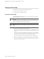
MX960 Ethernet Services Router
DC Power Supply
Installation Instructions
19 October 2007
Part Number: 530-017577-01
Revision 2
This document describes how to remove and replace a DC power supply on a Juniper
Networks MX960 Ethernet Services Router.
Contents
DC Power Supply ............................................................................................2
DC Power Supply Electrical Specifications ................................................2
DC Power Supply LEDs .............................................................................3
Replacing a DC Power Supply .........................................................................4
Removing a DC Power Supply ..................................................................4
Installing a DC Power Supply ....................................................................7
List of Technical Publications ........................................................................10
Requesting Support .......................................................................................16
Revision History ............................................................................................16
■
1
MX960 Ethernet Services Router DC Power Supply Installation Instructions
DC Power Supply
In the DC power configuration, the router contains either two or four DC power
supplies (see Figure 1 on page 2), located at the lower rear of the chassis in
slots PEM0 through PEM3 (left to right). You can upgrade your DC power system from
two to four power supplies. The DC power supplies in slots PEM0 and PEM2 provide
power to the lower fan tray, DPC slots 6 through 11, and SCB slots 1 and 2. The DC
power supplies in slots PEM1 and PEM3 provide power to the upper fan tray, DPC
slots 0 through 5, and SCB slot 0.
Four power supplies provide full redundancy. If a DC power supply fails, its redundant
power supply takes over without interruption.
Each DC power supply has a single DC input (–48 VDC and return) that requires a
dedicated 80 A (–48 VDC) circuit breaker for the maximum router hardware
configuration. For information about site power preparations and connecting the
router to power and ground, see the MX960 Ethernet Services Router Hardware Guide.
For DC power supply and power system electrical specifications, see Table 1 on page
3 and the MX960 Ethernet Services Router Hardware Guide.
Figure 1: DC Power Supply
DC Power Supply Electrical Specifications
Table 1 on page 3 lists the DC power supply electrical specifications. For DC power
system electrical specifications, see the MX960 Ethernet Services Router Hardware
Guide.
2
■
DC Power Supply
DC Power Supply
Table 1: DC Power Supply Electrical Specifications
Item
Specification
Maximum output power
2800 W
DC input voltage
Minimum: –40 VDC
Nominal: –48 VDC
Operating range: –40 to –72 VDC
NOTE: If the input voltage from the DC power source drops below
-37.5 to -39.5 VDC, the routing platform automatically shuts down.
During automatic shutdown, the circuit remains active. When the
input voltage returns to –43.0 to –44.00 VDC, the router
automatically starts up again and the system returns to normal
operation within 30 minutes. No operator intervention is required.
DC input current rating
70 A maximum @ –48 VDC (nominal operating voltage)
Internal Supplementary
Protector
80 A
DC Power Supply LEDs
Each DC power supply faceplate contains three LEDs that indicate the status of the
power supply (see Table 2 on page 3). The power supply status is also reflected in
two LEDs on the craft interface (see the MX960 Ethernet Services Router Hardware
Guide). In addition, a power supply failure triggers the red alarm LED on the craft
interface.
Table 2: DC Power Supply LEDs
Label
Color
State
Description
PWR OK
Green
Off
Power supply is not functioning normally. Check the INPUT OK LED for more
information.
On
Power supply is functioning normally.
Off
DC power supply circuit breaker is turned off.
On
DC power supply circuit breaker is turned on.
Off
DC input to the PEM is not present.
On
DC input is present, and is connected in correct polarity.
On
DC input is present, but connected in reverse polarity.
BREAKER
ON
INPUT OK
Green
Green
Amber
DC Power Supply
■
3
MX960 Ethernet Services Router DC Power Supply Installation Instructions
Replacing a DC Power Supply
To replace a DC power supply, use the following procedures:
■
Removing a DC Power Supply on page 4
■
Installing a DC Power Supply on page 7
Removing a DC Power Supply
The power supplies are located at the rear of the chassis. Each DC power supply
weighs approximately 3.8 lb (1.7 kg).
CAUTION: Do not leave a power supply slot empty for more than 30 minutes while
the router is operational. For proper airflow, the power supply must remain in the
chassis or a blank panel must be used in an empty slot.
NOTE: After powering off a power supply, wait at least 60 seconds before turning it
back on.
To remove a DC power supply, follow this procedure:
4
■
1.
Make sure that the voltage across the DC power source cable leads is 0 V and
that there is no chance that the cables might become active during the removal
process.
2.
Attach an electrostatic discharge (ESD) grounding strap to your bare wrist and
connect the strap to one of the ESD points on the chassis. For more information
about ESD, see the MX960 Ethernet Services Router Hardware Guide.
3.
Switch the circuit breaker on the power supply faceplate to the OFF position.
4.
Remove the clear plastic cover protecting the terminal studs on the faceplate.
5.
Remove the nuts and washers from the terminal studs (see Figure 2 on page 5).
(Use a 3/8–in. nut driver or pliers.)
Replacing a DC Power Supply
Replacing a DC Power Supply
Figure 2: Disconnecting Power Cables From the DC Power Supply
6.
Remove the cable lugs from the terminal studs.
7.
Loosen the captive screw on the cable restraint on the lower edge of the power
supply faceplate.
8.
Carefully move the power cables out of the way.
9.
While grasping the handle on the power supply faceplate with one hand, use
your other hand to pull the spring-loaded locking pin in the release lever away
from the chassis and turn the release lever counterclockwise until it stops (see
Figure 3 on page 6).
10. Let go of the locking pin in the release lever. Ensure that the pin is seated inside
the corresponding hole in the chassis.
11. Pull the power supply straight out of the chassis.
WARNING: Do not touch the power connector on the top of the power supply (see
Figure 4 on page 6). It can contain dangerous voltages.
Replacing a DC Power Supply
■
5
MX960 Ethernet Services Router DC Power Supply Installation Instructions
Figure 3: Removing a DC Power Supply
Figure 4: Top of the Power Supply Showing Midplane Connector
6
■
Replacing a DC Power Supply
Replacing a DC Power Supply
Installing a DC Power Supply
To install a DC power supply, follow this procedure (see Figure 5 on page 9):
1.
Ensure that the voltage across the DC power source cable leads is 0 V and that
there is no chance that the cable leads might become active during installation.
CAUTION: You must ensure that power connections maintain the proper polarity.
The power source cables might be labeled (+) and (–) to indicate their polarity. There
is no standard color coding for DC power cables. The color coding used by the external
DC power source at your site determines the color coding for the leads on the power
cables that attach to the terminal studs on each power supply.
2.
Attach an electrostatic discharge (ESD) grounding strap to your bare wrist and
connect the strap to one of the ESD points on the chassis. For more information
about ESD, see the MX960 Ethernet Services Router Hardware Guide.
3.
Switch the circuit breaker on the power supply faceplate to the OFF position.
4.
Ensure that the release lever below the empty power supply slot is engaged in
the counterclockwise, or unlocked, position (see Figure 5 on page 9).
If necessary, pull the spring-loaded locking pin in the release lever away from
the chassis and turn the release lever counterclockwise until it stops. Let go of
the locking pin in the release lever. Ensure that the pin is seated inside the
corresponding hole in the chassis.
5.
Using both hands, slide the power supply straight into the chassis until the power
supply is fully seated in the chassis slot. The power supply faceplate should be
flush with any adjacent power supply faceplates.
The small tab on the metal housing that is controlled by the release lever must
be inside the corresponding slot at the bottom of the power supply (see
Figure 5 on page 9). This tab is used to pull the power supply down in the
chassis slot, before the power supply is removed.
6.
While firmly pushing the handle on the power supply faceplate with one hand,
use your other hand to pull the spring-loaded locking pin in the release lever
away from the chassis and turn the release lever clockwise until it stops.
7.
Let go of the locking pin in the release lever. Ensure that the pin is seated inside
the corresponding hole in the chassis.
8.
Remove the clear plastic cover protecting the terminal studs on the faceplate.
9.
Remove the nuts and washers from the terminal studs.
10. Attach the lugs on the DC source power cables to the terminal studs, making
sure the cables are not touching or in the way of any router components (see
Figure 6 on page 10).
Replacing a DC Power Supply
■
7
MX960 Ethernet Services Router DC Power Supply Installation Instructions
■
Attach the positive (+) DC source power cable lug to the RTN (return)
terminal.
■
Attach the negative (–) DC source power cable lug to the –48V (input)
terminal.
NOTE: The DC power supplies in slots PEM0 and PEM1 must be powered by dedicated
power feeds derived from feed A, and the DC power supplies in slots PEM2 and PEM3
must be powered by dedicated power feeds derived from feed B. This configuration
provides the commonly deployed A/B feed redundancy for the system. For
information about connecting to DC power sources, see the MX960 Ethernet Services
Router Hardware Guide.
11. Secure each power cable lug to the terminal studs, first with the split washer,
then with the nut. Apply between 23 lb-in. (2.6 Nm) and 25 lb-in. (2.8 Nm) of
torque to each nut.
12. Loosen the captive screw on the cable restraint on the lower edge of the power
supply faceplate.
13. Route the positive and negative DC power cables through the left and right sides
of the cable restraint.
14. Tighten the cable restraint captive screw to hold the power cables in place.
15. Replace the clear plastic cover over the terminal studs on the faceplate.
16. Verify that the ground and power cabling are correct, that they are not touching
or blocking access to router components, and that they do not drape where
people could trip on them.
17. Switch the circuit breaker on the power supply to the ON position and observe
the status LEDs on the power supply faceplate. If the power supply is correctly
installed and functioning normally, the PWR OK, BREAKER ON, and INPUT OK
LEDs light steadily.
8
■
Replacing a DC Power Supply
Replacing a DC Power Supply
Figure 5: Installing a DC Power Supply
Replacing a DC Power Supply
■
9
MX960 Ethernet Services Router DC Power Supply Installation Instructions
Figure 6: Connecting DC Power to the Router
List of Technical Publications
Table 3 on page 10 lists the software and hardware guides and release notes for
Juniper Networks J-series, M-series, MX-series, and T-series routing platforms and
describes the contents of each document. Table 4 on page 15 lists the books included
in the Network Operations Guide series.
Table 5 on page 15 lists additional books on Juniper Networks solutions that you can
order through your bookstore. A complete list of such books is available at
http://www.juniper.net/books.
Table 3: Technical Documentation for Supported Routing Platforms
Book
Description
JUNOS Software for Supported Routing Platforms
10
Access Privilege
Explains how to configure access privileges in user classes by using
permission flags and regular expressions. Lists the permission flags
along with their associated command-line interface (CLI) operational
mode commands and configuration statements.
Class of Service
Provides an overview of the class-of-service (CoS) functions of the
JUNOS software and describes how to configure CoS features,
including configuring multiple forwarding classes for transmitting
packets, defining which packets are placed into each output queue,
scheduling the transmission service level for each queue, and
managing congestion through the random early detection (RED)
algorithm.
■
List of Technical Publications
List of Technical Publications
Table 3: Technical Documentation for Supported Routing Platforms (continued)
Book
Description
CLI User Guide
Describes how to use the JUNOS command-line interface (CLI) to
configure, monitor, and manage Juniper Networks routing
platforms. This material was formerly covered in the JUNOS System
Basics Configuration Guide.
Feature Guide
Provides a detailed explanation and configuration examples for
several of the most complex features in the JUNOS software.
High Availability
Provides an overview of hardware and software resources that
ensure a high level of continuous routing platform operation and
describes how to configure high availability (HA) features such as
nonstop routing (NSR) and graceful Routing Engine switchover
(GRES).
MPLS Applications
Provides an overview of traffic engineering concepts and describes
how to configure traffic engineering protocols.
Multicast Protocols
Provides an overview of multicast concepts and describes how to
configure multicast routing protocols.
Multiplay Solutions
Describes how you can deploy IPTV and voice over IP (VoIP)
services in your network.
Network Interfaces
Provides an overview of the network interface functions of the
JUNOS software and describes how to configure the network
interfaces on the routing platform.
Network Management
Provides an overview of network management concepts and
describes how to configure various network management features,
such as SNMP and accounting options.
Policy Framework
Provides an overview of policy concepts and describes how to
configure routing policy, firewall filters, and forwarding options.
Routing Protocols
Provides an overview of routing concepts and describes how to
configure routing, routing instances, and unicast routing protocols.
Secure Configuration Guide for Common Criteria
and JUNOS-FIPS
Provides an overview of secure Common Criteria and JUNOS-FIPS
protocols for the JUNOS software and describes how to install and
configure secure Common Criteria and JUNOS-FIPS on a routing
platform.
Services Interfaces
Provides an overview of the services interfaces functions of the
JUNOS software and describes how to configure the services
interfaces on the router.
Software Installation and Upgrade Guide
Describes the JUNOS software components and packaging and
explains how to initially configure, reinstall, and upgrade the JUNOS
system software. This material was formerly covered in the JUNOS
System Basics Configuration Guide.
System Basics
Describes Juniper Networks routing platforms and explains how
to configure basic system parameters, supported protocols and
software processes, authentication, and a variety of utilities for
managing your router on the network.
List of Technical Publications
■
11
MX960 Ethernet Services Router DC Power Supply Installation Instructions
Table 3: Technical Documentation for Supported Routing Platforms (continued)
Book
Description
VPNs
Provides an overview and describes how to configure Layer 2 and
Layer 3 virtual private networks (VPNs), virtual private LAN service
(VPLS), and Layer 2 circuits. Provides configuration examples.
JUNOS References
Hierarchy and RFC Reference
Describes the JUNOS configuration mode commands. Provides a
hierarchy reference that displays each level of a configuration
hierarchy, and includes all possible configuration statements that
can be used at that level. This material was formerly covered in
the JUNOS System Basics Configuration Guide.
Interfaces Command Reference
Describes the JUNOS software operational mode commands you
use to monitor and troubleshoot interfaces.
Routing Protocols and Policies Command
Reference
Describes the JUNOS software operational mode commands you
use to monitor and troubleshoot routing policies and protocols,
including firewall filters.
System Basics and Services Command Reference
Describes the JUNOS software operational mode commands you
use to monitor and troubleshoot system basics, including
commands for real-time monitoring and route (or path) tracing,
system software management, and chassis management. Also
describes commands for monitoring and troubleshooting services
such as class of service (CoS), IP Security (IPSec), stateful firewalls,
flow collection, and flow monitoring.
System Log Messages Reference
Describes how to access and interpret system log messages
generated by JUNOS software modules and provides a reference
page for each message.
J-Web User Guide
J-Web Interface User Guide
Describes how to use the J-Web graphical user interface (GUI) to
configure, monitor, and manage Juniper Networks routing
platforms.
JUNOS API and Scripting Documentation
12
JUNOScript API Guide
Describes how to use the JUNOScript application programming
interface (API) to monitor and configure Juniper Networks routing
platforms.
JUNOS XML API Configuration Reference
Provides reference pages for the configuration tag elements in the
JUNOS XML API.
JUNOS XML API Operational Reference
Provides reference pages for the operational tag elements in the
JUNOS XML API.
NETCONF API Guide
Describes how to use the NETCONF API to monitor and configure
Juniper Networks routing platforms.
■
List of Technical Publications
List of Technical Publications
Table 3: Technical Documentation for Supported Routing Platforms (continued)
Book
Description
JUNOS Configuration and Diagnostic Automation
Guide
Describes how to use the commit script and self-diagnosis features
of the JUNOS software. This guide explains how to enforce custom
configuration rules defined in scripts, how to use commit script
macros to provide simplified aliases for frequently used
configuration statements, and how to configure diagnostic event
policies.
JUNOS Enhanced Services Documentation
Getting Started Guide
Provides an overview, basic instructions, and specifications for
J-series Services Routers. The guide explains how to prepare your
site for installation, unpack and install the router and its
components, install licenses, and establish basic connectivity. Use
the Getting Started Guide for JUNOS Enhanced Services.
Interfaces and Routing Guide
Explains how to configure the interfaces on J-series Services Routers
running JUNOS Enhanced Services for basic IP routing with standard
routing protocols, ISDN backup, digital subscriber line (DSL)
connections, and class-of-service (CoS) classification for safer, more
efficient routing.
Security Configuration Guide
Explains how to configure J-series Services Routers running JUNOS
Enhanced Services in virtual private networks (VPNs) and multicast
networks; configure firewall NAT and ALGs; apply routing
techniques such as zones, policies, stateful firewall filters, and IP
Security (IPSec) tunnels; and configure screens and firewall
authentication
Administration Guide
Shows how to manage users and operations, monitor network
performance, upgrade software, change routing and secure
contexts, and diagnose common problems on J-series Services
Routers running JUNOS Enhanced Services.
Design and Implementation Guide
Provides guidelines and examples for designing and implementing
IP Security (IPSec) VPNs, firewalls, and routing on J-series routers
running JUNOS software with Enhanced Services.
Migration Guide
Provides instructions for migrating an SSG 300M-series or SSG
500M-series security device running ScreenOS software or a J-series
router running JUNOS software to JUNOS Enhanced Services.
Hardware Documentation
Hardware Guide
Describes how to install, maintain, and troubleshoot routing
platforms and components. Each platform has its own hardware
guide.
PIC Guide
Describes the routing platform's Physical Interface Cards (PICs).
Each platform has its own PIC guide.
DPC Guide
Describes the Dense Port Concentrators (DPCs) for all MX-series
routers.
JUNOScope Documentation
List of Technical Publications
■
13
MX960 Ethernet Services Router DC Power Supply Installation Instructions
Table 3: Technical Documentation for Supported Routing Platforms (continued)
Book
Description
JUNOScope Software User Guide
Describes the JUNOScope software graphical user interface (GUI),
how to install and administer the software, and how to use the
software to manage routing platform configuration files and monitor
routing platform operations.
Advanced Insight Solutions (AIS) Documentation
AIS Operations Guide
J-series Routing Platform Documentation
Getting Started Guide
Provides an overview, basic instructions, and specifications for
J-series routing platforms. The guide explains how to prepare your
site for installation, unpack and install the router and its
components, install licenses, and establish basic connectivity. Use
the Getting Started Guide for your router model.
Basic LAN and WAN Access Configuration Guide
Explains how to configure the interfaces on J-series Services Routers
for basic IP routing with standard routing protocols, ISDN backup,
and digital subscriber line (DSL) connections.
Advanced WAN Access Configuration Guide
Explains how to configure J-series Services Routers in virtual private
networks (VPNs) and multicast networks, configure data link
switching (DLSw) services, and apply routing techniques such as
policies, stateless and stateful firewall filters, IP Security (IPSec)
tunnels, and class-of-service (CoS) classification for safer, more
efficient routing.
Administration Guide
Shows how to manage users and operations, monitor network
performance, upgrade software, and diagnose common problems
on J-series Services Routers.
Release Notes
JUNOS Release Notes
Summarize new features and known problems for a particular
software release, provide corrections and updates to published
JUNOS, JUNOScript, and NETCONF manuals, provide information
that might have been omitted from the manuals, and describe
upgrade and downgrade procedures.
Hardware Release Notes
Describe the available documentation for the routing platform and
summarize known problems with the hardware and accompanying
software. Each platform has its own release notes.
JUNOScope Release Notes
Contain corrections and updates to the published JUNOScope
manual, provide information that might have been omitted from
the manual, and describe upgrade and downgrade procedures.
AIS Operations Release Notes
AIS ai-script Release Notes
J-series Services Router Release Notes
14
■
List of Technical Publications
Briefly describe Services Router features, identify known hardware
problems, and provide upgrade and downgrade instructions.
List of Technical Publications
Table 3: Technical Documentation for Supported Routing Platforms (continued)
Book
Description
JUNOS Enhanced Services Release Notes
Summarize new features for a particular release, identify known
hardware and software problems, provide information that might
have been omitted from the manuals, and provide upgrade and
downgrade instructions.
Table 4: JUNOS Software Network Operations Guides
Book
Description
Baseline
Describes the most basic tasks for running a network using Juniper
Networks products. Tasks include upgrading and reinstalling JUNOS
software, gathering basic system management information,
verifying your network topology, and searching log messages.
Interfaces
Describes tasks for monitoring interfaces. Tasks include using
loopback testing and locating alarms.
MPLS
Describes tasks for configuring, monitoring, and troubleshooting
an example MPLS network. Tasks include verifying the correct
configuration of the MPLS and RSVP protocols, displaying the status
and statistics of MPLS running on all routing platforms in the
network, and using the layered MPLS troubleshooting model to
investigate problems with an MPLS network.
MPLS Log Reference
Describes MPLS status and error messages that appear in the output
of the show mpls lsp extensive command. The guide also describes
how and when to configure Constrained Shortest Path First (CSPF)
and RSVP trace options, and how to examine a CSPF or RSVP
failure in a sample network.
MPLS Fast Reroute
Describes operational information helpful in monitoring and
troubleshooting an MPLS network configured with fast reroute
(FRR) and load balancing.
Hardware
Describes tasks for monitoring M-series and T-series routing
platforms.
Table 5: Additional Books Available Through http://www.juniper.net/books
Book
Description
Interdomain Multicast
Routing
Provides background and in-depth analysis of multicast routing using Protocol Independent
Multicast sparse mode (PIM SM) and Multicast Source Discovery Protocol (MSDP); details
any-source and source-specific multicast delivery models; explores multiprotocol BGP (MBGP)
and multicast IS-IS; explains Internet Gateway Management Protocol (IGMP) versions 1, 2, and
3; lists packet formats for IGMP, PIM, and MSDP; and provides a complete glossary of multicast
terms.
JUNOS Cookbook
Provides detailed examples of common JUNOS software configuration tasks, such as basic
router configuration and file management, security and access control, logging, routing policy,
firewalls, routing protocols, MPLS, and VPNs.
List of Technical Publications
■
15
MX960 Ethernet Services Router DC Power Supply Installation Instructions
Table 5: Additional Books Available Through http://www.juniper.net/books (continued)
Book
Description
MPLS-Enabled Applications
Provides an overview of Multiprotocol Label Switching (MPLS) applications (such as Layer 3
virtual private networks [VPNs], Layer 2 VPNs, virtual private LAN service [VPLS], and
pseudowires), explains how to apply MPLS, examines the scaling requirements of equipment
at different points in the network, and covers the following topics: point-to-multipoint label
switched paths (LSPs), DiffServ-aware traffic engineering, class of service, interdomain traffic
engineering, path computation, route target filtering, multicast support for Layer 3 VPNs, and
management and troubleshooting of MPLS networks.
OSPF and IS-IS: Choosing an
IGP for Large-Scale Networks
Explores the full range of characteristics and capabilities for the two major link-state routing
protocols: Open Shortest Path First (OSPF) and IS-IS. Explains architecture, packet types, and
addressing; demonstrates how to improve scalability; shows how to design large-scale networks
for maximum security and reliability; details protocol extensions for MPLS-based traffic
engineering, IPv6, and multitopology routing; and covers troubleshooting for OSPF and IS-IS
networks.
Routing Policy and Protocols
for Multivendor IP Networks
Provides a brief history of the Internet, explains IP addressing and routing (Routing Information
Protocol [RIP], OSPF, IS-IS, and Border Gateway Protocol [BGP]), explores ISP peering and
routing policies, and displays configurations for both Juniper Networks and other vendors'
routers.
The Complete IS-IS Protocol
Provides the insight and practical solutions necessary to understand the IS-IS protocol and how
it works by using a multivendor, real-world approach.
Requesting Support
For technical support, open a support case with the Case Manager link at
http://www.juniper.net/support/ or call 1-888-314-JTAC (from the United States, Canada,
or Mexico) or 1-408-745-9500 (from elsewhere).
Revision History
19 October 2007—530-017577-01 Revision 2. Corrected the DPC slot range supported
by power supplies PEM0 and PEM2.
12 March 2007—530-017577-01 Revision 1.
Copyright © 2007, Juniper Networks, Inc. All rights reserved.
Juniper Networks, the Juniper Networks logo, NetScreen, and ScreenOS are registered trademarks of Juniper Networks, Inc. in the United States and other
countries. JUNOS and JUNOSe are trademarks of Juniper Networks, Inc. All other trademarks, service marks, registered trademarks, or registered service
marks are the property of their respective owners.
Juniper Networks assumes no responsibility for any inaccuracies in this document. Juniper Networks reserves the right to change, modify, transfer, or
otherwise revise this publication without notice.
Products made or sold by Juniper Networks or components thereof might be covered by one or more of the following patents that are owned by or licensed
to Juniper Networks: U.S. Patent Nos. 5,473,599, 5,905,725, 5,909,440, 6,192,051, 6,333,650, 6,359,479, 6,406,312, 6,429,706, 6,459,579, 6,493,347,
6,538,518, 6,538,899, 6,552,918, 6,567,902, 6,578,186, and 6,590,785.
16
■
Requesting Support