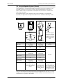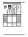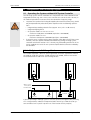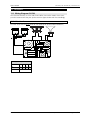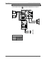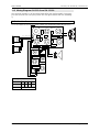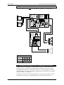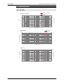
1
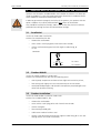
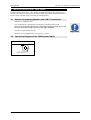
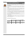
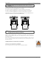
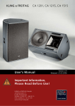
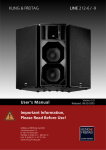
KLING & FREITAG
CA 1201, CA 1215, CA 1515
User's Manual
Important Information,
Please Read Before Use!
KLING & FREITAG GmbH
Junkersstrasse 14
D-30179 Hannover
PHONE 0 (049) 511- 969 97-0
FAX 0 (049) 511- 67 37 94
www.kling-freitag.de
Version 4.1
Released: 17.02.2015
User's Manual
KLING & FREITAG GMBH ©1998 --- 2015
CA 1201, CA 1215-6 /-9, CA 1515-6 /-9
Version 4.0, 17.02.2015
Page 2 of 54
User's Manual
CA 1201, CA 1215-6 /-9, CA 1515-6 /-9
Thank you for your decision to buy a Kling & Freitag product. To guarantee a
trouble-free operating of the equipment and to enable the KLING & FREITAG CA
speaker system to achieve its full potential, please read the operating instructions
carefully before use.
With the purchase of a CA system, you have acquired a speaker system with the
highest possible quality and performance capabilities.
As the owner of this system, you now have a versatile and highly professional tool
which, when operated properly, is a true pleasure to use.
Symbols in User's Manual
This symbol indicates the possibility of life-threatening danger and a
health risk for persons. Not following these instructions may result in
serious health problems including potentially fatal injuries.
Warning
This symbol indicates a possibly dangerous situation. Not following
these instructions may cause minor injuries or cause property damage.
Caution
This symbol gives instructions for the proper use of the described products. Not following these instructions may cause malfunctions or property damage.
Important
Information about this User's Manual
User's Manual CA 1201, CA 1215-6 /-9, CA 1515-6 /-9 Version 4.0, 17.02.2015
© by André Figula, Kling & Freitag GmbH, 1998 - 2015; all rights reserved.
All specifications in this manual are based on information available at the time of publishing for the features and safety guidelines of the described products.
Technical specifications, measurements, weights and properties are not guaranteed.
The manufacturer reserves the right to make product alterations within legal provisions
as well as changes to improve product quality.
All persons who use the speaker system must have this guide and all further
information for safe operations available to them during assembly, disassembly, and use.
We appreciate any input with suggestions and improvements for this manual.
Please send this to us at the following address:
[email protected] or to:
KLING & FREITAG GMBH Junkersstr.14 D-30179 Hannover
Phone +49 (0) 511 - 96 99 70 Fax +49 (0) 511 - 67 37 94
KLING & FREITAG GMBH ©1998 - 2015
Version 4.0, 17.02.2015
Page 3 of 54
User's Manual
CA 1201, CA 1215-6 /-9, CA 1515-6 /-9
Contents
Chapter
Page
1.
2.
General Instructions for Using Speakers
Product Descriptions and Versions
2.1 CA 1201
2.2 CA 1215-6
2.3 CA 1215-9
2.4 CA 1515-6
2.5 CA 1515-9
3. Important Notes for the Options ‘Outdoor’ and ‘Installation’
3.1 ‘Installation’
3.2 ‘Outdoor Mobile’
3.3 ‘Outdoor Installation’
4. Notes for Versions with ‘100V’ Option
4.1 Reasons for choosing Speakers with 100 V Transformers
4.2 Connecting Diagram of the 100V Speaker Inputs
5. Instructions for Suspending the Speakers
5.1 Using the ‘allsafe JUNGFALK’ Flying Points
6. Coverage Patterns of the CA Speakers
6.1 Changing the Coverage Pattern
7. Mounting Instructions for Speakers
7.1 Proper Arrangement of the Loudspeakers
7.2 Arrayed Speaker Systems (Cluster)
7.2.1 Horn not rotated
7.2.2 With rotated Horn
8. Wiring
8.1 Connecting the Speakon Connector to the Terminal
8.2 Avoiding Ground Loops
8.2.1 What is a Ground Loop?
8.2.2 Avoiding Ground Loops
9. Configurations and Connecting Diagrams
9.1 Operating the Systems without K&F System Controller
9.1.1 CA Systems in Full-Range Mode
9.1.2 Full Range Mode & Subwoofer with Crossover (XO)
9.2 Operations with K&F System Controller
10. Operating the Speakers
11. Crossovers
11.1 Wiring Diagram CA 1201
11.1.1 Version A
11.1.2 Version B
11.2 Wiring Diagram CA 1215-6 and CA 1215 -9
11.2.1 Version A
11.2.2 Version B
11.3 Wiring Diagram CA 1515-6 and CA 1515-9
11.3.1 Version A
11.3.2 Version B
KLING & FREITAG GMBH ©1998 --- 2015
Version 4.0, 17.02.2015
6
8
8
9
10
11
12
13
13
13
13
14
14
14
15
18
19
19
20
20
21
21
22
23
23
24
24
24
25
25
25
26
27
27
28
28
28
29
30
30
31
32
32
33
Page 4 of 54
User's Manual
CA 1201, CA 1215-6 /-9, CA 1515-6 /-9
Chapter
Page
12. Touching Up Damage to Paint / Changing the Front Foam
13. Technical Specifications
13.1 CA 1201
13.2 CA 1215-6
13.3 CA 1215-9
13.4 CA 1515-6
13.5 CA 1515-9
14. Measuring Charts
14.1 CA 1201
14.2 CA 1215-6
14.3 CA 1215-9
14.4 CA 1515-6
14.5 CA 1515-9
15. Dimensions
15.1 CA 1201, CA 1215-6 and CA 1215-9
15.2 CA 1201-M, CA 1215-6-M and CA 1215-9-M
15.3 CA 1201, CA 1215-6 and CA 1215-9 with Option ‘Installation’
15.4 CA 1515-6 and CA 1515-9
15.5 CA 1515-6 and CA 1515-9 with Option ‘Installation’
16. Accessories for the CA Systems
18. Supplied Safety and Mounting Instructions for Speakers and Accessories
KLING & FREITAG GMBH ©1998 - 2015
Version 4.0, 17.02.2015
33
34
34
35
36
37
38
39
39
41
43
45
47
49
49
49
50
51
51
52
Page 5 of 54
User's Manual
CA 1201, CA 1215-6 /-9, CA 1515-6 /-9
1. General Instructions for Using Speakers
Mounting the speakers
To prevent injury, the speakers must be securely placed on the floor or secured to the
wall according to the instructions on page 20 (Mounting Instructions for Speakers).
Please note that speakers can move as a result of vibrations. To prevent them from
falling from their mounted position, they must be secured properly. If the weight of
the speaker exceeds 20 kg then it is necessary for two people to carry it.
Warning
Speakers may only be suspended or mounted to walls or ceilings by qualified personnel.
The speakers must be hung by using at least two of the designated flying points. The
same applies when lifting and aligning the speakers.
Never use signal cables or power cords for suspending, aligning or securing the systems.
When laying the connecting cables, make sure that nobody can trip.
Never hang more than two speakers under one another without using the designated
Kling & Freitag rigging equipment.
Ensure that all installation connections comply with the applicable safety guidelines and
that the size and strength are sufficient. Further instructions are in our user's manual for
assembly equipment and in the general safety instructions for speakers and assembly
equipment.
For mobile and fixed installations, use only rigging equipment from KLING & FREITAG.
Make sure to observe the included safety and mounting instructions for loudspeakers
and accessories.
Speakers and rigging equipment must be visually examined at regular intervals. If
there are signs of wear, they must be replaced immediately. Furthermore, screwed
connections of supporting parts must be checked routinely.
Protecting the speakers / avoiding fire hazard
In general, audio signals should not be overdriven. This may be caused by mixing consoles,
equalizers, effect equipment, etc. and should be indicated on this equipment. When a power
amplifier is overloaded at the output (clipping), then the amplifier should activate a clipping
warning signal. Power amplifiers can also be overloaded at the input circuit without the
amplifier signalling the clipping, i.e. when there is not sufficient headroom in the input circuit. We, therefore, recommend turning up the power amplifiers all the way and adjusting
the level before the power amplifier in order to avoid overloading the input circuit. In any
case, the signal must be reduced as soon as it sounds unnaturally distorted.
To protect the speakers from being destroyed and to avoid fire hazard, they should only
be operated with professional power amplifiers with the following specifications:
− Integrated or preceding subsonic filter (approx. 30 Hz, min. 12 dB / octave)
− integrated clipping limiter
− for speaker models CA 1201 or CA 1215:
maximum rated power 500W@8Ω (equivalent 1000W@4Ω)
Warning
− for speaker model CA 1515:
maximum rated power 700W@8Ω (equivalent 1400W@4Ω)
If you wish to use a speaker with a power amplifier which does not fulfil these specifications, then the speaker should be controlled using a Kling & Freitag system controller with limiter function. This is the only way overloading and the risk of fire can be
avoided. The results of such a power amplifier defect cannot be avoided by the controller.
If power amplifiers have power ratings lower than mentioned above, then it is imperative that a clipping limiter is used to protect the speaker even if it is used with a Kling
& Freitag system controller.
For damage caused by overloading or use with power amplifiers other than those recommended above, Kling & Freitag GmbH does not assume warranty and excludes liability for
possible consequential damage.
KLING & FREITAG GMBH ©1998 --- 2015
Version 4.0, 17.02.2015
Important
Page 6 of 54
User's Manual
CA 1201, CA 1215-6 /-9, CA 1515-6 /-9
The following signals may damage the speakers
Important
−
Permanent high-pitched signals with high frequency, and continuous noise
from feedback.
−
Permanently distorted signals with high power.
−
Noises, which occur when the amplifier is on while equipment is being connected, disconnected or switched on.
Do not install speakers in any of the following places:
−
Where the speakers are permanently exposed to direct sunlight
−
Where the speakers are exposed to high moisture
−
Where the speakers are exposed to strong vibrations and dust.
Damage caused by the speakers' magnetic fields
Speakers are permanently surrounded by a magnetic field even when they are not
operating. Therefore, during transport and placement of the speakers, it is important
to ensure that there is always approx. 1 m between the speakers and magnetic data
media and computer/video monitors.
Preventing hearing damage
To prevent the risk of hearing damage, avoid being too close to operating speakers,
even if the volume level seems to be low enough. In general, volume levels over 90 dB
can cause hearing damage.
Caution
KLING & FREITAG GMBH ©1998 - 2015
Version 4.0, 17.02.2015
Page 7 of 54
User's Manual
CA 1201, CA 1215-6 /-9, CA 1515-6 /-9
2. Product Descriptions and Versions
2.1
CA 1201
Short description:
2-way full-range speaker system with 12" low-mid chassis and 1" high frequency
driver on a rotatable 90° x 60° CD horn. Homogeneous coverage and constant directivity starting at 1.2 kHz. Integrated crossover with self-resetting protection circuit
for low-mid and high frequency path.
Enclosure:
Trapezoidal enclosure with additional cluster angles, 15 mm birch plywood, highly
resistant structured grey or black finish, internal mounting flange, 5 ‘allsafe JUNGFALK’ flying points, 2 butterfly handles, highly permeable, ball proof steel grille with
exchangeable black acoustic foam.
Optional versions:
− CA 1201-M:
Enclosure with additional monitor angle
− CA 1201-100V:
100V version with 300 VA toroidal transformer
− CA 1201 --- ‘Installation’
Version for fixed installations
− CA 1201 --- ‘Outdoor Installation’ / ‘Outdoor Mobile’
Versions for outdoor use under roofs
− CA 1201-SP:
Version with integrated power amplifier technology (not for CA 1201-M)
'SP' speakers are shipped with a separate user's manual!
− Special finish in RAL colours
KLING & FREITAG GMBH ©1998 --- 2015
Version 4.0, 17.02.2015
Page 8 of 54
User's Manual
CA 1201, CA 1215-6 /-9, CA 1515-6 /-9
2.2
CA 1215-6
Short description:
2-way high-performance speaker system with 12" low-mid chassis and 1.5" high
frequency horn driver on a rotatable 65° x 50° CD horn. Homogeneous coverage and
constant directivity starting at 1.2 kHz. Integrated crossover with self-resetting protection circuit for high frequency path, delay time and phase optimisation.
Enclosure:
Trapezoidal enclosure with additional cluster angles, 15 mm birch plywood, highly
resistable structured grey or black finish, internal mounting flange, 5 ‘allsafe JUNGFALK’ flying points, 2 butterfly handles, highly permeable, ball proof steel grille with
exchangeable black acoustic foam.
Optional versions:
− CA 1215-6-M:
Enclosure with additional monitor angle
− CA 1215-6 100V:
100V version with 300 VA toroidal transformer
− CA 1215-6 - ‘Installation’
Version for fixed installations
− CA 1215-6 - ‘Outdoor Installation’ / ‘Outdoor Mobile’
Versions for outdoor use under roofs
− CA 1215-6-SP:
Version with integrated power amplifier technology (not for CA 1215-6-M)
'SP' speakers are shipped with a separate user's manual!
− Special finish in RAL colours
KLING & FREITAG GMBH ©1998 - 2015
Version 4.0, 17.02.2015
Page 9 of 54
User's Manual
2.3
CA 1201, CA 1215-6 /-9, CA 1515-6 /-9
CA 1215-9
Short description:
2-way high-performance speaker system with 12" low-mid chassis and 1.5" high frequency driver on a rotatable 90° x 50° CD horn. Homogeneous coverage and constant directivity starting at 1.0 kHz. Integrated crossover with self-resetting protection
circuit for high frequency path, delay time and phase optimisation.
Enclosure:
Trapezoidal enclosure with additional cluster angles, 15 mm birch plywood, highly
resistant structured grey or black finish, internal mounting flange, 5 ‘allsafe JUNGFALK’ flying points, 2 butterfly handles, highly permeable, ball proof steel grille with
exchangeable black acoustic foam.
Optional versions:
− CA 1215-9-M:
Enclosure with additional monitor angle
− CA 1215-9-100V:
100V version with 300 VA toroidal transformer
− CA 1215-9 - ‘Installation’
Version for fixed installations
− CA 1215-9 - ‘Outdoor Installation’ / ‘Outdoor Mobile’
Version for outdoor use under roofs
− CA 1215-9-SP:
Version with integrated power amplifier technology (not for CA 1215-9-M)
'SP' speakers are shipped with a separate user's manual!
− Special finish in RAL colours
KLING & FREITAG GMBH ©1998 --- 2015
Version 4.0, 17.02.2015
Page 10 of 54
User's Manual
CA 1201, CA 1215-6 /-9, CA 1515-6 /-9
2.4
CA 1515-6
Short description:
description :
2-way high-performance speaker system with 15" low-mid chassis and 1.5" high frequency driver on a rotatable 65° x 50° CD horn. Homogeneous coverage and constant directivity starting at 1.2 kHz. Integrated crossover with self-resetting protection
circuit for chassis and crossover, delay time and phase optimisation.
Enclosure:
Trapezoidal enclosure with additional monitor and cluster angles, 15 mm birch plywood, highly resistant structured grey or black finish, internal mounting flange, 5
‘allsafe JUNGFALK’ flying points, 2 butterfly handles, highly permeable, ball proof
steel grille with exchangeable black acoustic foam, non-abrasive plastic feet.
Optional versions:
− CA 1515-6-100V:
100V version with 300 VA toroidal transformer
− CA 1515-6 - ‘Installation’
Version for fixed installations
− CA 1515-6 - ‘Outdoor Installation’ / ‘Outdoor Mobile’
Version for outdoor use under roofs
− CA 1515-6-SP:
Version with integrated power amplifier technology (not for 1515-9-M)
'SP' speakers are shipped with a separate user's manual!
− Special finish in RAL colours
KLING & FREITAG GMBH ©1998 - 2015
Version 4.0, 17.02.2015
Page 11 of 54
User's Manual
2.5
CA 1201, CA 1215-6 /-9, CA 1515-6 /-9
CA 1515-9
Short description:
description:
2-way high-performance speaker system with 15" low-mid chassis and 1.5" high frequency driver on a rotatable 90° x 50° CD horn. Homogeneous coverage and constant
directivity starting at 1.0 kHz. Integrated crossover with self-resetting protection circuit
for chassis and crossover, delay time and phase optimisation.
Enclosure:
Enclosure:
Trapezoidal enclosure with additional monitor and cluster angles, 15 mm birch plywood, highly resistant structured grey or black finish, internal mounting flange, 5 ‘allsafe JUNGFALK’ flying points, 2 butterfly handles, highly permeable, ball proof steel
grille with exchangeable black acoustic foam, non-abrasive plastic feet.
Optional versions:
− CA 1515-9-100V:
100V version with 300 VA toroidal transformer
−
−
CA 1515-6 - ‘Installation’
Version for fixed installations
CA 1515-9 - ‘Outdoor Installation’ / ‘Outdoor Mobile’
Version for outdoor use under roofs
− CA 1515-9-SP:
Version with integrated power amplifier technology (not for 1515-9-M)
'SP' speakers are shipped with a separate user's manual!
− Special finish in RAL colours
KLING & FREITAG GMBH ©1998 --- 2015
Version 4.0, 17.02.2015
Page 12 of 54
User's Manual
CA 1201, CA 1215-6 /-9, CA 1515-6 /-9
3.
Important Notes for the Options ‘Outdoor’ and ‘Installation’
Speakers with the option ‘Outdoor Mobile’ and ‘Outdoor Installation’ have been optimised for outdoor use. They withstand temperature fluctuations in moderate climate
zones and do not accumulate condensation water.
In order to guarantee the longevity and safety of the speakers, the speakers with the
option ‘Outdoor’ must still be protected from direct effects of the weather.
Warning
They should be installed, for example, under a roof so that they also have sufficient
protection from driving rain from the side and direct sunlight.
3.1
‘Installation’
Version for fixed indoor installations.
Features like standard version but:
−
without feet and handles
−
seven stainless steel flying points with internal M10 threads,
−
stainless steel connecting terminal with single PG cable fitting, Ø
13 mm
Connector:
1bl
3.2
2+
bn
bl = blue
bn = brown
‘Outdoor Mobile’
Version for mobile outdoor use under roofs.
Features like standard version but with the following extras:
−
multi-layered, temperature and UV-resistant high-tech PU marine primer,
−
final coating with highly resistant structured 2K paint in RAL colours,
−
waterproofed diaphragms and electronic components protected against corrosion with protective coating.
3.3
‘Outdoor Installation’
Version for fixed outdoor installations under roofs.
Features like 'Outdoor Mobile', but:
−
without feet and handles.
−
seven stainless steel flying points with internal M10 threads
−
stainless steel grille
−
foam covering behind grille
−
visible screws made of stainless steel.
−
Stainless steel connecting terminal with single PG cable fitting, Ø 13 mm (connecting scheme see version ‘Installation’)
KLING & FREITAG GMBH ©1998 - 2015
Version 4.0, 17.02.2015
Page 13 of 54
User's Manual
CA 1201, CA 1215-6 /-9, CA 1515-6 /-9
4. Notes for Versions with ‘100V’ Option
Kling & Freitag speakers with ‘100V’ option are fitted with high-quality toroidal transformers. This serves to minimize loss of sound. Highly professional sound reinforcement
results can be achieved using 100 V Kling & Freitag speakers.
4.1
Reasons for choosing Speakers with 100 V Transformers
−
Reduction in conduction loss.
−
Easy installation of a loudspeaker network due to simple parallel wiring.
The sum of the output power of the individual speakers (stated as VA = W)
must not exceed the output power of the 100 V amplifier.
−
Speakers are galvanically isolated.
−
Speakers can be integrated into existing 100 V systems.
4.2
Important
Connecting Diagram of the 100V Speaker Inputs
300VA transformer
300VA
1+
2- IN 12+
0
all pins parallel to out
KLING & FREITAG GMBH ©1998 --- 2015
Version 4.0, 17.02.2015
Page 14 of 54
User's Manual
CA 1201, CA 1215-6 /-9, CA 1515-6 /-9
5. Instructions for Suspending the Speakers
The speakers may only be suspended by trained specialised personnel.
Pay attention to the required safety factors. Please follow the accompanying
safety and assembly instructions carefully as well as the corresponding national
safety regulations.
Warning
All sound systems used are to be secured against toppling or falling in the manner required by the carriers of the statutory accident insurances for studio or stage areas.
Appropriate directions can be found in BGV C1 or corresponding local national safety
guidelines.
Amongst other things, this regulation stipulates that mobile sound equipment must be
secured from falling from two separate points. Because no clear regulations are available to us regarding fixed installations, as a precaution, we stipulate always using a second independent safety point to secure Kling & Freitag products.
The equipment is to be secured using steel chains, ropes of steel wire, and similar
materials, which are designed for the particular load and, when taking into consideration possible dynamic forces (i.e. during falling), are of sufficient size. The safety factors for the securing equipment as well as the maximum admissible falling height of
20 cm according to BGV C1, which are defined in the regulations and norms valid
when this handbook was published, must be complied with.
Ensure that all connections are secured to prevent their detaching on their own and
that only admissible statically tested and sufficiently sized connecting devices, ropes
and chains are used.
The upper and bottom flying and securing point "VariPoints", the 'K&F eyebolt' and
the 'K&F Lifting Pin' are suitable for securing a secondary safety device according to
the German safety regulations BGV C1. The rear 'Varipoint' are only suitable for a
bracing of the loudspeaker.
Please heed the following specifications:
wire length
wire diameter
max. falling
height
Wire rope according to DIN EN
56927
1m
5mm
0.2m
Major Saveking®
safety wire
0.6m
3mm
0.2m
KLING & FREITAG GMBH ©1998 - 2015
Version 4.0, 17.02.2015
Page 15 of 54
User's Manual
CA 1201, CA 1215-6 /-9, CA 1515-6 /-9
1.1 Example 1: Rigging with K&F Adjustable Speaker Mount or K&F Ceiling Bracket
The letters with numbers indicate the particular fastening points, the numbers define
the necessary first and second rigging points, accordingly.
A1 and A2 = required 2 rigging points, connection speaker to inner bracket
B1 and B2 = required 2 rigging points, connection inner bracket to outer bracket
C1 and C2 = required 2 rigging points, connection outer bracket to cross beam
If the safety wire C2 is missing, then the requirement to have two independently acting pieces of equipment to prevent falling is not fulfilled!
C1
A1
B1
C1
A2
A1
B2
C2
A2
B1
B2
2.1 Example 2: Rigging without K&F Adjustable Speaker Mount or K&F
Ceiling Bracket with additional loudspeaker
Speaker systems, whether single or connected to one another, must always be secured to a second separate point, even if two rigging points are used for suspending
the speaker system!
Ensure that all connections are secured to prevent their detaching on their own and
that only admissible statically tested and sufficiently sized connecting devices, ropes
and chains are used.
A rigging with only one safety device is prohibited.
A safety at a rear suspension is prohibited.
The rear suspension point can only be used for bracing the speaker.
KLING & FREITAG GMBH ©1998 --- 2015
Version 4.0, 17.02.2015
Warnung
Page 16 of 54
User's Manual
CA 1201, CA 1215-6 /-9, CA 1515-6 /-9
Wrong:
• The suspended speaker weighs more than 50
kg. This exceeds the total load-bearing capacity of the upper flying points. As a result, a
maximum of 2 full-range systems may be
suspended under one another.
• The rear suspension point can only support
weights up to 30 kg. The flying point is thus
not an appropriate secondary device to prevent collapse if another speaker is mounted.
• The angle of the rope/chain in relation to the
top of the mounted speaker is less than 45°.
This causes the load on the flying points to
exceed the permissible level.
Right:
• A two-point suspension was selected. Each
speaker is secured with an additional safety
device.
• The suspended speaker weighs no more than
50 kg. This falls within the total load-bearing
capacity of the upper flying point.
• The angle of the rope/chain in relation to the
top of the mounted speaker is greater than
45°. This maintains a permissible load on the
flying points.
KLING & FREITAG GMBH ©1998 - 2015
Version 4.0, 17.02.2015
Page 17 of 54
User's Manual
5.1
CA 1201, CA 1215-6 /-9, CA 1515-6 /-9
Using the ‘allsafe JUNGFALK’ Flying Points
Single Stud Fitting
Used as fastener to the ‘allsafe
JUNGFALK’ flying point.
1.)
‘allsafe JUNGFALK’ flying point
Receptacle for special fasteners.
2.)
Take the single stud fitting in one
hand...
3.)
... and push the locking device up
against the spring tension.
4.)
Put the flat head of the holding
bolt into the guiding of the flying
point.
Release the locking device when
the single stud fitting is located in
the middle of the flying point.
Make sure that the locking device
clicks into place.
5.)
Warning
Check that the single stud fitting is
securely fastened and cannot be
pulled out.
KLING & FREITAG GMBH ©1998 --- 2015
Version 4.0, 17.02.2015
Page 18 of 54
User's Manual
CA 1201, CA 1215-6 /-9, CA 1515-6 /-9
6. Coverage Patterns of the CA Speakers
The mid-high systems can be operated in a vertical or horizontal (i.e. as a stage monitor) position. The coverage pattern of the speakers can be adapted to special needs by
a 90° rotatable horn.
The table below shows the coverage angles of a standing speaker: To determine the
coverage pattern of the high frequency horn, shine a flashlight through the front
covering at the level of the horn. You will find a silver stripe that determines the position and coverage angles of the horn.
DEFINITI
DEFINIT I ON:
Standing speaker:
Horn not rotated
Horn rotated
90° h x 60° v
65° h x 50° v
90° h x 50° v
65° h x 50° v
90° h x 50° v
60° h x 90° v
50° h x 65° v
50° h x 90° v
50° h x 65° v
50° h x 90° v
Model
CA 1201
CA 1215-6
CA 1215-9
CA 1515-6
CA 1215-9
6.1
Changing the Coverage Pattern
To turn the horn, follow these steps:
1) Remove the four grille mounting screws on the top and bottom of the speakers
with a 3 mm Allen key and remove the grille from the speaker enclosure.
2) Remove the screws from the high frequency horn (also using a 3 mm Allen key).
Loosen the high frequency horn by using both hands, palms to the outside, to
grasp into the horn and lift the horn with even pressure from the palms of your
hands towards the outside. Should the horn adhere to the foam rubber attached
below, release it using a screwdriver or something similar to gently lever it up.
3) Rotate the horn 90° and screw the horn on tightly again (do not force it!).
4) Screw the grille on tightly.
If the coverage angle needs to be changed often, make sure that the horn is not always
rotated in the same direction, as the connecting cables, when twisted, may cause the
contacts of the driver to become loose.
KLING & FREITAG GMBH ©1998 - 2015
Version 4.0, 17.02.2015
Page 19 of 54
User's Manual
CA 1201, CA 1215-6 /-9, CA 1515-6 /-9
7. Mounting Instructions for Speakers
Mount the speakers securely. To avoid injury or damage, always be sure to mount the
speakers securely so that they do not fall. Speakers, which are stacked, must be secured
with securing straps. When laying the connecting cables, make sure that nobody can
trip.
The stability of stacked systems (also valid for the use of stands and distance rods!) is
contingent upon the following stability requirement. These conditions must, therefore,
be guaranteed by the user:
Warning
Stacked systems may not fall over even if they are inclined by 10° in each direction. If this requirement is not fulfilled, then it is necessary to take steps to
achieve compliance. Possible measures include strapping it to an appropriate
base structure or fastening it using safety straps.
7.1
Proper Arrangement of the Loudspeakers
Be aware of the fact that the logical targeted alignment of this high quality speaker
system can lead to a significant qualitative increase in the acoustic result. It is not possible to make generalities about the alignment of specific systems because the room has
a substantial influence on the signal and the audible result.
As a rule, the mid- and high-transducers of loudspeakers should be mounted above the
audience's face value, so that the sound distribution cannot be shadowed.
In many cases it is advisable to mount a loudspeaker higher, so that the sound will be
distributed throughout the room more evenly. Low standing systems result in a greater
difference in volume between front and back seats than higher standing systems.
Please note that this is only a general guideline and the best possible result may vary
from room to room.
To simulate the correct alignment of the speakers beforehand, there are various programs such as ‘Ease’ or ‘Ulysses’. The Kling & Freitag speaker system data is available for
download on our website www.kling-freitag.de.
The following graphics will assist in making a rough estimate as to the distance range of
full-range systems. The graphics only take into consideration the sum of the direct
sound and not the influence of the room. Because of this there can, in some cases, be
noticeable deviation.
Distance range of SPL (direct sound level):
-18 dB
-12 dB
-6 dB
-24 dB
0 dB
2m 4m
8m
-34 dB
-30 dB
16m
KLING & FREITAG GMBH ©1998 --- 2015
32m
Version 4.0, 17.02.2015
50m
Page 20 of 54
User's Manual
CA 1201, CA 1215-6 /-9, CA 1515-6 /-9
7.2
Arrayed Speaker Systems (Cluster)
If the loudspeakers are operated through the optional K&F System Controller, we recommend to turn on the 'Top Low Cut' filter for clustered operation. Thus the frequency response for this application can be optimised (see also user’s manual of the
K&F System Controller).
When operating the systems without a K&F System Controller in a clustered configuration, the signal level of frequencies below 300 Hz should be reduced by 3-4 dB.
7.2.1 Horn not rotated
Winkel 2
Horn not
rotated
Winkel 3
Standing
speaker
A smaller angle 3
results in a smaller
vertical coverage
angle but increases
the sound power
level.
Winkel 1
Combination
CA 1201 with
CA 1201
CA 1215-6 with
CA 1215-6
CA 1215-6 with
CA 1215-9
CA 1215-9 with
CA 1215-9
CA 1515-6 with
CA 1515-6
CA 1515-6 with
CA 1515-9
CA 1515-9 with
CA 1515-9
Application
between the sides of the
speakers
between middle axes
Angle 1
45°-55°
Angle 2
55°-65°
not generally
recommended*
not generally
recommended*
30°
40°
35°
45°
40°-50°
50°-60°
not generally
recommended*
not generally
recommended*
30°
40°
35°
45°
40°-50°
50°-60°
not generally
recommended*
not generally
recommended*
Angle 3
20°-35
20°-30°
Increasing the horizonIncreasing the
Increasing the vertical
tal coverage angle, e.g. horizontal cover- coverage angle, e.g.
for wide audience
age angle and
for covering balcoplanes
sound power level nies or for increased
for larger distancsound power level
es
for larger distances
*If several 90° systems are clustered, unwanted interference effects may appear. As a
result, we do not generally recommend clustered configurations of CA 1201, CA 12159 and CA 1515-9 systems. If wide angles are to be covered, we recommend the use of
several 60° or 65° systems in one cluster.
KLING & FREITAG GMBH ©1998 - 2015
Version 4.0, 17.02.2015
Page 21 of 54
User's Manual
CA 1201, CA 1215-6 /-9, CA 1515-6 /-9
7.2.2 With rotated Horn
Winkel 2
Horn
rotated
Winkel 3
Standing
speaker
A smaller angle 3
results in a smaller
vertical coverage
angle but increases
the sound power
level.
Winkel 1
Combination
CA 1201 with
CA 1201
CA 1215-6 with
CA 1215-6
CA 1215-6 with
CA 1215-9
CA 1215-9 with
CA 1215-9
CA 1515-6 with
CA 1515-6
CA 1515-6 with
CA 1515-9
CA 1515-9 with
CA 1515-9
Application
Angle 1
Angle 2
Angle 3
25°
35°
Not recommended
30°-40°
30°-45°
20°
30°
Not recommended
30°-40°
30°-45°
Not recommended
Increasing the horizon- Increasing the hori- Increasing the vertital coverage angle, e.g.
zontal coverage
cal coverage angle,
for wide audience
angle and sound
e.g. for covering
planes
power level for
balconies or for
larger distances
increased sound
power level for
larger distances
KLING & FREITAG GMBH ©1998 --- 2015
Version 4.0, 17.02.2015
Page 22 of 54
User's Manual
CA 1201, CA 1215-6 /-9, CA 1515-6 /-9
8. Wiring
The speaker is equipped with two parallel Speakon connectors.
Make sure that all units are switched off and all controls are turned down before connecting your CA systems.
−
We recommend the use of high-quality speaker cables provided by KLING & FREITAG.
−
For connections to the power amplifier inputs, please use 2-pin shielded microphone
cable with high-quality connectors.
−
Avoid ground loops (see chapter 8.2 )
−
Please pay attention to the respective pin diagrams in this manual!
−
Make sure that the +/- polarity of the speakers at the amplifier is correct. When simultaneously using power amplifiers from different manufacturers, be sure to use the
correct specific pin configuration. It may be necessary to modify the pin configuration
on the power amplifiers or on the connectors leading to them.
−
Upon completing the wiring, ensure that the connected speaker channels are working in phase. To do so, use i.e. a phase checker. A phase error can also be recognized
when the connected channels are used simultaneously. During simultaneous use the
bass frequencies become notably quieter or the mid-frequencies such as voices cannot be located.
−
To avoid loss of power, the cables should have a minimum wire gauge of 2.5 mm² more for longer cabled distances. A minimum wire gauge can be easily calculated
with the following formula:
Important
Minimum Wire Gauge (mm²) =
Required Cable Length (m)
2 x Speaker Impedance (Ω)
If several loudspeakers are connected, the signal can be linked through from one loudspeaker to the next. Please make sure that the total impedance of the loudspeakers R(Ω) is
not lower than the minimal impedance indicated on the power amplifier.
1/R1 + 1/R2 + 1/R3 + ... = 1/Rtotal
8.1
Connecting the Speakon Connector to the Terminal
1.
2.
2.
3.
1.
KLING & FREITAG GMBH ©1998 - 2015
Version 4.0, 17.02.2015
Page 23 of 54
User's Manual
8.2
CA 1201, CA 1215-6 /-9, CA 1515-6 /-9
Avoiding Ground Loops
8.2.1 What is a Ground Loop?
Every component of a P.A. or Hi-Fi System has its own internal 0 V reference (ground).
This point is often connected to the protective earth connector (PE / Ground). If two or
more units are connected to one another with a line level audio cable, there may be a
ground connection through the ground of the power supply cable (yellow-green) as well
as through the shielding of the audio cable. The voltage difference between these two
ground points causes audible interference to come from the speaker
8.2.2 Avoiding Ground Loops
If there is a loud humming or buzzing after the CA System has been connected, then
check that a "ground loop" has not been built into the system. Some power amplifiers
and system controllers are equipped with a "Ground Lift" switch. Set these switches to
the "Lift" position one after the other. If the noise is still audible, check if,
1. the noise is caused by a ground loop before the power amplifiers / controllers
(e.g. mixing console, effects or equalizers).
2. the system or parts of the system are connected to an "unclean" power supply
- meaning one, which is also running large motors, or lighting systems. An
"unclean" supply voltage, electrostatic and electromagnetic fields can cause a
malfunction.
Please observe the following basic rules:
−
Never!!! try to avoid a ground loop by disconnecting or taping the ground
contact at the power connector! Extremely dangerous!
−
If possible, only use high-quality audio appliances with balanced signal outputs and
with power cables with PE connectors.
−
−
Use high-quality cables with good shielding.
The point of ground for all connected components should merge at one central
point. The power connections should lead out in a radial manner from one point
and not be linked from one unit to the next.
−
When installing appliances that create strong electrostatic or electromagnetic fields
(large transformers, switch-mode power supplies), maintain some distance from
other audio appliances. In extreme cases, the only solution is to create a completely
independent "audio ground"; in other cases, it is sufficient to connect a filter in
front of the audio equipment.
KLING & FREITAG GMBH ©1998 --- 2015
Version 4.0, 17.02.2015
Warning
Page 24 of 54
User's Manual
CA 1201, CA 1215-6 /-9, CA 1515-6 /-9
9. Configurations and Connecting Diagrams
9.1
Operating the Systems without K&F System Controller
The full-range systems can be used alone or in conjunction with a K&F subwoofer with
integrated crossover (e.g. SW 112-XO / SW 115D-XO SW 115E-XO or SW 118E-XO). In
this mode of operation the crossover limits the subwoofer's frequency range.
To protect the speakers from being destroyed and to avoid fire hazard, they should
only be operated with professional power amplifiers with the following specifications:
− integrated or preceding subsonic filter (approx. 30 Hz, min. 12 dB / octave)
− integrated clipping limiter
− for speaker model CA 1201 or CA 1215:
maximum rated power 500W@8Ω (equivalent 1000W@4Ω)
− for speaker model CA 1515:
maximum rated power 700W@8Ω (equivalent 1400W@4Ω)
If you wish to use a speaker with a power amplifier which does not fulfil these specifications, then the speaker should be controlled using a Kling & Freitag System
Controller with limiter function. This is the only way overloading and the risk of fire
can be avoided. The results of such a power amplifier defect cannot be avoided by
the controller.
Warning
9.1.1 CA Systems in Full-Range Mode
This mode of operation is ideal for speech applications and music applications without
the need for a high bass content. Should more bass be needed, the bass level can be
increased between 50 and 80 Hz at the mixing console.
INPUT e.g. from
mixer, AUX or
Connector Panel
OUTPUTS
INPUT CH 2
INPUT CH 1
+
CH 2
-
+
CH 1
If you are operating a mid-high system in a cluster (speakers arranged in close proximity)
or as a stage monitor, reduce the frequencies below 300 Hz by 3-4 dB! (The K&F System Controllers have a special ‘Top Low Cut’ filter function for this purpose.)
KLING & FREITAG GMBH ©1998 - 2015
Version 4.0, 17.02.2015
Page 25 of 54
User's Manual
CA 1201, CA 1215-6 /-9, CA 1515-6 /-9
9.1.2 Full Range Mode & Subwoofer with Crossover (XO)
In this mode of operation you can easily realise applications, where a higher bass level is
needed.
In this mode of operation be sure to use only amplifiers, which can handle speaker impedances down to 3 Ω.
Recommended combinations of CA systems, as described here, with K&F subwoofers:
Important
2 CA systems + 2- 4 x SW 112-XO
2 x SW 115D-XO
2 x SW 115E-XO
1 - 2 x SW 118E-XO
Switch To 'XO ON'
Switch To 'XO ON'
INPUT e.g. from
mixer, AUX or
Connector Panel
OUTPUTS
INPUT CH 2
INPUT CH 1
+
-
CH 2
+
CH 1
The switch ‘XO’ on the connecting terminal of the subwoofer must be at XO ‘ON’ for
this mode of operation:
Switch on the subwoofer’s connecting terminal
When using the mid-high systems in a cluster (speakers in close proximity), reduce the
frequencies below 300 Hz by 3-4 dB. (The K&F System Controllers have a special ‘Top
Low Cut’ filter function for this purpose.)
KLING & FREITAG GMBH ©1998 --- 2015
Version 4.0, 17.02.2015
Page 26 of 54
User's Manual
CA 1201, CA 1215-6 /-9, CA 1515-6 /-9
9.2
Operations with K&F System Controller
For optimal performance and operating safety we recommend using a K&F system
controller. Instructions for use, connecting diagrams and detailed descriptions of the
latest controller models ‘CD 24’ and ‘CD 44’ you can find in the corresponding user’s
manuals.
10. Operating the Speakers
− Switch off all equipment and turn down all level controls.
− Wire your CA systems.
Important
− Pay attention to the user’s manuals of your power amplifiers.
− Upon completing the wiring, ensure that the connected speaker channels are working in
phase. To do so, use i.e. a phase checker. A phase error can also be recognized when the
connected channels are used simultaneously. During simultaneous use the bass frequencies become notably quieter or the mid-frequencies such as voices cannot be located.
− Now switch on the peripheral equipment first (mixing console, effects etc.), followed by
the K&F system controller, if used, and the power amplifiers. Always use the before
mentioned switching order. Otherwise switching noises may damage the system.
− If there is interference, turn off all appliances in the reverse order and check all cable
−
connections.
Successively turn up the individual power amplifier channels and send a signal with low
volume to the system. Check to see if the desired signals are applied to the intended
speakers and make sure there is no interference. Make sure everything works properly, i.e.
if the signals come from the correct speaker paths (high signals from the tweeters, bass
signals from the bass speaker). Your system should now be ready for operation.
− Turning down the input level controls may not always prevent distortions in the input
section of the power amplifier, especially if this section has a relatively low headroom.
A clipping signal may not be displayed by the clipping indicator then. To prevent signal interruptions from protection circuits or damages to the speakers, turn the level
controls of the power amplifier to the maximum position, if possible. The output level
of the mixing console or the controller should be set to a level that doesn't overload
the power amplifiers.
− When turning off the system, the input controls for the power amplifiers should be
turned down first followed by the power switches of the amplifiers. After that, the
other appliances can be turned off.
− The crossovers of the CA systems are equipped with protection circuits for the high
frequency driver and the crossover itself. These circuits cut off the signal current when
highly overloaded. If the high speaker turns off, reduce the volume. After a few seconds, it will turn back on automatically.
KLING & FREITAG GMBH ©1998 - 2015
Version 4.0, 17.02.2015
Page 27 of 54
User's Manual
CA 1201, CA 1215-6 /-9, CA 1515-6 /-9
11. Crossovers
11.1 Wiring Diagram CA 1201
The crossover networks as of the end of 2003 differ from earlier models. Please compare the crossover built into your speaker with the figures below and wire accordingly:
11.1.1 Version A
CA 1201 & CA 1201-M up to serial no. 231 0000 20 29 (by the end of October 03)
Pin assignment Speakon NL4
+
-
/
/
‘IN’
1+
1-
2+ 2-
‘OUT’
parallel with ‘IN’
KLING & FREITAG GMBH ©1998 --- 2015
Version 4.0, 17.02.2015
Page 28 of 54
User's Manual
CA 1201, CA 1215-6 /-9, CA 1515-6 /-9
11.1.2 Version B
CA 1201 & CA 1201-M from serial no. 231 0000 20 30 (as of the end of October 03)
+
-
HF
Pin assignment Speakon NL4
+
-
/
/
‘IN’
1+ 1-
‘OUT’
parallel with ‘IN’
KLING & FREITAG GMBH ©1998 - 2015
2+ 2-
Version 4.0, 17.02.2015
Page 29 of 54
User's Manual
CA 1201, CA 1215-6 /-9, CA 1515-6 /-9
11.2 Wiring Diagram CA 1215-6 and CA 1215 -9
The crossover networks as of the end of 2003 differ from earlier models. Please compare the crossover built into your speaker with the figures below and wire accordingly.
11.2.1 Version A
CA 1215-6 and CA 1215-6-M up to serial number 23090007055 (before Sept. 03)
CA 1215-9 and CA 1215-9-M up to serial number 23090002675 (before Sept. 03)
IN + / link to XO 2
IN - / Link to XO 2
+
LF
-
-
+
HF
-
XO 2
IN -
IN +
Pin assignment Speakon NL4
+
-
/
/
‘IN’
1+
1-
2+ 2-
‘OUT’
parallel with ‘IN’
KLING & FREITAG GMBH ©1998 --- 2015
Version 4.0, 17.02.2015
Page 30 of 54
User's Manual
CA 1201, CA 1215-6 /-9, CA 1515-6 /-9
11.2.2 Version B
CA 1215-6 and CA 1215-6-M from serial number 23090007056 up (as of Sept. 03)
CA 1215-9 and CA 1215-9-M from serial number 23090002676 up (as of Sept. 03)
IN + / link to XO 2
IN - / Link to XO 2
XO 1
+
-
LF
XO 2
HF +
HF -
HF
+
Pin assignment Speakon NL4
+
-
/
/
‘IN’
1+ 1-
‘OUT’
parallel with ‘IN’
KLING & FREITAG GMBH ©1998 - 2015
2+ 2-
Version 4.0, 17.02.2015
Page 31 of 54
User's Manual
CA 1201, CA 1215-6 /-9, CA 1515-6 /-9
11.3 Wiring Diagram CA 1515-6 and CA 1515-9
The crossover networks as of the end of 2003 differ from earlier models. Please compare the crossover built into your speaker with the figures below and wire accordingly.
11.3.1 Version A
CA 1515-6 and CA 1515-9 up to serial number 23116000434 (before November 03)
XO 1
LF +
+
IN + / link to XO 2
LF
LF -
IN - / Link to XO 2
HF -
HF +
HF
+
XO 2
IN +
IN -
Pin assignment Speakon NL4
+
-
/
/
‘IN’
1+
1-
2+ 2-
‘OUT’
parallel with ‘IN’
KLING & FREITAG GMBH ©1998 --- 2015
Version 4.0, 17.02.2015
Page 32 of 54
User's Manual
CA 1201, CA 1215-6 /-9, CA 1515-6 /-9
11.3.2 Version B
CA 1515-6 and CA 1515-9 from serial number 23116000435 (as of November 03)
IN + / link to XO 2
IN - / Link to XO 2
+
-
LF
HF
+
Pin assignment Speakon NL4
+
-
/
/
‘IN’
1+ 1-
2+ 2-
‘OUT’
parallel with ‘IN’
12. Touching Up Damage to Paint / Changing the Front Foam
Although the PU structured paint used by KLING & FREITAG is impact proof and extremely resistant, we recommend using protective coverings or cases to help avoid
damaging the paint during i.e. continuous mobile use. If paint damage occurs despite
these precautions, it can be touched up by using commercial acrylic paint in the appropriate RAL colour of the speaker.
To replace the filter foam, send the front grille incl. foam to KLING & FREITAG GmbH.
Upon payment for expenses, the grille with the new covering will be returned.
KLING & FREITAG GMBH ©1998 - 2015
Version 4.0, 17.02.2015
Page 33 of 54
User's Manual
CA 1201, CA 1215-6 /-9, CA 1515-6 /-9
13. Technical Specifications
13.1 CA 1201
Loudspeaker
Design
2-way passive system, bass reflex tuning
Frequency range -10 dB
54 Hz - 19 kHz
Frequency range ±3 dB
65 Hz - 18 kHz
Coverage angles nominal
90° x 60° (hor. x vert.)
Directivity index (DI)
10 (+1.5/-1) 1.2 kHz - 16 kHz
Power handling
300 W nominal
Max. SPL
126 dB (SPL peak / 1 m)
Components
12‘‘ low-mid chassis
1)
1" high freq. driver with 40 mm titanium dome
on rotatable CD-horn
Crossover
1.8 kHz 18 dB / octave
self-resetting protection circuits for
12‘‘ and 1‘‘ chassis
Impedance (nominal)
8Ω
Connectors
2 x Speakon NL4MP (1+ / 1-)
Enclosure
Trapezoidal enclosure with additional cluster angles,
15 mm Finnish birch Multiplex with highly
resistant black structured paint (PU),
2 butterfly handles,
mounting flange K&M 19656,
ball proof front grille with exchangeable
black acoustic foam
Rigging
5 flying points 'allsafe JUNGFALK'
Dimensions (W x H x D)
380 x 605 x 375 mm
Weight
25 kg
Options
'48° monitor angle’ (K&F CA 1201 - M)
'100 Volt with 300 VA toroidal transformer’
‘Barrier strip instead of Speakon connectors'
'Outdoor Mobile' and 'Outdoor Installation'
‘Special finish in RAL colours’
Accessories
see catalogue or visit www.kling-freitag.de
KLING & FREITAG GMBH ©1998 --- 2015
Version 4.0, 17.02.2015
Page 34 of 54
User's Manual
CA 1201, CA 1215-6 /-9, CA 1515-6 /-9
13.2 CA 1215-6
Loudspeaker
Design
2-way passive system, bass reflex tuning
Frequency range -10 dB
62 Hz - 22 kHz
Frequency range ±3 dB
84 Hz - 19 kHz
Coverage angles nominal
65° x 50° (hor. x vert.)
Directivity index (DI)
12 (+1.5/-2) 1.2 kHz - 16 kHz
Power handling
400 W nominal
Max. SPL
130 dB (SPL peak / 1 m)
Components
12‘‘ low-mid chassis
1)
1.5‘‘ high freq. driver with 75 mm titanium dome
on rotatable CD-horn
Crossover
1.2 kHz 12 dB / octave,
self-resetting protection circuits for
12‘‘ and 1.5‘‘ chassis, all-pass filter for
delay time and phase optimisation
Impedance (nominal)
8Ω
Connectors
2 x Speakon NL4MP (1+ / 1-)
Enclosure
Trapezoidal enclosure with additional cluster angles,
15 mm Finnish birch Multiplex with highly
resistant black structured paint (PU),
2 butterfly handles,
mounting flange K&M 19656,
ball proof front grille with exchangeable
black acoustic foam
Rigging
5 flying points 'allsafe JUNGFALK'
Dimensions (W x H x D)
380 x 605 x 375 mm
Weight
31 kg
Options
'48° monitor angle’ (K&F CA 1215-6 - M)
'100 Volt with 300 VA toroidal transformer’
‘Barrier strip instead of Speakon connectors'
'Outdoor Mobile' and 'Outdoor Installation'
‘Special finish in RAL colours’
Accessories
KLING & FREITAG GMBH ©1998 - 2015
see catalogue or visit www.kling-freitag.de
Version 4.0, 17.02.2015
Page 35 of 54
User's Manual
CA 1201, CA 1215-6 /-9, CA 1515-6 /-9
13.3 CA 1215-9
Loudspeaker
Design
2-way passive system, bass reflex tuning
Frequency range -10 dB
58 Hz - 22 kHz
Frequency range ±3 dB
80 Hz - 19 kHz
Coverage angles nominal
90° x 50° (hor. x vert.)
Directivity index (DI)
10 (+2/-1) 1 kHz - 13 kHz
Power handling
400 W nominal
Max. SPL
129 dB (SPL Peak / 1 m)
Components
12‘‘ low-mid chassis
1)
1.5‘‘ high freq. driver with 75 mm titanium dome
on rotatable CD-horn
Crossover
1.2 kHz 12 dB / octave,
self-resetting protection circuits for
12‘‘ and 1.5‘‘ chassis, all-pass filter for
delay time and phase optimisation
Impedance (nominal)
8Ω
Connectors
2 x Speakon NL4MP (1+ / 1-)
Enclosure
Trapezoidal enclosure with additional cluster angles,
15 mm Finnish birch Multiplex with highly
resistant black structured paint (PU),
2 butterfly handles,
mounting flange K&M 19656,
ball proof front grille with exchangeable
black acoustic foam
Rigging
5 flying points 'allsafe JUNGFALK'
Dimensions (W x H x D)
380 x 605 x 375 mm
Weight
31 kg
Options
'48° monitor angle’ (K&F CA 1215-9 - M)
'100 Volt with 300 VA toroidal transformer’
‘Barrier strip instead of Speakon connectors'
'Outdoor Mobile' and 'Outdoor Installation'
‘Special finish in RAL colours’
Accessories
see catalogue or visit www.kling-freitag.de
KLING & FREITAG GMBH ©1998 --- 2015
Version 4.0, 17.02.2015
Page 36 of 54
User's Manual
CA 1201, CA 1215-6 /-9, CA 1515-6 /-9
13.4 CA 1515-6
Loudspeaker
Design
2-way passive system, bass reflex tuning
Frequency range -10 dB
47 Hz - 22 kHz
Frequency range ±3 dB
77 Hz - 19 kHz
Coverage angles nominal
65° x 50° (hor. x vert.)
Directivity index (DI)
12 (+1.5/-2) 1.2 kHz - 16 kHz
Power handling
500 W nominal
Max. SPL
132 dB (SPL peak / 1 m)
Components
15‘‘ low-mid chassis
1)
1.5‘‘ high freq. driver with 75 mm titanium dome
on rotatable CD-horn
Crossover
1.1 kHz 12 dB / octave, self-resetting
protection circuits for speakers and
crossover, all-pass filter for delay time and
phase optimisation
Impedance (nominal)
8Ω
Connectors
2 x Speakon NL4MP (1+ / 1-)
Enclosure
Multi-purpose enclosure with monitor and
cluster angles, 15 mm Finnish birch Multiplex
with highly resistant black structured paint (PU),
2 butterfly handles,
mounting flange K&M 19656,
ball proof front grille with exchangeable
black acoustic foam
Dimensions (W x H x D)
433 x 680 x 410 mm
Weight
36.4 kg
Options
'100 Volt with 300 VA toroidal transformer’
‘Barrier strip instead of Speakon connectors'
'Outdoor Mobile' and 'Outdoor Installation'
‘Special finish in RAL colours’
Accessories
KLING & FREITAG GMBH ©1998 - 2015
see catalogue or visit www.kling-freitag.de
Version 4.0, 17.02.2015
Page 37 of 54
User's Manual
CA 1201, CA 1215-6 /-9, CA 1515-6 /-9
13.5 CA 1515-9
Loudspeaker
Design
2-way passive system, bass reflex tuning
Frequency range -10 dB
58 Hz - 22 kHz
Frequency range ±3 dB
75 Hz - 19 kHz
Coverage angles nominal
90° x 50° (hor. x vert.)
Directivity index (DI)
10 (+2/-1) 1 kHz - 13 kHz
Power handling
500 W nominal
Max. SPL
131 dB (SPL peak / 1 m)
Components
15‘‘ low-mid chassis
1)
1.5‘‘ high freq. driver with 75 mm titanium dome
on rotatable CD-horn
Crossover
1.1 kHz 12 dB / octave, self-resetting
protection circuits for speakers and
crossover, all-pass filter for delay time and
phase optimisation
Impedance (nominal)
8Ω
Connectors
2 x Speakon NL4MP (1+ / 1-)
Enclosure
Multi-purpose enclosure with monitor and
cluster angles, 15 mm Finnish birch Multiplex
with highly resistant black structured paint (PU),
2 butterfly handles,
mounting flange K&M 19656,
ball proof front grille with exchangeable
black acoustic foam
Rigging
5 flying points 'allsafe JUNGFALK'
Dimensions (W x H x D)
433 x 680 x 410 mm
Weight
36.4 kg
Options
'100 Volt with 300 VA toroidal transformer
‘Barrier strip instead of Speakon connectors'
'Outdoor Mobile' and 'Outdoor Installation'
‘Special finish in RAL colours’
Accessories
see catalogue or visit www.kling-freitag.de
KLING & FREITAG GMBH ©1998 --- 2015
Version 4.0, 17.02.2015
Page 38 of 54
User's Manual
CA 1201, CA 1215-6 /-9, CA 1515-6 /-9
14. Measuring Charts
14.1 CA 1201
Frequency response
Impedance
Frequency response
100
100
90
31.6
80
10
70
20
100
1000
Frequency (Hz)
10000
Impedance (Ohm)
SPL (dB)
110
3,16
20000
Horizontal
Vertical
Beamwidth
360
-6dB Beamwidth (degrees)
300
240
180
120
60
0
20
100
1000
Frequency (Hz)
10000
20000
20
100
10
10
0
20
KLING & FREITAG GMBH ©1998 - 2015
100
1000
Frequency (Hz)
Version 4.0, 17.02.2015
10000
Directivity Factor (Q)
Directivity Index DI (dB)
Directivity
1
20000
Page 39 of 54
User's Manual
CA 1201, CA 1215-6 /-9, CA 1515-6 /-9
Horizontal coverage
180°
150°
120°
90°
60°
30°
0°
-30°
-60°
Attenuation (dB)
<3
3-6
6-9
9 - 12
-90°
12 - 15
-120°
15 - 18
-150°
> 18
-180°
125
250
500
1k
2k
4k
8k
16K
f [Hz]
Vertical coverage
180°
150°
120°
90°
60°
30°
0°
-30°
Attenuation (dB)
<3
3-6
6-9
-60°
9 - 12
-90°
12 - 15
-120°
15 - 18
-150°
-180°
125
250
500
1k
2k
4k
8k
> 18
16K
f [Hz]
KLING & FREITAG GMBH ©1998 --- 2015
Version 4.0, 17.02.2015
Page 40 of 54
User's Manual
CA 1201, CA 1215-6 /-9, CA 1515-6 /-9
14.2 CA 1215-6
Frequency response
Impedance
Frequency response
100
100
90
31.6
80
10
70
20
100
1000
Frequency (Hz)
10000
Impedance (Ohm)
SPL (dB)
110
3,16
20000
Horizontal
Vertical
Beamwidth
360
-6dB Beamwidth (degrees)
300
240
180
120
60
0
20
100
1000
Frequency (Hz)
10000
20000
100
10
10
0
20
100
1000
10000
Directivity Factor (Q)
Directivity Index DI (dB)
Directivity
20
1
20000
Frequency (Hz)
KLING & FREITAG GMBH ©1998 - 2015
Version 4.0, 17.02.2015
Page 41 of 54
User's Manual
CA 1201, CA 1215-6 /-9, CA 1515-6 /-9
Horizontal coverage
180°
150°
120°
90°
60°
30°
0°
-30°
-60°
Attenuation (dB)
<3
3-6
6-9
9 - 12
-90°
12 - 15
-120°
15 - 18
-150°
> 18
-180°
125
250
500
1k
2k
4k
8k
16K
f [Hz]
Vertical coverage
180°
150°
120°
90°
60°
30°
0°
-30°
Attenuation (dB)
<3
3-6
6-9
-60°
9 - 12
-90°
12 - 15
-120°
15 - 18
-150°
-180°
125
250
500
1k
2k
4k
8k
> 18
16K
f [Hz]
KLING & FREITAG GMBH ©1998 --- 2015
Version 4.0, 17.02.2015
Page 42 of 54
User's Manual
CA 1201, CA 1215-6 /-9, CA 1515-6 /-9
14.3 CA 1215-9
Frequency response
Impedance
Frequency response
100
100
90
31.6
80
10
70
20
100
1000
Frequency (Hz)
10000
Impedance (Ohm)
SPL (dB)
110
3,16
20000
Horizontal
Vertical
Beamwidth
360
-6dB Beamwidth (degrees)
300
240
180
120
60
0
20
100
1000
Frequency (Hz)
10000
20000
100
10
10
0
20
KLING & FREITAG GMBH ©1998 - 2015
100
1000
Frequency (Hz)
Version 4.0, 17.02.2015
10000
Directivity Factor (Q)
Directivity Index DI (dB)
Directivity
20
1
20000
Page 43 of 54
User's Manual
CA 1201, CA 1215-6 /-9, CA 1515-6 /-9
Horizontal coverage
180°
150°
120°
90°
60°
30°
0°
-30°
-60°
Attenuation (dB)
<3
3-6
6-9
9 - 12
-90°
12 - 15
-120°
15 - 18
-150°
> 18
-180°
125
250
500
1k
2k
4k
8k
16K
f [Hz]
Vertical coverage
180°
150°
120°
90°
60°
30°
0°
-30°
Attenuation (dB)
<3
3-6
6-9
-60°
9 - 12
-90°
12 - 15
-120°
15 - 18
-150°
-180°
125
250
500
1k
2k
4k
8k
> 18
16K
f [Hz]
KLING & FREITAG GMBH ©1998 --- 2015
Version 4.0, 17.02.2015
Page 44 of 54
User's Manual
CA 1201, CA 1215-6 /-9, CA 1515-6 /-9
14.4 CA 1515-6
Frequency response
Impedance
Frequency response
100
100
90
31.6
80
10
70
20
100
1000
Frequency (Hz)
10000
Impedance (Ohm)
SPL (dB)
110
3,16
20000
Horizontal
Vertical
Beamwidth
360
-6dB Beamwidth (degrees)
300
240
180
120
60
0
20
100
1000
Frequency (Hz)
10000
20000
100
10
10
0
20
100
1000
10000
Directivity Factor (Q)
Directivity Index DI (dB)
Directivity
20
1
20000
Frequency (Hz)
KLING & FREITAG GMBH ©1998 - 2015
Version 4.0, 17.02.2015
Page 45 of 54
User's Manual
CA 1201, CA 1215-6 /-9, CA 1515-6 /-9
Horizontal coverage
180°
150°
120°
90°
60°
30°
0°
-30°
-60°
Attenuation (dB)
<3
3-6
6-9
9 - 12
-90°
12 - 15
-120°
15 - 18
-150°
> 18
-180°
125
250
500
1k
2k
4k
8k
16K
f [Hz]
Vertical coverage
180°
150°
120°
90°
60°
30°
0°
-30°
Attenuation (dB)
<3
3-6
6-9
-60°
9 - 12
-90°
12 - 15
-120°
15 - 18
-150°
-180°
125
250
500
1k
2k
4k
8k
> 18
16K
f [Hz]
KLING & FREITAG GMBH ©1998 --- 2015
Version 4.0, 17.02.2015
Page 46 of 54
User's Manual
CA 1201, CA 1215-6 /-9, CA 1515-6 /-9
14.5 CA 1515-9
Frequency response
Impedance
Frequency response
SPL (dB)
100
100
90
80
10
70
20
100
1000
Frequency (Hz)
10000
Impedance (Ohm)
110
3,16
20000
Horizontal
Vertical
Beamwidth
360
-6dB Beamwidth (degrees)
300
240
180
120
60
0
20
100
1000
Frequency (Hz)
10000
20000
100
10
10
0
20
KLING & FREITAG GMBH ©1998 - 2015
100
1000
Version 4.0, 17.02.2015
10000
Directivity Factor (Q)
Directivity Index DI (dB)
Directivity
20
1
20000
Page 47 of 54
User's Manual
CA 1201, CA 1215-6 /-9, CA 1515-6 /-9
Horizontal coverage
180°
150°
120°
90°
60°
30°
0°
-30°
-60°
Attenuation (dB)
<3
3-6
6-9
9 - 12
-90°
12 - 15
-120°
15 - 18
-150°
> 18
-180°
125
250
500
1k
2k
4k
8k
16K
f [Hz]
Vertical coverage
180°
150°
120°
90°
60°
30°
0°
-30°
Attenuation (dB)
<3
3-6
6-9
-60°
9 - 12
-90°
12 - 15
-120°
15 - 18
-150°
-180°
125
250
500
1k
2k
4k
8k
> 18
16K
f [Hz]
KLING & FREITAG GMBH ©1998 --- 2015
Version 4.0, 17.02.2015
Page 48 of 54
User's Manual
CA 1201, CA 1215-6 /-9, CA 1515-6 /-9
15. Dimensions
15.1 CA 1201, CA 1215-6 and CA 1215-9
189.3 mm
pole mount
K&M 19656
Rigging Points
ANCRA Jungfalk
120030-31
183.2 mm
302.5 mm
605 mm
378.5 mm
375 mm
189.3 mm
[14.903 inch]
[14.763 inch]
[7.451 inch]
[6.772 inch]
172 mm
[23.819 inch]
[7.211 inch]
[11.909 inch]
172 mm
[6.771 inch]
[7.451 inch]
30°
5°
61.3 mm
256 mm
[2.412 inch]
[10.079 inch]
172 mm
[6.771 inch]
15.2 CA 1201-M, CA 1215-6-M and CA 1215-9-M
189.3 mm
[7.451 inch]
Plastic
Sliders
302.5 mm
[23.819 inch]
605 mm
374.1 mm
174.1 mm
[14.729 inch]
[6.855 inch]
74°
155°
48°
403 mm
136°
5°
[15.850 inch]
172 mm
[6.772 inch]
378.5 mm
[14.903 inch]
[11.909 inch]
Rigging Points
ANCRA Jungfalk
120030-31
pole mount
K&M 19656
Monitor Position
61.3 mm
256 mm
[2.412 inch]
[10.079 inch]
KLING & FREITAG GMBH ©1998 - 2015
Version 4.0, 17.02.2015
Page 49 of 54
User's Manual
CA 1201, CA 1215-6 /-9, CA 1515-6 /-9
15.3 CA 1201, CA 1215-6 and CA 1215-9 with Option ‘Installation’
189.3 mm
172 mm
[6.771 inch]
[7.451 inch]
183.2 mm
7 x Rigging Point M 10
302.5 mm
378.5 mm
375 mm
189.3 mm
[14.903 inch]
[14.763 inch]
[7.451 inch]
[11.909 inch]
605 mm
172 mm
[6.772 inch]
[23.819 inch]
[7.211 inch]
30°
5°
61.3 mm
256 mm
[2.412 inch]
[10.079 inch]
KLING & FREITAG GMBH ©1998 --- 2015
Version 4.0, 17.02.2015
Page 50 of 54
User's Manual
CA 1201, CA 1215-6 /-9, CA 1515-6 /-9
189.5 mm
[7.461 inch]
15.4 CA 1515-6 and CA 1515-9
216.8 mm
[8.536 inch]
Plastic
Sliders
pole mount
K&M 19656
340 mm
433.6 mm
411.3 mm
212.3 mm
[17.073 inch]
[16.195 inch]
[8.358 inch]
73°
155 °
454 mm
48°
137 °
5°
[17.890 inch]
189.5 mm
[7.461 inch]
[13.386 inch]
680 mm
[26.772 inch]
Rigging Points
ANCRA Jungfalk
120030-31
Monitor Position
62.9 mm
307.8 mm
[2.476 inch]
[12.120 inch]
189.5 mm
[7.461 inch]
15.5 CA 1515-6 and CA 1515-9 with Option ‘Installation’
216.8 mm
[8.536 inch]
340 mm
433.6 mm
411.3 mm
212.3 mm
[17.073 inch]
[16.195 inch]
[8.358 inch]
73°
155 °
5°
448 mm
48°
137 °
[17.653 inch]
189.5 mm
[7.461 inch]
[13.386 inch]
680 mm
[26.772 inch]
7 x Rigging Point M10
Monitor Position
62.9 mm
307.8 mm
[2.476 inch]
[12.120 inch]
KLING & FREITAG GMBH ©1998 - 2015
Version 4.0, 17.02.2015
Page 51 of 54
User's Manual
CA 1201, CA 1215-6 /-9, CA 1515-6 /-9
16. Accessories for the CA Systems
Tilt bracket CA 1201/CA1215
CA 1515
Cradle 1201/CA1215
Cradle 1515
Multi Cradle CA 1201/CA1215
Multi Cradle CA 1515
Wall mount,
tiltable up to 50 kg
Mounting bracket for versions with option ‚Installation’
KLING & FREITAG GMBH ©1998 --- 2015
Version 4.0, 17.02.2015
Page 52 of 54
User's Manual
CA 1201, CA 1215-6 /-9, CA 1515-6 /-9
Tilt Bracket
Stand Adapter
Distance Rod
Distance rod & application examples
with tilt bracket
TV-clamp
TV-spigot single stud
fitting
Further information is available in our downloadable catalogue at:
www.kling-freitag.de
KLING & FREITAG GMBH ©1998 - 2015
Version 4.0, 17.02.2015
Page 53 of 54
User's Manual
Fehler! Kein gültiger
gültiger Dateiname.
KLING & FREITAG GMBH ©1998 --- 2015
CA 1201, CA 1215-6 /-9, CA 1515-6 /-9
Version 4.0, 17.02.2015
Page 54 of 54