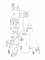
1
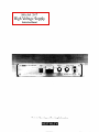
Model 247
High Voltage Supply
Instruction Manual
Contains Operating and Servicing Information
WARRANTY
Keithley Instruments, Inc. warrants this product to be free from defects in material and workmanship for a period of 1 year from date of
shipment.
Keithley Instruments, Inc. warrants the following items for 90 days from the date of shipment: probes, cables, rechargeable batteries,
diskettes, and documentation.
During the warranty period, we will, at our option, either repair or replace any product that proves to be defective.
To exercise this warranty, write or call your local Keithley representative, or contact Keithley headquarters in Cleveland, Ohio. You will
be given prompt assistance and return instructions. Send the product, transportation prepaid, to the indicated service facility. Repairs
will be made and the product returned, transportation prepaid. Repaired or replaced products are warranted for the balance of the original warranty period, or at least 90 days.
LIMITATION OF WARRANTY
This warranty does not apply to defects resulting from product modification without Keithley’s express written consent, or misuse of
any product or part. This warranty also does not apply to fuses, software, non-rechargeable batteries, damage from battery leakage, or
problems arising from normal wear or failure to follow instructions.
THIS WARRANTY IS IN LIEU OF ALL OTHER WARRAN TIES, EXPRESSED OR IMPLIED, INCLUDING ANY IMPLIED
WARRANTY OF MERCHANTABILITY OR FITNESS FOR A PARTICULAR USE. THE REMEDIES PROVIDED HEREIN ARE
BUYER’S SOLE AND EXCLUSIVE REMEDIES.
NEITHER KEITHLEY INSTRUMENTS, INC. NOR ANY OF ITS EMPLOYEES SHALL BE LIABLE FOR ANY DIRECT, INDIRECT, SPECIAL, INCIDENTAL OR CONSEQUENTIAL DAMAGES ARISING OUT OF THE USE OF ITS INSTRUMENTS AND
SOFTWARE EVEN IF KEITHLEY INSTRUMENTS, INC., HAS BEEN ADVISED IN ADVANCE OF THE POSSIBILITY OF
SUCH DAMAGES. SUCH EXCLUDED DAMAGES SHALL INCLUDE, BUT ARE NOT LIMITED TO: COSTS OF REMOVAL
AND INSTALLATION, LOSSES SUSTAINED AS THE RESULT OF INJURY TO ANY PERSON, OR DAMAGE TO PROPERTY.
Test Instrumentation Group, Keithley Instruments, Inc.
CHINA:
FRANCE:
GERMANY.
GREAT BRITAINz
ITALY:
JAPAN:
NE-S:
SWlTZERUNDz
Keithley
Keithley
Keithley
Keitbley
Keithley
Keithley
Keithley
Keithley
l
28775 Aurora Road Cleveland, Ohio 44139
l
l
(216) 248-0400 * Fax: (216) 248-6168
Instruments, Inc. * Holiday Inn Lido Office Building 4&4C Beijing, China, ICOO
8610-436-2871/2860 8610-436-2871
Instruments SARL * 3 All&e des Gamys B.P. 60 91122 Palaiseau C&dex * 01-60-11-51-55~ Fax: 01-60-H-77-26
Instruments GmbH Landsberge.rStr. 65.82110 Gennering 0 089-849307-O Fax: 089-84930759
Instruments, Ltd. The Minster 58 Portman Road Reading, Be&shire RG30 IEA 01734-575666 Fax: 01734-596469
Instruments SRL Vialc S. Gimignano 38 20146 hfilano. 02-48303008 Fax: 0248302274
Instruments Far East KK Sumiyoshi 24 Bldg., Room 201 2-24-2 Sumiyoshi-cho * Naka-ku, Yokohama 231 81-45-201-2246 Fax: 81-45-201-2247
Instruments BV. Awlingen West 49 4202 MS Gorinchem . Postbus 559 4200 AN Gorinchem 01830-35333 *Fax: 01830-30821
Instruments SA* Kriesbachstrasse4 8600 Diibendorf * 01-821-9444 Fax: 01-820-3081
l
l
l
l
l
l
l
l
l
l
l
l
l
l
l
l
l
l
l
l
l
l
l
l
l
Model 247 High Voltage Supply
Instruction Manual
Q 1990,
Keithley
Instruments,
Test Instrumentation
Inc.
Group
All rights reserved.
Cleveland,
December
Document
Ohio,
1992,
Number:
U.S.A.
Sixth Printing
31834
Rev. F
AU KeithIey product names are trademarks or registered trademarks of Keithley Instruments, Inc.
Other brand and product names are trademarks or registered trademarks of their respective holders.
SAFETY PRECAUTIONS
The following safety precautions
should be observed before using Model 247 High Voltage Supply.
The Model 247 High Voltage Supply is intended for use by qualified personnel who recognize shock hazards and are
familiar with the safety precautions required to avoid possible injury. Read over the instruction manual carefully before
using the instrument.
Exercise extreme caution when a shock hazard is present. Lethal voltages may be present on the test fixture or the supply
output connector. The American National Standards Jnstitute (ANSI) states the a shock hazard exists when voltage levels greater than3OV RMS or 42.4V peak are present. A good safety practice is to expect that hazardous voltage is present
in any unknown circuit before measuring.
Inspect the connecting
cables, test leads, and jumpers for possible wear, cracks, or breaks before each use.
For maximum safety, do not touch the voltage supply, test fixture, test cables or any other insfnunents while power is
applied to the circuit under test. Turn off all power and discharge any capacitorsbefore
connecting or disconnecting
cables or jumpers.
Do not touch any object which could provide a current path to the common side of the circuit under test or power line
(earth) ground. Always make measurements with dry hands while standing on a dry, insulated surface capable of withstanding the voltage being measured.
Instrumentation
and accessories
should not be connected to humans.
The L
symbol on a Model 247 indicates that 1OOOVor more may be present on the terminals. Refer to the Model 247
Instruction Manual.
Model 247
High Voltage Power Supply
OUTPUT:
Voltage: 0 to 3kV DC
Currentz6mA DC maximum.
Polarity: Positive or negative with respect to chassis.
ACCUI&4CY: (W-28°C): f (0.25% of setting t 1.5V DC) from 1% to 100% of maximum
output voltage.
RESOLUTION: Dial graduations of 200mV.
STABILITY: &O.Ol%of setting/hr.; fo.OZ%of setting/b hrs., at constant temperature after
r+hour warm-up.
TEMPEIUTURE COEFFICIENT (W’-18°C& 28”-50°C): sOppm/“C
LINE REGULATIONz 0.001% voltage change for 10% line variation.
LOAD REGULATION: 0.005% voltage change from no load to full load.
RIPPLEANDNOISE:3.5mVrms,lOmVp-p@3kV,6mA;lmV~,3mVp-p@lkV,lmA,
lOHz-1OOkHz
SE’ITLING TIME: 4 seconds to within 1V with full resistive load.
OVERLOAD PROTECTIONr Short circuit proof, arc protected, self restoring.
METER Monitors voltage output.
ENVIRONMENT:
Operating: 0’ to 50°C, 0 to 80% relative humidity up to 35°C
Storage: -40° to 75°C
CONNECTORz Rear panel, MI-IV Type LJG931/U.
POWER: 90-125V/180-25OV,50-6OHz,13OVA.
DIMENSIONS,WEIG~:483mmwidex89mmhighx273~deep(l9inx3~/~in.x103/4
in.), excluding handles. Four holes spaced for rack mounting. Net weight 5.9kg (13 Ibs.).
ACCESSORIES SUPPLIEIX Instruction manual, UG932/U mating connector, mounting
feet for bench operation.
Specifications subject to change without notice.
Table of Contents
SECTION 1 -
General Information
1.1
PURPOSEOFEQUIPMENT
1.2
DESCRIPTION
1.3
SPECIFICATIONS
1.4
sAFETYsYMEioLsANDTERMs..
1.5
W~INFoRMATION....................................................l-
SECTION 2 2.1
....................................................
FRONTl?ANELCONTROLSANDTERMlNALS
REAR PANEL CONNECTORS
2.4
l?REPAlK!JONFORUSE
2.5
INPUTPOWER
2.6
CURRENTLIMITING
27
HIGH VOLTAGE
2.8
APPLICATIONS
Application
2
AND TERMINALS
2-l
....................................
.....................................
.....................................................
..2..2..2-
2-4
..........................................
of 247 to Resisfivify
Measurements
2.8.3
Application
of 247 with Ionization Chambers
3
2-3
...............................................................
Application
3
2-3
........................................................
......................................................
OUTPUT
of 247 wit& Photomultipliers
1
2-2
...............................................................
2.8.2
2-4
......................................
2-4
.......................................
2-4
Theory of Operation
3.1
FUNCTIONALDESCRTMTON
3.2
CIRCUtTDESCIUI’TION
....................................................
......................................................
3-l
..3-
1
Maintenance
4.1
INTRODUcTloN
..............................................................
4.2
RECOMMENDED
TEST EQUIPMENT
4.3
PREPARATION
FORMEAS
4.4
CALIBRATION
ADJUSTMENTS
4.5
PERFORMANCETESTS
4.6
TROUJ3LESHOOTlNG
SECTION 5 -
l- 1
..............................................................
2.3
SECTION 4 -
l-l
................................................
Operation
INSTALLATION
SECTION 3 -
1
l-l
.............................................................
2.2
2.8.1
..I-
................................................................
Replaceable
..............................................
UREMENTS
............................................
..................................................
.........................................................
PROCEDURE
.. f. ...........................................
4-l
4-l
4-2
4-2
4-2
4-3
Parts
..............................................................
5.1
INTRODUCTION
5.2
ORDERINGINFORMATION
5.3
FACTORYSERVICE............................................................5-
.....................................................
5-l
5-l
1
List of Tables
SECTION 4 Table 41
Maintenance
Recommended
Test Equipment
. . . . . . . . . . . . . . . . . . . . . . . . . . . . . . . . . . . . . . . . . . . . . . . 41
List of Illustrations
SECTION 2 -
Operation
.....................................................
Figure 2-1
Model 247 Front Panel
Figure 2-2
Figure 2-3
......................................................
Mode1247RearPanel
..............................................
Connector and Cable Assembly
Figure 2-4
Figure 2-5
PhotomultiplierCircuit...................................Resistivity Measurement ....................................................
Figure 2-6
Ionization
SECTION 3 Figure 3-l
SECTION 4 Figure 41
Chamber Circuit ..................................................
2-2
2-2
2-4
.................
2-4
2-4
24
Theory of Operation
High Voltage Power Supply Block Diagram
. . . . . . . . . . . . . . . . . . . . . . . . . . . . . . . . . . . . . 3-l
Maintenance
Model 247 Exploded View
. . . . . . . . . . . . . . . . . . . . . . . . . . . . . . . . . . . . . . . . . . . . . . . . . . 44
SECTION 1
General Information
1 .I
PURPOSE
OF EQUIPMENT
The Model 247 is a regulated precision laboratory high
voltage power supply. It provides the low noise, excellent line regulation and high stability that are essential for
the most rigid measurement requirements.
The unit is fully enclosed and designed to mount in a
standard 19” rack. The unit may also be used in benchtop
applications using the rubber feet supplied.
1.3
SPECIFICATIONS
For Model247 detailed specifications,
cations that precede this section.
1.2
DESCRIPTION
The Model 247 is a precision regulated linear power supply with a maximum output voltage of 3kV. The units
consist of a DC power supply which converts the AC line
power to a low DC voltage and a DC converter which
generates the high DC output voltage. Low voltage electronic solid-state circuitry is mounted on the plug-in PCB
100, and the high voltage assembly is fully encapsulated
for reliable, arc-free, operation.
1.4
refer to the specifi-
SAFETY SYMBOLS AND TERMS
Safety symbols used in this manual are as follows:
Thesymbol Q ’ on the instrument denotes that the user
should refer to the operating instructions.
The symbol
on the instrument denotes that 1OOOVor
more may be present on the terminal(s).
This stable, low noise high voltage power supply features
front panel digital voltage metering and calibrated direct
reading front panel controls, and a polarity selector
switch. The rear panel features a HV output connector
line power plug, fuse, and a voltage selector switch. The
unit is arc and short circuit protected for safe, reliable operation
The WARNING used in this manual explains
that could result in personal injury or death.
dangers
The CAUTION used in this manual
that could damage the instrument.
hazards
explains
l-l
SECTION
1
General Information
1.5
WARRANTY INFORMATION
The warranty is given on the inside front cover of this Instruction Manual. If there is a need to exercise the Warranty, contact the factory to determine the proper action
to be taken.
l-2
NOTE
Attempting to repair or tampering with the
unit while still under warranty (less than 12
months since date of shipment> will void the
warranty. All in-warranty repairs should be
sent to the factory.
SECTION2
Operation
2.1
INSTALLATION
WARNING
This unit outputs hazardous voltage that
could cause injury or death. Do not connect
to line power unless ground (GND) and output high are properly connected.
Figure 2-l shows the mounting and clearance dimensions as well as the controls and connectors on the front
and rear panels. Rubber feet and screws are supplied
with each unit. For benchtop use, remove the four comer
screws and install the four rubber feet using the new
screws.
2.2
FRONT PANEL CONTROLS AND
TERMINALS
Polarity Switch -The polarity switch sets the output for
positive or negative polarity. Also, it switches the output
voltage off.
CAUTION
A two-second delay in the center OFF position is required when switching polarity.
Voltage Switch - The Voltage switch sets the output
voltage in increments of 500V from OV to 2OOOV.
Voltage Dial - The Voltage dial is a 10 turn digital dial
that supplements the Voltage switch setting by up to
1ooov.
Power Switch -A rocker switch turns the line power on
or off to the entire instrument. The rocker switch has a
built-in pilot lamp that is lit when the power switch is on.
WARNING
Before turning the power on to the instrument, make sure the voltage switch and dial
are properly set. Monitor the output on the
meter when the power is on.
Output Meter -The
output meter monitors the output
voltage. Meter operation is independent of the AC input
power; therefore, it reads the output at all times.
NOTE
The output voltage is the sum of the Voltage
dial and the Voltage switch.
2-l
SECTION 2
Operation
2.3
REAR PANEL CONNECTORS AND
TERMINALS
GND -The case ground screw (GND) is to be connected
to the measurement system common.
Output Connector - The output connector is a h4lW
type UG931/U connector. It mates with a h4HY type
UG932/U connector.
jFigure 2-l.
Model 247 Front Panel
Figure 2-2.
Model 247 Rear Panel
2-2
Fuse -The
line power fuse (Slo-Blo) is rated 1.6A, 250V
for 90-127V AC operation and 0.8A, 250V for 180~254V
AC operation.
Line Voltage Selector - The line voltage selector selects
the appropriate line voltage 90-127VAC or MO-254V AC.
Line Plug - The recessed line plug accepts a three-wire
female line plug for line power.
SECTTON=!
Operaf ion
2.4
PREPARATION
Perform the following
247 .-tor use:
FOR USE
procedure
to prepare the Model
1. Set the Model 247 for proper line voltage operation
as specified in paragraph 2.5.
2. Connect a ground wire from case ground (on rear
panel) to the measuring system common.
3. Set the front panel controls to:
A. Power switch - OFF
B. Polarity switch - OFF
C. Output voltage switch - 0
D. lOtumdigitaldial000 (full counterclockwise)
4. Plug the line cord into the power line with a threewire receptacle to maintain proper case ground.
WARNING
This unit is equipped with a three-wire
grounded line cord. This must be used with a
three-wire receptacle where the “third wire”
is connected to earth ground, otherwise personal injury or death may occur.
5. Connect the output of the Model 247 to the circuit.
Use a properly rated coaxial cable with the supplied
MHV type UG932/U mating connector to insure
good circuit connections and safe operation. Refer to
paragraph 2.6.
6. Set the Polarity switch to the desired polarity.
7. Turn on the power to the instrument. With actual
load and output voltage, allow one hour for warm
UP8. Increase the Voltage switch slowly to reach the approximate desired voltage. Then trim the voltage
with the Voltage dial until the desired voltage level
is obtained.
WARNING
Always turn power OFF and verify that the
Model 247’s output meter reads OV DC, before connecting or removing any equipment.
External circuits may retain High Voltage after the Model 247 has been turned off. Discharge any residual voltage before connecting or removing any equipment.
2.5
lector switch on the rear panel selects either 90-127V
(11OV setting) or 180~254V (22OV setting) operation.
INPUT POWER
The AC input line voltage required to operate the instrument is 90-127V or 180~254V. The recessed line voltage se-
The line fuse ratings are as follows:
Line
Voltage
90-127VAC
180-254VAC
2.6
Fuse Rating
1.6A, 25OV, slow blow
5x2On-m
O.SA, 25OV, slow blow,
5x2Omm
Keithley
Part No.
FU-96-7
Fu-96-6
CURRENT LIMITING
The Model 247 includes a current limiting circuit that
automatically drops the output voltage to a safe level
when the rated output current is exceeded by 20%. Refer
to the Maximum Current specification when operating
the unit at reduced output voltages or when operating in
a current limit mode for capacitor charging.
2.7
HIGH VOLTAGE OUTPUT
The high voltage output connector is located on the rear
panel (output LO is connected to chassis). A MHV type
UG932/U shielded mating connector is supplied with
each unit. Assembly insinrctions for the connector are
listed below.
1. Gently cut through the outer insulation without cutting the shield.
2. Using a sharp point, unravel the shield braid.
3. Clean off all traces of graphite.
4. Cut the center insulation to the proper length capproximately 3/8”). Cut the center conductor to approtiately
l/8”.
5. Solder center conductor to male pm. Cut the braid
back so it fits around the connector (see Figure 2-3).
6. Assemble as in Figure 2-3.
WARNING
When the High Voltage Output is not in use,
turn off the power and cover the output connector with the supplied cover cap.
2-3
SECTION 2
tance materials may be measured. Flexible materials such
as PVC, rubber or paper may be tested with the Model
6105 Resistivity Adapter as shown.
-1
Figwe 2-3.
2.8
)t3/32
UG-932RI Ccnn.
Voltage Rating to 5kV
Connector and Cable Assembly
I
The Model 247 is especially useful since it is low-noise
and well-regulated,
allowing the more sensitive electrometer ranges to be used when measuring high quality
insulators. The front panel polarity switch makes
it easy
to check for non-linearity (polarity sensitivity).
APPLICATIONS
The following are four examples of typical applications
of theMode 247, related to the low current capabilities of
electrometers and picoammeters.
2.8.1
Application of 247 with
Photomultipliers
The electron-multiplier
requires up to 200 volts per stage
and may have 10 to 14 stages. Thus, a totalsupply voltage
up to 3OOOVmay be needed. The overall sensitivity or
gain is very responsive to changes in supply voltage. For
this reason the long-term stability of the supply must be
excellent. The specified stability of the Model 247 is valid
after one-hour warm up- Warm up takes one hour with
a&.& load and output voltage.
Warning: Chassis of test
firiure must be connected to
a safety earth ground.
?igure 2-S.
2.8.3
Resisfivity Measuremenf
Application of 247 with Ionization
Chambers
The electrodes must have a bias voltage of several hundred volts to enable them to collect ions. This voltage
must be very steady since fluctuations would be capacitively coupled to the picoammeter and cause spurious
readings. The excellent line and load stabilities of the
Model 247 easily meet this need,
Figure 2-4.
Pho fomulfiplier Circuit
-------1
CentralElectrode
2.8.2
I
Application of 247 to Resistivity
Measurements
Shield Electrode
------
To find resistitity of insulating materials, a known voltage is applied to a sample of the material. The resulting
current is measured with a picoammeter or electrometer.
With a source voltage of 1000 volts or more, higher resis-
2-4
1 Figure 2-6.
Ionizdion Chamber Circuif
SECTION3
Theory of Operation
3.1
FUNCTIONAL DESCRIPTION
High
Voltage
OUtpUt
Figure 3-1 is a block diagram of the Model 247. The schematic diagram is located in Section 5, Replaceable Parts.
When reading through the Theory of Operation for the
Model 247, it will be helpful to refer to the schematic dia-
H.V.
Isolation
gram-
The circuit uses a DC-DC converter which converts low
voltage DC power to a high voltage DC output. This output voltage is highly regulated and filtered and can be
varied by the front panel controls. The input to the DCDC converter is obtained from internal low voltage
power supplies powered by AC line input.
Figure 3-1.
3.2
An oscillator determines the high frequency (approximately 2OkHz) at which all amplification high voltage
transformation,
rectification and filtering occurs- The
amplification is a function of a control voltage which performs the function of control and regulation. A sample of
the output voltage is compared against a reference voltage in the sensing circuit- The sensing circuit generates
the control voltage to set and maintain a fixed high voltage output.
High VoZtagePower Supply Block Diagram
CIRCUIT DESCRIPTION
The AC input line is converted to the B+ (36VDC) supply
and regulated kl2V low voltage power supplies. The B+
supply is a filtered full wave rectifier circuit located on
the chassis. The regulated low voltage power supply circuit (+12VI consists of a rectifier circuit located on Tl and
output regulators located on PCB-100.
The output of the oscillator circuit which is amplified in
the AGC amplifier, is a function of the control voltage developed at the output of the error amplifier.
3-I
SECTION 3
Theory
ofOperation
The encapsulated high voltage assembly includes a high
voltage transformer, rectifier or multiplier circuits, ripple
filter and sensing circuit. These are all critical custom designed and encapsulated components.
A sample of the high voltage DC output is fed to the output voltage sensing circuit, and is compared to a com-
3-2
mand voltage. Output voltage control is obtained by
varying the command voltage fed to the error amplifier.
The error amplifier compares the command voltage and
the signal from the output voltage sense circuit. Any differences causes a correction in the gain control of the
AGC amplifier. The command voltage is controlled by
the front panel controls; The reference and reference control and buffer provide a stable -5VDC to the front panel
output voltage controls.
SECTION4
Maintenance
4.1
death if normal safety precautions
observed.
INTRODUCTION
Section 4 contains information required for the maintenance of Model 247 units. It is organized around the verification procedure used to determine that the equipment
is operating to specifications.
are not
WARNING
To prevent a shock hazard, remove the line
cord and all test leads from the instrument
before removing any cover.
WARNING
The procedures in this section are for use
only by qualified service personnel. Do not
perform these procedures unless qualified
to do so. Many of the steps in this section
may expose you to potentially lethal voltages that could result in personal injury or
A
B
C
D
E
P
G
RECOMMENDED TEST EQUIPMENT
The recommended test equipment required to test and
maintain the Model 247 is listed in Table 4-1.
Recommended
Test Equipment
Description
Specifications
Manufacturer
Model
Oscilloscope
Digital Voltmeter
Variable Auto Transformer
Voltage Divider
Load Resistor
AC Viewing Circuit
Power Line Ammeter
lOMH2
-001%
3234
1000 to 1
-
Phillips
Keithley
General Radio
Julie Research
Clarostat
.I%
Valhalla Scientific
2000
r
Item
Table 41.
4.2
192
3030-5118
HV-10
VP-50-k-5Ok-50M
4-l
SECTION
4
Maintenance
HV
0
I
Potentiometer R178 is an Overload Adjustment. To calibrate this adjustment set the Model 247 for full load and
full voltage (3000V at 6mA) by using the load resistor (E)
on the output. Adjust R178 until the voltage drops off and
then back off of R178 approximately l/8 of a turn.
Potentiometer R173 is a Frequency Adjustment. To calibrate this adjustment set the Model 247 for full load and
full voltage (3000V at 6mA) by using the load resistor (E)
on the output. Adjust R173 for minimum AC power line
current.
4.3
PREPARATION FOR
MEASUREMENTS
Connect the HIGH VOLTAGE OUTPTJT of the Model
247 to the high voltage terminal of the DC voltage divider (D) and to the capacitor input of the AC viewing circuit (F). The low voltage terminal of the DC divider
should be connected to the digital voltmeter input, and
the AC viewing circuit output connected to the oscilloscope input. Make sure that a good ground is connected
to all instruments, viewing circuits and the Model 247.
After the ground has been checked, adequate safety precautions have been taken, and the output voltage controls set at zero, input power can be applied. The AC input should be applied through the variable autotransformer, which should be initially set for 115 or 230 volts output, as appropriate.
4.4
CALIBRATION ADJUSTMENTS
WARNING
To prevent a shock hazard, remove the
power cord and all test leads from the Model
247 before removing any cover.
Remove the top cover of the Model 247. Set the Volts
switch to 0. Set the Volts dial to read 1000. Adjust the Reference Adjust Potentiometer (R172) of PCB 100 (see Figure 4-l) for an output voltage of 1000 volts.
Set the Volts dial to read 10 (with the Volts switch still at
0). Adjust the Offset Adjust Potentiometer (R171) for an
output voltage of 10 volts. Set all front panel voltage controls for 3000 volt output and readjust the Reference Adjust Potentiometer 01172) if necessary.
42
Adjustment is not complete. The following performance
tests are used to determine that the unit meets all of its
specifications.
4.5
PERFORMANCE TESTS
Check to assure that the procedures
have been followed.
in paragraph
NOTE
Performance tests may be performed
doing the calibration.
4.3
without
Turn the front panel output volts control fully clockwise
until the reading on the digital voltmeter indicates maximum output from the Model 247.
Connect one end of the high voltage load resistor to
ground and the other end to a shorting stick (1 ft. insulated stick to which the load resistor is attached). Then,
with the shorting stick, connect the load resistor across
the high voltage output and observe the change in output
voltage. During this no load to full load test, the digital
voltmeter reading should not change by more than
0.005%.
With the load connected as above, observe the AC ripple
voltage on the oscilloscope. The ripple should be less
than the specified peak-to-peak ripple under this condition of full load and maximum output voltage.
Vary the autotransformer
to produce an AC line input
change of +lO% to the power supply, and again observe
the change in digital voltmeter reading. This change
should be less than 0.001%.
SECTION 4
Maintenance
Additional line and load regulation and ripple measurements may be performed at other voltage levels using the
same procedure outlined above. This should not usually
be necessary. Satisfactory test data at maximum output
voltage and the full range of voltage control generally indicate that satisfactory test data will be obtained at all
voltage levels. However, full range testing is performed
at the factory on each unit prior to shipment.
4.6
TROUBLESHOOTING PROCEDURE
A Model 247 High Voltage Power Supply consists of easily replaceable plug-in printed circuit boards, and a main
chassis assembly which includes the high voltage circuitry. The basic troubleshooting
procedure consists of
determining which of these assemblies is defective. Removal of the top cover provides access to the printed circuit board and high voltage components. The printed circuit board is secured by four screws to the bottom of the
chassis.
No further disassembly is required for troubleshooting
purposes. Make sure all test instruments are grounded,
either to the high voltage connector shield, or directly to
the chassis, prior to the application of input power to the
unit. The following procedures should then be followed.
Remove connector/cable from I’303 on PCB300 (see Figure 4-l for location). This leaves only the low voltage B+
and the unregulated +20 volt power supplies operable.
Turn on the AC line power and measure the DC voltage
obtained across R101. (See Figure 4-l for location.) This
voltage should be approximately +41VDC. If this voltage
differs by more than lS%, the power transformer, or
PCBlOO is probably defective.
If the B+ supply is operating properly, check for unregulated tiOVDC output accessible across C103(+) and
C131(-) on PCBlOO. The + voltages should be of equal
magnitude to within 5% and within the range of 16 to
24VDC. If the magnitude and tracking are not within the
range specified, this circuitry is probably defective.
If all of the low voltage power supplies are operating
properly, turn off input power, insert connector to P303,
turn all voltage controls to zero, follow the PREPARATION FOR MEASUREMENTS
procedure in paragraph
4.3, and turn the line power back on
If output voltage can be obtained, but the unit does not
properly regulate or the front panel control does not operate properly, P,CB 100 is probably defective.
If no output voltage is obtainable, test for AC drive to the
base of transistor Ql or Q2 located on the rear of the unit.
If drive is present, the high voltage assembly or transistors are probably defective.
It is recommended that the unit be returned to the factory
for the repair of the high voltage assembly. Specify model
number and serialnumber in all correspondence with the
factory.
4-3
SECTION 4
Mainfenance
R171
Power
Switch
..-.-
RI73
R178
R172
y!;z;
Assembly
output
\InltanP
SECTION5
Replaceable Parts
5.1
INTRODUCTION
Operational spares to support the Model 247 are available from the factory. It is recommended that common
electronic components (i.e. resistors, capacitors, transistors, etc.) be purchased from local electronics distributors. These parts are called out on the schematic diagrams
located on the following pages.
5.2
ORDERING INFORMATION
To place an order or to obtain information concerning replacement parts, contact your Keithley representative or
the factory. See inside front cover for addresses. When ordering, include the following information:
1.
2.
3.
4.
5.
Instrument Model Number
Instrument Serial Number
Parts Description
Circuit Description (if applicable)
PartNumber
5.3
FACTORY SERVICE
If the instrument is to be returned to the factory for service, please complete the Service Form which follows this
section, and return it with the instrument.
Table 5-1.
Model 247 Replacement
Parts
Description
Part Number
Printed Circuit Card (PCB 100)
Printed Circuit Card (PCB 300)
109641
208329
High Voltage module
Power transformer
Bridge rectifier
HV connector
HV Mating connector
Meter
rower switch
Output Voltage switch assembly
Polarity switch
Rubber bumper
308028
40152
ED1 #l?K 10
UG 931 /U
UG 932/U
309206-l
212JGlB60X03
301317
204737
H.H. Smith #2192
5-1
WI-
Service Form
Date
Serial No.
Model No.
Name and Telephone No.
Company
List all control settings, describe problem and check boxes that apply to problem.
a
u
m IEEE failure
m Obvious problem on power-up
Q
Batteries and fuses are OK
B
u
a
Checked all cables
Front panel operational
Analog output follows display
Particular range or function bad; specify
Ci Intermittent
All ranges or functions are bad
Display or output (check one)
Drifts
a
Unable to zero
m Unstable
0
Will not read applied input
a
Certificate of calibration required
5
5
Overload
u
Calibration only
0
Data required
(attach any additional sheets as necessary)
Show a block diagram of your measurement
Also, describe signal source.
system including all instruments
Where is the measurement
(factory, controlled laboratory, out-of-doors,
being performed?
etc.)
Ambient temperature?
What power line voltage is used?
Other?
Relative humidity?
Any additional information.
connected (whether power is turned on or not).
(If special modifications
have been made by the user, please describe.)
“F
Test Instrumentation Group
Keithley Instruments, Inc.
28775 Aurora Road
Cleveland, Ohio 44 139
Printedin the U.S.A.