1
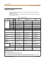
Digital Key Telephone Systems
Installation
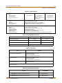
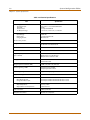
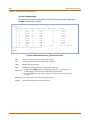
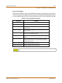
Issue
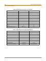
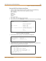
Release Date
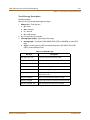
Changes
1.0
10-01
Initial Release
1.1
4-02
Incorporates minor revisions for correctness and clarity
1.2
3-03
Page
Enhancements allow increased system capacity.
3-43
ISDN and T1 Clocking material has been revised.
New line of telephone instruments has been added.
1.3
11-03
3-67
4-55
3-76
4-40
4-30
3-86
DTIBL Module added
Adds Type of Service function to VoIP Maint & Troubleshooting section
1.4
3-04
IP Phones added (includes Wallmounts, AC/DC adapter, & RSGM)
RSGM software upgrade procedure added.
IP Phone Software Upgrade procedure added.
Door Box feature added.
1.5
5-04
Additional telephone instruments can be used.
--
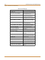
1.6
6-04
Incorporates minor revisions for correctness and clarity
--
1.7
9-04
Flash-based Voice Mail Interface Board is added.
2.0
1-05
Ethernet port is functional.
Table 2-3: System Capacity updated to reflect Feature Package 2 enhancements.
2.1
7-05
VoIP24 Card is added.
2.2
12-05
Hard Drive-based Voice Mail Interface Board has been added.
3-61
3-19
2-6
3-40
3-62
LIFE SUPPORT APPLICATIONS POLICY
VODAVI Technology, Inc. products are not authorized for and should not be used within Life
Support applications. Life Support systems are equipment intended to support or sustain life
and whose failure to perform when properly used in accordance with instructions provided
can be reasonably expected to result in significant personal injury or death.
VODAVI Technology, Inc. warranty is limited to replacement of defective components and
does not cover injury to persons or property or other consequential damages.
Copyright © 2001 VODAVI Technology, Inc.
All Rights Reserved
This material is copyrighted by VODAVI Technology, Inc., and may be duplicated by Authorized Dealers only.
Any unauthorized reproductions, use or disclosure of this material, or any part thereof, is strictly prohibited
and is a violation of the Copyright Laws of the United States (17 U.S.C. Section 101 et. seq.).
VODAVI reserves the right to make changes in specifications at any time and without notice. The information
furnished by VODAVI in this material is believed to be accurate and reliable, but is not warranted to be true in
all cases.
XTS is a registered trademark of VODAVI Technology, Inc.
mlj/2005
Hearing Aid Compatibility
Regulatory Information (U.S.A.)
The Federal Communications Commission (FCC)
established rules to allow the direct connection of the
XTS-IP to a telephone network. Certain actions must be
undertaken or understood before the connection of
customer provided equipment is completed.
Telephone Company Notification
Before connecting the XTS-IP to the telephone network,
the local serving telephone company must be given
advance notice of intention to use customer provided
equipment, and must be provided with the following
information:
Telephone Numbers
The telephone numbers to be connected to the system.
XTS-IP System Information
The Ringer Equivalence Number is also located on
the KSU: 1.3B
The USOC jack required for direct interconnection
with the telephone network: RJ11C
FCC Registration Numbers:
For systems configured as a key system: (button
appearances) KF: 5JYKOR-45504-KF-E
For systems configured as a Hybrid system: (dial
access codes) MF: 5JYKOR-45505-MF-E
Incidence of Harm
If the telephone company determines that the customer
provided equipment is faulty and possibly causing harm
or interruption to the telephone network, it should be
disconnected until repairs can be made. If this is not
done, the telephone company may temporarily
disconnect service.
Changes in Service
The local telephone company may make changes in its
communications facilities or procedures. If these
changes affect the use of the XTS-IP or compatibility
with the network, the telephone company must give
written notice to the user to allow uninterrupted service.
Maintenance Limitations
Maintenance on the XTS-IP System must be performed
only by the manufacturer or its authorized agent. The
user may not make any changes and/or repairs except as
specifically noted in this manual. If unauthorized
alterations or repairs are made, any remaining warranty
and the software license for the system will be voided.
All XTS-IP Digital Terminals are Hearing Aid Compatible,
as defined in Section 68.316 of Part 68 FCC Rules and
Regulations.
UL/CSA Safety Compliance
The XTS-IP System has met all safety requirements and
was found in compliance with the Underwriters
Laboratories (UL) 1459. This system is authorized to bear
the “NRTL/C” marking.
Notice of Compliance
The XTS-IP System complies with rules regarding
radiation and radio frequency emissions by Class A
computing devices. In accordance with FCC Standard 15
(Subpart J), the following information is supplied to the
end user:
“This equipment generates and uses RF energy
and if not installed and used in accordance with
the Instruction Manual, may cause interference to
Radio Communications. It has been tested and
found to comply with the limits for a Class A computing
device, pursuant to Subpart J of Part 15 of the FCC Rules,
which are designed to provide reasonable protection
against such interference, when operated in a commercial
environment. Operation of this equipment in a residential
area is likely to cause interference, in which case the user, at
his own expense, will be required to take whatever
measures may be required to correct the interference.”
“WARNING: Handling the cord on this product will
expose you to lead, a chemical known to the State of
California to cause [cancer, and] birth defects or other
reproductive harm. Wash hands after handling.”
Toll Fraud and DISA Disclaimer
“While this device is designed to be reasonably secure
against intrusions from fraudulent callers, it is by no
means invulnerable to fraud. Therefore, no express or
implied warranty is made against such fraud including
interconnection to the long distance network.”
“While this device is designed to be reasonably secure
against invasion of privacy, it is by no means
invulnerable to such invasions. Therefore, no express or
implied warranty is made against unlawful or
unauthorized utilization which results in the invasion of
one’s right of privacy.”
Vodavi has made every reasonable effort to ensure that
this product works in most business environments.
However, there may be some environments (RFI and EFI)
in which this product may not work properly. In such
cases, it is the responsibility of the installer to take the
necessary actions to correct the situation.
Contents
i
Contents
1
Introduction
Product Description .................................................................................................... 1-3
Introduction ........................................................................................................................................ 1-3
Key Service Unit ................................................................................................................................. 1-4
Power Supply Unit ............................................................................................................................ 1-5
Ring Generator Unit ......................................................................................................................... 1-5
Main Processing Board ................................................................................................................... 1-5
Miscellaneous Board ........................................................................................................................ 1-7
Link Module Unit ............................................................................................................................... 1-7
Extension Boards .............................................................................................................................. 1-8
CO Interface Boards ......................................................................................................................... 1-9
Add-On Boards .................................................................................................................................. 1-11
2
System Specifications
System Capacities ....................................................................................................... 2-3
System Components ................................................................................................... 2-4
System Configuration Tables ..................................................................................... 2-6
3
System Installation
Introduction ................................................................................................................ 3-3
Site Preparation .......................................................................................................... 3-3
General Site Considerations .......................................................................................................... 3-3
Backboard Installation .................................................................................................................... 3-4
Verify On-Site Equipment .............................................................................................................. 3-4
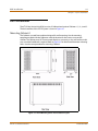
KSU Installation .......................................................................................................... 3-5
Mounting Cabinet 0 ......................................................................................................................... 3-5
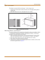
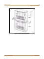
Mounting Cabinet 1 and Cabinet 2 ............................................................................................ 3-6
Connecting Sets of Cabinets ........................................................................................................ 3-9
KSU Grounding .................................................................................................................................. 3-10
Power Line Surge Protection ........................................................................................................ 3-11
Optional Mounting Rack ................................................................................................................ 3-12
Ring Generator Unit Installation ............................................................................... 3-13
Power Supply Unit Installation .................................................................................. 3-13
PCB Installation ........................................................................................................... 3-15
PCB Handling and General Installation ..................................................................................... 3-15
Main Processing Board Installation .......................................................................... 3-16
Program Module Unit ..................................................................................................................... 3-19
Modem Unit ........................................................................................................................................ 3-19
Link Module Unit ............................................................................................................................... 3-20
Miscellaneous Interface Unit Installation ................................................................. 3-22
Serial Interface Unit .......................................................................................................................... 3-24
XTS-IP - Installation Manual
December 2005
ii
Contents
CO/PBX Connections .................................................................................................. 3-25
Analog CO/PBX Line Interface Boards ....................................................................................... 3-25
DID Interface Board .......................................................................................................................... 3-28
Digital CO/PBX Line Interface Boards ........................................................................................ 3-29
ISDN and T1 Clocking ...................................................................................................................... 3-43
Station Connections ................................................................................................... 3-51
Electronic Telephone Interface Board ....................................................................................... 3-51
Single Line Interface Board ........................................................................................................... 3-54
Digital Telephone Interface Board ............................................................................................. 3-58
Flash-Based Voice Mail System .................................................................................. 3-61
Hard Drive-Based Voice Mail System ........................................................................ 3-62
System Wiring ............................................................................................................. 3-63
Battery Backup Wiring Installation ............................................................................................. 3-63
RS-232C Wiring on MPB and SIU ................................................................................................. 3-64
MISB Wiring ......................................................................................................................................... 3-65
Station Wiring .................................................................................................................................... 3-66
Wall Mounting the Digital Key Telephone ................................................................ 3-72
Wall Mounting the Electronic Key Telephone .......................................................... 3-73
Headset Installation ................................................................................................... 3-74
Caller ID Interface Unit Installation ........................................................................... 3-74
Selecting the Cable .......................................................................................................................... 3-74
IP Phones and Related Items ...................................................................................... 3-76
IP Keyset Power ................................................................................................................................. 3-77
Nomad Remote Services Gateway Module ............................................................................. 3-78
IP Module - AC/DC Adapter .......................................................................................................... 3-85
Door Box ...................................................................................................................... 3-86
4
Maintenance and Troubleshooting
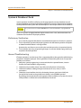
System & Database Check .......................................................................................... 4-3
Preliminary Verification .................................................................................................................. 4-3
General Troubleshooting ............................................................................................................... 4-3
Telephone Troubleshooting ...................................................................................... 4-4
Keyset Self Test .................................................................................................................................. 4-4
Keyset LCD/LED Test ........................................................................................................................ 4-4
Keyset Button Test ............................................................................................................................ 4-5
DSS LED/Button Test ....................................................................................................................... 4-5
Peripheral Cards and Components ........................................................................... 4-6
Key Telephones ................................................................................................................................. 4-6
Single Line Telephones ................................................................................................................... 4-7
DSS/BLF Console ............................................................................................................................... 4-7
CO Line Card Functions .................................................................................................................. 4-8
System Functions ............................................................................................................................. 4-9
Miscellaneous Functions ................................................................................................................ 4-11
Station Card Functions ................................................................................................................... 4-11
Maintenance Access ................................................................................................... 4-12
XTS-IP - Installation Manual
December 2005
Contents
iii
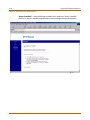
Maintenance ....................................................................................................................................... 4-12
Monitor ................................................................................................................................................. 4-21
Flash ROM Software Update ...................................................................................... 4-26
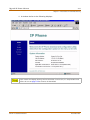
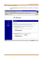
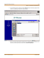
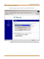
Upgrade IP Phone Software ....................................................................................... 4-30
Nomad RSGM Software Upgrade .............................................................................. 4-40
Changing WAN IP Address (via RS-232C Interface) .............................................................. 4-40
Upgrade Software Directly (via WAN interface) .................................................................... 4-44
VoIP Maintenance and Troubleshooting .................................................................. 4-50
VoIP Administrative Functions .................................................................................................... 4-50
Frequently Asked Questions ......................................................................................................... 4-59
VoIP Troubleshooting Guide ........................................................................................................ 4-60
VoIP24 Upgrade Procedure .......................................................................................................... 4-61
XTS-IP - Installation Manual
December 2005
iv
XTS-IP - Installation Manual
Contents
December 2005
Figures
v
Figures
KSU Structure .......................................................................................................................................................
XTS-IP Default Card Layout for Cabinet 0 ..................................................................................................
XTS-IP Mounting Holes and Installation Layout ......................................................................................
Mounting XTS-IP Cabinet .................................................................................................................................
Connecting Cabinet 0 and Cabinet 1 ..........................................................................................................
Mounting Cabinets 0, 1, & 2 ............................................................................................................................
Connecting Sets of Cabinets ...........................................................................................................................
Earth Cable between KSU and External RGU ............................................................................................
Optional Rack .......................................................................................................................................................
PSU Installation ....................................................................................................................................................
PCB Installation ....................................................................................................................................................
MPB1/2, PMU, and MODU Configuration ..................................................................................................
MPBE, PMU, and MODU Configuration .......................................................................................................
LMU1 Board Configuration .............................................................................................................................
LMU2 Board Configuration .............................................................................................................................
LMUE .......................................................................................................................................................................
MISB & SIU Installation ......................................................................................................................................
Talk Battery ............................................................................................................................................................
LCOBC with DTRU4 Installation .....................................................................................................................
DIDB w/DTRU Installation ................................................................................................................................
T1IB w/DTRU4 Module Installation ...............................................................................................................
PRIB w/DTRU4 Module Installation ..............................................................................................................
BRIB (Basic Rate Interface Board) ...................................................................................................................
VoIP Card with One VoIP Module Installed ...............................................................................................
VoIP Card - No VoIP Modules Installed ........................................................................................................
Connection Side of VoIP Module (Close-up) .............................................................................................
VoIP24 Card and Daughterboard ..................................................................................................................
Case 1 of Clock Chain ........................................................................................................................................
Case 2 of Clock Chain ........................................................................................................................................
Case 3 of Clock Chain ........................................................................................................................................
Case 4 of Clock Chain ........................................................................................................................................
Electronic Telephone Interface Board (ETIB) .............................................................................................
SLIBE & SLIBC w/MSGU and DTRU4 Module (SLIBE only) Installation ..............................................
Digital Telephone Interface Board (DTIB) ..................................................................................................
Flash-Based Voice Mail Card ...........................................................................................................................
Hard Drive-Based Voice Mail Card ................................................................................................................
Battery Back-Up Wiring .....................................................................................................................................
RS-232 9-Pin Connector Cable Wiring .........................................................................................................
External Paging Wiring .....................................................................................................................................
Loud Bell Wiring ..................................................................................................................................................
External Switch / Alarm Wiring ......................................................................................................................
Digital Station Jack Wiring ...............................................................................................................................
XTS-IP - Installation Manual
1-4
1-4
3-5
3-6
3-7
3-8
3-9
3-10
3-12
3-14
3-15
3-17
3-18
3-20
3-20
3-21
3-24
3-25
3-26
3-29
3-34
3-36
3-37
3-38
3-39
3-39
3-41
3-47
3-48
3-49
3-50
3-53
3-57
3-60
3-61
3-62
3-63
3-64
3-65
3-65
3-66
3-66
December 2005
vi
Figures
SLA (Single Line Adapter) ................................................................................................................................
Electronic Station Wiring .................................................................................................................................
Single Line Telephone Wiring ........................................................................................................................
PFTU Wiring Example (Circuit 1) ....................................................................................................................
Electronic Key Telephone Wall Mounting ..................................................................................................
1480 Caller ID Cable Connections .................................................................................................................
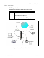
Caller ID System Configuration ......................................................................................................................
AC/DC Adapter for Keyset ...............................................................................................................................
Nomad RSGM Front & Rear Panels ...............................................................................................................
Remote configuration with Nomad RSGM ................................................................................................
AC/DC Adapter for IP Module ........................................................................................................................
Door Box ................................................................................................................................................................
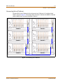
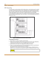
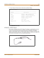
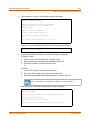
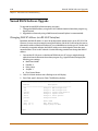
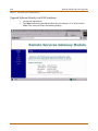
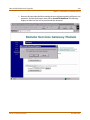
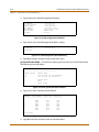
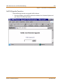
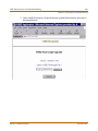
Remote Maintenance - Help Menu ..............................................................................................................
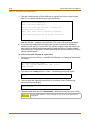
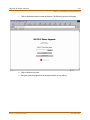
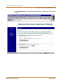
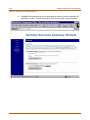
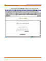
Remote Maintenance - System Configuration .........................................................................................
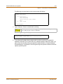
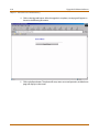
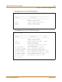
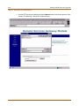
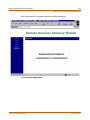
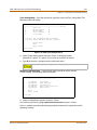
Remote Maintenance - CO/Station Configuration .................................................................................
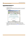
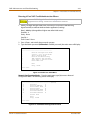
Example of T1IB in Cabinet 0, Slot 2 .............................................................................................................
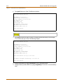
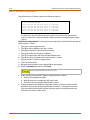
Example of VoIP24 Card in Cabinet 0, Slot 2 .............................................................................................
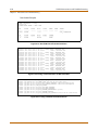
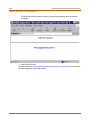
Remote Monitor - Help Menu .........................................................................................................................
Remote Monitor - Trace Mode Status ..........................................................................................................
Event Trace ............................................................................................................................................................
Event Trace in a Networking System ...........................................................................................................
VoIP Card Location Printout ............................................................................................................................
VoIP In/Out of Service Printout ......................................................................................................................
VoIP Trace - Main Menu ....................................................................................................................................
VoIP Network Configuration Printout .........................................................................................................
VoIP Configuration (Read All) .........................................................................................................................
VoIP Configuration (Read IP Address) .........................................................................................................
VoIP System/Call Status Printout ..................................................................................................................
VoIP (Call Status for All Channels) .................................................................................................................
VoIP Trace Setting Printout .............................................................................................................................
Actual CO Line Call via KSU Serial Port ........................................................................................................
Tracing a VoIP Card Status via KSU Serial Port .........................................................................................
Tracing a VoIP Call via VoIP Serial Port ........................................................................................................
VoIP24 Trace - Main Menu ...............................................................................................................................
3-68
3-69
3-69
3-70
3-73
3-75
3-75
3-77
3-79
3-80
3-85
3-86
4-13
4-14
4-15
4-16
4-17
4-22
4-23
4-25
4-25
4-50
4-50
4-51
4-51
4-52
4-52
4-52
4-52
4-53
4-56
4-56
4-56
4-65
XTS-IP - Installation Manual
December 2005
Tables
vii
Tables
Extension Boards .................................................................................................................................................
CO Interface Boards ...........................................................................................................................................
Add-on Boards .....................................................................................................................................................
System Capacity ..................................................................................................................................................
System Card Description ..................................................................................................................................
System Capacity ..................................................................................................................................................
Environment Specification ..............................................................................................................................
Loop Limits ............................................................................................................................................................
FCC Registration Numbers ..............................................................................................................................
Electrical Specifications ....................................................................................................................................
Dialing Specifications ........................................................................................................................................
Trunk Ordering Info: Public Network/Private Lease Lines ...................................................................
Dimension and Weight .....................................................................................................................................
Electronic Telephone Audible Signals .........................................................................................................
Single Line Audible Signals .............................................................................................................................
Digital Station Visual Signals - CO Line Buttons ......................................................................................
Digital Station Visual Signals - DSS/BLF Buttons .....................................................................................
Digital Station Visual Signals - Feature/Function Buttons ...................................................................
Signals to Called Station (Digital Station) ..................................................................................................
Signals to Calling Station (Digital Station) .................................................................................................
Voice Mail Confidence Tones .........................................................................................................................
Fuse Rating of the PSU ......................................................................................................................................
Dip Switch Settings (SW3) ...............................................................................................................................
MISB Connector Functions ..............................................................................................................................
MISB Wiring ...........................................................................................................................................................
T-1 Board LEDs .....................................................................................................................................................
T-1 Ordering Information .................................................................................................................................
T-1 Switch Positions ...........................................................................................................................................
Call Routing Criteria ...........................................................................................................................................
Call Routing Display Format ...........................................................................................................................
T-1 Ordering Specifications .............................................................................................................................
Telco to T1IB Interconnect Diagram - Pin Connections ........................................................................
PRIB Ordering Information ..............................................................................................................................
Telco to PRIB Interconnect Diagram - Pin Connections ........................................................................
BRIB Ordering Information ..............................................................................................................................
Bandwidths ...........................................................................................................................................................
VoIP Card LED Indications ...............................................................................................................................
VoIP24 Card LED Indications ...........................................................................................................................
ETIB Wiring ............................................................................................................................................................
SLIBE & SLIBC Wiring ..........................................................................................................................................
DTIB Wiring ...........................................................................................................................................................
System BackUp Duration .................................................................................................................................
XTS-IP - Installation Manual
1-8
1-9
1-11
2-3
2-4
2-6
2-7
2-7
2-7
2-8
2-9
2-9
2-9
2-10
2-11
2-12
2-12
2-13
2-13
2-14
2-14
3-13
3-16
3-22
3-23
3-30
3-30
3-30
3-32
3-33
3-33
3-33
3-35
3-35
3-36
3-38
3-39
3-41
3-52
3-54
3-59
3-63
December 2005
viii
Tables
MPB & SIU Communication Ports .................................................................................................................
PFTU Block Wiring ..............................................................................................................................................
IP Keyset Models .................................................................................................................................................
Flash Rates .............................................................................................................................................................
Key Telephones ...................................................................................................................................................
Single Line Interface Board - SLIBE/SLIBC w/MSGU48 ..........................................................................
DSS/BLF Console .................................................................................................................................................
Loop Start CO Interface Board (LCOBC) ......................................................................................................
PRI/BRI ISDN and T1 ...........................................................................................................................................
Master Processor Board (MPB) .......................................................................................................................
Modem Unit (MODU) .........................................................................................................................................
Program Module Unit (PMU) ..........................................................................................................................
Power Supply Unit (PSU) ..................................................................................................................................
Miscellaneous Interface Board (MISB) .........................................................................................................
DTMF Receiver Unit (DTRU/DTRU4) .............................................................................................................
Ring Generator Unit (RGU) ..............................................................................................................................
Power Failure Transfer Unit (PFTU) ...............................................................................................................
Digital Key Telephone Interface Board (DTIB) ..........................................................................................
Event Trace Buffer Commands ......................................................................................................................
HDLC Messages ...................................................................................................................................................
H.323 Messages ...................................................................................................................................................
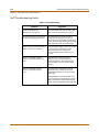
Troubleshooting .................................................................................................................................................
XTS-IP - Installation Manual
3-64
3-71
3-76
4-5
4-6
4-7
4-7
4-8
4-8
4-9
4-9
4-9
4-10
4-10
4-10
4-11
4-11
4-11
4-19
4-57
4-58
4-60
December 2005
1
Introduction
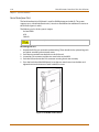
This manual provides the information necessary to operate and maintain the XTS-IP
System. The described features are based on the current software release. If any of
these features do not work on your system, call your sales representative.
This chapter describes and illustrates the components that may be used with the XTS-IP
System.
XTS-IP - Installation Manual
December 2005
»
»
»
»
»
»
»
N O T E S
»
»
»
»
»
»
»
Product Description
1-3
Chapter 1 - Introduction
Product Description
Introduction
The XTS-IP Digital Key Telephone System is a hybrid Key Telephone System, designed to meet
the telecommunication needs of medium or large sized business offices.
The XTS-IP System incorporates state of the art digital technology for command processing and
voice switching, utilizing a Pulse Code Modulation/Time Division Multiplexing (PCM/TDM, “A”
law or “U” law) distributed switching matrix.
The XTS-IP achieves a high level of flexibility by:
Employing a Universal Card Slot architecture in up to three Cabinets that house plug-in
Printed Circuit Boards.
Providing support for different types of instrumentation.
System Design
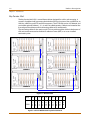
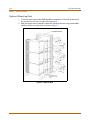
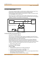
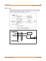
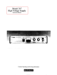
The Key Service Unit (KSU) of the XTS-IP is a wall-mounted cabinet that houses the MB (Mother
Board) and card slots for the CO line/Key Station/SLT/ISDN/VoIP interface boards, and other
useful boards.
In this system, the first unit is Cabinet 0. Second and third units (Cabinet 1 and Cabinet 2)can
be added above Cabinet 0 to increase capacity. A second set of up to three additional Cabinets
(Cabinets 3, 4, and 5) can be mounted next to the first set of Cabinets. The MPB should be
installed in the fixed MPB slot in Cabinet 0. To add Cabinets above Cabinet 0, the LMU1 should
be installed in the fixed LMU slot in Cabinet 0. LMU2 can be used in the fixed LMU slot of Cabinet
1 or Cabinet 2 and is connected with linked cable. To add a second set of Cabinets, an MPBE
must be used in Cabinet 0 and an LMUE must be used in the MPB slot of Cabinet 3. The MPBE
and LMUE are connected with a Link Cable. The same LMU1 and LMU2 arrangement is used to
connect Cabinets 3, 4, and 5 as is used to connect Cabinets 0, 1, and 2.
The system architecture is designed to allow a high level of software control over the system's
hardware. The software incorporates a vast array of features and capabilities including PC
Database Administration, Least Cost Routing, ACD, etc.
System Flexibility
The XTS-IP system supports numerous digital keysets and analog single line devices. With the
keysets, commonly used features are activated by direct button selection.
Many functions may be accessed by dialing specific codes or optionally by assigning these dial
codes to Flexible Buttons on the keyset. In addition to key telephones, an optional DSS/BLF
Console is available.
With the flexibility of the XTS-IP extensive feature content, and the capability to use an array of
instruments, the XTS-IP can be tailored to meet the short and long term needs of the most
demanding customer requirements.
XTS-IP - Installation Manual
December 2005
1-4
Product Description
Chapter 1 - Introduction
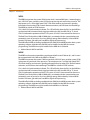
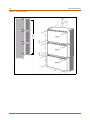
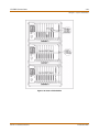
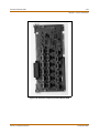
Key Service Unit
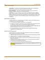
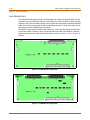
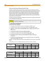
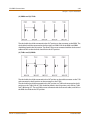
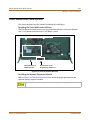
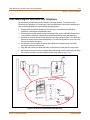
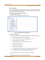
The Key Service Unit (KSU) is a metal frame cabinet designed for wall or rack mounting. It
contains a backplane with connectors that include a PSU slot, 9 universal slots, an MPB slot, an
LMU slot, a RAU slot, and PFTU and RGU connectors. The XTS-IP KSU consists of Cabinet 0, and
can include optional Cabinets 1, 2, 3, 4, and 5 for added capacity. Cable ties are located on the
front edge of the cabinet to allow connecting cables to be stored neatly.
LMU2
LMU2
The connecting cables for the stations and CO Lines exit through the outlet in the bottom of
KSU and can be connected to the Main Distribution Frame (MDF) or to a user installed
termination point.
CABINET 2
LMU2
LMU2
CABINET 5
CABINET 1
CABINET 0
LMU1
LMUE
LMU1
CABINET 4
CABINET 3
LINK CABLE
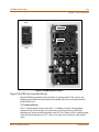
Figure 1-1: KSU Structure
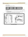
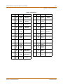
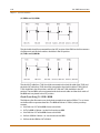
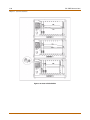
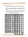
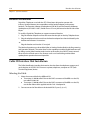
SLOT
CARD
0
1
2
3
4
5
6
7
8
9
D
T
2
4
D
T
2
4
D
T
2
4
S
L
1
2
N
O
N
E
L
C
O
8
L
C
O
8
L
C
O
8
N
O
N
E
M
P
B
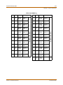
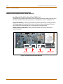
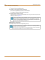
Figure 1-2: XTS-IP Default Card Layout for Cabinet 0
XTS-IP - Installation Manual
December 2005
Product Description
1-5
Chapter 1 - Introduction
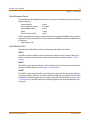
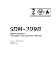
There are nine universal slots in the MB (slots 0-8). Peripheral cards can be installed in the
universal slots, but a card that contains a CPU cannot be installed in Slot 8 of Cabinet 0 (T1, PRIB,
BRIB, VOIP, LCOBC, SLIBC). There are fixed slots for the PSU, PFTU, MPB, LMU, RGU3, and RAU.
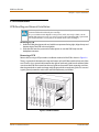
Power Supply Unit
A Power Supply Unit (PSU) is required in each Cabinet of the Key Service Unit. The PSU converts
commercial AC power (110 - 127 / 220 - 240V AC @ 50-60 Hz) to DC voltages, regulates the
voltages, and provides the appropriate DC voltages to the backplane for distribution to other
system components. Three DC outputs are provided: ±5V DC, +30V DC. LEDs in the PSU front
panel indicate valid outputs as well as the presence of AC input power.
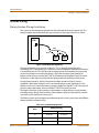
The PSU includes circuitry to charge externally connected 24-volt batteries and controls
operation of the battery back-up circuits. The PSU will provide system operating voltages from
the batteries if commercial AC power fails. The battery back-up control circuitry is incorporated
in the PSU to disconnect the batteries prior to a deep discharge or over-charge.
Ring Generator Unit
The Ring Generator Unit (RGU3) provides the ring voltage to the SLIB circuits to ring the SLT. The
RGU3 also provides the input to the Message Wait source on the SLIB cards. The output of the
RGU3 is 65V AC, 25 Hz. The RGU3 can support simultaneous ringing for 15 SLTs.
The RGU3 is fitted on the lower right side panel inside the Cabinet.
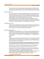
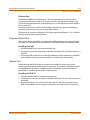
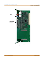
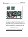
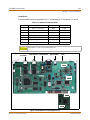
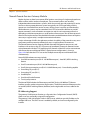
Main Processing Board
The Main Processing Board (MPB) controls and manages communication between peripheral
interface, supervises all resources in the system, controls gain adjustment of PCM signal,
generates system tone, and manages call processing of the system. The three MPBs available
for use with the XTS-IP are the MPB1, MPB2, and MPBE. MPB1 is used for a single-cabinet
installation only.
MPB1
The MPB1 incorporates the system's RAM, master clock, an RS-232C port, and the system's PCM
voice processing and main micro-processor. The microprocessor is a 32-bit high speed “RISC”
CPU which receives and transmits signaling information from/to other PCBs, controls feature
activation, and PCM time-slot interchange.
LD1 is the PLLU Synchronization Indicator. This LED will be lit when the PLLU on the MPB has
synchronized with an external clock signal provided to the KSU via a BRI, PRI, or T1 circuit.
LD2-LD9 indicate the operation of the XTS-IP system. LD10-LD13 are reserved for future use.
The MPB1 has the same features as the MPB2 described below, but does not include the
following: Paging Port, MOH Port, Port 5, Ethernet jack, or 4 built-in DTMF receivers.
The Real-Time Clock and the 2 MB of SRAM that is associated with the system database are
protected in cases of power loss by a long-life high-energy lithium battery. Onboard ROM
contains PCM tone, gain table, etc. needed for digital voice processing.
The 4 MB of flash ROM on the Program Module Unit (PMU) for the MPB1 contains basic system
operating software. A Modem Unit (MODU) can be installed on the MPB, for remote
programming. The MPB1 can only be installed in the MPB slot in Cabinet 0.
»
Add-on Boards: MODU and PMU
XTS-IP - Installation Manual
December 2005
1-6
Product Description
Chapter 1 - Introduction
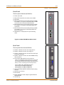
MPB2
The MPB2 incorporates the system's RAM, master clock, 1 external MOH port, 1 external paging
port, 2 RS-232C ports, and the system's PCM voice processing and main micro-processor. The
microprocessor is a 32-bit high speed “RISC” CPU which receives and transmits signaling
information from/to other PCBs, controls feature activation, and PCM time-slot interchange.
The MPB2 has 4 built-in DTMF receivers.
LD1 is the PLLU Synchronization Indicator. This LED will be lit when the PLLU on the MPB has
synchronized with an external clock signal provided to the KSU via a BRI, PRI, or T1 circuit.
LD2-LD9 indicate the operation of the XTS-IP system. LD10-LD13 are reserved for future use.
The Real-Time Clock and the 4 MB of SRAM that is associated with the system database are
protected in cases of power loss by a long-life high-energy lithium battery. Onboard ROM
contains PCM tone, gain table, etc. needed for digital voice processing.
The 8 MB of flash ROM on the Program Module Unit (PMU) for the MPB2 contains basic system
operating software. A Modem Unit (MODU) can be installed on the MPB, for remote
programming. The MPB2 can only be installed in the MPB slot in Cabinet 0.
»
Add-on Boards: MODU and PMU
MPBE
The MPBE must be used to expand the system beyond the first set of Cabinets 0, 1, and 2. It must
be connected with Link Cable to the LMUE in Cabinet 3.
The MPBE incorporates the system's RAM, master clock, 2 RS-232C ports, and the system's PCM
voice processing and main micro-processor. The microprocessor is a 32-bit high speed “RISC”
CPU which receives and transmits signaling information from/to other PCBs, controls feature
activation, and PCM time-slot interchange. The MPBE has 4 built-in DTMF receivers.
LD1 is the PLLU Synchronization Indicator. This LED will be lit when the PLLU on the MPB has
synchronized with an external clock signal provided to the KSU via a BRI, PRI, or T1 circuit.
LD2-LD9 indicate the operation of the XTS-IP system. LD10-LD13 are reserved for future use.
The Real-Time Clock and the 4 MB of SRAM that is associated with the system database are
protected in cases of power loss by a long-life high-energy lithium battery. Onboard ROM
contains PCM tone, gain table, etc. needed for digital voice processing.
The 8 MB of flash ROM on the Program Module Unit (PMU) for the MPB2 contains basic system
operating software. A Modem Unit (MODU) can be installed on the MPB, for remote
programming. The MPBE can only be installed in the MPB slot in Cabinet 0.
»
Add-on Boards: MODU and PMU
XTS-IP - Installation Manual
December 2005
Product Description
1-7
Chapter 1 - Introduction
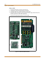
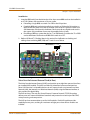
Miscellaneous Board
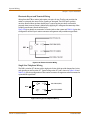
The Miscellaneous Board (MISB) incorporates the circuitry and interfaces for common optional
features including:
External Paging
2 ports
External Control Contacts
4 contacts
External BGM & MOH
2 ports
Alarm
1 input
RS-232C (optional SIU)
2 ports
An RJ21-type female connector is mounted on the front edge of the MISB for the connection
to the above circuits, except RS-232C serial interfaces. One MISB board can be installed in Slot 8
of Cabinet 0.
»
Add-on Board: SIU
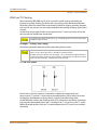
Link Module Unit
The Link Module Unit (LMU) provides a link between the Cabinets of the KSU.
LMU1
The LMU1 must be installed to connect Cabinet 0 to Cabinet 1 and to connect Cabinet 3 to
Cabinet 4. Signals are transmitted or received via linked cable as shown in Figure 1-1: KSU
Structure.
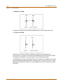
LMU2
The LMU2 is used to connect Cabinets 1 and 2 and Cabinets 4 and 5. Signals are transmitted or
received via linked cable as shown in Figure 1-1: KSU Structure.
LMUE
The LMUE is used to connect the first set of Cabinets 0, 1, and 2 with the second set of Cabinets;
it must be installed in Cabinet 3 (in the slot marked for MPB) and is connected with Link Cable
to the MPBE in Cabinet 0. Signals are transmitted or received via linked cable as shown in Figure
1-1: KSU Structure. The LMUE contains one external page port and one external background
music port.
XTS-IP - Installation Manual
December 2005
1-8
Product Description
Chapter 1 - Introduction
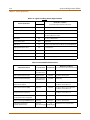
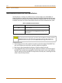
Extension Boards
Several types of extension boards are capable of supporting various types of telephones as
follows:
Table 1-1: Extension Boards
Board Name
Function
DTIB12
Provides 12 Digital Telephone interfaces
DTIB24
Provides 24 Digital Telephone interfaces
ETIB
Provides 12 Analog Telephone interfaces
SLIBC
Provides 12 Single Line Telephone interfaces with Caller ID
SLIBE
Provides 12 Single Line Telephone interfaces
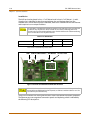
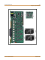
Digital Telephone Interface Board
The Digital Telephone Interface Board (DTIB) provides 2-wire interfaces for telephone
connection. Two versions are available (DTIB12 and DTIB24).
The DTIB provides digital voice and data communications to/from digital telephones.
An industry-standard amphenol-type female connector is mounted on the front edge of the
PCB for connection to the station interfaces. In addition, one LED is mounted on the PCB to
indicate the in use state of the connected telephones. It will turn on when one or more ports
are busy.
»
Add-on Boards: None
Electronic Telephone Interface Board
The Electronic Telephone Interface Board (ETIB) provides 2-wire interfaces for telephone
connection.
An industry-standard amphenol-type female connector is mounted on the front of the ETIB for
connection to the station interfaces.
»
Add-on Boards: None
Single Line Telephone Interface Board
The Single Line Telephone Interface Board (SLIB) provides 2-wire interfaces for telephone
connection. Two versions are available (SLIBE and SLIBC).
An industry-standard amphenol-type female connector is mounted on the front of the SLIBE
and SLIBC for connection to the station interfaces.
»
Add-on Boards: DTRU4 and MSGU48 on SLIBE, and MSGU48 on SLIBC.
XTS-IP - Installation Manual
December 2005
Product Description
1-9
Chapter 1 - Introduction
CO Interface Boards
The types of CO Interface boards are listed in the table and narrative that follow.
Table 1-2: CO Interface Boards
Board Name
Function
DIDB
Provides 4 Direct Inward Dial Lines
LCOBC
Provides 8 Loop Start CO Lines (Caller ID capable)
VOIP
Provides up to 8 VOIP interfaces over LAN
VOIP24
Provides up to 24 VOIP interfaces over LAN
T1IB
Provides 24 channels
PRIB
Provides 23 bearer channels and 1 data channel
BRIB
Provides 2 bearer channels and 1 data channel
Direct Inward Dial Board
The Direct Inward Dial Board (DIDB) provides four analog DID CO interface ports. The DIDB can
be optionally equipped with a DTMF Receiver Unit (DTRU) to detect DTMF tones. If a DIDB is
used, a DTRU is required; it does not necessarily have to be mounted on the DIDB, but it must
be installed within the system.
»
Add-on Boards: DTRU
Loop Start CO Line Interface Board
The Loop Start CO Line Interface Board (LCOBC) provides Loop Start CO Lines which support
pulse/DTMF signal. Each interface contains ring and loop current detection circuits, Analog-toDigital and Digital-to-Analog conversions, and pulse and ground flash signaling circuits. The
LCOBC contains LEDs to indicate the in use status of each CO Line.
The LCOBC is Caller ID capable and has an RJ21-type male connector.
The LCOBC can be equipped with a DTMF receiver unit (DTRU4) to detect DTMF tones.
»
Add-on Boards: DTRU4 and CIDU
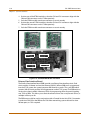
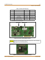
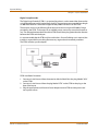
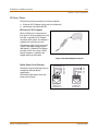
Voice Over the Internet Protocol Cards
The Voice Over the Internet Protocol (VoIP) card provides up to eight lines per card (two lines
per installed VOIP module). The VoIP24 card provides up to 24 line per card when a
daughterbaord is used. The VoIP/VoIP24 card allows bi-directional voice communication to
other devices via an IP network such as an internal Local Area Network (LAN), the Internet, or
a Wide Area Network (WAN) using the Ethernet Interface. It monitors for disconnect while using
minimal bandwidth. It also provides four-digit dialing and other features. The VoIP card uses up
to 8 fixed time slots and programming allows the use of up to 16 additional time slots that can
be used for either stations or CO lines.
»
Add-on Boards: VoIP modules
XTS-IP - Installation Manual
December 2005
1-10
Product Description
Chapter 1 - Introduction
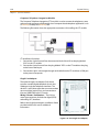
T1 Interface Board
The T-1 Interface Board (T1IB) provides the T-1 (1.544Mbps, 24-Voice Channel) digital interface
circuit, control circuitry, and synchronous clock control circuits. DTMF tone detection units can
be installed optionally on the T1IB. The T1IB has 8 LEDs on the front edge of the PCB which
indicates errors of T-1 line, in-use status, and synchronous clock enable status.
»
Add-on Boards: DTRU4
Primary Rate Interface Board
The Primary Rate Interface Board (PRIB) provides one Primary Rate Interface circuit. Each circuit
contains 23 bearer and one data channel (23B+D). When a PRIB card is programmed into the
system, the system interprets all B channels as trunks. Thus, one PRIB which contains 23B+D
circuits provides 23 line appearances to the system. The PRIB card uses 24 time slots when
installed.
The PRIB must usually be used in conjunction with a Channel Service Unit (CSU). Connection is
made via a DB15 from the PRIB to the CSU. When networking systems that are less than 50 feet
apart, no CSU is required.
The PRIB accepts two DTRU4 boards.
When ordering PRI lines from the telephone company, specify ESF framing and B8ZS line
coding. PRI only supports National ISDN 2 (NI-2). No other standards are supported.
»
Add-on Boards: DTRU4
Basic Rate Interface Board
The Basic Rate Interface Board (BRIB) interface provides four Basic Rate Interface circuits. Each
circuit is comprised of two bearer (64Kbps each) and one data (16Kbps) channels (2B+D). When
a BRIB is programmed into the system, the system interprets all B channels as trunks. Thus, one
BRIB which contains four 2B+D circuits provides eight line appearances to the system. A
maximum of seven BRIBs can be installed into the system (56 B channels).
The BRIB uses the U interface of the BRI standard. Connection to the network is made via RJ45
connectors on the front edge of the board. No CSU is required to connect to the central office.
The BRIB card uses eight time slots when installed.
When ordering BRI lines from the telephone company, specify Capability P as the ordering
code. National ISDN 1 (NI-1) is supported. No other standards are supported.
»
Add-on Boards: DTRU4
XTS-IP - Installation Manual
December 2005
Product Description
1-11
Chapter 1 - Introduction
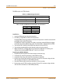
Add-On Boards
This section describes add-on boards, which can be installed on various types of boards to
support additional functions as shown in the following table.
Table 1-3: Add-on Boards
Board
Function
Position
CIDU
Caller ID Unit
LCOBC
DTRU
Two DTMF receiver circuits
DIDB
DTRU4
Four DTMF receiver circuits
LCOBC, SLIBE, T1IB,
PRIB, & BRIB
MSGU48
Provides message waiting light indication on SLTs SLIBE & SLIBC
PMU
Provides operating software
MPB
MODU
Provides a 19.2K baud modem for local access
MPB
RAU
Provides three relay contacts and two alarm
functions (not used)
RAU
SIU
Provides additional two RS232 serial interfaces.
MISB
Dual Tone Receiver Unit
The dual tone receiver unit (DTRU) provides Dual Tone Multi frequency (DTMF) circuits. The two
versions of the DTRU are: the DTRU and the DTRU4.
The DTRU can be installed on the DIDB to provide 2 DTMF circuits.
The DTRU4 can be installed on the LCOBC, SLIBE, T1IB, or PRIB to provide 4 DTMF circuits.
The resources above are shared across the entire system.
Message Waiting Unit
The message waiting unit (MSGU) provides a message waiting light indication on single line
telephones.
One or two MSGU48s can be installed on each SLIBE or SLIBC (required if message wait
indication is needed).
Program Module Unit
The CPU operates on code in the flash ROMs in the Program Module Unit (PMU) which contains
the system control, administration, and call processing. The PMU has 8 MB of ROM (4 MB in PMU
for MPB1).
»
The PMU must be installed on the MPB.
XTS-IP - Installation Manual
December 2005
1-12
Product Description
Chapter 1 - Introduction
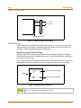
Modem Unit
The Modem Unit (MODU) (Modulator & Demodulator Unit) provides a communication method
interface for remote maintenance and remote PC Admin. It operates in full-duplex,
asynchronous modes at line rates up to 19.2 Kbps.
The Modem Unit provides an asynchronous modem for access to the system database and fault
reporting features from a remote site. The modem may be connected to a pre-selected CO Line
through the system-switching matrix. The MODU port is independent of the SIU standard
RS-232C port, allowing system database access, etc., without the need to interrupt the SMDR
output.
»
The optional MODU is installed on the MPB.
Relay Alarm Unit
The Relay Alarm Unit (RAU) provides three relay contacts and two alarm functions.
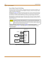
Serial Interface Unit
The Serial Interface Unit (SIU) provides an additional two RS-232C (ports 3 & 4) interface circuits
on the MISB. The SIU is useful for SMDR print out and Caller ID. The following is a list of the
system’s output:
On-line SMDR
Statistical information
Caller ID input
ACD
»
The optional SIU can be installed on the MISB.
XTS-IP - Installation Manual
December 2005
2
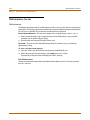
System Specifications
This chapter describes the hardware used by the XTS-IP system and lists the
specifications for each component.
XTS-IP - Installation Manual
December 2005
»
»
»
»
»
»
»
N O T E S
»
»
»
»
»
»
»
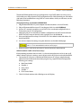
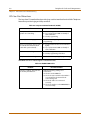
System Capacities
2-3
Chapter 2 - System Specifications
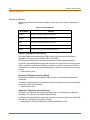
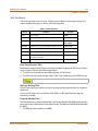
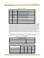
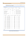
System Capacities
The following tables and charts describe system capacities and display the configuration
flexibility of the system.
The KSU contains a PSU slot, nine universal slots, one MPB slot, one LMU slot, one RAU slot, and
PFTU and RGU connectors.
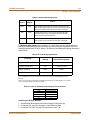
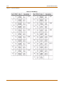
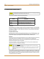
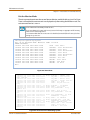
Table 2-1: System Capacity
Description
Univ
Slots
Usable Capacity
MPB2
MPBE
MPB1
Cabinet 0
9
136 Time Slots
136 Time Slots
136 Time Slots
Cabinet 1
9
96-144 Time Slots**
96-144 Time Slots**
N/A
Cabinet 2
9
96-144 Time Slots**
96-144 Time Slots**
N/A
Cabinet 3
9
144 Time Slots
N/A
N/A
Cabinet 4
9
96-144 Time Slots**
N/A
N/A
Cabinet 5
9
96-144 Time Slots**
N/A
N/A
KSU Cabinets
6 Cabinets
3 Cabinets
1 Cabinet
Serial Ports (RS-232C)
4 Ports
(MPB: 2, MISB: 2)
4 Ports
(MPB: 2, MISB: 2)
3 Ports
(MPB:1, MISB:2)
Alarm
3 Inputs
(RAU: 2, MISB: 1)
3 Inputs
(RAU: 2, MISB: 1)
3 Inputs
(RAU: 2, MISB: 1)
External Control
Contacts
7 Contacts
(RAU: 3, MISB: 4)
7 Contacts
(RAU: 3, MISB: 4)
7 Contacts
(RAU: 3, MISB: 4)
Music Source
Inputs
3 Inputs
(LMUE: 1, MISB: 2)
3 Inputs
(MPB: 1, MISB: 2)
2 Inputs
(MPB: 0, MISB: 2)
DTMF
Receivers
24 Receivers
24 Receivers
24 Receivers
(MPB: 4, SLT/CO cards: 20) (MPB: 4, SLT/CO cards: 20) (MPB: 0, SLT/CO cards: 24)
Power Fail
Circuits
30 Circuits
30 Circuits
30 Circuits
External
3 Zones
(LMUE: 1, MISB: 2)
3 Zones
(MPB: 1, MISB: 2)
2 Zones
(MPB: 0, MISB: 2)
Internal
8 Zones
8 Zones
8 Zones
DSS/BLF Consoles
3 Consoles (per station)
3 Consoles (per station)
3 Consoles (per station)
Ethernet
Connection
1
1
N/A
Time Slots*
Paging Zones
* Time slots are used to support each CO Line and each station. A Cabinet cannot support more than 96 stations.
** Maximum time slots on Cabinets 1 and 2 or in Cabinets 4 and 5 can range from 96 to 144 each, but the total time slots between each
two Cabinets cannot exceed 240.
*** MPB1 - Maximum COs are 48 and maximum stations are 96
MPB2 - Maximum COs are 144 and maximum stations are 252
MPBE - If maximum of 216 COs are used, then maximum stations are 384. If maximum stations of 492 are used (400 digital station
max, remaining 92 are SLT), then maximum COs are 108. Total usable time slots in the system is 600.
XTS-IP - Installation Manual
December 2005
2-4
System Components
Chapter 2 - System Specifications
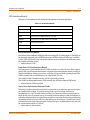
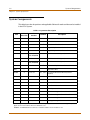
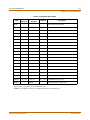
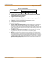
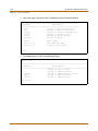
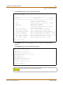
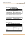
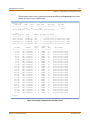
System Components
This table shows the slot positions and applicable Cabinets for each card that can be installed
in the XTS-IP System.
Table 2-2: System Card Description
Item
Number of
Time Slots
Slot
Position
Cabinets
0, 1, & 2
Description
BRIB
8
1-7 or 0-7
Basic Rate Interface Board
CIDU
--
LCOBC
DIDB
4
1-8 or 0-8
All
Direct Inward Dial Board
DTIB12
12
0-8
All
Digital Telephone Interface Board
DTIB24
24
0-8
All
Digital Telephone Interface Board
DTMFA
---
LCOBC, SLIBE,
T1IB, PRIB, BRIB
DTMF Receiver Unit (4 port)
DTRU
---
DIDB
DTMF Receiver Unit (2 port)
DTRU4
---
LCOBC, SLIBE,
T1IB, PRIB, BRIB
DTMF Receiver Unit (4 port)
ETIB
12
1-8 or 0-8
KSU
---
---
LCOBC
8
1-7 or 0-7
LMU1
---
LMU
LMU2
---
LMU
LMUE
---
LMU
3
Link Module Unit
MISB
---
8 only
0
Miscellaneous Board
MODU
---
MPB
19.2 Kbps Internal Modem
MPB1
---
MPB
Main Processing Board = 136 Time Slots Usable
MPB2
---
MPB
Main Processing Board = 376 Time Slots Usable
MPBE
---
MPB
Main Processing Board = 600 Time Slots Usable
MSGU48
---
SLIBE, SLIBC
Message Waiting Unit
Caller ID Unit
All
Electronic Telephone Interface Board
Key Service Unit
0, 1, 2, & 3 Loop Start CO Interface Board (Caller ID
capable)
0&3
Link Module Unit
1, 2, 4, & 5 Link Module Unit
The first range of slot positions, for entries that show two ranges, applies to Cabinets 0. The second range of slot positions
applies to slots in other cabinets where the card can be used.
EXAMPLE -- The BRIB card can be used in slot 1-7 of Cabinet 0 and in slots 0-7 in Cabinets 1 & 2.
XTS-IP - Installation Manual
December 2005
System Components
2-5
Chapter 2 - System Specifications
Table 2-2: System Card Description
Item
Number of
Time Slots
Slot
Position
Cabinets
Description
PFTU
---
---
Power Failure Transfer Unit
PMU
---
MPB1
Program Module Unit, 4 MB ROM
PMU
---
MPB2/MPBE
Program Module Unit, 8 MB ROM
PRIB
up to 24
PSU
---
PSU
RAU
---
RAU
RGU3
---
---
Ring Generator Unit (25Hz): Sine Wave, Internal
SIU
---
MISB
Serial Interface Unit
SLIBC
12
1-7 or 0-7
SLIBE
12
1-8 or 0-8
All
T1IB
up to 24
1-7 or 0-7
0, 1, & 2
VMIB
8
1-7 or 0-7
0, 1, 2, & 3 Voice Mail Interface Board - Flash-based
VMIB
12
1-7 or 0-7
0, 1, 2, & 3 Voice Mail Interface Board - Hard Drive-based
VOIP
up to 8
1-7 or 0-7
0, 1, 2, & 3 VoIP Card w/one VoIP Module
VOIP
up to 8
1-7 or 0-7
0, 1, 2, & 3 VoIP Card w/two VoIP Modules
VOIP
up to 8
1-7 or 0-7
0, 1, 2, & 3 VoIP Card w/three VoIP Modules
VOIP
up to 8
1-7 or 0-7
0, 1, 2, & 3 VoIP Card w/four VoIP Modules
Module
--
VOIP24
up to 24
Module
--
1-7 or 0-7
VOIP
1-7 or 0-7
VOIP24
0, 1, & 2
Primary Rate Interface Board
Power Supply Unit, 350W
0
Relay Alarm Unit
0, 1, 2, & 3 Single Line Interface Board w/ Caller ID
Single Line Interface Board
T1 Interface Board
VoIP module (only for upgrade)
0, 1, 2, & 3 VoIP24 Base Card (12 port)
Daughterboard for VoIP24 Card
The first range, for entries that show two ranges of slot positions, applies to Cabinet 0. The second range of slot positions
applies to slots in other cabinets where the card can be used.
EXAMPLE -- The T1IB can be used in slot 1-7 of Cabinet 0 and in slots 0-7 in Cabinets 1 & 2.
XTS-IP - Installation Manual
December 2005
2-6
System Configuration Tables
Chapter 2 - System Specifications
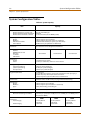
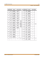
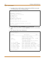
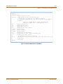
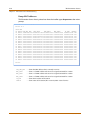
System Configuration Tables
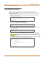
Table 2-3: System Capacity
Capacity
Item
Account Codes
Number of digits per account code
Number of Account Codes- Unverified
Number of Account Codes - Verified
Up to 12 unverified digits
Unlimited
500 Account Codes (750 for MPBE systems)
ACD Groups
Groups
Members
RAN Announcements
Calls in Queue
Software supports up to 32 Groups
Software supports up to 252 stations in each Group
32 RAN Announcements per system, 3 per ACD Group
All CO Lines may be queued for an ACD Group
Attendants
Up to 6 stations can be designated as Attendants.
CO Lines
CO/PBX/Centrex Lines
DID Lines
T-1 Trunks
ISDN Trunks
MPB1
MPB2
MPBE
48 maximum
144 maximum
216 maximum
Conference
Circuits
Parties
10 Conferences per system
8 parties per conference, of which 5 can be external
Dialing Memory
Station Speed Dialing
System Speed Dialing
Total Speed Dial
20 Bins per station (24-digits)
980 Bins per system (24-digits)
3000 Bins per system (24-digits)
Digital DSS/BLF Units
180 maximum
Each DSS/BLF unit requires 1 station port and reduces station capacity by 1.
DSS/BLF maps may not be duplicated at one station.
1 station may have up to 3 DSS/BLF units associated with it.
DISA Circuits
Unlimited number of CO lines may be programmed simultaneously.
Hunt Groups
Groups
Members
Types
Software supports up to 8 Groups
Software supports up to 24 stations in each Group
Station, Pilot Hunting, or Pilot Ring All
Loop Supervision Disconnect
700 msec. duration (CO or Internal call to SLT)
Music Channels
Music-On-Hold/Background Music
8 Channels per system (4-8 on CO, ports 1 & 2 on MISB, port 3 on MPB2) (port 3 is
unavailable for MPB1)
MPB1
Page Zones
Internal Paging
External Paging
XTS-IP - Installation Manual
20 max (software
controlled)
2 maximum
MPB2
20 max (software
controlled)
3 maximum
MPBE
20 max (software
controlled)
3 maximum
December 2005
System Configuration Tables
2-7
Chapter 2 - System Specifications
Table 2-3: System Capacity
Stations
Analog Stations
Digital Telephones
Single Line Telephones
MPB1
MPB2
MPBE
96 maximum
252 maximum
(No more than 96
stations are supported
per Cabinet.)
400 maximum
400 maximum
480 maximum
UCD Groups
Groups
Members
RAN Announcements
Calls In Queue
Software supports up to 8 Groups
Software supports up to 8 stations in each Group
32 RAN Announcements per system, 2 per UCD Group
All CO Lines may be queued for a UCD Group
Voice Mail Groups
Groups
Members (ports)
Integration Method
Positive Disconnect
VM Message Wait
VM Disconnect Signal
Software supports up to 8 Groups
Software supports up to 24 stations per group
In-Band signaling (DTMF)
Loop supervision is provided to ensure disconnect
Programmable 12-digit (DTMF) string
If 0 digits are programmed, 15 sec of silence are followed by a busy tone.
Table 2-4: Environment Specification
Item
Degrees (ºF)
Degrees (ºC)
Operation Temperature
32-104
0-40
Optimum Operation Temperature
68-78
20-26
Storage Temperature
32-158
10-70
Relative Humidity
0-80% non-condensing
Table 2-5: Loop Limits
Item
Capacity
Analog Electronic Telephone*
Maximum length of station loop:
1000 feet of 24 AWG
(4 wire, inside wiring, twisted cable)
Digital Telephones*
Maximum length of station loop:
1000 feet of 24 AWG
(2-wire, inside wiring, twisted cable)
Single Line Telephones*
2000 feet of 24 AWG
*All stations must be installed in the same building. Station circuitry does not contain protection to support offpremise operation.
Table 2-6: FCC Registration Numbers
System
FCC Number
For a Key System configuration (button appearance)
KF: 5JYKOR-45504-KF-E
For a Hybrid System configuration (dial access codes)
MF: 5JYKOR-45505-MF-E
XTS-IP - Installation Manual
December 2005
2-8
System Configuration Tables
Chapter 2 - System Specifications
Table 2-7: Electrical Specifications
Item
Specification
Power Supply
AC Voltage Input
AC Power
AC Input Fuse
DC Output Voltage
120 or 220 +/- 10% Volt AC @48-63Hz
350W
5.0 amp @ 220Volt AC
+ 5V @ 10A, - 5V @ 1.5A, + 30V @ 8.4A
Battery Backup
Input Voltage
Battery Fuse
Charging Current
24Volt DC
12.5amp @250Volt AC
Maximum 1A
External Relay Contact
1 amp @24Volt DC
Longitudinal Balance
60 db from 200 Hz to 1,000 Hz
40 db from 1000 Hz to 4000 Hz
Idle Channel Noise
Less than 15 dbrnco for all connections
Cross Talk Attenuation
Greater than 75 dbm Station to CO and Station to Station
Single Frequency Distortion
(300 - 3400 Hz)
Station to CO Line and station to station:
Better than 2.0% or 34 db for an
Output level -30 dbm to 0 dbm
Ringing Detect Sensitivity
40Vrms @16-30Hz
30Vrms @30-37Hz
Ringer Equivalence Number (REN)
LCOB: 0.8B; DIDB: 0.0B; T1IB: 6.0P
Co Line Signaling - DTMF
Frequency pair at ±5dbm
Frequency tolerance ±1.5%
CO Line Signaling - Dial Pulse
10 pps and 20 pps programmable
Input Level Range
+10 db maximum
Music Source
Music-On-Hold input
Background Music input
600Ω input at Ødbm maximum from music source
600Ω input at Ødbm maximum from music source
External Page Port
Output Impedance
Output Power w/o Compression
600Ω @ 0dbm
5 milliwatt max
CSA File Number
(NRTL/C) LR57228
Telephone Transmitter
Electret mic compatible
XTS-IP - Installation Manual
December 2005
System Configuration Tables
2-9
Chapter 2 - System Specifications
Table 2-8: Dialing Specifications
Item
Specification
DTMF Dialing
Frequency Deviation
Rise Time
Duration of DTMF Signal
Interdigit Time
Less than +/-1%
Maximum 3ms
Minimum 75ms
Minimum 75ms
Pulse Dialing
Pulse Dialing Rate
Pulse Break/Make Duration
10 or 20 pps
60/40% or 67/33%
CO Type
Loop Start, 600 ohm, current sensing
Table 2-9: Trunk Ordering Info: Public Network/Private Lease Lines
System Port Identification, Facility Interface and Service Order Codes
Ringer Equivalent
Number (REN)
Facility Line
Interface
Jack Type
CO Port (LCOBC)
0.8B
02LS2
RJ21X
Direct Inward Dial
(DIDB)
0.0B
02RV2-T
RJ11
T-1 Port (T1IB) or
ISDN Port (PRIB)
6.0P
04DU9-B
RJ45
Interface Card
Ordering
Specification
T1 circuit used with
PRI networking
B8ZS, non-channelized, pointto-point T1, 1.544 Mbps
Table 2-10: Dimension and Weight
Height
Width
Depth
Weight
Item
in
mm
in
mm
in
mm
lbs
kg
KSU
16.2
411
24.8
630
9.4
238
25.3
11.5
Digital Keyset
9.3
236
7.6
192
3.3
84
3.3
1.5
Digital DSS/BLF Console
9.3
236
4.9
125
2.4
62
2.0
0.9
XTS-IP - Installation Manual
December 2005
2-10
System Configuration Tables
Chapter 2 - System Specifications
Table 2-11: Electronic Telephone Audible Signals
Type of Signal
Frequency
Signal Duration
(in seconds unless otherwise indicated)
Electronic Telephone Signals
Incoming CO Line
440+480
0.4 on/0.4 off/0.4 on/2.0 off; Repeated
Intercom Tone Ringing
440+480
0.8 on/2.4 off; Repeated
440
0.2 on/0.2 off; (3 bursts)
Transferred CO Line
440+480
0.8 on/2.4 off; Repeated
CO Line Recall
440+480
0.24 on/0.6 off; Repeated
Message Wait Call Back
440+480
0.8 on/2.4 off; Repeated
CO Queue Call Back
440+480
0.8 on/2.4 off; Repeated
Intercom Call Announce (H-P modes)
Camp-On
440
0.8 on (1 burst)
Paging Alert Tone
440
1.0 on
Type of Signal
Frequency
Signal Duration
(in seconds unless otherwise indicated)
Electronic Telephone Confidence Tones
Intercom Ringback
440+480
0.8 on/2.4 off
Transferred CO Line
440+480
0.8 on/2.4 off
Call Announce
440
0.2 on/0.2 off; (3 bursts)
Busy Tone
480+620
1.0 on/0.2 off/1.0 on/0.2 off/0.2 on/ 0.2 off/
0.2on/0.2 off/0.2 on; Repeated
Error Tone
480+620
0.2 on/0.1 off; Repeated
Intercom Dial Tone
350+440
Steady
DND Tone
350+440
0.4 on/0.4 off/0.2 on/0.2 off/0.2 on; Repeated
Paging Confirmation Tone
350+440
1.0 on
Conference Time-out/Re-Enter Tone
Confirmation Tone
XTS-IP - Installation Manual
440
350+440
Programmable Steady Tone
0.2 on/0.2 off; (3 bursts) CO/PBX
December 2005
System Configuration Tables
2-11
Chapter 2 - System Specifications
Table 2-12: Single Line Audible Signals
Type of Signal
Signal Duration
(in seconds unless otherwise indicated)
Frequency
Single Line Signals
Incoming CO Line
20Hz 90 VAC
2.0 on/4.0 off; Repeated
Intercom Tone Ringing
20Hz 90 VAC
1.0 on/0.2 off/1.0 on/4.0 off; Repeated
Transferred CO Line
20Hz 90 VAC
1.0 on/0.2 off/1.0 on/4.0 off; Repeated
CO Line Recall
20Hz 90 VAC
2.0 on/4.0 off; Repeated
CO Queue Call Back
20Hz 90 VAC
1.0 on/2.0 off; Repeated
Type of Signal
Signal Duration
(in seconds unless otherwise indicated)
Frequency
Single Line Confidence Tones
Intercom Ringback
440+480
1.0 on/3.0 off
Transferred CO Line
440+480
1.0 on/0.2 off/1.0 on/4.0 off
Call Announce
440
0.2 on/0.2 off; (3 bursts)
Busy Tone
480+620
1.0 on/0.2 off/1.0 on/0.2 off/0.2 on/ 0.2 off/0.2on/
0.2 off/0.2 on; Repeated
Error Tone
480+620
0.2 on/0.1 off; Repeated
Intercom Dial Tone
350+440
Steady
DND Tone
350+440
0.2 on/0.2 off/0.2 on/0.2 off/0.2 on/0.2 off; burst
Paging Confirmation Tone
350+440
1.0 on
Conference Time-out Tone
440
Confirmation Tone
XTS-IP - Installation Manual
350+440
Programmable Steady Tone
0.2 on/0.2 off; (3 bursts)
December 2005
2-12
System Configuration Tables
Chapter 2 - System Specifications
Table 2-13: Digital Station Visual Signals - CO Line Buttons
Feature/Function
Flash Rate
LED Color
60 ipm double wink
Red
Transferred CO Ringing
120 ipm Flash
Red
CO Line Recalling
480 ipm Flutter
Red
60 ipm double wink
Red
120 ipm Flash
Green
60 ipm wink
Green
480 ipm Flutter
Red
ON Steady
Red
Idle
OFF
ON Steady
Red
Incoming CO Ringing
System HOLD
Exclusive HOLD (I-Hold)
I-HOLD (System)
CO Line Queue Call Back
CO Line in Use
CO Line
Exclusive Hold (other stations)
Table 2-14: Digital Station Visual Signals - DSS/BLF Buttons
Feature/Function
Flash Rate
LED Color
ON Steady
Red
120 ipm Flutter
Red
Steady
Red
Message Waiting Call Back
120 ipm Flutter
Red
Station in Do Not Disturb
60 ipm Double Flash
Red
Camp On (by station)
120 ipm Flash
Red
Automatic Call Back
120 ipm Flash
Red
Station Unavailable (ACD/UCD)
60 ipm Flash
Red off (3 bursts)+480
Off-Hook (Busy)
Incoming Intercom Ring
Call Announce (H or P Mode)
XTS-IP - Installation Manual
December 2005
System Configuration Tables
2-13
Chapter 2 - System Specifications
Table 2-15: Digital Station Visual Signals - Feature/Function Buttons
Feature/Function
Flash Rate
LED Color
Call Forward (active)
Steady
Red
Message Wait (active)
Steady
Red
Camp On (active)
120 ipm Flash
Red
Call Back (active-initiator)
120 ipm Flash
Red
480 Flutter
Red
DND (active)
Steady
Red
Mute
Steady
Red
On/OFF
Steady
Red
Conference
Steady
Red
Speed (moment on until bin address dialed)
Steady
Red
Personalized Messages
15 ipm Flash
Red
Tone Intercom Call (Hold button)
15 ipm Flash
Red
Loop
same as CO
Green/Red
Pool
same as CO
Green/Red
Transfer
60 ipm Flash
Green
CO Line Queue (active)
Table 2-16: Signals to Called Station (Digital Station)
Feature (Indication)
Sound in Hz
Occurrence - Cadence
(in seconds unless otherwise indicated)
Incoming CO Line
(*user selectable)
0.4 on/0.4 off/0.4 on/2.0 off
Intercom Tone Ringing
(*user selectable)
0.8 on/2.4 off; Repeated
935
0.2 on/0.2 off; (2 bursts)
Transferred CO Line
(*user selectable)
0.2 on/0.2 off; (2 bursts)
CO Line Recall
(*user selectable)
0.2 on/0.6 off; Repeated
Message Waiting Call Back
(*user selectable)
0.8 on/2.4 off; Repeated
Queued CO Line Call Back
(*user selectable)
0.2 on/0.6 off; Repeated
Intercom Call Announce (H & P)
Camp On
935
0.8 second burst
Alarm Tone - Repeated
701/857
1.0 on/.25 off; Repeated
Alarm Tone - Single (Continuous)
701/857
1.0 on; (once every 30-60 seconds until alarm is reset)
* Only one (1) tone can be selected by a station at a time. This tone is used for all signaling that uses the “User
Selectable” tone.
XTS-IP - Installation Manual
December 2005
2-14
System Configuration Tables
Chapter 2 - System Specifications
Table 2-17: Signals to Calling Station (Digital Station)
Sound in Hz
Occurrence - Cadence
(in seconds unless otherwise indicated)
Feature (Indication)
Station
Intercom Ring Back Tone
1215/1471
1.0 on/2.8 off; Repeated
Intercom Call Announce
935
0.2 on/.24 off; three (3) times (HF mode)
Busy Tone
701
1.0 on/0.2 off/ 1.0 on/0.2 off/0.6 on/0.6 off/0.2 on/0.2off/
0.2 on/0.2 off/0.2 on/0.2 off
Error Tone
701
0.2 on/0.1 off; Repeated
Intercom Dial Tone
420
Continuous
DND Tone
701
0.26 on/0.2 sec off/0.2 on/0.2 off/0.2 on/0.6 off; Repeated
Paging Confirmation Tone
935
1 second burst
Conference Time Out Warning Tone
420
1 second burst
Programming Confirmation Tone
440
three 100ms bursts
Programmed Error Tone
1471
0.2 on/0.2 off; Six (6) times
Table 2-18: Voice Mail Confidence Tones
VM Condition Action
Tone Received
Sound In Hz
Occurrence - Cadence
(in seconds unless otherwise indicated)
Off Hook
Internal Dial Tone
(no stutter tone)
350/440
Continuous
Calls an Internal Station (idle)
Ring Back Tone
440/480
0.8 on/2.4 off; Repeated
Initiate a Transfer (hook-flash)
Internal Dial Tone
(no stutter tone)
350/440
Continuous
Calls an Internal Station (busy)
*Call back not allowed
Busy Tone
480/620
1.0 on/0.2 off/1.0 on/0.2 off/0.2 on/
0.2 off/0.2 on/0.2 off/0.2 on
Calls an Internal Station (DND)
Busy Tone
480/620
1.0 on/0.2 off/1.0 on/0.2 off/0.2 on/
0.2 off/0.2 on/0.2 off/0.2 on
Calls an Internal Station
(programmed/not equipped)
Busy Tone
480/620
1.0 on/0.2 off/1.0 on/0.2 off/0.2 on/
0.2 off/0.2 on/0.2 off/0.2 on
Calls an Internal Station
(not programmed/not equipped)
Error Tone
480/620
0.2 on/0.1 off; Repeated
Dials an Invalid Digit/FACODE/Station
Error Tone
480/620
0.2 on/0.1 off; Repeated
Calling Party Disconnects
(Internal or External call)
Silence or
0 or
(Continuous or as programmed)
(Disconnect Digits) (DTMF Digits)
XTS-IP - Installation Manual
December 2005
System Configuration Tables
2-15
Chapter 2 - System Specifications
VoIP24 Station Port Capacity
A maximum of 48 IP stations can be accommodated on the MPB1 system.
A maximum of 96 IP stations can be accommodated on the MPB2/MPBE systems.
Cabinets 0, 1, and 2 can be used in MPB2/MPBE systems. Cabinet 3 can also be used in
MPBE systems.
A maximum of 3 VoIP24 cards can be installed per cabinet.
A maximum of 3 VoIP24 cards can be installed per MPB1 system.
A maximum of 9 VoIP24 cards can be installed per MPB2/MPBE system.
The VoIP24 base card (12 ports) can accommodate 24 IP stations in a blocking
arrangement.
The VoIP24 card with Daughterboard can accommodate 24 IP stations (non-blocking).
Cannot accommodate a 2 to 1 ratio.
Blocking = A user goes off-hook and may not receive dialtone if no IP resources are available
(busy).
Non-blocking = A user has a dedicated IP channel at all times. No busy condition.
Blocking
MPB1
MPB2
MPBE
Cards
Stations
Cards
Stations
Cards
Stations
VoIP24 base card
2
48
4
96
4
96
VoIP24 w/daughterboard*
--
--
--
--
--
--
* Blocking is not applicable to VoIP24 w/daughterboard
Non-Blocking
MPB1
MPB2
MPBE
Cards
Stations
Cards
Stations
Cards
Stations
VoIP24 base card
2
24
6
72
6
72
VoIP24 w/daughterboard
2
48
4
96
4
96
XTS-IP - Installation Manual
December 2005
2-16
System Configuration Tables
Chapter 2 - System Specifications
XTS-IP - Installation Manual
December 2005
3
System Installation
This chapter provides the basic system installation and wiring instructions for the
XTS-IP, as well as how to install the optional cards and interface units.
XTS-IP - Installation Manual
December 2005
»
»
»
»
»
»
»
N O T E S
»
»
»
»
»
»
»
Introduction
3-3
Chapter 3 - System Installation
Introduction
As with any sophisticated communications device, installation of the XTS-IP requires the care
and forethought of a competent technician. To assure easy servicing and reliable operation,
several factors must be considered when planning the system installation. The installation
consists of these major steps:
Site Preparation
KSU and Power Supply (PS) Installation
PCB Installation
System Wiring
Keyset and Terminal Installation
System Programming and Verification
Installing the XTS-IP is quick and efficient if these installation instructions are followed.
Site Preparation
General Site Considerations
The first step is to locate an acceptable site for the common equipment (KSU, boards, etc.).
When locating a mounting site for the KSU, the following points must be considered.
Wall Mounting -- The KSU is designed for wall mounting and should not be mounted
directly to a masonry or plasterboard wall. It is recommended that a 1/2 inch plywood back
board be firmly mounted to the wall, and the KSU and main distribution frame be mounted
to the back board.
Rack Mounting -- The KSU is also designed for rack mounting using the optional floor or
cabinet-model rack. If using the rack mounting option, ensure the location for the unit is on a
flat flooring area.
Dedicated Access -- The location must have access to a dedicated 120 Volt AC (±10%), 60 Hz,
single-phase circuit with a circuit breaker or fuse rated at 15 amps. A 3-wire (parallel blade
grounded outlet should be within approximately 6 feet of the lower left rear of the Cabinet 0
mounting.
Grounding -- The location must have access to a good earth ground, such as a metallic cold
water pipe with no non-metallic joints. The ground source should be located as close as
possible to the system.
Ventilation -- The system should be located in an area which is well ventilated with a
recommended temperature range of 68°-78° F and a relative humidity range of 5-60%
(non-condensing).
Distance Parameters -- The system should be located within 25 feet of the telephone
company’s termination point. Also, the location should be within the prescribed station loop
lengths for all keysets and terminals. If existing cabling is to be used, the location of existing
cabling and conduits should be considered.
XTS-IP - Installation Manual
December 2005
3-4
Site Preparation
Chapter 3 - System Installation
Accessibility -- The location should have adequate accessibility, space, and lighting for
future servicing and should consider the need for future expansion.
Hazard Protection -- The system should be located in an area that is protected from
flooding, flammable materials, excessive dust and vibration.
Interference -- The site should be away from radio transmitting equipment, arc-welding
devices, copying machines and other electrical equipment that are capable of generating
electrical interferences. Operation of this equipment may cause interference; in this case the
user, at their own expense, must take whatever measures may be required to correct the
interference.
Backboard Installation
A wooden backboard is recommended for all installations and must be installed when the
location has masonry or plasterboard walls.
A 1/2-inch plywood material is sufficient for most installations.
The back-board should be mounted at a convenient height, about 3 feet above the floor
and bolted in a number of places to distribute the weight of the system.
Space should be available on the bottom side of the back-board for the MDF cabling and
for optional equipment such as a music source and PFTU, etc.
It is recommended the location of each major item be roughly sketched on the
backboard as an installation layout.
Verify On-Site Equipment
Once the equipment installation site has been identified and a dedicated AC outlet, earth
ground, lighting, and ventilation are available:
1. Verify that all equipment required is on-site and has not been damaged during shipment.
2. Unpack the KSUs to assure there is no shipping damage.
3. Notice that a mounting template is packed with each KSU and this template is required
later in the installation.
4. Check that the type and quantity of boards receive is correct and optional equipment
and a Power Line Surge Protector are on-site.
5. It is not necessary to unpack the individual boards at this time.
If any equipment is damaged or missing, notify the appropriate personnel to
correct the situation.
XTS-IP - Installation Manual
December 2005
KSU Installation
3-5
Chapter 3 - System Installation
KSU Installation
The XTS-IP Key Service Unit (KSU) consists of Cabinet 0 and optional Cabinets 1, 2, 3, 4, and 5.
The basic exterior of the XTS-IP System is shown in Figure 3-1.
Mounting Cabinet 0
The Cabinet is a metal frame cabinet designed for wall mounting. Use the mounting
template provided with the Cabinet to mark the location for the screws to mount the
Cabinet. The Cabinet must NOT be mounted directly on a masonry or dry-wall surface; in this
case a wooden backboard is required. Refer to Figure 3-2 for the distance between mounting
holes. Use the same procedure for mounting Cabinet 3.
Figure 3-1: XTS-IP Mounting Holes and Installation Layout
XTS-IP - Installation Manual
December 2005
3-6
KSU Installation
Chapter 3 - System Installation
The Cabinet is mounted with four #10 or larger, 1 ½ inch or longer screws.
1. Drill pilot holes in the locations marked, insert the screws and tighten, leaving about ½
inch exposed.
2. Mount the Cabinet on the screws and tighten the screws securely.
Figure 3-2: Mounting XTS-IP Cabinet
Mounting Cabinet 1 and Cabinet 2
The optional Cabinets include a metal housing designed for wall mount installation. Cabinet
1 is mounted above Cabinet 0 and Cabinet 2 is mounted above Cabinet 1. Use the same
procedure for mounting Cabinets 4 and Cabinet 5.
1. Before mounting the optional Cabinets, remove the Interconnection Cover on the top
right side of Cabinet 0 and Cabinet 1 and on the bottom of Cabinet 1 and Cabinet 2.
2. Mount the optional Cabinet on the screws and tighten the screws securely.
3. Mount the four side brackets between the Cabinets.
4. Interconnection is achieved via a amphenol-type connector. No cable is used to connect
the Cabinets together. Refer to Figure 3-3.
XTS-IP - Installation Manual
December 2005
KSU Installation
3-7
Chapter 3 - System Installation
Figure 3-3: Connecting Cabinet 0 and Cabinet 1
XTS-IP - Installation Manual
December 2005
3-8
KSU Installation
48.3”
Chapter 3 - System Installation
Figure 3-4: Mounting Cabinets 0, 1, & 2
XTS-IP - Installation Manual
December 2005
KSU Installation
3-9
Chapter 3 - System Installation
Connecting Sets of Cabinets
LMU2
LMU2
Connect the first set of Cabinets (0-2) to the second set of Cabinets (3-5) with the Linked
Cable as shown in Figure 3-5. The Linked Cable connection is between the MPBE in Cabinet 0
and the LMUE in the slot marked for MPB in Cabinet 3.
CABINET 2
LMU2
LMU2
CABINET 5
CABINET 1
CABINET 0
LMU1
LMUE
LMU1
MPBE
CABINET 4
CABINET 3
LINK CABLE
Figure 3-5: Connecting Sets of Cabinets
XTS-IP - Installation Manual
December 2005
3-10
KSU Installation
Chapter 3 - System Installation
KSU Grounding
To ensure proper system operation and for safety purposes, a good earth ground is required.
A metallic cold water pipe usually provides a reliable ground. Carefully check that the pipe
does not contain insulated joints that could isolate the ground path. If insulated joints exist,
another earth ground source must be used or, if allowed, the joints may be bridged.
A #14 insulated AWG or larger copper wire should be used between the ground source and
the KSU. The wire should be kept as short as possible. It is recommended that the wire be no
longer than 25 feet.
Figure 3-6: Earth Cable between KSU and External RGU
Grounding Instructions
1. Remove about 1½ inches of insulation from both ends.
2. Attach one end of the wire to the Ground Lug on the lower left side of the Cabinet 0 by
inserting the wire under the lug screw and tightening the screw securely.
3. Attach the other end of the wire as appropriate to the ground source.
4. Take a DC resistance reading and an AC Volt reading between the chassis ground point
(cold water pipe) and AC ground (third wire AC ground).
The limit is 1V AC and 5 Ohms DC resistance. If a higher reading is obtained, choose a
different chassis ground point and repeat this step until a suitable ground point is found.
Grounding to an electrical conduit is NOT considered a good ground!
XTS-IP - Installation Manual
December 2005
KSU Installation
3-11
Chapter 3 - System Installation
Power Line Surge Protection
The AC outlet should be equipped with an additional power line transient surge protection
device. Systems using such devices are more resistant to damage from power line surges
than unprotected systems. Power line surges often occur during switching operations and
especially during violent thunderstorm activity.
Protector Specifications -- Installation of a surge protector meeting these specifications
prevents or minimizes the damage resulting from power line surges.
The Isolation Transformer/Surge Protector shall be a 15 amp self-contained unit that
plugs into a standard grounded 117 VAC wall outlet.
The wall outlet must be designed to accept a 3-prong plug (2 parallel blades and ground
pin).
The protector should be fast operating and capable of protecting transients greater than
200 volts.
It is recommended that the AC outlet be equipped with an isolation
transformer/surge protection device that utilized MOV protection.
Lightning Protection
The system provides secondary protection per UL 1459 Specifications. Primary protection
circuitry is the installers responsibility and should be installed per the National Electric Code
(NEC).
KSU AC Power Plug
1. Before plugging the KSU power cord into the AC source, verify that the Power switch on
the AC/DC front panel is in the OFF position.
2. Plug the KSU power cord into the AC outlet and turn the AC/DC Power switch to ON. The
red/green LED on the PSUs should illuminate.
XTS-IP - Installation Manual
December 2005
3-12
KSU Installation
Chapter 3 - System Installation
Optional Mounting Rack
1. To mount rack, use the optional BRK (Bracket for installation on the rack). Usable rack is
the standard 19” rack. Any 19” open rack can be used.
2. After placing the rack on a flat floor, attach the Cabinet to the rack using provided BRK
with bolts and nuts on both sides as shown in Figure 3-7.
Figure 3-7: Optional Rack
XTS-IP - Installation Manual
December 2005
Ring Generator Unit Installation
3-13
Chapter 3 - System Installation
Ring Generator Unit Installation
The Ring Generator Unit (RGU3) is needed if a SLIB is to be installed in a Cabinet. The RGU3
provides ring voltage and a Message Wait Source. A cable for connecting the RGU3 and KSU
is provided.
1. Mount the unit inside the Cabinet to the bottom side panel on the right with the two
screws provided.
2. Connect the unit to the backplane via CN14 connector (marked on PCB).
When installing a ring generator, ensure that the system is turned off and
unplugged from the power outlet. Installing the ring generator while the system
is up and running will permanently damage the system. Once damaged, none of
the single line devices will ring and the KSU must be replaced.
Power Supply Unit Installation
The Power Supply Unit (PSU) provides power for the system boards and telephones,
converting AC voltage input to appropriate DC voltages.
Voltage Selector Switch
The PSU can operate from either 110/115 or 220/230 Volts AC based on the setting of the AC
SELECT switch on the lower front of the PSU.
If local AC is 115 volts, move the switch to the left position to display “115”.
If local AC is 230 volts, move the switch to the right position to display “230”. Default setup
of the product is 115VAC.
Although, the PSU is equipped with power-line transient protection, an
external Power Line Surge Protector should be installed at the AC outlet to give
additional protection, especially during violent thunderstorm activity. Refer to
“Lightning Protection”.
The range of input voltage and the fuse rating of the PSU are as follows:
Table 3-1: Fuse Rating of the PSU
Position of
AC SELECT switch
The Range of
Main Input Voltage
Fuse
Ratings
115V
103V AC - 127V AC
8A @ 125V
230
206V AC - 254V AC
5A @ 250V
XTS-IP - Installation Manual
December 2005
3-14
Power Supply Unit Installation
Chapter 3 - System Installation
Power Capacity
The power capacity of the PSU is as follows:
+5V DC
-5V DC
+30V DC
Battery Charging Current
10A
1.5A
8.4A
1A
Before Installation -- Ensure that the AC plug connected to Cabinet 0 is NOT plugged into
the AC outlet.
1. Place the PSU in the left-most slot in Cabinet 0, aligning the card guides with the PSU PCB
and PSU frame flanges.
2. Slide the PSU into place using the ejectors to seat the PSU fully in the Cabinet.
3. Then affix the PSU to the Cabinet with the two screws provided.
Figure 3-8: PSU Installation
XTS-IP - Installation Manual
December 2005
PCB Installation
3-15
Chapter 3 - System Installation
PCB Installation
PCB Handling and General Installation
While it is possible to install and remove system cards with power on, it is not
recommended and could void your warranty.
The system PCBs contain digital circuitry which, while extremely reliable, can be
damaged by exposure to excessive static electricity. When handling PCBs, a grounded
wrist strap should be used to protect the boards from static discharges.
Inserting a PCB
1. Hold the PCB by the ejector tabs and, with the components facing right, align the top and
bottom edge of the PCB in the card guides.
2. Slide the card into the system and use the ejectors to seat the PCB firmly into the
backplane connector.
Removing a PCB
Reverse the Inserting a PCB procedure. Installation method of the PCB is shown in Figure 3-9.
There is a ground tab located on the top and bottom of each PCB toward the front end of the
card. There is also a ground tab located to the right of each card guide in each cabinet. Make
sure when the PCBs are inserted into the card guide and secured in their respective card slots,
that the ground tab on each card mates with the ground tab on each card guide. This ensures
a good ground potential to reduce RFI and EMI interference possibilities.
Figure 3-9: PCB Installation
XTS-IP - Installation Manual
December 2005
3-16
Main Processing Board Installation
Chapter 3 - System Installation
Main Processing Board Installation
The Main Processing Board (MPB) is installed in the MPB PCB card slot (slot MPB) of Cabinet 0.
MPBs include the MPB1, MPB2, and MPBE. The MPB may be equipped with two add-on
boards: a PMU for software programming and a MODU for modem access to the system.
To view the current MPB software version on your LCD, use feature code 605.
To upgrade your MPB software, first use feature code 609 to view your MPB serial
number. Provide this serial number to Vodavi and you will be provided with a new
software identification code for the upgrade. Enter the new software identification
code after you access feature code 610.
Lithium Battery
The MPB contains a lithium dry-cell battery to maintain memory and real-time clock
functions. The battery is soldered on the MPB and connected to the circuitry by the ON-OFF
Dip Switch. Make sure the switch is set to the ON position before installing the MPB.
DIP Switch Positions (SW3)
The MPB also has an eight-position DIP switch, SW3. The default setting is: All ON position.
The function of each switch position is as follows:
Table 3-2: Dip Switch Settings (SW3)
Switch
Function
1
N/A
2
N/A
3
N/A
OFF
ON
RESERVED
leave these switches
in the ON position
4
N/A
5
N/A
6
Execute hardware tests at startup
Disable
Enable
7
Power up status trace of board (startup messages) Disable
Enable
8
Database default on power up
Enable
Disable
Use extra care when removing RS-232 cables from the MPB or SIU boards. Hold the
MPB/MISB card in the card slot before removing the RS-232 cable. Failure to perform
this action may result in the MPB/MISB card being pulled from its slot.
Before programming the system, dip switch 8 (database default switch) should be placed in
the on position and power cycled off and on to initialize the system database to default. Once
the database has been initialized, switch 8 should be placed in the off position to protect the
database.
XTS-IP - Installation Manual
December 2005
Main Processing Board Installation
3-17
Chapter 3 - System Installation
Port 2
Paging (MPB2 only)
Music On Hold
(MPB2 only)
Port 5
(MPB2 only)
MODU
Port 1
LEDs
Database
Default Switch
Reset Button
Ethernet Jack
(MPB2 only)
PMU
Figure 3-10: MPB1/2, PMU, and MODU Configuration
XTS-IP - Installation Manual
December 2005
3-18
Main Processing Board Installation
Chapter 3 - System Installation
Port 2
Port 5
Port 1
MODU
Connector to
link with LMUE
in Cabinet 3
LEDs
Reset Button
Database
Default Switch
Ethernet Jack
PMU
Figure 3-11: MPBE, PMU, and MODU Configuration
XTS-IP - Installation Manual
December 2005
Main Processing Board Installation
3-19
Chapter 3 - System Installation
Ethernet Port
The MPB2 and MPBE have an Ethernet port. This communications port can be used for
several advanced features of the XTS-IP system. It contains a bi-directional interface using
TCP/IP communication protocol. It has the ability to use a TAPI interface and send standard
RS-232 commands.
The Ethernet port can be used for administration programming. A password challenge is
presented upon entry into the system via the Ethernet port.
The Ethernet port must be configured in FLASH 46 programming (Buttons 1, 2, & 3). Refer to
the Programming and Operations Manual.
Program Module Unit
The Program Module Unit (PMU) is installed on the MPB and contains the software used by
the system to control features and their function. Install the PMU before installing the MPB.
Installing the PMU
1. Unpack the PMU from its antistatic conductive bag.
2. Locate the CN8 and CN9 connectors on the MPB. Locate the CN1 and CN9 connectors on
the PMU.
3. Position the PMU so that CN1 and CN2 align withCN8 and CN9 respectively on the MPB.
Push the PMU onto the respective connectors and make sure it seats properly.
Modem Unit
The Modem Unit (MODU) provides an asynchronous modem for access to the system
database and fault reporting features from a remote site. The module is optionally installed
on the MPB and incorporates a 19,200 bps modem. The modem may be connected to a
preselected CO Line through the system switching matrix.
Installing the MODU
1. Unpack the MODU from its antistatic conductive bag.
2. Locate the CN1 and CN2 connectors on the MPB. Locate the CN1 and CN2 connectors on
the MODU.
3. Position the MODU so that CN2 and CN1 align with CN1 and CN2 respectively on the
MPB. Push the MODU onto the respective connectors and make sure it seats properly.
XTS-IP - Installation Manual
December 2005
3-20
Main Processing Board Installation
Chapter 3 - System Installation
Link Module Unit
The Link Module Unit (LMU) provides a link between the Cabinets of the KSU. LMU1 must be
installed to connect Cabinet 0 to Cabinet 1 and Cabinet 3 to Cabinet 4. LMU2 is used to connect
Cabinets 1 and 2 and to connect Cabinets 4 and 5. Signals are transmitted or received via linked
cable. Set the clock source switch of LMU1 to the up position for T1 clock source chain and to
the down position for PRI/BRI clock source chain.
The LMUE is used to connect the first set of Cabinets 0, 1, and 2 with the second set of Cabinets;
it must be installed in Cabinet 3 and is connected with Link Cable to the MPBE in Cabinet 0.
Signals are transmitted or received via linked cable as shown in Figure 3-5: Connecting Sets of
Cabinets.
Figure 3-12: LMU1 Board Configuration
Figure 3-13: LMU2 Board Configuration
XTS-IP - Installation Manual
December 2005
Main Processing Board Installation
3-21
Chapter 3 - System Installation
Paging
Music On Hold
Connector to
link with MPBE
in Cabinet 0
Figure 3-14: LMUE
XTS-IP - Installation Manual
December 2005
3-22
Miscellaneous Interface Unit Installation
Chapter 3 - System Installation
Miscellaneous Interface Unit Installation
The Miscellaneous Interface unit (MISB) contains an External Music port (MOH/BGM), an
External paging port, and four dry contacts. Optionally, the MISB is equipped with two serial
interface ports by installing the Serial Interface Unit (SIU) daughter board. The SIU should be
installed if more than two serial communication devices are to be connected to the system.
Table 3-3: MISB Connector Functions
Connectors / Switches
CN1
RJ21X
Function
SIU Connection
RJ21-type female connector (25-pair Amphenol) for
External Paging, External MOH, Relay contacts, and
Alarm Input
The MISB should be inserted into slot 8, Cabinet 0.
Use extra care when removing RS-232 cables from the MPB or SIU boards. Hold the
MPB/MISB card in the card slot before removing the RS-232 cable. Failure to
perform this action may result in the MPB/MISB card being pulled from its slot.
The MISB consists of:
External page ports from the amphenol connector on the front edge of the MISB. These
ports are connected to transformers, providing a 600 ohm impedance.
Music inputs from the amphenol connector on the front edge of the card.
Four independent relay contacts through the amphenol connector on the front edge of
the MISB. These contacts are controlled by software from entries in the system database.
Control signals are sent by the MPB. The output drives the relay coils, controlling the state
of the 1 amp, 24V relay contacts.
XTS-IP - Installation Manual
December 2005
Miscellaneous Interface Unit Installation
3-23
Chapter 3 - System Installation
Table 3-4: MISB Wiring
Pair
PIN #
Color
Description
Pair
PIN #
Color
Description
1
26
1
WH/BL
BL/WH
RELAY1R
RELAY1T
14
39
14
BK/BN
BN/BK
EXP2R
EXP2T
2
27
2
WH/OR
OR/WH
RELAY2R
RELAY2T
15
40
15
BK/SL
SL/BK
3
28
3
WH/GN
GN/WH
RELAY3R
RELAY3T
16
41
16
YL/BL
BL/YL
4
29
4
WH/BN
BN/WH
RELAY4R
RELAY4T
17
42
17
YL/OR
OR/YL
5
30
5
WH/SL
SL/WH
18
43
18
YL/GN
GN/YL
6
31
6
RD/BL
BL/RD
19
44
19
YL/BN
BN/YL
7
32
7
RD/OR
OR/RD
20
45
20
YL/SL
SL/YL
8
33
8
RD/GN
GN/RD
21
46
21
VI/BL
BL/VI
9
34
9
RD/BN
BN/RD
22
47
22
VI/OR
OR/VI
10
35
10
RD/SL
SL/RD
23
48
23
VI/GN
GN/VI
11
36
11
BK/BL
BL/BK
BGM/MOH1R
BGM/MOH1T
24
49
24
VI/BN
BN/VI
12
37
12
BK/OR
OR/BK
BGM/MOH2R
BGM/MOH2T
25
50
25
VI/SL
SL/VI
13
38
13
BK/GN
GN/BK
EXP1R
EXP1T
XTS-IP - Installation Manual
ALARM - R
ALARM - T
December 2005
3-24
Miscellaneous Interface Unit Installation
Chapter 3 - System Installation
Serial Interface Unit
The Serial Interface Unit (SIU) board is used for SMDR printout and caller ID. The system
supports up to 4 Serial Interface circuits, 2 circuits on the MPB and an additional 2 circuits on
the SIU board (ports 3 and 4).
The following is a list of the system’s output:
On-line SMDR
ACD
Caller ID
A SIU board can only be installed on the MISB.
Installing the SIU
1. Unpack the SIU from its antistatic conductive bag. There should also be a plastic bag with
two plastic standoffs and two metal screws.
2. Push the two standoffs into the holes on the SIU board.
3. Locate the CN1 connector and the two screw holes on the MISB.
4. Push the SIU board onto the CN1 connector ensuring that it seats correctly.
5. From the back side of the MISB board, insert the two metal screws into the holes and
tighten them into the bottom of each standoff to secure.
Figure 3-15: MISB & SIU Installation
XTS-IP - Installation Manual
December 2005
CO/PBX Connections
3-25
Chapter 3 - System Installation
CO/PBX Connections
The two types of analog CO/PBX Line interface boards available are the Loop Start CO Line
Interface Board (LCOBC) and the Direct Inward Dial Interface Board (DIDB).
There are five types of digital CO/PBX Line Interface Boards available. These boards include
the T1IB, PRIB, BRIB, VOIP, and VOIP24 card.
When using CO Lines as additional music inputs, keep in mind that the music source may
require a talk battery in series with either TIP or Ring. This talk battery boosts the signal level
sufficiently so that the CO Line interface can read the signal.
10 uF
K S- U -
10 uF 10 uF
10 uF
+
+
+
CO
R e s is to rs a r e 6 8 0 O h m / 1 w .
C a p a c ito r s a re 1 0 u F /5 0 v .
120
vVaAC
c
680
O hm
-
-
+
M u s ic
s o u rc e
680
O hm
+
P o w e r S u p p ly
+ 2 4 o r - 4 8 VVDC
DC
Figure 3-16: Talk Battery
Analog CO/PBX Line Interface Boards
Loop Start CO Interface Board
The Loop Start CO Interface Board (LCOBC) supports up to eight (8) Loop Start CO Lines, is
Caller ID capable, and can be optionally equipped with a DTMF Receiver Unit. The LCOBC can
be optionally equipped with a Caller ID Unit (CIDU).
Each Interface contains ring and loop current detection circuits, Analog-to-Digital and
Digital-to-Analog conversions, and pulse and ground flash signaling circuit. The LCOBC
contains LEDs that illuminate to indicate the in-use status of each CO line. The RJ21 type male
connector is mounted on the front edge of the LCOBC for connecting to the CO lines.
»
Add-on Boards: DTRU4 and CIDU
Installing the DTRU4 Module
DTRU4 to LCOBC
1.
2.
3.
4.
Unpack the DTRU4 module from its antistatic conductive bag.
Locate the CN1 and CN2 connectors on the DTRU4 module.
Locate the CN2 and CN3 connectors on the LCOBC.
Position the DTRU4 module so that the CN1 and CN2 connectors align with the CN2 and
CN3 connectors on the LCOBC respectively.
5. Push the DTRU4 onto these connectors to seat it securely.
XTS-IP - Installation Manual
December 2005
3-26
CO/PBX Connections
Chapter 3 - System Installation
CIDU to LCOBC
1.
2.
3.
4.
Unpack the CIDU from its antistatic conductive bag.
Locate the CN1, CN2, and CN4 connectors on the CIDU.
Locate the CN10, CN11, and CN15 connectors on the LCOBC.
Position the CIDU so that the CN1, CN2, and CN4 connectors align with the CN10, CN11,
and CN15 connectors on the LCOBC respectively.
5. Push the CIDU onto these connectors to seat it securely.
CN2
CN1
CA
L LE
U
R ID
CN11
CN10
NI T
BC
LCO
CN3
4
RU
CN2
CN1
DT
CN2
CN15
CN4
Figure 3-17: LCOBC with DTRU4 Installation
XTS-IP - Installation Manual
December 2005
CO/PBX Connections
3-27
Chapter 3 - System Installation
XTS-IP - Installation Manual
December 2005
3-28
CO/PBX Connections
Chapter 3 - System Installation
DID Interface Board
The Direct Inward Dial Interface Board (DIDB) provides four analog DID CO interface ports.
The DIDB can be optionally equipped with a DTMF Receiver Unit (DTRU) daughter board to
detect DTMF tones.
If a DIDB is used, a DTRU is required; it does not necessarily have to be mounted
on the DIDB, but it must be installed within the system.
Installing the DTRU Module
1.
2.
3.
4.
Unpack the DTRU Module from its antistatic conductive bag.
Locate the CN1 and CN2 connectors on the DTRU module.
Locate the CN1 and CN2 connectors on the DIDB.
Position the DTRU module so that the CN2 and CN1 connectors match up with the CN1
and CN2 connectors on the DIDB respectively.
5. Push the DTRU module onto these connectors making sure it seats properly.
Connections
Designation
Connector
Pin #
J3
3
Tip 1
2
Ring 1
1
Tip 2
4
Ring 2
3
Tip 3
2
Ring 3
1
Tip 4
4
Ring 4
J4
XTS-IP - Installation Manual
December 2005
CO/PBX Connections
3-29
Chapter 3 - System Installation
CON2
CN1
DTRU
CN2
CON1
Figure 3-18: DIDB w/DTRU Installation
Digital CO/PBX Line Interface Boards
Digital CO/PBX line interface boards include the T1 interface board (T1IB), primary rate
interface board (PRIB), basic rate interface board (BRIB), and Voice over internet protocol
(VOIP/VOIP24) card.
T-1 Interface Board
The T-1 Interface Board (T1IB) provides the T-1 (1.544Mbps, 24-Voice Channel) digital
interface circuit, control circuitry, and synchronous clock control circuits. DTMF tone
detection units can be installed optionally on the T1IB. The T1IB has 8 LEDs on the front edge
of the PCB which indicates errors of T-1 line, in-use status, and synchronous clock enable
status.
XTS-IP - Installation Manual
December 2005
3-30
CO/PBX Connections
Chapter 3 - System Installation
Table 3-5: T-1 Board LEDs
LED #
Meaning
Function
1
IN USE
At least one of the 24 circuits is in use.
2
RED
T1IB is in Red alarm due to any alarm.
3
H/W TEST
Normal call processing is not available.
4
BLUE.
T1IB has detected RX_BLUE alarm.
5
YELLOW
T1IB has detected RX_YELLOW alarm.
6
OOF
T1IB is Out of Frame synchronization.
7
RCL
T1IB receives Carrier Loss (unplugged from the cable)
8
CLOCK
Clock Enable/Disable
The T1IB contains 2 switches (SW1 and SW3) and 3 connectors (CN1, CN2 and CN3). The clock
selection switch is used for control synchronous clock. The Line Build-Out switch is controlled
by distance between the XTS-IP Systems and a CSU and SW1 #4 is used for loopback control.
The clock control cable should be connected by a daisy-chain method when more than one
T1IB board is installed. When the clock control cable of the T1IB is connected by daisy-chain
method, the clock selection switch of the first T1IB must be placed in the Enable position and
the other board should be placed in the Disable position. The Line Build-Out switch must be
selected by distance between the XTS-IP System and a CSU and the switch selection as
indicated in the following chart. If the CSU is located near the KSU, all LBO switches should be
ON.
The SW1 switch #4 of the Line Build-Out switch is used for loopback control. Its switch is used
only for hardware test and must be placed in the ON position for normal operation.
Table 3-6: T-1 Ordering Information
T-1 Ordering Information
Ringer Equivalent Number
6.0P
Facility Line Interface
04DU9-B
Jack Type
RJ45
Table 3-7: T-1 Switch Positions
Switch #
Distance
1
2
3
4
0 to 133 feet
on
on
on
on
133 to 266 feet
off
on
on
on
266 to 399 feet
on
off
on
on
399 to 533 feet
off
off
on
on
XTS-IP - Installation Manual
December 2005
CO/PBX Connections
3-31
Chapter 3 - System Installation
Table 3-7: T-1 Switch Positions
Switch #
Distance
533 to 655 feet
1
2
3
4
on
on
off
on
This board supports standard D4 framing format with robbed bit signaling. Extended
Super Frame (ESF) format is also supported.
The board requires an external CSU unit.
The T1 board can accept two DTRU4 units in a daughterboard type arrangement. Each
unit has four DTMF Receivers installed on it.
The board has a 15-pin D Sub connector for connection to a CSU unit.
The card ejector tabs are color coded white.
Functionality Description
Automatic Number Identification (ANI) information from the carrier is treated exactly
the same as an inbound ICLID (Caller ID) number. Calls can be routed, placed in the
Unanswered Call Table, sent out to the CTI Module port on a keyset, and run through the
Number To Name Translation Table. The XTS-IP system provides call progress tones in the
same manner as ICLID.
Dialed Number Identification Service (DNIS) information from the carrier is treated
using DID line rules. DNIS calls are routed based on the DID Routing Table.
ANI/DNIS is a combined format, where the system waits for the ANI/DNIS information
from the carrier. When it is received, the system routes the call using ICLID processing. If
this information is not found in the ICLID Route Tables, the DNIS information is compared
to the DID table for a match. The call is then routed based on the DID tables. If a match is
not found on either the ANI or DNIS number, the call is routed based on normal CO line
operation (CO Ringing Assignments).
XTS-IP - Installation Manual
December 2005
3-32
CO/PBX Connections
Chapter 3 - System Installation
The following table summarizes the operation of the system.
Table 3-8: Call Routing Criteria
ANI
DNIS
Operation
N
N
Calls routed based on normal CO operation (CO Ring Assignments.
N
Y
Calls routed based on DID tables with DID operation.
Y
N
Calls routed based on ICLID routing and ICLID operation.
Y*
Y
Calls routed on ICLID first, if no route is found, the DNIS digits are
compared to the DID table. If no route is found in the DID table the
call is routed based on CO line Ringing Assignments.
*If both ANI and DNIS calls are routed -- the following table summarizes what is displayed at the phone.
The T-1 card accepts ANI/DNIS information in a DTMF format only. Some carriers do
not provide ANI or ANI/DNIS in a DTMF format. Consult your local carrier for available
options.
XTS-IP - Installation Manual
December 2005
CO/PBX Connections
3-33
Chapter 3 - System Installation
Table 3-9: Call Routing Display Format
Route
Found
Type of
Display
ICLID
ICLID
ANI number placed in the 14-character number field, the
DNIS number followed by the name programmed in ICLID
translation table placed in the 24-character name field.
DID
ICLID
ANI number placed in 14-character number field. DNIS
number followed by programmed name from the DID
tables in 24-character name field.
NONE
ICLID
ANI number placed in 14-character number field and the
DNIS number is placed in the 24-character name field.
Format
T-1 Ordering Information: When ordering a T-1 circuit from a carrier, request either D4
framing and Alternate Mark Inversion (AMI) Line coding using the superframe (SF) or the
Extended Superframe (ESF-B8ZS) format. The following are additional ordering information
specifications:
Table 3-10: T-1 Ordering Specifications
If ordering…
ANI/DNIS/
DID/TIE
Loop Start/
Ground Start Signaling*
Circuit Information
2 wire
2 wire
TIE
Loop or Ground
Address Signaling
DTMF
DTMF
Start Dial Indicator
Wink Start
Dial Tone
Supervisory Signaling
* ANI/DNIS not available on Loop/Ground start signaling. If Loop Start signaling protocol is ordered,
the Central Office does not provide Disconnect Supervision. However if TIE signaling protocol is
ordered,
disconnect supervision is provided. The switching equipment processes DNIS numbers received from
the T-1 circuit depending on the trunk simulation.
Table 3-11: Telco to T1IB Interconnect Diagram - Pin Connections
Telco
RJ45
1-->
2-->
4-->
5-->
T1IB
DB15 Female Pin #
<--9
<--1
<-- 11
<--3
Installing the DTRU4 Modules
1. Unpack the DTRU4 modules from their antistatic conductive bags.
2. Locate the CN1 and CN2 connectors on the DTRU4 modules.
3. Locate the CN4, CN5, CN8 and CN9 connectors on the T1IB.
XTS-IP - Installation Manual
December 2005
3-34
CO/PBX Connections
Chapter 3 - System Installation
4. Position one of the DTRU4 modules so that the CN2 and CN1 connectors align with the
CN8 and CN9 connectors on the T1IB respectively.
5. Push the DTRU4 module onto these connectors to seat it securely.
6. Position the second DTRU4 module so that the CN2 and CN1 connectors align with the
CN4 and CN5 connectors on the T1IB respectively.
7. Push the DTRU4 module onto these connectors to seat it securely.
CN2
DT
CN2
4
RU
RU
DT
CN1
4
CN1
CN5
CN9
CN8
CN4
Figure 3-19: T1IB w/DTRU4 Module Installation
Primary Rate Interface Board
The Primary Rate Interface Board (PRIB) provides one Primary Rate Interface circuit. Each
circuit contains 23 bearer and one data channel (23B+D). When a PRIB card is programmed
into the XTS-IP system, the system interprets all B channels as trunks. Thus, one PRIB which
contains 23B+D circuits provides 23 line appearances to the XTS-IP system. The PRIB card uses
24 time slots when installed. A feature of Flash 24 programming allows for partial signaling
over T1IBs or PRIBs. This allows you to limit the amount of time slots used per card to four, or
multiples of four up to 20.
The PRIB must usually be used in conjunction with a Channel Service Unit (CSU). Connection
is made via a DB15 from the PRIB to the CSU. When networking systems that are less than
50 feet apart, no CSU is required.
XTS-IP - Installation Manual
December 2005
CO/PBX Connections
3-35
Chapter 3 - System Installation
The PRIB accepts two DTRU4 boards.
Table 3-12: PRIB Ordering Information
PRIB Ordering Information
Framing
ESF
Line Coding
B8Zs
National ISDN
NI-2
Table 3-13: Telco to PRIB Interconnect Diagram - Pin Connections
Telco
RJ45
1-->
2-->
4-->
5-->
PRIB
DB15 Female Pin #
<--9
<--1
<-- 11
<--3
Installation
1. Insert the PRIB card(s) into the desired card slot.
2. If installing a single PRIB, set SW2 to the ON position.
If multiple PRIBs are being installed, set SW2 to the ON position on the first card and SW2
on all other cards to the OFF position.
The PRIB comes with a clock cable. This cable is used when multiple PRIB and/or digital
trunk cards are to be installed in the system. The clock cable is supplied with each PRIB.
3. Connect the DB15 cable from the PRIB to the channel service unit (CSU).
4. Connect the network cable from the channel service unit to the network.
5. Refer to ISDN and T1 Clocking (later in this section) for clarification on clocking and
cabling when combining BRIB, PRIB, and T1 cards in one Cabinet.
Installing the DTRU4 Modules
1.
2.
3.
4.
Unpack the DTRU4 modules from their antistatic conductive bags.
Locate the CN1 and CN2 connectors on the DTRU4 modules.
Locate the CN16, CN17, CN18 and CN19 connectors on the PRIB.
Position one of the DTRU4 modules so that the CN2 and CN1 connectors align with the
CN17 and CN16 connectors on the PRIB respectively.
5. Push the DTRU4 module onto these connectors to seat it securely.
6. Position the second DTRU4 module so that the CN2 and CN1 connectors align with the
CN19 and CN18 connectors on the PRIB respectively.
XTS-IP - Installation Manual
December 2005
3-36
CO/PBX Connections
Chapter 3 - System Installation
DT
4
RU
CN1
4
RU
CN18
CN16
CN19
CN17
CN1
DT
CN2
CN2
7. Push the DTRU4 module onto these connectors to seat it securely.
Figure 3-20: PRIB w/DTRU4 Module Installation
The PRIB is offered as a stand-alone card or as a kit which includes the PRIB, CSU, and cables.
Basic Rate Interface Board
The Basic Rate Interface Board (BRIB) interface provides four Basic Rate Interface circuits. Each
circuit is comprised of two bearer (64Kbps each) and one data (16Kbps) channels (2B+D).
When a BRIB is programmed into the XTS-IP system, the system interprets all B channels as
trunks. Thus, one BRIB which contains four 2B+D circuits provides eight line appearances to
the XTS-IP system.
The BRIB uses the U interface of the BRI standard. Connection to the network is made via RJ45
connectors on the front edge of the board. No CSU device is required to connect to the
central office. The BRIB card uses eight time slots when installed.
Table 3-14: BRIB Ordering Information
BRIB Ordering Information
XTS-IP - Installation Manual
Ordering Code
Capability P
National ISDN
NI-1
December 2005
CO/PBX Connections
3-37
Chapter 3 - System Installation
Installation
1. Insert the BRIB card(s) into the desired card slot. Up to seven BRIB cards can be installed in
an XTS-IP Cabinet, with a maximum of 18 per system.
If installing a single BRIB, set switch 4 on SW2 to the ON position.
If multiple BRIB cards are being installed, set switch 4 on SW2 to the ON position on
the first card and switch 4 on SW2 on all other cards to the OFF position. Switch 4 on
SW2 determines if the board is the Master Clock source for any digital trunk cards in
the system. Only one Master Source must be enabled in the system.
If installing a BRIB in a system that also has T1 or PRIB boards, use either the T1 or PRIB
card as the Master Clock and set all BRIB SW2 switch 4s to OFF.
2. Refer to ISDN and T1 Clocking (later in this section) for clarification on clocking and
cabling when combining BRIB, PRIB, and T1 cards in one Cabinet.
SW2 SWITCHES: 1 2 3 4
ON
OFF
Figure 3-21: BRIB (Basic Rate Interface Board)
Voice Over the Internet Protocol Card (8-Port)
The Voice Over the Internet Protocol (VOIP) card provides up to eight lines per card (two lines
per installed VOIP module). The VOIP card allows bi-directional voice communication to
other H.323 Revision 3 compatible devices via an IP network such as an internal Local Area
Network (LAN), the Internet, or a Wide Area Network (WAN) using the Ethernet Interface. It
also provides four-digit dialing.
The VoIP card uses Transmission Control Protocol / Internet Protocol (TCP/IP) for packet
delivery over an IP network. Additional standards and protocols are used to provide DTMF,
voice processing, and compression.
The VoIP card can accommodate up to four VoIP modules. Each VoIP module provides
capability for two ports, resulting in a maximum of eight ports when all four modules are
installed.
XTS-IP - Installation Manual
December 2005
3-38
CO/PBX Connections
Chapter 3 - System Installation
Installation
The VoIP card can be placed in slots 1-7 of Cabinet 0 and in slots 0-7 of Cabinet 1, 2, and 3.
Once the slot is identified, it takes the required time slots and deducts them from the
available ones. If more then one card is identified, each card is identified in the same manner
and it requires its own unique IP address.
The VoIP card is a combination card that has both IP Trunks and station ports. If a VoIP card
is installed in any slot prior to a station-related slot, the station numbering plan will be
affected. In the event that VoIP installation causes undesired effect to the station numbering
plan, use FLASH 52 to revise the plan as desired.
Table 3-15: Bandwidths
2 Ports
4 Ports
6 Ports
8 Ports
Recommended
512K
640K
T1
T1
Minimum
256K
256K
512K
512K
Note: Assumes network latency is below 120 ms
LEDs VoIP Card Reset Button VoIP Module
Service Switch
Figure 3-22: VoIP Card with One VoIP Module Installed
When VoIP/VoIP24 cards are used to support IP Phones, it is recommended that you install
cards in Cabinet 0. If additional cards are required, use Cabinet 3 and then Cabinets 1 & 2. This
is to maximize speed and efficiency.
There are six indicator LEDs that signal the status of the LAN Ethernet connection properties.
The Ethernet port auto-negotiates connection speeds and duplexing which is indicated by
the following LED descriptions.
XTS-IP - Installation Manual
December 2005
CO/PBX Connections
3-39
Chapter 3 - System Installation
Table 3-16: VoIP Card LED Indications
LED
Indication
ON
OFF
09
LAN Speed
100 Mbps
10 Mbps
10
Rx Status
Active
Idle
11
Tx Status
Active
Idle
12
Link Status
Valid Link
No Link
13
Collision Status
Collision
No Collision
14
Half/Full Duplex Mode
Half Duplex
Full Duplex
Note: LED 09 is closest to the Ethernet port.
Dip Switches
VoIP Firmware
Figure 3-23: VoIP Card - No VoIP Modules Installed
Dip switch 1 is used to control the Trace Mode (ON position = Brief Trace Mode
and OFF position = Detailed Trace Mode).
Dip switches 2-8 are reserved for future use.
Figure 3-24: Connection Side of VoIP Module (Close-up)
XTS-IP - Installation Manual
December 2005
3-40
CO/PBX Connections
Chapter 3 - System Installation
Voice Over the Internet Protocol Card (24-Port)
The Voice Over the Internet Protocol (VOIP24) card provides up to 24 lines per card. The
VOIP24 card allows bi-directional voice communication to other H.323 Revision 3 compatible
devices via an IP network such as an internal Local Area Network (LAN), the Internet, or a
Wide Area Network (WAN) using the Ethernet Interface. It also provides four-digit dialing.
The VoIP card uses Transmission Control Protocol / Internet Protocol (TCP/IP) for packet
delivery over an IP network. Additional standards and protocols are used to provide DTMF,
voice processing, and compression.
The VOIP24 card can accommodate a daughterboard module that is needed to realize the full
24-port capability of the VOIP24 card.
When VoIP/VoIP24 cards are used to support IP Phones, it is recommended that you install
cards in Cabinet 0. If additional cards are required, use Cabinet 3 and then Cabinets 1 & 2. This
is to maximize speed and efficiency.
»
Add-on Boards: Daughterboard
VoIP24 Station Port Capacity
A maximum of 48 IP stations can be accommodated on the MPB1 system.
A maximum of 96 IP stations can be accommodated on the MPB2/MPBE systems.
Cabinets 0, 1, and 2 can be used in MPB2/MPBE systems. Cabinet 3 can also be used in
MPBE systems.
A maximum of 3 VoIP24 cards can be installed per cabinet.
A maximum of 3 VoIP24 cards can be installed per MPB1 system.
A maximum of 9 VoIP24 cards can be installed per MPB2/MPBE system.
The VoIP24 base card (12 ports) can accommodate 24 IP stations in a blocking
arrangement.
The VoIP24 card with Daughterboard can accommodate 24 IP stations (non-blocking).
Cannot accommodate a 2 to 1 ratio.
Blocking = A user goes off-hook and may not receive dialtone if no IP resources are available
(busy).
Non-blocking = A user has a dedicated IP channel at all times. No busy condition.
Blocking
MPB1
MPB2
MPBE
Cards
Stations
Cards
Stations
Cards
Stations
VoIP24 base card
2
48
4
96
4
96
VoIP24 w/daughterboard*
--
--
--
--
--
--
* Blocking is not applicable to VoIP24 w/daughterboard
Non-Blocking
MPB1
MPB2
MPBE
Cards
Stations
Cards
Stations
Cards
Stations
VoIP24 base card
2
24
6
72
6
72
VoIP24 w/daughterboard
2
48
4
96
4
96
XTS-IP - Installation Manual
December 2005
CO/PBX Connections
3-41
Chapter 3 - System Installation
Installation
Insert the VoIP24 card into the desired slot (1-7 of cabinet 0, or 0-7 of cabinets 1, 2, and 3).
Table 3-17: VoIP24 Card LED Indications
LED
Status Indication
ON
OFF
1
CH 1, 5, 9, 13, 17, 21
Busy
Idle
2
CH 2, 6, 10, 14, 18, 22
Busy
Idle
3
CH 3, 7, 11, 15, 19, 23
Busy
Idle
4
CH 4, 8, 12, 16, 20, 24
Busy
Idle
5
VoIP24 Card DSP
Busy
Idle
6
VoIP24 Daughterboard DSP
Busy
Idle
7-8
Reserved
--
--
Dip switches 1-4 are reserved for future use.
Not Used
Currently
Ethernet Port Reset Button
Dip Switches
LEDs
CN2
CN3
CN3
CN1
CN2
Figure 3-25: VoIP24 Card and Daughterboard
XTS-IP - Installation Manual
December 2005
3-42
CO/PBX Connections
Chapter 3 - System Installation
Installing the Daughterboard
1. Locate the CN1 and CN2 connectors on the Daughterboard module.
2. Locate the CN2 and CN3 connectors on the VoIP24.
3. Position the Daughterboard module so that the CN1 and CN2 connectors align with the
CN2 and CN3 connectors on the VoIP24 respectively.
4. Push the Dauughterboard module onto these connectors to seat it securely.
XTS-IP - Installation Manual
December 2005
CO/PBX Connections
3-43
Chapter 3 - System Installation
ISDN and T1 Clocking
When combining BRIB, PRIB, and T1 cards in one KSU, specific settings and cabling are
important for proper clocking. The Phase Lock Loop circuitry within the MPB synchronizes
the clocking from the Central Office to the clocking of the KSU. Popping, crackling, dropped
calls, and one-way transmission are usually attributed to the clocking not being synchronized
correctly.
Set the clock source switch of LMU1 to the up position for T1 clock source chain and to the
down position for PRI/BRI clock source chain.
If using a point-to-point connection (e.g., networking), do not connect clock cable
to a point-to-point circuit.
Examples - Settings and Cabling
The following examples clarify the clocking and cabling for these cards:
When the switch is in the “up” position, it should be considered “ON”. When the
switch is in the “down” position, it should be considered “OFF”.
The cable connection follows the same logic - “up” is clock outside (ON) and “down”
is clock inside (OFF). ON means that clocking is coming from outside the KSU and
OFF means that clocking is coming from inside the KSU.
(1) T1IB and (1)PRIB
If both cards in a phone switch are connected to a telephone company clock (not
point-to-point T1), put the T1 clock switch in the enable position (UP) to allow it to receive
clocking from the telephone company directly, and do not install the clock cable.
Set the PRIB clock switch in the disable position (OFF), which allows the PRIB to synchronize
its timing off of the backplane (from the T1 clocking). If the T1 is a point-to-point T1, set the
PRIB in the enable position (ON), the T1 in the disable position (OFF), and do not install the
clock cable.
XTS-IP - Installation Manual
December 2005
3-44
CO/PBX Connections
Chapter 3 - System Installation
(1) PRIB and (1) BRIB
Install with the cable and set both PRIB and BRIB switches to the enable position (ON).
(1) T1IB and (1) BRIB
If both cards in a phone switch are connected to a telephone company clock (not
point-to-point T1), put the T1 clock switch in the enable position (ON) to allow it to receive
clocking from the telephone company directly. Do not install the clock cable.
Set the BRIB clock switch in the disable position (OFF), which allows the BRIB to synchronize
its timing off of the backplane (from the T1 clocking). If the T1 is a point-to-point T1, set the
BRIB to the enable position (ON), the T1 in the disable position (OFF), and do not install the
clock table.
XTS-IP - Installation Manual
December 2005
CO/PBX Connections
3-45
Chapter 3 - System Installation
(2) PRIBs and (3) T1IBs
The clock cable should be connected to the OUT position on the connector on the PRIB1. The
clock cable should be connected to the IN position on PRIB2. SW2 of the PRIB1 and PRIB2
should be placed in the ON position. The three T1IBs are not connected with the clock control
cable and SW3 on these boards should be in the OFF position.
(3) T1IBs and (2) PRIBs
The clock cable should be connected to the OUT position on the cable connector on the T1IB
and connected to the IN position on the connector on the T1IB2.
The clock cable should be connected to the OUT position on T1IB2 and connected to the IN
position on the T1IB3. SW3 of T1IB1 should be placed in the ON position, with SW3 on T1IB2
and T1IB3 being OFF. The two PRIBs are not connected with clock control cables, and SW2 on
the PRIBs should be in the OFF position.
XTS-IP - Installation Manual
December 2005
3-46
CO/PBX Connections
Chapter 3 - System Installation
(3) PRIBs and (2) BRIBs
The clock cable should be connected from the OUT position of the PRIB1 to the IN connectors
of all the cards and all clock switches should be in the ON position.
(3) T1IBs and (2) BRIBs
The clock OUT cable from T1IB1 should be connected to the clock IN cable of the T1IB2 and
the clock OUT cable from T1IB2 should be connected to the clock IN cable of T1IB3. SW3 of
T1IB1 should be in the ON position, and SW3 of T1IB2 and T1IB3 should be in the OFF
position. The two BRIBs are not connected with clock control cables and the clock switch of
the BRIB cards are placed in the OFF position.
Clock Chain Using T1 / PRIB / BRIB
The following four illustrations are clock chain examples that apply to PRIB or T1 use. Arrows
on the illustrations represent data flow. The BRIB clock chain is similar, in that you always
connect:
IN of LMU1 to OUT of the BRIB closest to the LMU1
OUT of a BRIB in Cabinet 1 to the IN of next closest BRIB
IN of LMU2 to OUT of the BRIB closest to the LMU2
IN from a BRIB in Cabinets 1 or 2 to the next closest BRIB
IN from the last BRIB to OUT of LMU2.
XTS-IP - Installation Manual
December 2005
CO/PBX Connections
3-47
Chapter 3 - System Installation
The callout of Figure 3-26: Case 1 of Clock Chain, that pertains to setting the Clock Source
Switch to either PRI/BRI or T1, is applicable to all examples.
The expanded view callout at the top right of Figure 3-28: Case 3 of Clock Chain shows the
connectors on LMU2 when there is a T1 or ISDN card in the associated Cabinet. The expanded
view callout at the middle right of the same illustration shows the connection required for
Cabinets 1 or 2 when the Cabinet(s) do not have T1 or ISDN cards in use.
Figure 3-26: Case 1 of Clock Chain
XTS-IP - Installation Manual
December 2005
3-48
CO/PBX Connections
Chapter 3 - System Installation
Figure 3-27: Case 2 of Clock Chain
XTS-IP - Installation Manual
December 2005
CO/PBX Connections
3-49
Chapter 3 - System Installation
Figure 3-28: Case 3 of Clock Chain
XTS-IP - Installation Manual
December 2005
3-50
CO/PBX Connections
Chapter 3 - System Installation
Figure 3-29: Case 4 of Clock Chain
XTS-IP - Installation Manual
December 2005
Station Connections
3-51
Chapter 3 - System Installation
Station Connections
The system can be equipped with any combination of the five station boards; DTIB12,
DTIB24, ETIB, SLIBE, and SLIBC. The station interface boards can be installed in any universal
card slot in the Cabinets. It is recommended that slots beginning from slot 0 be used for
station interface boards. Also, since the first port of the DTIB is the database access port (the
only port which enables admin programming by default), it is strongly recommended that a
DTIB12 or DTIB24 be installed in slot 0 and a Digital Keyset w/LCD be connected to the first
port.
Electronic Telephone Interface Board
The Electronic Telephone Interface Board (ETIB) board provides the interface to twelve
electronic telephones or DSS/BLF terminals. The card has one LED indicator for off-hook/in
use status. The ETIB card ejectors are color coded green.
There is one 50-pin female amphenol connectors labeled Conn2 located on the front of the
card. This allows the system to be cabled to the main distribution frame (MDF). 25-pair
telephone cabling must be prepared with mating connectors to extend the interface circuits
to the MDF. The cables should be routed through the cable clamps at the bottom of the KSU
to the MDF. These cables are then terminated on industry-standard 66M1-50 type
punchdown connector blocks. It is recommended that 66M1-50 split blocks with bridging
clips be used to simplify troubleshooting and to quickly isolate faults.
The only telephone that can be used for database programming is the digital
Executive display telephone.
XTS-IP - Installation Manual
December 2005
3-52
Station Connections
Chapter 3 - System Installation
Table 3-18: ETIB Wiring
XTS-IP - Installation Manual
December 2005
Station Connections
3-53
Chapter 3 - System Installation
Figure 3-30: Electronic Telephone Interface Board (ETIB)
XTS-IP - Installation Manual
December 2005
3-54
Station Connections
Chapter 3 - System Installation
Single Line Interface Board
The single line interface board (SLIBE and SLIBC) provide the interface to twelve 2500-type
telephones. The SLIB signals interface with industry-standard ringers and message waiting
lights.
An industry standard RJ21-type female connector is mounted on the front edge of the PCB
for connection to the station interfaces. In addition, one LED is mounted on the PCB to
indicate the in use state of the connected telephones. It will turn on when one or more ports
are busy.
The SLIBE can support a DTRU4 board (4 DTMF receivers). The SLIBC has built-in DTMF
receiver capability for all SLIBC circuits (this DTMF receiver capability cannot be used as a
shared system resource; the capability only applies to SLIBC circuits). The SLIBE and SLIBC can
support two MSGU boards in a daughter board type arrangement.
Table 3-19: SLIBE & SLIBC Wiring
Pair PIN #
Color
Description
Pair PIN #
Color
26
1
WH/BL
BL/WH
Ring 1
Tip 1
13
38
13
BK/GN
GN/BK
2
27
2
WH/OR
OR/WH
Ring 2
Tip 2
14
39
14
BK/BN
BN/BK
3
28
3
WH/GN
GN/WH
Ring 3
Tip 3
15
40
15
BK/SL
SL/BK
4
29
4
WH/BN
BN/WH
Ring 4
Tip 4
16
41
16
YL/BL
BL/YL
5
30
5
WH/SL
SL/WH
Ring 5
Tip 5
17
42
17
YL/OR
OR/YL
6
31
6
RD/BL
BL/RD
Ring 6
Tip 6
18
43
18
YL/GN
GN/YL
7
32
7
RD/OR
OR/RD
Ring 7
Tip 7
19
44
19
YL/BN
BN/YL
8
33
8
RD/GN
GN/RD
Ring 8
Tip 8
20
45
20
YL/SL
SL/YL
9
34
9
RD/BN
BN/RD
Ring 9
Tip 9
21
46
21
VI/BL
BL/VI
10
35
10
RD/SL
SL/RD
Ring 10
Tip 10
22
47
22
VI/OR
OR/VI
11
36
11
BK/BL
BL/BK
Ring 11
Tip 11
23
48
23
VI/GN
GN/VI
12
37
12
BK/OR
OR/BK
Ring 12
Tip 12
24
49
24
VI/BN
BN/VI
25
50
25
VI/SL
SL/VI
XTS-IP - Installation Manual
SLIBE & SLIBC Station Ports
1
Description
December 2005
Station Connections
3-55
Chapter 3 - System Installation
Installing the DTRU4 Module
DTRU4 to SLIBE
1.
2.
3.
4.
Unpack the DTRU module from its antistatic conductive bag.
Locate the CN1 and CN2 connectors on the DTRU4 module.
Locate the CN1 and CN2 connectors on the SLIBE.
Position the DTRU4 module so that its CON1 aligns with the CN1 connector and its CON2
aligns with the CN2 connector on the SLIBE.
5. Push the DTRU4 module onto these connectors to seat it securely.
Installing the MSGU48 Board
The Message Wait Lamp Relay Control (MSGU48) provides Message Wait Lamp Relay Control
for message lamp single line telephones. The MSGU48 board mounts on the SLIB as a
daughter board type arrangement.
MSGU48 to SLIBE or SLIBC
1. Unpack the MSGU48 module from its antistatic conductive bag.
2. Locate the CONN1 and CONN2 connectors on the MSGU48 module.
3. Locate the CN6 and CN7 and the CN5 and CN8 connectors on the SLIBE or SLIBC. Either
pair can be used to mount an MSGU48. Use the second pair to mount a second MSGU48.
4. Position the MSGU48 module so that either its:
CONN1 aligns with CN6 and its CONN2 aligns with the CN7 connector on the SLIBE or
SLIBC.
-orCONN1 aligns with CN5 and its CONN2 aligns with the CN8 connector on the SLIBE or
SLIBC.
5. Push the MSGU48 module onto these connectors to seat it securely.
Adjusting Modem Settings
When using modems connected to SLT ports on the XTS-IP, the gain settings on the SLT port
when using T1 as access to the CO should be set to 0 dB (maximizes modem speed).
CO to SLT Call via a T1 TIE Trunk:
1. Access the specific trunk type above.
2. Hookflash, dial 638 8 on the keypad, then hookflash again.
3. Hang up.
XTS-IP - Installation Manual
December 2005
3-56
Station Connections
Chapter 3 - System Installation
CO to SLT Call via a T1 Trunk:
1. Access the specific trunk type above.
2. Hookflash, dial 638 6 on the keypad, then hookflash again.
3. Hang up.
SLT to SLT Call:
1. Place an intercom call from 1 SLT to another.
2. Hookflash, dial 638 5 on the keypad, then hookflash again.
3. Hang up.
No adjustment is needed if access to the CO is accomplished by standard loop/ground start
trunk circuits. These trunk types are set to 0 dB by default.
In all cases the maximum modem speed is not as much as if the modem were connected
directly to the CO line.
Testing proves that a baud rate of 33600 can be achieved with SLT-T1 lines. Typical
connection speeds with SLT-T1 are 22700-33600. Typical connection speeds with SLT-Loop/
Ground Start are 17400-23800.
All results were obtained using a 56K U.S. Robotics Sportster modem.
XTS-IP - Installation Manual
December 2005
Station Connections
3-57
CN2
CN2
4
RU
CONN1
48 2)
GU s 7 - 1
S
M or t
p
f( or
CONN2
48 )
GU t s 1 - 6
S
M or
p
for
CONN2
CN1
DT
CONN1
CN8
CN7
CN6
CN5
CN1
Chapter 3 - System Installation
(
Figure 3-31: SLIBE & SLIBC w/MSGU and DTRU4 Module (SLIBE only) Installation
XTS-IP - Installation Manual
December 2005
3-58
Station Connections
Chapter 3 - System Installation
Digital Telephone Interface Board
The Digital Telephone Interface Board (DTIB) provides digital voice and data communications
to/from digital telephones.
An industry standard RJ21 type female connector is mounted on the front edge of the PCB for
connection to the station interfaces.
The DTIB12 and DTIB24 boards provide the interface to 12 and 24 digital telephones
respectively. The card has one LED to indicate off-hook/in use status. The DTIB card ejectors
are color coded green.
Cables
There is one 50-pin female amphenol connector labeled CN2 located on the front of the card.
This allows the system to be cabled to the main distribution frame (MDF).
25-pair telephone cabling must be prepared with mating connectors to extend the
interface circuits to the MDF.
Cables should be routed through the cable clamps at the bottom of the KSU to the MDF.
These cables are then terminated on industry-standard 66M1-50 type punchdown
connector blocks.
It is recommended that 66M1-50 split blocks with bridging clips be used to simplify
troubleshooting and to quickly isolate faults.
LED1 shows status of the board (ON = in use, OFF = Idle).
XTS-IP - Installation Manual
December 2005
Station Connections
3-59
Chapter 3 - System Installation
Table 3-20: DTIB Wiring
Color
Description
Pair PIN #
Color
Description
26
1
WH/BL
BL/WH
DATA-R 1
DATA-T 1
13
38
13
BK/GN
GN/BK
DATA-R 13
DATA-T 13
2
27
2
WH/OR
OR/WH
DATA-R 2
DATA-T 2
14
39
14
BK/BN
BN/BK
DATA-R 14
DATA-T 14
3
28
3
WH/GN
GN/WH
DATA-R 3
DATA-T 3
15
40
15
BK/SL
SL/BK
DATA-R 15
DATA-T 15
4
29
4
WH/BN
BN/WH
DATA-R 4
DATA-T 4
16
41
16
YL/BL
BL/YL
DATA-R 16
DATA-T 16
5
30
5
WH/SL
SL/WH
DATA-R 5
DATA-T 5
17
42
17
YL/OR
OR/YL
DATA-R 17
DATA-T 17
6
31
6
RD/BL
BL/RD
DATA-R 6
DATA-T 6
18
43
18
YL/GN
GN/YL
DATA-R 18
DATA-T 18
7
32
7
RD/OR
OR/RD
DATA-R 7
DATA-T 7
19
44
19
YL/BN
BN/YL
DATA-R 19
DATA-T 19
8
33
8
RD/GN
GN/RD
DATA-R 8
DATA-T 8
20
45
20
YL/SL
SL/YL
DATA-R 20
DATA-T 20
9
34
9
RD/BN
BN/RD
DATA-R 9
DATA-T 9
21
46
21
VI/BL
BL/VI
DATA-R 21
DATA-T 21
10
35
10
RD/SL
SL/RD
DATA-R 10
DATA-T 10
22
47
22
VI/OR
OR/VI
DATA-R 22
DATA-T 22
11
36
11
BK/BL
BL/BK
DATA-R 11
DATA-T 11
23
48
23
VI/GN
GN/VI
DATA-R 23
DATA-T 23
12
37
12
BK/OR
OR/BK
DATA-R 12
DATA-T 12
24
49
24
VI/BN
BN/VI
DATA-R 24
DATA-T 24
25
50
25
VI/SL
SL/VI
XTS-IP - Installation Manual
DTIB12 Station Ports
1
DTIB24 Station Ports
Pair PIN #
December 2005
3-60
Station Connections
Chapter 3 - System Installation
DTIB12
DTIB24
Figure 3-32: Digital Telephone Interface Board (DTIB)
XTS-IP - Installation Manual
December 2005
Flash-Based Voice Mail System
3-61
Chapter 3 - System Installation
Flash-Based Voice Mail System
This section describes how to install the Flash-Based Voice Mail board.
Installing the Voice Mail Interface Board
The Flash-Based Voice Mail Card consists of a printed circuit board. It can be installed into
slots 1-7 of Cabinet 0, and into slots 0-7 of Cabinets 1 and 2.
Memory Expansion
Module Location
RS-232 Connector for
Programming, 9600, N-8-1
Figure 3-33: Flash-Based Voice Mail Card
Installing the Memory Expansion Module
Refer to Figure 3-33: Flash-Based Voice Mail Card to locate the proper placement for the
optional memory expansion module.
You must power down the system before installing the memory expansion module.
XTS-IP - Installation Manual
December 2005
3-62
Hard Drive-Based Voice Mail System
Chapter 3 - System Installation
Hard Drive-Based Voice Mail System
Installing the Hard Drive-Based Voice Mail Card
The Hard Drive-based Voice Mail Card consists of a printed circuit board. After powering down
the KSU, install the voice mail card into slots 1-7 of cabinet 0, or slots 0-7 of cabinets 1-3.
Equipment Handling -- Take every precaution to prevent static charges and physical strain
from being applied to the Hard Drive-based Voice Mail card. When connecting this device,
power off the KSU and brace the ports as the connector is being inserted.
Before powering up the KSU, make any cable connections to the voice mail card as
referenced below.
RS-232
(Programming)
LAN
(File Transfer)
VGA Monitor
(Diagnostics)
USB Ports 1 & 2
(other PC Devices)
Figure 3-34: Hard Drive-Based Voice Mail Card
XTS-IP - Installation Manual
December 2005
System Wiring
3-63
Chapter 3 - System Installation
System Wiring
Battery Backup Wiring Installation
The system can be equipped to operate from external batteries if local AC power fails. The
backup batteries are connected to the strip connector on the front of the PSU as shown:
PSU
24VDC
Blue
Red
+
Battery
12VDC
+
Battery
12VDC
Figure 3-35: Battery Back-Up Wiring
The external batteries must provide 24 Volts DC. This is generally accomplished by
connecting two 12-volt batteries per Cabinet in a series arrangement. Operation on batteries
is controlled by the PSU. The PSU provides charging current to the batteries during normal
AC power operation at a maximum of about 1 amp. After connecting the batteries for
backup, ensure that you turn the BATT.SWITCH (located on the faceplate of the PSU) to the
ON position so that when AC power fails the batteries will automatically provide power.
During battery operation, the PSU discontinues battery operation if the AC power is
reapplied or the battery voltage is too low to maintain proper system operation. If a lowbattery cut-off occurs and a new battery must be installed, turn the BATT. SWITCH to the OFF
position, replace the battery, then turn the BATT.SWITCH to the ON position.
The length of time the system operates on the batteries is dependent on several elements
including: battery charge state, condition of the batteries, capacity of the batteries, and the
size of the system (number of station ports).
The following chart gives the approximate backup time for several system sizes and different
battery capacities in ampere-hours.
Table 3-21: System BackUp Duration
Battery Capacity
Ports
XTS-IP - Installation Manual
20AH
40AH
32
5.5 Hours
11.0 Hours
64
3.5 Hours
7.0 Hours
96
2.25 Hours
4.5 Hours
December 2005
3-64
System Wiring
Chapter 3 - System Installation
RS-232C Wiring on MPB and SIU
The MPB1 contains one and the MPB2/MPBE contains two standard RS-232C interfaces
(SMC1 is port 1 on MPB1 and MPB2/MPBE; UART is port 5 on MPB2/MPBE only). The SIU on
the MISB contains two standard RS-232C interfaces (port 3 and port 4). The RS-232C is
connected by a 9-pin connector.
Figure 3-36: RS-232 9-Pin Connector Cable Wiring
Table 3-22: MPB & SIU Communication Ports
Location
MPB
SIU
XTS-IP - Installation Manual
Port Number
Port Description
Where it is connected
1
SMCI
MPB
2
Modem
MPB
5
UART
MPB2/MPBE only
3
RS-232
MISB
4
RS-232
MISB
December 2005
System Wiring
3-65
Chapter 3 - System Installation
MISB Wiring
The MISB has connections for 2 music sources, 2 external page zones and 4 relay contact
controls. The MISB connections are made by the 25-pair connector. The wiring connections
for the 25-pair cable are identified in Table 3-4 on page 3-23.
Figure 3-37: External Paging Wiring
MISB
External DC
Power Supply
OR/WH
MDF
WH/OR
RJ21-type Connector
Figure 3-38: Loud Bell Wiring
XTS-IP - Installation Manual
December 2005
3-66
System Wiring
Chapter 3 - System Installation
MISB
GN/YL
External
Switch
MDF
YL/GN
RJ21-type Connector
Figure 3-39: External Switch / Alarm Wiring
Station Wiring
Station interface boards (DTIB24, ETIB, SLIBE, SLIBC) include a 25-pair connector for station
wiring to the ports on the board. The following provides details on the interconnection of
each type of station interface board and the station jack.
Digital Keyset and Terminal Wiring
Wiring from the DTIB to the station jack requires 1-pair wire cabling (category 3 or higher).
Wiring from the station jack to the telephone requires 1-pair wire. Digitized voice, signaling and
power are sent over this pair.
Figure 3-40 gives details on connections of station jacks to the system and Table 3-20 gives the
configuration of the 25-pair station connector arrangement and punchdown-type block.
BK
R
DIGITAL RING (BLUE/WHITE)
Y
G
DIGITAL TIP (WHITE/BLUE)
RJ11
Figure 3-40: Digital Station Jack Wiring
Only the first pair (Red, Green on jack) should be connected back to the KSU. No
other pairs should be connected back to the KSU.
XTS-IP - Installation Manual
December 2005
System Wiring
3-67
Chapter 3 - System Installation
Digital Loop Extender
The Digital Loop Extender (DTIBL) is an optional item that is used to extend the distance that
a single digital keyset can be located from the KSU. The maximum recommended loop length
of 1000’ from the KSU is extended to approximately 3000’ with the use of the DTIBL.
The distances shown in the following illustration are based on using the full 3000’ of range
provided by the DTIBL. The location of an available power source may cause the distances to
vary. The distance between the KSU and the DTIBL should always be greater than the distance
between the DTIBL and the keyset.
It is recommended that the DTIBL only be used indoors. If out of building use is required, the
installer is responsible for providing the necessary surge and environmental protection.
The DTIBL includes a power adapter.
DTIBL Installation Procedure:
1. Connect a 2-wire line cord from the extension block of the KSU to the plug labeled “KSU”
on the DTIBL.
2. Connect a 2-wire line cord from the plug labeled “KTU” on the DTIBL to the plug on the
base of the keyset.
3. Plug the appropriate cord from the Power Adapter into the DTIBL and the power cord
into a power source.
XTS-IP - Installation Manual
December 2005
3-68
System Wiring
Chapter 3 - System Installation
Computer Telephone Integration Module
The Computer Telephone Integration (CTI) module is used to connect the telephone system
and a personal computer to facilitate the use of computer-based telephone applications such
as Discovery Desktop and Discovery Link.
The following illustration shows the appropriate connections for installing the CTI module.
CTI Installation Procedure:
1. Connect the 2-wire line cord from the extension block of the KSU to the plug labeled
“KSU” on the CTI module.
2. Connect the 6-wire line cord from the plug labeled “KTU” on the CTI module to the plug
on the base of the keyset.
3. Connect the 9-pin 3-wire straight-through serial cable from the CTI module to a COM port
on the personal computer.
Single Line Adapter
The optional Single Line Adapter (SLA) device
converts standard digital telephone circuits into
2500-type single line telephone interfaces. The
device is a stand-alone type that can accommodate
up to two digital station ports and convert them
into two 2500-DTMP-type SLT circuits.
Wiring / Pinouts / Connections -- The SLA has
screw-type connectors for both the digital (DTIB)
and analog (SLT) interfaces.
Refer to the Single Line Adapter’s Installation Guide
provided with the SLA unit for additional
information.
Figure 3-41: SLA (Single Line Adapter)
XTS-IP - Installation Manual
December 2005
System Wiring
3-69
Chapter 3 - System Installation
Electronic Keyset and Terminal Wiring
Wiring from the ETIB to station jack requires two pairs of wire. The first pair provides the
audio or voice path, the second is for signaling or data path. The DATA pair is polarity
sensitive. Reversal does not harm the keyset or system, but the port does not function
properly when reversed. Power is delivered by applying DC voltage to the center tap of the
coupling transformers of each of the 2 pairs.
Figure 3-30 gives details on connections of station jacks to the system and Table 3-18 gives the
configuration of the 25-pair station connector arrangement and punchdown-type block.
Figure 3-42: Electronic Station Wiring
Single Line Telephone Wiring
The SLIB is wired to SLT devices with a single pair of wire which provides battery feed, voice
and signaling to and from the SLT. Typical wiring to the SLT jack is shown in Figure 3-43 and
Table 3-19 gives the configuration of the station connector arrangement when connected to
a punchdown-type block.
BK
R
VOICE RING (RED)
Y
G
VOICE TIP (GREEN)
RJ11
Figure 3-43: Single Line Telephone Wiring
XTS-IP - Installation Manual
December 2005
3-70
System Wiring
Chapter 3 - System Installation
Power Failure Transfer Unit Wiring
The Power Failure Transfer Unit (PFTU) is wired from the 25-pair connector to the MDF, cross
connected to the CO Line inputs from the telephone company, to the CO Line inputs of the
system, and to Power Failure SLTs.
The diagram in Figure 3-44 shows the wiring for the first of six circuits wired consecutively on
the amphenol cable (It uses the first 4 pairs on the block. The next circuit uses the next 4 pairs,
etc.) The relay is a DPDT (Dual Pole Dual Throw). There are a total of 6 relays on the PFTU.
When the power is ON, the relay connects COR1-IN to COR1-OUT and COT1-IN to COR1-OUT.
When the power is OFF, the relay switches so that the relay now connects COR1-IN to TEL1-R
and COT1-IN to TEL1-T.
The SLIBE Subscriber (SLIB1-R and SLIB1-T) is only a connection so that the SLTs
can also be used off the SLIB card. There is no relay connection involved with this
pair. It is always connected to the SLIB card. When the power is ON, the relay is not
connected to the SLIBs. When the power is OFF, the KSU SLIB is not powered up and
the SLTs are now connected to the CO lines.
The basic connections of circuit 1 are shown in Figure 3-44 and the total connector
configuration is given in Table 3-23. Note that the SLT may also be connected to a SLIB as
shown in the figure.
MDF (PFTU)
CO LINE
BL/WH
WH/BL
OR/WH
WH/OR
LCOBC
SLT
GN/WH
WH/GN
SLIBE
Subscriber
BN/WH
WH/BN
COR1-IN
COT1-IN
COR1-OUT
COT1-OUT
TEL1-R
TEL1-T
SLIB1-R
SLIB1-T
Figure 3-44: PFTU Wiring Example (Circuit 1)
XTS-IP - Installation Manual
December 2005
System Wiring
3-71
Chapter 3 - System Installation
Table 3-23: PFTU Block Wiring
Color
Description
Pair PIN #
Color
26
1
WH/BL
BL/WH
Ring 1
Tip 1
13
38
13
BK/GN
GN/BK
2
27
2
WH/OR
OR/WH
Ring 2
Tip 2
14
39
14
BK/BN
BN/BK
3
28
3
WH/GN
GN/WH
Ring 3
Tip 3
15
40
15
BK/SL
SL/BK
4
29
4
WH/BN
BN/WH
Ring 4
Tip 4
16
41
16
YL/BL
BL/YL
5
30
5
WH/SL
SL/WH
Ring 5
Tip 5
17
42
17
YL/OR
OR/YL
6
31
6
RD/BL
BL/RD
Ring 6
Tip 6
18
43
18
YL/GN
GN/YL
7
32
7
RD/OR
OR/RD
Ring 7
Tip 7
19
44
19
YL/BN
BN/YL
8
33
8
RD/GN
GN/RD
Ring 8
Tip 8
20
45
20
YL/SL
SL/YL
9
34
9
RD/BN
BN/RD
Ring 9
Tip 9
21
46
21
VI/BL
BL/VI
10
35
10
RD/SL
SL/RD
Ring 10
Tip 10
22
47
22
VI/OR
OR/VI
11
36
11
BK/BL
BL/BK
Ring 11
Tip 11
23
48
23
VI/GN
GN/VI
12
37
12
BK/OR
OR/BK
Ring 12
Tip 12
24
49
24
VI/BN
BN/VI
25
50
25
VI/SL
SL/VI
XTS-IP - Installation Manual
Circuit 5
Circuit 4
1
Circuit 6
Circuit 3
Circuit 2
Circuit 1
Pair PIN #
Description
Open
December 2005
3-72
Wall Mounting the Digital Key Telephone
Chapter 3 - System Installation
Wall Mounting the Digital Key Telephone
To wall mount the 8-button or 30-button digital key telephone, use the appropriate wall
mount bracket and a standard-type jack designed for 630-type wall hanging applications.
1. Remove the handset from the cradle and locate the plastic retainer in the bottom of the
hookswitch well area.
2. Slowly push the plastic retainer upward until it is free.
3. Locate the tab on the plastic retainer so that it is oriented towards the top of the keyset.
4. Slide the plastic retainer into its channel. Part of the retainer remains above its holder to
secure the handset during use in a wall mount configuration.
5. Turn the telephone over and unplug the line cord.
6. Run the line cord through the rectangular hole of the wall mount and plug one end into
the connector on the base of the telephone.
7. Align the prongs on the top and bottom of the wall mount bracket so that they can
engage with the slots in the bottom of the telephone base. Insert the top prongs first.
8. Press the wall mount bracket slowly upward until the bottom prongs slide into the
bottom slots and snap into place.
9. Plug the line cord from the KTU into the connector on the 630-A jack (refer to Figure 3-45:
Electronic Key Telephone Wall Mounting for an illustration of a 630-A jack).
10. Match the two keyhole slots on the wall mount bracket with the lugs on the 630-A jack,
then slide the telephone into place.
11. Place the handset into its cradle.
30-Button KTU Base
8-Button KTU Base
Slots
30-Button Wall Mount
8-Button Wall Mount
Prongs
XTS-IP - Installation Manual
December 2005
Wall Mounting the Electronic Key Telephone
3-73
Chapter 3 - System Installation
Wall Mounting the Electronic Key Telephone
All connections to the Electronic Key Telephone are fully modular. To wall mount the
Electronic Key Telephone, it is necessary to have one Wall Mount Kit and one standard-type
jack assembly designed for normal wall hanging applications.
1. Unplug the line cord from the phone. This line cord is not required and should be
retained as a maintenance replacement item.
2. Lift the plastic number retainer upward and expose the screw underneath. Remove the
screw and the handset tab. Replace it with the handset tab from the Wall Mount Kit.
3. Be careful to position the tab so that the protrusion faces the hookswitch. This allows the
handset to remain secure when the telephone is on the wall. Replace the screw and snap
the number retainer into place.
4. Substitute the short modular cord from the Wall Mount Assembly into the modular
connector vacated by the line cord.
5. Align the wall mount base plate with holes on the bottom of the phone. Snap in place.
6. Match the two key hole slots on the base plate with the lugs on the 630-A type jack. Align
the modular connector and slide telephone into place. Refer to Figure 3-45.
630-A Jack
Figure 3-45: Electronic Key Telephone Wall Mounting
XTS-IP - Installation Manual
December 2005
3-74
Headset Installation
Chapter 3 - System Installation
Headset Installation
Digital Key Telephones used with the XTS-IP have been designed to operate with
industry-standard electret-mic-compatible modular headset adapters and operator
headsets. The Executive 8-Button Speakerphone (P/N 3012) and the Executive 30-Button
Speakerphone (P/N 3015 & 3017) models have a 2.5 mm jack located on the left side of the
keyset.
To modify a Digital Key Telephone to support an external headset:
1. Plug the headset adapter cord into the vacant handset jack on the Key Telephone base.
2. Plug the telephone handset cord into the headset adapter box where indicated by the
headset manufacturer's instructions.
-orPlug the headset cord into the 2.5 mm jack.
The Headset Operation must be enabled (refer to Handset/Headset Mode in the Programming
and Operations Manual). The station then has the capability to enable/disable headset mode
by dialing a code. When Headset mode is active at the station, the ON/OFF button controls
the on-hook or off-hook status. Also, features such as on-hook dialing and handsfree
speakerphone operation become inoperable.
Caller ID Interface Unit Installation
The Caller Identification Interface Unit receives the data from the telephone company and
sends the data, in ASCII RS-232C format to a printer, telephone, computer or DTE (Data
Terminal Equipment) device.
Selecting the Cable
1. Select the correct cable for the MPB and SIU.
To connect a 1480-00 caller ID box to the SMC1 connector of the MPB or to the SIU,
use cable P/N 9081-01.
To connect a 7480-00 caller ID box to the SMC1 connector of the MPB or to the SIU,
use the flat ribbon cable supplied and the 7481-10 adapter kit.
2. Connect one end of the cable on the desired KSU I/O port (3, 4, or 5).
XTS-IP - Installation Manual
December 2005
Caller ID Interface Unit Installation
3-75
Chapter 3 - System Installation
3. Connect the other end to the OUT port on the Caller ID unit. Use the adapter as necessary.
MPB and SIU
KSU 9-Pin
Female
KSU
Connection
1480/7480-00
9-Pin Male
1
1
2
2
3
3
4
4
5
5
6
6
7
7
8
8
9
9
Caller ID Box
Figure 3-46: 1480 Caller ID Cable Connections
7480-00 Switch Settings
ON
OFF
1480-00 Switch Settings
ON
OFF
Refer to the 1480 or 7480 Manual to confirm the proper switch settings.
Figure 3-47: Caller ID System Configuration
XTS-IP - Installation Manual
December 2005
3-76
IP Phones and Related Items
Chapter 3 - System Installation
IP Phones and Related Items
All Vodavi IP phones and IP gateway products require the use of Category 5 cabling
as a minimum for patch cables and network runs.
The IP Keyset is available in the following configurations:
Table 3-24: IP Keyset Models
Model
Description
IP-24DH
IP Phone 24Btn Display w/Switched Hub port
IP7008D
IP Phone 8Btn Display w/Switched Hub port
IP7024D
IP Phone 24Btn Display w/Switched Hub port
LAN Ports
Each IP phone has two LAN ports and thus two RJ-45 connectors. One port is for connecting
to the LAN. The other can be connected to the network-ready PC. The ports are connected to
an intelligent 10/100Base-T switch, which gives LAN access to the data device while giving
priority to voice packets.
Fixed/Flexible Buttons
Each IP Keyset has a standard 12-button dial-pad, handset, an array of “Flexible buttons”, and
Fixed Feature Access keys. All of the Flexible and Fixed buttons, except the Volume controls,
incorporate a long-life, super-bright LED to indicate the circuit or feature status.
Features
The IP Keyset circuitry includes Digital Signal Processing to implement packet voice encoding
and decoding, and echo cancellation as well as tone generation and speakerphone
operation. The Volume controls, which consist of separate volume up down buttons, adjust
the level of the handset as well as the speaker.
The IP Keyset includes a Liquid Crystal Display (LCD). The LCD provides an alphanumeric
display to assist the user in operation of features.
The IP Keyset does not support the following features:
OHVO; Background Music; feature code 695 (change ring tones); and receiving
pages. (making pages is allowed).
All buttons on the IP Keyset work like other Vodavi keysets, except on the IP-24D/H
phone the PGM button is the HPT toggle and the ICM and SAVE buttons are nonfunctional.
The IP Keyset is powered locally with a Keyset AC/DC Adapter. If both the AC/DC Adapter and
powered LAN port are connected to an IP Keyset, the Adapter will provide the power needed.
Refer to Appendix D of the XTS-IP Programming & Operations Manual for instructions on how
to configure IP keysets for operation.
XTS-IP - Installation Manual
December 2005
IP Phones and Related Items
3-77
Chapter 3 - System Installation
IP Keyset Power
The IP phone can be powered by one of two methods.
IP Keyset AC/DC Adapter (plugs into base of the unit)
Inline Power Over Ethernet (POE)
IP Keyset AC/DC Adapter
When an IP Keyset is to be powered
from local AC (not provided power over
the LAN), a separate AC/DC adapter
must be used for power. The adapter is
supplied with a ten-foot AC cord.
The adapter supports AC input power
systems with rated voltage range of
100-240 VAC @ 50/60 Hz. The adapter
provides 48 VDC at 0.1 amps. The DC
output connector is cabled to the
adapter with a ten-foot cable.
Figure 3-48: AC/DC Adapter for Keyset
Inline Power Over Ethernet
The phone supports Ethernet power in
accordance with the 802.3af
specification.
The following illustration shows the
inline power scheme:
XTS-IP - Installation Manual
December 2005
3-78
IP Phones and Related Items
Chapter 3 - System Installation
Nomad Remote Services Gateway Module
Modern businesses often have remote office locations consisting of a single employee home
office to offices with a number of employees. These remote locations are served by
independent telecommunications systems, which do not easily provide continuity of service.
Services to the corporate telecomm system are typically via a DISA type facility and the
remote user is excluded from services to many of the system’s resources and functionality.
While telecomm systems may be networked over PSTN or leased line facilities to provide
remote connection, such connections are expensive and do not incorporate protocols to
efficiently provide interconnection to a small number of remote users. Nor do these protocols
allow for the simple transfer of the detailed information needed between the two end-points
necessary to support today’s complex communication features.
A major advantage of VoIP in the telecomm market is the ability of the protocol to carry out a
transparent remote connection efficiently for even a small number of remote users.
The Nomad Remote Services Gateway Module (Nomad RSGM) permits remote users and
interfaces with services to the XTS-IP System over broadband IP networks. Remote Services
are implemented with the XTS-IP employing VoIP channels of the VoIP card to communicate
with remote keysets and Nomad RSGMs. A typical remote configuration is shown in
Figure 3-50. Note that the XTS-IP can service multiple remote keysets and Nomad RSGMs
simultaneously.
Nomad RSGM hardware resources include:
One WAN connection port (RJ-45: 10/100 Ethernet port) – Auto MDI, MDIX switching
feature
One PC connection port (RJ-45: 10/100 Ethernet port)
One IP phone connection port (RJ-45: 10/100 Ethernet port) – Power feeding capable
One analog CO port (RJ-11)
One analog SLT port (RJ-11)
One BGM port
One Alarm/Doorbell contact
Two dry relay contacts
The Nomad RSGM includes the Ethernet port and MAC for the 10/100 Base-T Ethernet
interface as well as packet voice processing functions. The WAN connection Ethernet port has
an auto MDI, MDIX switching feature; therefore, both straight cable and cross cable can be
used.
IP Addressing Support
The gateway’s WAN port can function as a Dynamic Host Configuration Protocol (DHCP)
client or can use a manually-assigned IP configuration.
The gateway’s LAN side includes a built-in DHCP server, which can provide IP addresses for
multiple LAN hosts. The DHCP server is enabled by default, and can be configured by the
installer.
XTS-IP - Installation Manual
December 2005
IP Phones and Related Items
3-79
Chapter 3 - System Installation
Front Panel
The front panel of the Nomad RSGM has:
Power status LED
RCA jack for external music (audio) source -BGMEight LEDs
RJ-45 Female LAN connector with yellow Speed (ON
for 100 Base-T) and green Link/Activity LEDs for WAN
connection to the router/broadband modem
RJ-45 Female LAN connector with yellow Speed (ON
for 100 Base-T) and green Link/Activity LEDs for PC
connection
RJ-45 Female LAN connector with yellow Speed (ON
for 100 Base-T) and green Link/Activity LEDs for IP
phone connection
LED indicator to display IP phone power feeding
status
Figure 3-49: Nomad RSGM Front & Rear Panels
Rear Panel
The rear panel of the Nomad RSGM has:
One RJ-11 female connector for analog CO Line
One RJ-11 female connector for analog SLT
One RJ-11 female connector for alarm/door bell input
& dry relay contact #2
One RJ-11 female connector for external BGM and dry
relay contact #1
Four-position DIP-switch for mode selections
In the case of a WAN disconnect, the IP phone can be used
to access a local CO line if the IP phone was connected in
the Local Mode. The dip switch settings enable/disable this
feature, as well as controlling alarm and relay functions.
Switch 1: CO Dial Type - Off (DTMF), On (Pulse)
Switch 2: Alarm Set - Off (not Set), On (Set)
Switch 3: Relay 1 Set - Off (not set), On (Set)
Switch 4: Relay 2 Set - Off (not set), On (Set)
One-position DIP-switch for IP phone power feeding
selection
DB-9 RS-232 connector
Reset Switch
Power jack for the AC/DC adapter supplied with the
Nomad RSGM
Ground Lug
XTS-IP - Installation Manual
December 2005
3-80
IP Phones and Related Items
Chapter 3 - System Installation
Basic Setup Instructions
Make the following connections in the order listed from top to bottom.
Port Markings
Connect This Device
WAN
Internet DSL/Cable modem/router via CAT5 straight-through cable
48V
Supplied AC power adapter
LAN (IP KTU)
Vodavi IP phone via CAT5 straight-through cable. Place the switch
marked “LAN Power” to the ON position.
SLT
Single line telephone (optional)
CO
Local analog PSTN line (not used with XTS-IP systems)
Figure 3-50: Remote configuration with Nomad RSGM
XTS-IP - Installation Manual
December 2005
IP Phones and Related Items
3-81
Chapter 3 - System Installation
The Nomad RSGM typically comes pre-configured to assign DHCP addresses to hosts on its
LAN (inside) port, and to receive a DHCP configuration on its WAN (internet) port. If the WAN
side needs to be modified from using DHCP to a static address which you will enter, use the
following instructions.
Changing Settings on the Nomad RSGM Unit
1. Plug the Nomad RSGM’s AC power adapter into the unit (there is no on/off switch).
2. Plug an Ethernet cable from your PC into the port which is marked LAN[data].
3. Set your PC’s network connection to use DHCP, if it is not already configured to do so.
Then renew your PC’s IP configuration.
4. Verify that your PC has received an IP address configuration via DHCP from the Nomad
RSGM. The DHCP range on the LAN side is typically set as 10.10.50.60-90.
5. Point your Web browser to http://10.10.50.50. This is the default inside LAN address for
the Nomad RSGM.
6. You can now adjust the settings using the selections on the admin Web pages.
The setting for the IP address of the XTS IP system’s VoIP card is called “MFIM
address” on the Nomad RSGM’s administration pages.
7. When finished, use the Reset command on the Nomad RSGM’s Web interface.
Administration via RS-232 (if necessary)
If the preceding procedure does not work, i.e., the unit cannot be accessed via its pre-set IP
address because it loses its settings, access the unit via the RS-232 port on the Nomad RSGM.
1. Connect the RS-232 ports on the Nomad RSGM and your PC using a straight-through
cable, then launch the terminal emulator program (e.g., HyperTerminal) and apply the
following port settings:
Baud Rate: 38400
Data Bit: 8
Parity: None
Stop Bit: 1
Flow Control: None
2. Click OK. A blank window with a flashing cursor will display.
XTS-IP - Installation Manual
December 2005
3-82
IP Phones and Related Items
Chapter 3 - System Installation
3. Press Enter, type ?, then press Enter. The following menu commands display:
==========================================================
Command
Description
==========================================================
wan
Change to WAN Configuration
lan
Change to LAN Configuration
system
Change to System Configuration
status
Change to System Status
trace
Change to Trace Options
passwd
Change Password
reset
exit (or x)
help (or ?)
Reset RSGM
Exit Monitor Mode
Display Help on Menu
main:>
4. Type wan, then press Enter. The following displays:
main:> wan
================================================================
Command
Description
===============================================================
/
Change to Root Catalog
..
Change to Parent Catalog
wanset
Change to WAN Settings Catalog
pppoe
Change to PPPoE Catalog
wanvlan
Change to VLAN Catalog
main:/wan>
XTS-IP - Installation Manual
December 2005
IP Phones and Related Items
3-83
Chapter 3 - System Installation
5. Type wanset, then press Enter. The following displays:
main:/wan> wanset
================================================================
Command
Description
Mode
================================================================
/
Change to Root Catalog
..
Change to Parent Catalog
mode
Toggle Address Config Mode : FIXED
get all
Read All Parameters
get [arg]
Read [arg] Parameter
{ip|subnet|gateway|dns|host|domain|
mac|blimit|mlimit}
set ip [ipaddr]
Write (Fixed Mode) IP Address
set subnet [ipaddr]
Write (Fixed Mode) Subnet Mask
set gateway [ipaddr]
Write (Fixed Mode) Gateway Address
set dns [ipaddr]
Write (Fixed Mode) DNS Address (..|del)
set host [string]
Write (Fixed Mode) Host Name (..|del)
set domain [domain]
Write (Fixed Mode) Doamin Name (..|del)
set blimit [digt]
Write Broadcast Limit(%) (1-100)
set mlimit [digt]
Write Multicast Limit(%) (1-100)
main:/wan/wanset>
6. Type mode, then press Enter to toggle from DHCP-assigned to statically assigned
settings.
7. Type get all, then press Enter. The following displays:
main:/wan/wanset> get all
IP Address: 10.10.10.8
Subnet Mask: 255.255.255.0
Gateway Address: 172.16.10.100
DNS Address: N/A
Host Name: N/A
Domain Name: N/A
MAC Address: 00405a12866f
Broadcast Limit: 100 (%)
Multicast Limit: 100 (%)
main:/wan/wanset>
The MAC address value is unique for each device.
XTS-IP - Installation Manual
December 2005
3-84
IP Phones and Related Items
Chapter 3 - System Installation
8. Type set ip and the new WAN IP address to identify the Nomad RSGM (in our example,
172.16.10.85), then press Enter. The following displays:
main:/wan/wanset> get all
IP Address: 10.10.10.8
Subnet Mask: 255.255.255.0
Gateway Address: 172.16.10.100
DNS Address: N/A
Host Name: N/A
Domain Name: N/A
MAC Address: 00405a12866f
Broadcast Limit: 100 (%)
Multicast Limit: 100 (%)
main:/wan/wanset> set ip 172.16.10.85
IP Address Changed Successfully: 172.16.10.85
main:/wan/wanset>
9. Change Subnet Mask by typing set subnet 255.X.X.X, then press Enter.
10. Change Gateway (router) address by typing set gateway X.X.X.X (This is not a mandatory
step).
11. Type ?, then press Enter to access the help menu.
main:/wan/wanset> ?
================================================================
Command
Description
Mode
================================================================
/
Change to Root Catalog
..
Change to Parent Catalog
mode
Toggle Address Config Mode : FIXED
get all
Read All Parameters
get [arg]
Read [arg] Parameter
{ip|subnet|gateway|dns|host|domain|
mac|blimit|mlimit}
set ip [ipaddr]
Write (Fixed Mode) IP Address
set subnet [ipaddr]
Write (Fixed Mode) Subnet Mask
set gateway [ipaddr]
Write (Fixed Mode) Gateway Address
set dns [ipaddr]
Write (Fixed Mode) DNS Address (..|del)
set host [string]
Write (Fixed Mode) Host Name (..|del)
set domain [domain]
Write (Fixed Mode) Doamin Name (..|del)
set blimit [digt]
Write Broadcast Limit(%) (1-100)
set mlimit [digt]
Write Multicast Limit(%) (1-100)
main:/wan/wanset>
XTS-IP - Installation Manual
December 2005
IP Phones and Related Items
3-85
Chapter 3 - System Installation
12. Type /, then press Enter to return to the main menu (Root Catalog).
main:/wan/wanset> /
==========================================================
Command
Description
==========================================================
wan
Change to WAN Configuration
lan
Change to LAN Configuration
system
Change to System Configuration
status
Change to System Status
trace
Change to Trace Options
passwd
Change Password
reset
exit (or x)
help (or ?)
Reset RSGM
Exit Monitor Mode
Display Help on Menu
main:>
13. Type reset, then press Enter.
IP Module - AC/DC Adapter
Each module is packaged with an AC/DC adapter. The adapter is supplied with a two-meter
(six-foot) AC cord terminated with the nationally relevant AC blade type. The adapter
supports AC input power systems with rated voltage range of 100-240 VAC @ 50/60 Hz. The
adapter provides 48 VDC at 0.8 amps. The DC output connector is cabled to the adapter with
a two-meter (six-foot) cable as shown in the following illustration.
Figure 3-51: AC/DC Adapter for IP Module
XTS-IP - Installation Manual
December 2005
3-86
Door Box
Chapter 3 - System Installation
Door Box
The Door Box is an intercom unit that can be installed at an entrance to a building. The unit
houses a Call Button that a visitor can use for two-way communication with a person inside
the building who has a keyset with a call coverage flexible button associated with the Call
Box.
Alternatively, the unit can be mounted beyond the reach of visitors and wired to a
conventional doorbell switch, which then serves as the Call Button. This option helps protect
the Door Box from damage that might be caused by rough handling by visitors or vandals.
The unit is wired into a DTIB port in the KSU.
SITE LOCATION … Installing the Door Box in an enclosed area that offers
environmental protection is recommended.
Front View
Back View with Cover Removed
Contacts for
a doorbell switch
Contacts for
a DTIB card
Figure 3-52: Door Box
XTS-IP - Installation Manual
December 2005
4
Maintenance and
Troubleshooting
This chapter is provided as a guideline in isolating and resolving functional problems
that may be encountered as a result of improper use or component failure of the XTS-IP.
Other failures, such as no dial tone from the central office, must also be considered as
an overall troubleshooting procedure.
XTS-IP - Installation Manual
December 2005
»
»
»
»
»
»
»
N O T E S
»
»
»
»
»
»
»
System & Database Check
4-3
Chapter 4 - Maintenance and Troubleshooting
System & Database Check
System operation should be verified as per the programmed customer database once all
customer database programming has been completed. A hard copy of the customer database
can be printed from the system and should be kept on-site and up to date for future reference.
The system must be initialized before the Customer Database is programmed.
The XTS-IP Systems are highly featured digital switches and as such, feature activation can
sometimes be mistaken for improper operation.
Preliminary Verification
1. First, verify all programmable features are enabled for the phone or function in question.
2. Then compare the suspected improper operation with the feature operation description
to determine which feature is causing conflict.
Be aware that some features can override others and take precedence in operational priority.
3. Then make the necessary programming changes in customer database programming to
acquire the desired operation.
General Troubleshooting
If feature operation is not the cause of the suspected problem, then general troubleshooting
procedures should be employed. A basic guideline for determining the cause of a reported
problem are as follows:
1. Verify that system programming is correct and that the suspected feature, circuit or
function has been enabled in programming.
2. Check the unit on another circuit, if possible, and verify that it is functioning.
3. Check the installation cabling/wiring and connectors for cuts, shorts, or loose
connections.
4. Check the system interface circuit by substituting a known good circuit. Verify the
Service/Normal switch on the printed circuit board is in the NORMAL position.
By verifying correct operation for each segment of the installation and system, the source
of the problem is isolated and can be identified and resolved.
XTS-IP - Installation Manual
December 2005
4-4
Telephone Troubleshooting
Chapter 4 - Maintenance and Troubleshooting
Telephone Troubleshooting
This section discusses general functions on a variety of key telephones available for use on the
system. It is assumed that basic troubleshooting skills in the identification and resolution of
basic problems are already possessed (e.g. static/noise heard on conversation, one phone only,
replace worn handset cord).
Keyset Self Test
The XTS-IP contains a test mode feature that supports off-line testing of digital keysets and DSS
units. The term off-line means that the unit under test cannot receive calls from the switch
during the test operation. Keysets not under test continue to operate in the normal manner.
Tests are provided to verify the keyset and DSS LED, LCD, and keyboard button operations.
1. Enter the test mode by lifting a keyset’s handset to establish an off hook condition.
2. Press the SPEED button and dial [7#] on the dial pad. This disconnects the keyset from the
system and brings up the Test Mode Menu on the keyset’s LCD.
3. Exit Test Mode by placing the handset on hook to reconnect the keyset to the system.
Test Mode Menu -- The menu allows the operator to select a test mode by pressing the mode
number at the dial pad. The operator can always return to the main test menu by pressing [##].
SELECT 1:LCDLED 2:KEYBTN 3:DSSBTN
Keyset LCD/LED Test
This test outputs a series of continuously repeated LCD string messages to LCD lines 1 and 2.
The set of strings consists of the letters A through X and a through x. The next set of strings are:
“ P I CK U P T RU C K S PE E D ZON E ! ”
“*** STANDING BACK ***”
The strings are alternately displayed on lines 1 and 2 of the LCD display.
XTS-IP - Installation Manual
December 2005
Telephone Troubleshooting
4-5
Chapter 4 - Maintenance and Troubleshooting
Keyset Button Test
1. Press a keyset button to turn on the LED and display an LCD message identifying the
button number.
PRESS K E YS ET B U T TONS
DIGIT1
<--------
Each time the selected button is pressed it sequences through the flash rates available.
Table 4-1: Flash Rates
Button
ipm
01
02
03
04
05
06
07
08
09
10
11
12
13
14
On
30
60
60
240
240
480
480
15
120
120
30
480
480
Type
Steady
Flash
Flash
Double Wink
Flash
Flutter
Flash
Flutter
Flash
Flash
Flutter
Double Flash
Double Wink
Double Flash
2. Press the dial pad keys to display an LCD message that indicates which digit was pressed.
Depressing the H-T-P switch from one position to another displays one the following
words: H_POS, T_POS, or P_POS.
3. Test LEDs independently of the Keys by pressing the flexible LED button.
DSS LED/Button Test
When the DSS test is selected and a DSS test is invoked, ALL DSS units associated with the
keyset are placed in the test mode.
PRESS DSS BUT TONS
<----------
If no DSS unit is associated with the keyset, the keyset display indicates NO DSS. The DSS LED
test causes all the LEDs to light steady. All LEDs remain lit steady until a DSS flexible button is
depressed. Pressing a DSS button turns on the DSS button LED and displays an LCD message
on the associated keyset identifying the DSS button number (01 to 48). In addition, it turns off
the previously selected flexible LED.
P R ES S D SS B U T TO N S
BTN01
<----------
Conditions
»
Test Mode interrupts the normal operation of a keyset or DSS.
XTS-IP - Installation Manual
December 2005
4-6
Peripheral Cards and Components
Chapter 4 - Maintenance and Troubleshooting
Peripheral Cards and Components
The system can be equipped with various types of peripheral cards and components.
Key Telephones
The multi-line key telephones give both audible and visual indications of specific information
in the telephone system.
Table 4-2: Key Telephones
Problem
Possible Solutions
No power to keyset …
Verify that keyset is connected to correct
type of station card (digital or electronic).
No Handsfree Answer-back on
intercom …
On digital keysets, the mode of intercom
answer is programmable.
On electronic keysets, make sure the
intercom mode switch is in the HF position.
CO Line/Station Button won’t
access CO line/station …
Check Flexible button programming for
that button.
Speakerphone doesn’t work …
Check station programming for
speakerphone allowed.
Verify phone is a speakerphone model.
Can not call another intercom
station …
Check programming for intercom access.
No Camp On signals or Override to
phone …
Check station programming for Override
enable.
Station response to wrong
intercom number …
(adjacent circuit number only -110 & 111)
Data pair of wires are reversed on
electronic keysets (ETIB), or DSS.
Check programming for assigned intercom
number.
XTS-IP - Installation Manual
December 2005
Peripheral Cards and Components
4-7
Chapter 4 - Maintenance and Troubleshooting
Single Line Telephones
The SLIB allows 2500-type Single Line Telephones to be connected to the telephone system.
Table 4-3: Single Line Interface Board - SLIBE/SLIBC w/MSGU48
Problem
Possible Solutions
No ringing to phone …
Message Waiting Lamp does not
work …
SLT can’t receive dial tone …
Ensure a Ring Generator Unit (RGU) has
been installed in Cabinet servicing that
phone.
Check CO Line Ringing Assignments in
programming.
Check Station ID assignment in
programming.
Make sure a Ring Generator Unit (RGU)
has been installed in Cabinet servicing
that phone.
Ensure DTMF receivers are installed in
the system.
Check programming.
Try another SLT to identify if the
telephone instrument is defective.
Try another SLIB to identify if the card is
defective.
Try resetting the MPB.
Check for bad wiring.
Try another SLIB to identify if the card is
defective.
Poor transmission
characteristics …
DSS/BLF Console
The DSS/BLF Consoles allows stations to have an additional 48 programmable buttons for one
button access and immediate monitoring status capability of other stations.
Table 4-4: DSS/BLF Console
Problem
Possible Solutions
Buttons on DSS/BLF do not
function as labeled …
Check Station Identification assignment in
programming for correct DSS Map
assignment.
Pressing buttons on DSS does not
activate keyset …
DSS must be assigned to keyset in Station
ID programming.
No power …
Verify unit is connected to the correct type
of station board (digital or electronic).
XTS-IP - Installation Manual
December 2005
4-8
Peripheral Cards and Components
Chapter 4 - Maintenance and Troubleshooting
CO Line Card Functions
The Loop Start CO Interface Board provides loop start line interface from the Public Telephone
Network to provide ringing and loop start flash.
Table 4-5: Loop Start CO Interface Board (LCOBC)
Problem
Possible Solutions
8 Loop Start CO lines on the
system are not working …
CO Line(s) are not ringing …
Check CO Line Ring Assignment in
programming.
Noise or Crosstalk on the line. (CO
Line checks fine at demarcation
point with system isolated) …
CO Button not working …
Telephone side tone is high …
Check wiring.
Try a replacement LCOBC to identify if
card is defective.
Check programming.
Check whether CO lines are bundled too
tightly.
Try a replacement LCOBC to identify if
card is defective.
Check wiring.
Check programming of CO lines.
Check LCOB Loop Length programming.
PRIB/BRIB ISDN and T1IB are digital CO interface boards.
Table 4-6: PRI/BRI ISDN and T1
Problem
Possible Solutions
Popping, crackling, dropped calls,
or one-way transmission …
Verify the following settings and
connections:
The LD1 on the MPB is lit.
The clock source switch on the LMU1 is
set correctly for the external clock
source being used.
The clock cables are connected
correctly.
The clock switches on the BRIB/PRIB/T1
are set correctly.
XTS-IP - Installation Manual
December 2005
Peripheral Cards and Components
4-9
Chapter 4 - Maintenance and Troubleshooting
System Functions
The following functions are related to system resources and the common equipment boards
controlling them.
The Master Processor Board provides system central processing, real-time clock, digital (PCM)
voice processing and gain control, feature control, customer database, system tone
generation, and conference functions.
Table 4-7: Master Processor Board (MPB)
Problem
Possible Solutions
Complete system failure …
Check AC power source.
Replace the PMU.
Replace the MPB.
Reset the system.
SMDR and display phone time-ofday incorrect …
Re-program system time and date.
Loss of system intercom dial tone
and call processing tones …
Loss of customer database
programming …
Verify status of initialization switch and
database backup battery connection.
SMDR RS232C Port inoperative …
Check programming.
Modem Port (or 2nd RS-232C port)
inoperative …
Verify Modem Unit, MODU, is installed and
programming is correct.
Cabinets 3, 4, and 5 inoperative . . .
Reset system.
Replace MPB.
Check Link Cable
Replace MPBE
Replace LMUE
Replace Link Cable
The Modem Unit provides an asynchronous modem for access to the system database and fault
reporting features from a remote site. This unit also provides an RS-232 port for local access.
Table 4-8: Modem Unit (MODU)
Problem
Possible Solutions
Can not access system database
programming remotely …
Check Modem programming.
Second RS-232C port is inoperative …
Check Modem Bypass programming.
The Program Module Unit (PMU) provides the system operating software.
Table 4-9: Program Module Unit (PMU)
Problem
The system is inoperative …
XTS-IP - Installation Manual
Possible Solutions
Ensure that an operable PMU is installed.
The system does not operate without this
component.
December 2005
4-10
Peripheral Cards and Components
Chapter 4 - Maintenance and Troubleshooting
The Power Supply Unit (PSU) provides direct current power to the system in the form of
+30VDC, +5VDC, and -5VDC. LEDs on the PSU in each cabinet show presence of each voltage
type. Each PSU provides connections for batteries and charging current for batteries (optional).
Table 4-10: Power Supply Unit (PSU)
Problem
Possible Solutions
System does not operate (Loss of
+5VDC) …
Analog phones and CO Line do not
operate (Loss of -5VDC) …
Battery Back-up for system not
working …
Check to ensure BATT SW is on.
Check LEDs on PSU.
Check power switch.
Check LEDs on PSU.
Check power switch.
The Miscellaneous Interface Board (MISB) provides external paging, external contact control, music
on hold and background music inputs.
Table 4-11: Miscellaneous Interface Board (MISB)
Problem
Possible Solutions
The external paging port does not
work …
Some or none of the 4/6 external
control contacts do not operate …
Music on hold is not heard …
Check music source on MISB and volume
control on music source.
Check programming.
Check wiring.
Check programming.
Check RAU.
Background music is not heard …
The DTRU and DTRU4 provides dual tone multi frequency tones associated with dialing
functions.
Table 4-12: DTMF Receiver Unit (DTRU/DTRU4)
Problem
Possible Solutions
DTMF Single Line Telephones can
not dial out …
DISA calls can’t dial system
resources after call connection …
Check DISA programming.
DID lines won’t ring intended
station(s) …
Check DID programming.
XTS-IP - Installation Manual
If SLT has dial tone, check for installation
of DTRU.
If large volume of calls in the system, you
may need to add additional DTRUs.
December 2005
Peripheral Cards and Components
4-11
Chapter 4 - Maintenance and Troubleshooting
Miscellaneous Functions
The following units are related to other system functions that are external to the KSU.
The Ring Generator Unit (RGU) provides ringing voltages for Single Line Telephones. Each
Cabinet supporting SLTs must have an RGU installed.
Table 4-13: Ring Generator Unit (RGU)
Problem
Single Line Telephones do not ring
when called on intercom …
Possible Solutions
Check RGU connection.
Message Waiting signal to Single
Verify correct SLT type programmed (SLT with
Line Telephones with message
Msg Lamp in Station ID programming).
waiting lamps does not light lamp …
The Power Failure Transfer Unit (PFTU) provides automatic cut-over of up to 6 CO lines to up to
6 Single Line Telephones when system power or the central processor fails.
Table 4-14: Power Failure Transfer Unit (PFTU)
Problem
CO lines connected through the
PFTU are never available to the
system in normal operation …
Possible Solutions
Make sure the NORMAL/TEST switch on
the PFTU is in the Normal position.
Check PFTU programming.
Station Card Functions
The system can be equipped with various types of station interface cards.
The digital key telephone interface board (DTIB) provides the interface for 12 or 24 Digital
Telephones, DSS/BLF Consoles.
Table 4-15: Digital Key Telephone Interface Board (DTIB)
Problem
Possible Solutions
Unable to receive intercom dial
tone …
Poor transmission characteristics …
Reset the system.
Check wiring.
Check wiring.
Replace DTIB.
Key telephone set inoperative …
Check station programming.
Key telephone unable to invoke
features …
Check feature programming.
No LED indications …
Check using known operative keyset.
XTS-IP - Installation Manual
December 2005
4-12
Maintenance Access
Chapter 4 - Maintenance and Troubleshooting
Maintenance Access
Maintenance
The Maintenance feature allows authorized personnel to survey system and slot configuration
information. This feature may be accessed through a modem or data terminal connected to the
RS-232C port on the MPB. The commands are entered from a keyboard.
Basic Command Format -- All commands begin with a single character, such as: c, d, r, x.
Other commands begin with a single character and are followed by a space, another
character, and an optional digit or digits.
All commands are executed using the <Enter> key.
Password -- The password for the Maintenance feature is entered using a six-character
alphanumeric string.
To access the password prompt:
Press the <Enter> key of the device connected to the MPB COM1 port.
When the password>prompt displays, type config, then press <Enter>.
(Proper entry of the password will display the maint> prompt.)
Exit Maintenance
The exit command terminates the current Maintenance feature session. The exit command
format is: maint>x
XTS-IP - Installation Manual
December 2005
Maintenance Access
4-13
Chapter 4 - Maintenance and Troubleshooting
maint> ?
command list:
c
- clear log error trace
d s[nn] - dump system or slot configuration data
[nn] specifies an optional slot number parameter
no parameter indicates that the entire system will be dumped
examples:
maint>d s (dumps entire system configuration)
maint>d s2 (dumps slot 2 configuration, etc.)
d b
(dumps busy device.)
d m
(dumps MAC stations.)
d e
(dumps event trace.)
d p
(dumps pp que error counts.)
r cxxx
(reset coline)
r kxx
(reset cab/slot)
r sxxx
(reset station)
d r
(dumps RCVR configuration.)
d r01
(toggle RCVR 01 stat & dumps configuration)
f p
(flush pp que error counts)
u
- upload/download flash rom software
t0..4
- set trace (off,soft start,cold start,soft/cold start,error log
x
- exit maint
?
- help menu
maint>
Figure 4-1: Remote Maintenance - Help Menu
XTS-IP - Installation Manual
December 2005
4-14
Maintenance Access
Chapter 4 - Maintenance and Troubleshooting
System Configuration
This illustration shows the configuration of the XTS-IP System when the installer types
d<space>s at the maint> prompt.
maint>d s
CAB/SLOT
CARD
CKTS
SERV STAT
------------------------0
0
DT24
24
INS
0
1
DTIB
12
INS
0
2
T1IB
24
INS
0
3
PRIB
24
OOS
0
4
SLIB
6
INS
0
5
LCOB
6
INS
0
6
LCOB
6
INS
0
7
DIDB
4
INS
0
9
MPB
0
INS
Station Count 42 Coline Count 63
BRD OPTS
---------0
0
0
0
0
0
0
0
V300
FW VER.
--------00-0
00-0
10F-0
10C-0
00-0
00-0
00-0
00-0
Eng. Vx.xx Pxx
maint>
Figure 4-2: Remote Maintenance - System Configuration
CAB
Shows the cabinet number for each board installed.
SLOT
Shows the slot position where each board is installed.
CARD
Identifies the type of board.
CKTS
Identifies the amount of circuits associated with the board.
SERV STAT Out-of-Service (OOS) status can indicate the entire card is out of service, or a
specific station is not installed or installed but not operational.
In-Service (INS) status can indicate a specific station is installed and operating
correctly.
BRD OPTS Lists any optional boards being used by the system.
FW VER.
Identifies the firmware version of each board.
XTS-IP - Installation Manual
December 2005
Maintenance Access
4-15
Chapter 4 - Maintenance and Troubleshooting
CO/Station Configuration
This illustration shows what is printed out when the installer types d<space>s0 at the
maint> prompt.
maint>d s0
CAB/SLOT
--------0
0
CARD
---DTIB
STA
FLEX-FIX-PORT
__________
110-110-010
111-111-011
112-112-012
113-113-013
114-114-014
115-115-015
116-116-016
117-117-017
118-118-018
119-119-019
120-120-01a
121-121-01b
maint >
CKTS
---12
TYPE
_______
30BTN
30BTN
30BTN
30BTN
30BTN
30BTN
30BTN
30BTN
30BTN
30BTN
30BTN
30BTN
SERV STAT
----------INS
BRD OPTS
---------0
STATUS
________
INS
INS
INS
INS
INS
INS
INS
INS
INS
INS
INS
INS
LCD
_____
Y
Y
Y
Y
Y
Y
Y
Y
Y
Y
Y
Y
FW VER.
--------00-0
STATE
_______
IDLE
IDLE
IDLE
IDLE
IDLE
IDLE
IDLE
IDLE
IDLE
IDLE
IDLE
IDLE
Figure 4-3: Remote Maintenance - CO/Station Configuration
STA (Station)
FLEX-FIX-PORT Shows the flexible and fixed numbers that were assigned to each available port.
TYPE
Shows the type of telephone being used by a station.
STATUS
LCD
Indicates whether or not the station has a telephone with an LCD Display.
STATE
Shows the condition of each station: idle/available/unavailable.
Type of Station (keyset, DSS, SLT)
Keyset - ID 0 = Key station
DSS/BLF - ID 1 = DSS Map 1
DSS/BLF - ID 2 = DSS Map 2
DSS/BLF - ID 3 = DSS Map 3
DSS/BLF - ID 4 = DSS Map 4
SLT - ID 5 = SLT
SLT w/Lamp - ID 6 = SLT w/Message Waiting
Out-of-Service (OOS) status can indicate the entire card is out of service; or a
specific station is not installed; or a station is installed but not operational.
In-Service (INS) status can indicate a specific station is installed and operating
correctly.
XTS-IP - Installation Manual
December 2005
4-16
Maintenance Access
Chapter 4 - Maintenance and Troubleshooting
This illustration shows what is printed out when the installer types d<space>s2 at the maint>
prompt and slot 2 houses a T1IB card.
maint> d s2
CAB/SLOT
--------0
2
CARD
---T1IB
EVENT DESCRIPTION
CARRIER LOSS
YELLOW ALARM
BLUE ALARM
RED ALARM
SLIP
BIPOLAR VARIATIONS
DATA ERRORS
CO-PORT
-------1-026
2-027
3-028
4-029
5-02a
6-02b
7-02c
8-02d
9-02e
10-02f
11-030
12-031
13-032
14-033
15-034
16-035
17-036
18-037
19-038
20-039
21-03a
22-03b
23-03c
24-03d
CKTS
---24
ALARM
Y
Y
Y
Y
Y
Y
Y
SERV STAT
----------INS
BRD OPTS
---------0
FW VER.
--------xxx-x
# OF ACTIVE MOST RECENT
EVENTS
(MM-DD-YY HH:MM:SS)
0
N
00-00-00 00:00:00
0
N
00-00-00 00:00:00
0
N
00-00-00 00:00:00
0
N
00-00-00 00:00:00
0
N
00-00-00 00:00:00
0
N
00-00-00 00:00:00
0
N
00-00-00 00:00:00
STATUS
Grp Type
---------------------INS, Bothway
1 2
INS, Bothway
1 2
INS, Bothway
1 2
INS, Bothway
1 2
INS, Bothway
1 2
INS, Bothway
1 2
INS, Bothway
1 2
INS, Bothway
1 2
INS, Bothway
1 2
INS, Bothway
1 2
INS, Bothway
1 2
INS, Bothway
1 2
INS, Bothway
1 2
INS, Bothway
1 2
INS, Bothway
1 2
INS, Bothway
1 2
INS, Bothway
1 2
INS, Bothway
1 2
INS, Bothway
1 2
INS, Bothway
1 2
INS, Bothway
1 2
INS, Bothway
1 2
INS, Bothway
1 2
INS, Bothway
1 2
PULSE/DTMF
---------DTMF
DTMF
DTMF
DTMF
DTMF
DTMF
DTMF
DTMF
DTMF
DTMF
DTMF
DTMF
DTMF
DTMF
DTMF
DTMF
DTMF
DTMF
DTMF
DTMF
DTMF
DTMF
DTMF
DTMF
CO/PBX STATE
------ ----CO
IDLE
CO
IDLE
CO
IDLE
CO
IDLE
CO
IDLE
CO
IDLE
CO
IDLE
CO
IDLE
CO
IDLE
CO
IDLE
CO
IDLE
CO
IDLE
CO
IDLE
CO
IDLE
CO
IDLE
CO
IDLE
CO
IDLE
CO
IDLE
CO
IDLE
CO
IDLE
CO
IDLE
CO
IDLE
CO
IDLE
CO
IDLE
maint>
Figure 4-4: Example of T1IB in Cabinet 0, Slot 2
XTS-IP - Installation Manual
December 2005
Maintenance Access
4-17
Chapter 4 - Maintenance and Troubleshooting
This illustration shows what is printed out when the installer types d<space>s2 at the maint>
prompt and slot 2 houses a VoIP24 card.
maint> d s2
CAB/SLOT
CARD
CKTS
SERV STAT
BRD OPTS
FW VER.
------------------------- ---------- --------0
2
VO24
24
INS
0
xxx-x
Mac/IP Address & RTP : 000000000000 067099001019 – 0
STA
FLEX-FIX-PORT
-----------2148-148-04d
2149-149-04e
2150-150-04f
2151-151-050
CO-PORT
-------1-033
2-034
3-035
4-036
5-037
6-038
7-039
8-03a
9-03b
10-03c
11-03d
12-03e
13-03f
14-040
15-041
16-042
17-043
18-044
19-045
20-046
21-047
22-047
23-049
24-04a
25-04b
26-04c
TYPE
STATUS LCD MAC/IP/STATE
--------- ------ --- ---------------IP KEYSET INS
1 00405a127cdd 067098071042 IDLE
IP KEYSET OOS
1 000000000000 067098071042 IDLE
IP KEYSET OOS
1 000000000000 010010010011 IDLE
IP KEYSET OOS
1 000000000000 010010010012 IDLE
Group
STATUS
Type
------------- -----INS, Bothway
3 2
INS, Bothway
3 2
INS, Bothway
3 2
INS, Bothway
3 2
INS, Bothway
3 2
INS, Bothway
3 2
INS, Bothway
3 2
INS, Bothway
3 2
INS, Bothway
3 2
INS, Bothway
3 2
INS, Bothway
3 2
INS, Bothway
3 2
INS, Bothway
3 2
INS, Bothway
3 2
INS, Bothway
3 2
INS, Bothway
3 2
INS, Bothway
3 2
INS, Bothway
3 2
INS, Bothway
3 2
INS, Bothway
3 2
INS, Bothway
3 2
INS, Bothway
3 2
INS, Bothway
3 2
INS, Bothway
3 2
INS, Bothway
0 2
INS, Bothway
0 2
PULSE
DTMF
-----DTMF
DTMF
DTMF
DTMF
DTMF
DTMF
DTMF
DTMF
DTMF
DTMF
DTMF
DTMF
DTMF
DTMF
DTMF
DTMF
DTMF
DTMF
DTMF
DTMF
DTMF
DTMF
DTMF
DTMF
DTMF
DTMF
CO
PBX
--CO
CO
CO
CO
CO
CO
CO
CO
CO
CO
CO
CO
CO
CO
CO
CO
CO
CO
CO
CO
CO
CO
CO
CO
CO
CO
MAC/STATE
--------000000000000
000000000000
000000000000
000000000000
000000000000
000000000000
000000000000
000000000000
000000000000
000000000000
000000000000
000000000000
000000000000
000000000000
000000000000
000000000000
000000000000
000000000000
000000000000
000000000000
000000000000
000000000000
000000000000
000000000000
000000000000
000000000000
IDLE
IDLE
IDLE
IDLE
IDLE
IDLE
IDLE
IDLE
IDLE
IDLE
IDLE
IDLE
IDLE
IDLE
IDLE
IDLE
IDLE
IDLE
IDLE
IDLE
IDLE
IDLE
IDLE
IDLE
IDLE
IDLE
maint>
Figure 4-5: Example of VoIP24 Card in Cabinet 0, Slot 2
XTS-IP - Installation Manual
December 2005
4-18
Maintenance Access
Chapter 4 - Maintenance and Troubleshooting
Dump MAC Addresses
This illustration shows what is printed out when the installer types d<space>m at the maint>
prompt.
maint> d m
SLOT STA
02 K2148
02 K2149
02 K2150
02 K2151
03 K2152
03 K2153
03 K2154
03 K2155
03 K2156
03 K2157
03 K2158
03 K2159
03 K2160
03 K2161
03 K2162
03 K2163
03 K2164
03 K2165
STA_MAC_ADD
00405a127cdd
000000000000
000000000000
000000000000
000000000000
000000000000
000000000000
000000000000
000000000000
000000000000
000000000000
000000000000
000000000000
000000000000
000000000000
000000000000
000000000000
MAC_ADD1
00405a127cdd
0000c00271ef
00405a12a8fd
00405a1277a3
000000000000
000000000000
000000000000
000000000000
000000000000
000000000000
000000000000
000000000000
000000000000
000000000000
000000000000
000000000000
000000000000
MAC_ADD2
000000000000
000000000000
000000000000
000000000000
000000000000
000000000000
000000000000
000000000000
000000000000
000000000000
000000000000
000000000000
000000000000
000000000000
000000000000
000000000000
000000000000
MAC_ADD3
000000000000
000000000000
000000000000
000000000000
000000000000
000000000000
000000000000
000000000000
000000000000
000000000000
000000000000
000000000000
000000000000
000000000000
000000000000
000000000000
000000000000
IP_ADD
STATUS
067098071042 INS
067098071042 OOS
010010010011 OOS
010010010012 OOS
000000000000 OOS
000000000000 OOS
000000000000 OOS
000000000000 OOS
000000000000 OOS
000000000000 OOS
000000000000 OOS
000000000000 OOS
000000000000 OOS
000000000000 OOS
000000000000 OOS
000000000000 OOS
000000000000 OOS
maint>
STA_MAC_ADD
– Shows the MAC address that is currently in service
MAC_ADD1
– Shows 1 of 3 MAC addresses that can be assigned/activated for a station
MAC_ADD2
– Shows 1 of 3 MAC addresses that can be assigned/activated for a station
MAC_ADD3
– Shows 1 of 3 MAC addresses that can be assigned/activated for a station
IP_ADD
– Shows the IP address of the station
STATUS
– Shows status of the station; INS = Inservice, OOS = Out of Service
XTS-IP - Installation Manual
December 2005
Maintenance Access
4-19
Chapter 4 - Maintenance and Troubleshooting
Event Trace Buffer
The Event Trace Buffer is used to store and dump event traces (up to 30) that occur just prior
to an XTS-IP System soft or hard restart. These can be reviewed by authorized personnel to aid
in system troubleshooting. The basic format for each command is shown in the following table:
Table 4-16: Event Trace Buffer Commands
Command
Function
t<space><Enter>
Displays the current status of the Event trace buffer.
t<space>0<Enter>
Turns the Trace buffer OFF.
t<space>1<Enter>
Turns the Trace buffer ON to record events prior to a soft
system reset.
t<space>2<Enter>
Turns the Trace buffer ON to record events prior to a hard
system restart.
t<space>3<Enter>
Turns the Trace buffer ON to record events prior to either a
soft reset or a hard system restart.
d<space>E<Enter>
Dumps Trace Events stored from last system reset (soft or
hard).
d<space>b<Enter>
Permits maintenance personnel to determine the busy
status of all the busy keysets and CO Lines in the system,
including the T1 lines.
r<space>SXXX<Enter>
Permits a specific station to be reset.
r<space>CXX<Enter>
Permits a specific CO Line to be reset.
Press <Ctrl + C> to abort the Data Dump and return to the maint> prompt.
XTS-IP - Installation Manual
December 2005
4-20
Maintenance Access
Chapter 4 - Maintenance and Troubleshooting
DTMF Receiver Trace
The CONFIG utility allows technicians to take specific DTMF receivers in/out of service. This is
useful for troubleshooting DTMF receiver problems to isolate a specific DTMF receiver that may
be faulty.
To view the status of all DTMF receivers in the system:
1. Connect a terminal to I/O Port 1 on the MPB.
2. At the Enter Password> prompt, type config, then press <Enter>.
3. Then type: d<space>r<Enter>
The display will show the receiver number, cabinet location, card slot location, receiver
status, and state of the receiver.
maint> d r
RCVR
CAB
-----00
0
01
0
02
0
03
0
04
0
05
0
06
0
07
0
08
0
09
0
10
0
11
0
12
0
13
0
maint>
SLOT
---09
09
09
09
07
07
03
03
03
03
02
02
02
02
STAT
---INS
INS
INS
INS
INS
INS
INS
INS
INS
INS
INS
INS
INS
INS
USER
---IDLE
IDLE
IDLE
IDLE
IDLE
IDLE
IDLE
IDLE
IDLE
IDLE
IDLE
IDLE
IDLE
IDLE
To make a receiver unavailable:
Type: d<space>rXX<Enter>
(XX is the specific receiver number to make unavailable)
To make a receiver available:
Type: d<space>rXX<Enter>
(XX is the specific receiver number to make available)
XTS-IP - Installation Manual
December 2005
Maintenance Access
4-21
Chapter 4 - Maintenance and Troubleshooting
Monitor
The Monitor feature provides access to the installed system for diagnostic purposes. These
capabilities benefit Service personnel which enables them to support the end user remotely.
Different levels of access, via password, allows authorized personnel to trace, monitor and
upload critical information directly from the XTS-IP System. This provides a more accurate
means of acquiring system information that leads to a quick resolution of problems that may
occur. This is all done without interfering with ongoing call processing or normal system
operation, and in many cases may be performed without a site visit. Port 1 on the MPB and the
modem are used for monitor access.
The capabilities allowed and reserved for this high-level troubleshooting are:
Monitor Mode
Enable & Disable Event Trace
Dump Trace Buffer (up-load)
Monitor Password
The Monitor password (like Maintenance), is entered using a six-character alphanumeric string.
To access the password prompt:
1. Press the <Enter> key of the device connected to the SIU or SIU2 Module.
2. When the password>prompt displays, type etrace, then press <Enter>.
(Proper entry of the password will display the mon> prompt.)
The Monitor feature is intended for use only under the guidance and
instruction by authorized personnel from VODAVI Technical Support.
Care and caution must be observed when using this feature as permanent
damage to the software structure can occur.
XTS-IP - Installation Manual
December 2005
4-22
Maintenance Access
Chapter 4 - Maintenance and Troubleshooting
Help Menu (?)
A convenient on-screen Help Menu is provided by typing the ? character, then pressing the
<Enter> key. The following commands will display:
Figure 4-6: Remote Monitor - Help Menu
Dump Memory Data
Three options allow the memory structure to be dumped for viewing. The three options are
entered as follows:
c [c]
– Dump CO Line memory structure
s [s]
– Dump Station memory structure
d [a][a] – Dump a memory address structure
The data obtained from these commands is in hexadecimal format and is used primarily for
manufacture-level support.
Press <Ctrl + C> to abort the Data Dump and return to the mon> prompt.
XTS-IP - Installation Manual
December 2005
Maintenance Access
4-23
Chapter 4 - Maintenance and Troubleshooting
Event Trace Mode
The “t” command enables and disables the Trace mode in the XTS-IP System. While the trace
mode is enabled, events for the trace selected are displayed in an event record on the monitor,
printer, or PC connected to the XTS-IP System.
To view the current status of the trace mode:
1. Type t at the mon> prompt.
2. Then press <Enter> to display the following commands:
Figure 4-7: Remote Monitor - Trace Mode Status
To enable an Event Trace:
1. Type: t<space>(followed by the letter that indicates the kind of specific trace needed)
B = Board event trace (traces events associated with PCBs)
C = CO Line (LCOB) States (traces events associated with CO Line activity)
D = Device Command (traces commands to peripheral devices)
E = Error Messages (traces error messages)
H = Hardware States (traces events associated with hardware states)
I
= CTI (traces from and to devices)
K = LCD (traces commands to devices)
L
= LED (traces commands to devices)
M = Miscellaneous State event trace
P = Pulse Coded Modulation (PCM) traces events associated with voice communications
Q = Queue (QUE) Events (traces queuing events, e.g.: DTMF receiver, UCD, LCR, etc.)
S = Station (STA) States (traces events associated with Station activity)
2. Type the specific board, CO line, or Station number of the trace desired,
-orType all if all boards, CO line, or Station events are desired.
XTS-IP - Installation Manual
December 2005
4-24
Maintenance Access
Chapter 4 - Maintenance and Troubleshooting
3. Then press <Enter> to enable the trace.
To disable or turn off a particular Trace Mode:
Do not enter a specific board, CO Line, or Station Number
(i.e., t<space>s<Enter> to disable station event trace).
To display an Event Trace on screen:
Type x at the mon> prompt to exit the MONitor mode. Once you exit the event, the trace
will begin as shown in Figure 4-8.
Unless instructed by personnel at VODAVI Technical Support , do not leave the trace
mode enabled for extended periods of time. The system dumps the requested
event(s) trace which may use up paper or fill memory buffers on the collecting
device. It is recommended that the trace events be disabled (turned off) for all
event(s) traces before leaving the system site.
Modify Memory Command
The modify memory command is for engineering use only.
Use of this command can alter or damage the XTS-IP System’s operating database
which can result in system malfunction.
If this occurs it is necessary to power the system down and re-initialize the database,
then completely reprogram the customer programming data.
XTS-IP - Installation Manual
December 2005
Maintenance Access
4-25
Chapter 4 - Maintenance and Troubleshooting
Exit the Monitor Mode
The exit command terminates the current Remote Monitor enable/disable session. If an Event
Trace is still enabled, the event records are displayed only after exiting the MONitor mode. The
exit command format is: mon> x
Unless instructed by personnel at Vodavi Technical Support, do not leave the trace
mode enabled for extended periods of time.
The system dumps the requested event(s) trace which may use up paper or fill memory
buffers on the collecting device.
It is recommended that the event traces be disabled (turned off) for all event(s) before
leaving the system site
300 Digital Hybrid Key-System
Eng. V0.00 POX-FFFF DATE: MM/DD/YY TIME: 13:04:59
ENTER PASSWORD:
1305021 002 0000 0002 0000 K7300
IDLE – Dial Pad 2
1305022 002 0000 0002 0000 K7300
DIALING – Dial Pad Release
1305025 002 0000 0007 0000 K7300
DIALING – Dial Pad 7
1305026 002 0000 0007 0000 K7300
DIALING – Dial Pad Release
1305029 002 0000 000a 0000 K7300
DIALING – Dial Pad 0
1305030 002 0000 000a 0000 K7300
DIALING – Dial Pad Release
1305031 002 0000 000a 0000 K7300
DIALING – Dial Pad 0
1305031 002 0001 ffff 0000 K7300
DIALING – All Call
1305033 002 0000 000a 0000 K7300
PAGING – Dial Pad 0
1305052 002 0000 0000 0000 K7300
PAGING – Off Hook
1305257 002 0000 0000 0000 K7300
PAGING – On Hook
Mon>
Figure 4-8: Event Trace
1319043 050 0200
1319043 050 1e03
PAUL CALLING
1319044 050 1e03
1319137 050 1f03
1319182 002 1e03
1319183 032 0003
Ring
1319183 050 0000
1319183 050 1e03
1319184 002 1f03
Update T/O
1319188 050 3353
1319193 002 1e03
T/O
1319201 002 0001
1319202 050 1e03
Restart Ring
1319202 050 0000
1319212 050 0200
1319212 050 1e03
1319265 051 0200
1319265 051 1f03
1319365 002 0003
1319367 002 1f03
Release
8020
0028
002f
0029
C
31
C0031
PRIpp
RINGING
IN_RING
-
REMOTE INFO
Info 0S3108
0006
0000
0000
0001
0000
0000
0033
0000
C0031
C0031
K1100
C0001
0000
0000
0000
0032
0000
0000
C
31
C0031
K1100
PRIcp
K1100
C0031
RINGING - CP ANSWER
TALK - Seize Ack
COL_CONNECTED - Ring
0002
0000
0000
0000
C0031
K1100
K1100
C0031
TALK - Acd Pc
COL_CONNECTED
0000
0001
0033
0002
K1100
C0031
C0031
COL_CONNECTED - On
RELEASING - Keyset
0000
805a
0010
9820
0007
0003
0003
0031
0024
0000
002f
0000
0038
0038
C
31
C
31
C0031
C
32
C0032
K1100
K1100
PRIcp
PRIpp
TALK - CP RELEASE
DISCONN REQ - CLR REQ
RELEASING - Release Ack
IDLE - REMOTE INFO
WAIT_IDLE - Info 0D3108i
IDLE - Dial Pad 3
DIALING - Dial Pad
IN_RING - Acd Pc Data
IN_RING - Preset Fwd T/O
IDLE - Off Hook
IDLE - Keyset Restart
PRIpp
Data
- LCD
Dsp
Hook
Figure 4-9: Event Trace in a Networking System
XTS-IP - Installation Manual
December 2005
4-26
Flash ROM Software Update
Chapter 4 - Maintenance and Troubleshooting
Flash ROM Software Update
Save/Download your KSU database (refer to “Database UPload/Download Routine” in
Appendix F of the Programming and Operations Manual), then perform the following steps to
update Flash ROM Software.
1. Connect a terminal to I/O Port 1 on the MPB, then press <Enter> several times until the
following system data displays:
300 Digital Hybrid Key System
Eng. V1.00 P0X-FFFF DATE:MM/DD/YY TIME: 11:10:27
ENTER PASSWORD:
2. At the ENTER PASSWORD: prompt, type config.
3. Press <Enter>, the following maint> prompt will display:
maint>
4. Type u to select “upload/download flash rom software” option, then press <Enter>. The
following will display:
Enter password>
5. Type the remote admin password (3226vodavi = default password), then press <Enter>.
The password characters will not display on the screen as the password is
being typed.
The following command options and system prompt will display:
COMMAND DESCRIPTION
____________________
b
show baud rate
s
bank switching
u
upload software using zmodem
x
Exit
? or h
Help, Guide
maint>swupdown>
XTS-IP - Installation Manual
December 2005
Flash ROM Software Update
4-27
Chapter 4 - Maintenance and Troubleshooting
6. Type u and press <Enter>. The following messages will display:
Software Upload initiated...
SRAM (512 K-bytes) allocation succeeded...
Software in bank 1 will be erased now...
Please, wait...
Bank 1 erasure is completed...
Please, start Z-modem transfer...
Upload with baud rate [19200 bps]
To continue, please type Yes [y], or No [n]:
7. Type y to start the Flash ROM update. The following message will display:
Upload file with zmodem...
8. Use one of the following methods to set the file location and protocol.
For Hyper Terminal:
a. Use the “transfer” panel to select the “send file” option
b. Then select the object code file to be uploaded to the XTS-IP.
c. Select the “Zmodem” protocol, then click “Send”.
-orFor ECOM:
a. Use the “files” panel to select the “upload” option.
b. Then select the “Zmodem” upload protocol and click “OK”.
c. Select the object code file to be uploaded to the XTS-IP, then click “OK”.
Any loss of power or manual reset of the system at this point in the upgrade
process (during bank switching) will render the system inoperable.
After the upload is complete, the following messages will display:
Upload succeeded!
Please, wait until bank data programming is finished...
Z-modem transfer completed...
Uploaded software lies in bank 1...
Do you want to switch the banks of flash ROM now (y/n)?
XTS-IP - Installation Manual
December 2005
4-28
Flash ROM Software Update
Chapter 4 - Maintenance and Troubleshooting
9. Type y to switch the banks of Flash ROM now, or type n if you wish to switch at a later
time. If “y” is selected, the following messages will display:
Bank 0 has valid software key...
Bank 1 has valid software key...
Please, wait until bank switching is finished and
system is reset automatically...
After reset, banks would be switched as requested...
Please maintain power during the process. Please wait..
After the software is switched successfully, the XTS-IP system will restart automatically.
10. To use the newly loaded software, place switch 8 to the on position (to default KSU
database). Power the XTS-IP system Off or On, whichever applies. When the system is up,
place switch 8 to the off position and upload the database (refer to “Database UPload/
Download Routine” in Appendix F of the Programming and Operations Manual). After the
upload, cycle KSU power.
To switch to the new software at a later time:
1. Connect a terminal to I/O Port 1 on the MPB. The following is an example of the data that
will display:
300 Digital Hybrid Key System
Eng. V1.00 P01-FFFF DATE:MM/DD/YY TIME: 11:10:27
ENTER PASSWORD:
2. Type the password config and press <Enter>. The following prompt will display:
maint>
3. Type u to select the “upload/download flash rom software” option. The following
password prompt will display:
Enter password>
4. Type the remote admin password (3226vodavi = default password), then press <Enter>.
The password characters will not display on the screen as the password is
being typed.
XTS-IP - Installation Manual
December 2005
Flash ROM Software Update
4-29
Chapter 4 - Maintenance and Troubleshooting
The following command options and system prompt will display:
COMMAND DESCRIPTION
____________________
b
show baud rate
s
bank switching
u
upload software using zmodem
x
Exit
? or h
Help, Guide
maint>swupdown>
5. Type s and press <Enter> to enable bank switching.
The “s” command is used as a toggle. Therefore, if bank switching is enabled,
type s, and then press <Enter> to disable.
The following message will display:
Bank switching is enabled...
Please, make a reset to initiate switching banks...
6. To use the newly loaded software, place switch 8 to the on position (to default KSU
database). Power the XTS-IP system Off or On, whichever applies. When the system is up,
place switch 8 to the off position and upload the database (refer to “Database UPload/
Download Routine” in Appendix F of the Programming and Operations Manual). After the
upload, cycle KSU power.
XTS-IP - Installation Manual
December 2005
4-30
Upgrade IP Phone Software
Chapter 4 - Maintenance and Troubleshooting
Upgrade IP Phone Software
1. Launch your web browser.
2. Type http:// followed by the IP Phone IP address (for our example, 172.16.15.139) into the
Address box, then press Enter. If the security setting requires a password, the following
window will appear.
3. Type the password, then click on the Authenticate button. By default, IP-24DH
telephones do not have a password assigned. The default password for IP7008D and
IP7024D telephones is ipkts. If a password is assigned and then the password is
forgotten, the password can be cleared (refer to page 4-39 for the procedure to clear the
password).
XTS-IP - Installation Manual
December 2005
Upgrade IP Phone Software
4-31
Chapter 4 - Maintenance and Troubleshooting
4. A window similar to the following displays:
Under certain conditions (slow network connection or slow PC), the download may not work
and a window will display showing "Action Cancelled". If this occurs, use the procedure that
follows this one on page 4-36 to continue the download.
XTS-IP - Installation Manual
December 2005
4-32
Upgrade IP Phone Software
Chapter 4 - Maintenance and Troubleshooting
5. Click the Download option on the left side of the window in the Blue area. The following
displays:
XTS-IP - Installation Manual
December 2005
Upgrade IP Phone Software
4-33
Chapter 4 - Maintenance and Troubleshooting
6. Use the HTTP download method and click the Browse button in the lower portion of the
window. The following "Choose file" window displays:
7. Browse to find and select the file containing the new software upgrade (It will have a .rom
extension), click the Open button, then click on Start HTTP download.
XTS-IP - Installation Manual
December 2005
4-34
Upgrade IP Phone Software
Chapter 4 - Maintenance and Troubleshooting
The following displays to make sure you wish to proceed with the download.
8. Click OK. The download time will vary depending on network speed, but generally will
take about 3 minutes. The bottom of the window will show the progress of the download.
XTS-IP - Installation Manual
December 2005
Upgrade IP Phone Software
4-35
Chapter 4 - Maintenance and Troubleshooting
When the download is complete, the following display will appear:
9. Click Restart Main Application.
XTS-IP - Installation Manual
December 2005
4-36
Upgrade IP Phone Software
Chapter 4 - Maintenance and Troubleshooting
"Action Cancelled" -- Use the following procedure if you receive an "Action Cancelled"
window (as shown in the following illustration) when you begin the download process.
XTS-IP - Installation Manual
December 2005
Upgrade IP Phone Software
4-37
Chapter 4 - Maintenance and Troubleshooting
1. Click on the Refresh button in Internet Explorer. The following window will display.
2. Click on the Browse button.
3. Navigate to the file required for the update and click on it to select it.
XTS-IP - Installation Manual
December 2005
4-38
Upgrade IP Phone Software
Chapter 4 - Maintenance and Troubleshooting
4. Click on the Upgrade button. After the upgrade is complete, a reset page will appear as
shown in the following illustration.
5. Click on the Reset button. The phone will reset, return to normal operation, and the home
page will display on the screen.
XTS-IP - Installation Manual
December 2005
Upgrade IP Phone Software
4-39
Chapter 4 - Maintenance and Troubleshooting
"Clear the IP Phone Password" -- Use the following procedure to clear the IP Phone password
in cases where the password has been forgotten. This will allow access to the IP Phone web
access, where you can reset a new password in the security section.
1. Unplug the IP Phone from the network and connect it to a port unrelated to the system to
gain the following display.
N O R ES P O N S E F R O M M F I M [ L ]
SET [* ] - RETRY[ #]
2. Press [*] to get into the Set mode.
3. Press the volume up/down button to select the WEB PASSWORD menu.
If a web password is in effect, the web password menu will display the following.
WE B PA S SW OR D
[SE T ] - CL EA R[ #]
If a web password is not in effect, the web password menu will display the following.
WE B PA S SW OR D
[N OT SE T ]
4. Press[#] to clear the web password.
5. Plug the IP phone into the network port.
6. Enter the IP address of the IP Phone to enter web administration for the phone without
using a password.
7. Use the Security area to assign a new password, if desired.
XTS-IP - Installation Manual
December 2005
4-40
Nomad RSGM Software Upgrade
Chapter 4 - Maintenance and Troubleshooting
Nomad RSGM Software Upgrade
To upgrade Nomad RSGM software requires two steps.
1. Change the WAN IP address, using an RS-232C cable and terminal emulator program e.g.,
HyperTerminal.
2. Upgrade the software by using a Web Browser (Internet Explorer is recommended).
Changing WAN IP Address (via RS-232C Interface)
By default, the WAN IP address is set to 10.10.10.8 and the subnet mask is set to 255.255.255.0.
However, in most cases the network part of the IP address (10.10.10.X) will not be the same as
the network address of the local IP network. To use a Web Browser (running on a PC in the Local
IP network) to upgrade software, the WAN IP address must be changed to have the same
network address as its Local IP network. Use the following procedure to change the WAN IP
address:
1. Connect the RS-232 ports on the Nomad RSGM and your PC using a straight-through
cable, then launch the terminal emulator program (e.g., HyperTerminal) and apply the
following port settings:
Baud Rate: 38400
Data Bit: 8
Parity: None
Stop Bit: 1
Flow Control: None
2. Click OK. A blank window with a flashing cursor will display.
3. Press Enter, type ?, then press Enter. The following displays:
==========================================================
Command
Description
==========================================================
wan
Change to WAN Configuration
lan
Change to LAN Configuration
system
Change to System Configuration
status
Change to System Status
trace
Change to Trace Options
passwd
Change Password
reset
exit (or x)
help (or ?)
Reset RSGM
Exit Monitor Mode
Display Help on Menu
main:>
XTS-IP - Installation Manual
December 2005
Nomad RSGM Software Upgrade
4-41
Chapter 4 - Maintenance and Troubleshooting
4. Type wan, then press Enter. The following displays:
main:> wan
================================================================
Command
Description
===============================================================
/
Change to Root Catalog
..
Change to Parent Catalog
wanset
Change to WAN Settings Catalog
pppoe
Change to PPPoE Catalog
wanvlan
Change to VLAN Catalog
main:/wan>
5. Type wanset, then press Enter. The following displays:
main:/wan> wanset
================================================================
Command
Description
Mode
================================================================
/
Change to Root Catalog
..
Change to Parent Catalog
mode
Toggle Address Config Mode : FIXED
get all
Read All Parameters
get [arg]
Read [arg] Parameter
{ip|subnet|gateway|dns|host|domain|
mac|blimit|mlimit}
set ip [ipaddr]
Write (Fixed Mode) IP Address
set subnet [ipaddr]
Write (Fixed Mode) Subnet Mask
set gateway [ipaddr]
Write (Fixed Mode) Gateway Address
set dns [ipaddr]
Write (Fixed Mode) DNS Address (..|del)
set host [string]
Write (Fixed Mode) Host Name (..|del)
set domain [domain]
Write (Fixed Mode) Doamin Name (..|del)
set blimit [digt]
Write Broadcast Limit(%) (1-100)
set mlimit [digt]
Write Multicast Limit(%) (1-100)
main:/wan/wanset>
XTS-IP - Installation Manual
December 2005
4-42
Nomad RSGM Software Upgrade
Chapter 4 - Maintenance and Troubleshooting
6. Type get all, then press Enter. The following displays:
main:/wan/wanset> get all
IP Address: 10.10.10.8
Subnet Mask: 255.255.255.0
Gateway Address: 172.16.10.100
DNS Address: N/A
Host Name: N/A
Domain Name: N/A
MAC Address: 00405a12866f
Broadcast Limit: 100 (%)
Multicast Limit: 100 (%)
main:/wan/wanset>
The MAC address value is unique for each device.
7. Type set ip and the new WAN IP address to identify the Nomad RSGM (in our example,
172.16.10.85), then press Enter. The following displays:
main:/wan/wanset> get all
IP Address: 10.10.10.8
Subnet Mask: 255.255.255.0
Gateway Address: 172.16.10.100
DNS Address: N/A
Host Name: N/A
Domain Name: N/A
MAC Address: 00405a12866f
Broadcast Limit: 100 (%)
Multicast Limit: 100 (%)
main:/wan/wanset> set ip 172.16.10.85
IP Address Changed Successfully: 172.16.10.85
main:/wan/wanset>
8. Change Subnet Mask by typing set subnet 255.X.X.X, then press Enter.
9. Change Gateway (router) address by typing set gateway X.X.X.X (This is not a mandatory
step).
XTS-IP - Installation Manual
December 2005
Nomad RSGM Software Upgrade
4-43
Chapter 4 - Maintenance and Troubleshooting
10. Type ?, then press Enter to access the help menu.
main:/wan/wanset> ?
================================================================
Command
Description
Mode
================================================================
/
Change to Root Catalog
..
Change to Parent Catalog
mode
Toggle Address Config Mode : FIXED
get all
Read All Parameters
get [arg]
Read [arg] Parameter
{ip|subnet|gateway|dns|host|domain|
mac|blimit|mlimit}
set ip [ipaddr]
Write (Fixed Mode) IP Address
set subnet [ipaddr]
Write (Fixed Mode) Subnet Mask
set gateway [ipaddr]
Write (Fixed Mode) Gateway Address
set dns [ipaddr]
Write (Fixed Mode) DNS Address (..|del)
set host [string]
Write (Fixed Mode) Host Name (..|del)
set domain [domain]
Write (Fixed Mode) Doamin Name (..|del)
set blimit [digt]
Write Broadcast Limit(%) (1-100)
set mlimit [digt]
Write Multicast Limit(%) (1-100)
main:/wan/wanset>
11. Type /, then press Enter to return to the main menu (Root Catalog).
main:/wan/wanset> /
==========================================================
Command
Description
==========================================================
wan
Change to WAN Configuration
lan
Change to LAN Configuration
system
Change to System Configuration
status
Change to System Status
trace
Change to Trace Options
passwd
Change Password
reset
exit (or x)
help (or ?)
Reset RSGM
Exit Monitor Mode
Display Help on Menu
main:>
12. Type reset, then press Enter.
XTS-IP - Installation Manual
December 2005
4-44
Nomad RSGM Software Upgrade
Chapter 4 - Maintenance and Troubleshooting
Upgrade Software Directly (via WAN interface)
1. Launch your web browser.
2. Type http:// followed by the WAN IP address (for our example, 172.16.10.85) into the
Address box, then press Enter. The following displays:
XTS-IP - Installation Manual
December 2005
Nomad RSGM Software Upgrade
4-45
Chapter 4 - Maintenance and Troubleshooting
3. Click the Download option on the left side of the window in the Blue area. The following
displays:
XTS-IP - Installation Manual
December 2005
4-46
Nomad RSGM Software Upgrade
Chapter 4 - Maintenance and Troubleshooting
4. Use the HTTP download method and click the Browse button in the lower portion of the
window. The following "Choose file" window displays:
XTS-IP - Installation Manual
December 2005
Nomad RSGM Software Upgrade
4-47
Chapter 4 - Maintenance and Troubleshooting
5. Browse to find and select the file containing the new software upgrade (It will have a .rom
extension), click the Open button, then click on Start HTTP download. The following
displays to make sure you wish to proceed with the download.
XTS-IP - Installation Manual
December 2005
4-48
Nomad RSGM Software Upgrade
Chapter 4 - Maintenance and Troubleshooting
6. Click OK. The download time will vary depending on network speed, but generally will
take about 3 minutes. The following display will show the progress of the download.
XTS-IP - Installation Manual
December 2005
Nomad RSGM Software Upgrade
4-49
Chapter 4 - Maintenance and Troubleshooting
When the download is complete, the following display will appear:
7. Click Restart Main Application.
XTS-IP - Installation Manual
December 2005
4-50
VoIP Maintenance and Troubleshooting
Chapter 4 - Maintenance and Troubleshooting
VoIP Maintenance and Troubleshooting
VoIP Administrative Functions
These functions are accessible through an RS-232 connection via the ADMIN port located on
the VoIP card. Configurations and tracing VoIP card events can be viewed from this console
connection. No programming can be performed, but firmware upgrades can be done through
the admin port.
Locating the VoIP Card through the MPB
1. Attach a straight-through cable to the MPB (RS-232) and use the following HyperTerminal
(or other terminal emulation application) settings:
Baud - 19200 bps
Data Bits - 8
Parity - None
Stop Bit - 1
Flow Control - None
2. When prompted for a password, type config.
3. Type d s at the maint> prompt to view the location of the VoIP card.
ENTER PASSWORD: config
maint>d s
SLOT
BRD TYPE
SERV STAT
BRD OPTS
--------- ---------- ----------- ---------00
DT24
INS
0
01
DT24
OOS
04
VOIP
INS
0
FW VER.
--------00-0
01A-7
Figure 4-10: VoIP Card Location Printout
4. At the maint> prompt, type d s4. (The 4 represents the slot where the VoIP card is
located.) The following printout shows which COs are in and out of service.
maint>d s4
SLOT
--------04
CO
--1
2
3
4
5
6
7
8
BRD TYPE
---------VOIP
SERV STAT
----------INS
STATUS
---------------------INS, Bothway Enabled
INS, Bothway Enabled
INS, Bothway Enabled
INS, Bothway Enabled
INS, Bothway Enabled
INS, Bothway Enabled
INS, Bothway Enabled
INS, Bothway Enabled
BRD OPTS
---------0
PULSE/DTMF
---------DTMF
DTMF
DTMF
DTMF
DTMF
DTMF
DTMF
DTMF
CO/PBX
-----CO
CO
CO
CO
CO
CO
CO
CO
FW VER.
--------01A-7
STATE
----IDLE
IDLE
IDLE
IDLE
IDLE
IDLE
IDLE
IDLE
Figure 4-11: VoIP In/Out of Service Printout
XTS-IP - Installation Manual
December 2005
VoIP Maintenance and Troubleshooting
4-51
Chapter 4 - Maintenance and Troubleshooting
Entering 8-Port VoIP Card Administration Menus
Refer to “VoIP24 Upgrade Procedure” on page 4-61 for information on VoIP24
Upgrade and Entering VoIP24 Card Administrative Menus.
1. Attach a straight-through cable to the VoIP card (RS-232) and use the following
HyperTerminal (or other terminal emulation application) settings:
Baud - 9600 bps (changeable to higher rates after initial access)
Data Bits - 8
Parity - None
Stop Bit - 1
Flow Control - None
2. Press <Enter> and wait for the password> prompt.
3. Type the Admin password (3226vodavi = default password), the main menu will display:
COMMAND
DESCRIPTION
------------------------------------c
s
t
n
u
y
r
Network Configuration Mode
System / Call Status Mode
Trace Setting Mode
Network Troubleshooting
LAN Firmware Upload Mode
Show Type of Service Value
Reset LAN Card
x
?
Exit
Help, Guide
root:\net>
Figure 4-12: VoIP Trace - Main Menu
Network Configuration Mode -- From the main menu, type [c] to access Network
Configuration Mode. The following screen will display:
COMMAND
DESCRIPTION
STATUS
(Y=On)
------------------------------------(N=Off)
r r
Read All
Y
r a
Read IP Address
N
r s
Read Subnet Mask
N
r g
Read Gateway
N
r d
Read Domain Name
N
r n
Read DNS Address
N
r m
Read MAC Address
N
b
x
?
Return Back
Exit
Help, Guide
root:\net>
Figure 4-13: VoIP Network Configuration Printout
XTS-IP - Installation Manual
December 2005
4-52
VoIP Maintenance and Troubleshooting
Chapter 4 - Maintenance and Troubleshooting
Type [r r] to access the following Read All settings:
IP Address
Gateway Address
Subnet Mask
DNS Address
MAC Address
Domain Name
Vocoder
: 102.38.56.1
: 102.38.56.1
: 255.255.255.0
: 165.243.17.15
00:40:5a:01:71:f6
VODAVI.COM
G.723.1
Figure 4-14: VoIP Configuration (Read All)
Type [r a] to access the following Read IP Address setting:
IP Address
: 102.38.56.1
root:\net>
Figure 4-15: VoIP Configuration (Read IP Address)
Type [b] at the net> prompt to return to the main menu.
System/Call Status Mode -- From the main menu, type [s] to access System/Call Status Mode.
The following screen will display:
COMMAND
DESCRIPTION
------------------------------------d Addr Length
s s
s #
Memory Dump
Call Status for All Channels
Call Status for Channel #
b
x
?
Return Back
Exit
Help, Guide
Figure 4-16: VoIP System/Call Status Printout
Type [s s] to access Call Status for All Channels.
CHANNEL
CALL STATE
VOICE OUT
VOICE IN
--------------------------------------------1
2
3
4
5
6
7
Idle
Idle
Idle
Idle
Idle
Idle
Idle
N/A
N/A
N/A
N/A
N/A
N/A
N/A
N/A
N/A
N/A
N/A
N/A
N/A
N/A
root:\stat>
Figure 4-17: VoIP (Call Status for All Channels)
Type [b] at the stat> prompt to return to the main menu.
XTS-IP - Installation Manual
December 2005
VoIP Maintenance and Troubleshooting
4-53
Chapter 4 - Maintenance and Troubleshooting
Trace Setting Mode -- From the main menu, type [t] to access the Trace Setting Mode. The
following screen will display:
COMMAND
DESCRIPTION
STATUS
(Y=On)
----------------------------------------- (N=Off)
t a
Trace all
Y
t c
MP-PP Command
N
t m
MP-PP Event
N
t h
H.323 Command
N
t e
H.323 Event
N
t s [m|h|a] Set [MP-PP|H.323|All] Cmd/Evt
t r [m|h|a] Reset [MP-PP|H.323|All] Cmd/Evt
b
x
?
Return Back
Exit
Help, Guide
root:\trace>
Figure 4-18: VoIP Trace Setting Printout
Select a Trace Setting option and press <Enter> to change the status.
(example: [t] <space> [s] <space> [a] is used to set a trace for all events)
Type [b] at the trace> prompt to return to the main menu.
To view trace information, you must exit [x] the administration menus.
Network Troubleshooting -- From the main menu, type [n] to access Network
Troubleshooting. The following screen will display:
COMMAND
DESCRIPTION
------------------------------------t
p
c
u
b
ip_address
ip_address
ip_address
ip_address
ip_address
x
?
Exit
Help, Guide
Traceroute
Ping Function
CID Function
User-to-User Function
Return Back
root:\net>
Select a troubleshooting option and press <Enter>.
To use the Ping Function, type: p<space>xxx.xxx.xxx.xxx, then press <Enter>.
Ping is a standard network troubleshooting method to determine if a particular node is
operating correctly.
XTS-IP - Installation Manual
December 2005
4-54
VoIP Maintenance and Troubleshooting
Chapter 4 - Maintenance and Troubleshooting
Ping followed by an IP address receives the following response:
root:\p xxx.xxx.xxx.xxx
Reply
Reply
Reply
Reply
Reply
from
from
from
from
from
xxx.xxx.xxx.xxx:
xxx.xxx.xxx.xxx:
xxx.xxx.xxx.xxx:
xxx.xxx.xxx.xxx:
xxx.xxx.xxx.xxx:
bytes
bytes
bytes
bytes
bytes
32
32
32
32
32
time=xxms
time=xxms
time=xxms
time<xxms
time=xxms
(A “reply from” response indicates that the system can communicate with the other
system. A “timed out” response indicates a faulty connection or problem with the other
system.)
LAN Firmware Upload Mode - From the main menu, type [u] (to select LAN Firmware Upload
Mode) and press <Enter>.
1.
2.
3.
4.
5.
6.
7.
8.
9.
10.
Type [c] (to select change baud rate).
Type [4] to select 57600 bps, then press <Enter>.
Reconfigure HyperTerminal to the new baud rate.
Type [y] to confirm the change to 57600 bps.
Type [?] to redisplay the LAN Software Upload Mode menu.
Type [u] (to select sw upload with Zmodem) and press <Enter>.
Type [y] and press <Enter> to begin upload.
Click Transfer/Send File.
Navigate to and select the correct upload file for the upgrade.
Select the Zmodem protocol and click Send.
All COs on that card will be out of service.
11. When “Starting Flash Upgrade!” appears, type [y] and press <Enter>.
The VoIP card accepts the upload.
When the upload is complete, the VoIP card is reset.
All VoIP COs are automatically placed back in service.
12. Change the baud rate to 9600 bps using HyperTerminal or other terminal emulation
application (disconnect, change the baud rate, re-connect). To change the baud rate,
choose the Upload menu again and then select the option to change the baud rate.
Follow the instructions on the screen.
XTS-IP - Installation Manual
December 2005
VoIP Maintenance and Troubleshooting
4-55
Chapter 4 - Maintenance and Troubleshooting
Type of Service -- From the main menu, type [y] (to select the Show Type of Service Value) and
press <Enter>. The following informational screen will display:
DESCRIPTION
STATUS
-----------------------------Delay
N
Throughput
N
Reliable
N
(Y=On)
(N=Off)
root:\
Refer to Flash 46 programming in Appendix D of the Programming & Operations Manual to set
a Type of Service (TOS) option that controls bits in the IP datagram header for outgoing packets.
There are no set recommendations for using the TOS bits on Vodavi cards because network
providers may use TOS bits in a number of ways, or may ignore them completely. Note that
making changes to these bits does not by itself have an effect on the VoIP card’s performance.
Rather, the TOS bits may be used by the network provider’s routers to give priority to voice
traffic. Setting descriptions for TOS are shown below (note that Flash 46 programming provides
options that are combinations of these settings):
Minimize Delay -- This setting prioritizes the packet in the network device, queuing
other packets and delivering the priority packet first. The same happens for inbound
packets, producing a lower delay for the packets.
Maximize Throughput -- This setting provides the packet a greater use of bandwidth
through the device, making sure that any contentions for bandwidth are won by the
packet with this TOS.
Maximize Reliability -- This setting verifies that delivery of the packet is guaranteed.
Reliable communications usually results in reduced throughput and higher latency in
order to guarantee packets reach their destination. Old X.25 networks were very
reliable, but also quite slow.
Normal Service -- No special handling is provided for packets when this setting is
used. Most IP packets do not have any of these TOS bits set, meaning that they are
treated on a first in first out (FIFO) basis. Normal Service is the default setting in
Flash 46 programming.
Reset LAN Card -- From the main menu, type [r] and press <Enter>. The VoIP card returns the
message: “VoIP card will be reset? Y/N”
Select Y or press <Enter> to reset the card.
Select N to stop the VoIP card from resetting.
Exiting the Administration Menus -- From the main menu, type [x] and press <Enter> to exit
the Administration menus.
XTS-IP - Installation Manual
December 2005
4-56
VoIP Maintenance and Troubleshooting
Chapter 4 - Maintenance and Troubleshooting
Data Screen Examples
ENTER PASSWORD: config
maint>d b
SYSTEM RING MODE - DAY RING
STA
----K2000
VOICE
-----VOICE
TONE
-----
ASSO
----C 8
HOLD
-----
PARK CAMP
----- ----
COL
---C 8
VOICE
----VOICE
TONE
----
ASSO
---K2000
PREV
----
STATE
----TALK
STATE
----COL_CONNECTED
Figure 4-19: Actual CO Line Call via KSU Serial Port
1408177
1408177
1408178
1408178
1408179
1408180
1408180
1408181
1408182
1408182
1408183
1408183
1408184
1408184
1408185
1408185
01a
01a
01b
01b
01c
01c
01d
01d
01e
01e
01f
01f
020
020
021
021
0150
0003
0250
0103
0350
0203
0450
0303
0500
0403
0600
0503
0700
0603
0800
0703
0300
0300
0300
0300
0300
0300
0300
0300
0300
0300
0300
0300
0300
0300
0300
0300
0
0
0
0
0
0
0
0
0
0
0
0
0
0
0
0
18
18
18
18
18
18
18
18
18
18
18
18
18
18
18
18
C 1
C0001
C 2
C0002
C 3
C0003
C 4
C0004
C 5
C0005
C 6
C0006
C 7
C0007
C 8
C0008
VOIPp IDLE - RELEASE ACK
IDLE - Release Ack
VOIPp IDLE - RELEASE ACK
IDLE - Release Ack
VOIPp IDLE - RELEASE ACK
IDLE - Release Ack
VOIPp IDLE - RELEASE ACK
IDLE - Release Ack
VOIPp IDLE - RELEASE ACK
IDLE - Release Ack
VOIPp IDLE - RELEASE ACK
IDLE - Release Ack
VOIPp IDLE - RELEASE ACK
IDLE - Release Ack
VOIPp IDLE - RELEASE ACK
IDLE - Release Ack
Figure 4-20: Tracing a VoIP Card Status via KSU Serial Port
135852
135853
135853
135855
135855
135855
135855
135855
135855
135855
[8][Cmd:MP-PP]
[8][Cmd:H.323]
[8][Evt:H.323]
[8][Evt:H.323]
[8][Evt:MP-PP]
[8][Evt:H.323]
[8][Evt:H.323]
[8][Evt:H.323]
[8][Evt:H.323]
[8][Evt:H.323]
TRK_CMD_CALL_REQ
RV_MAKE_CALL (IP:102.38.56.1,Ext:1000)
RV_EVT_CALL_STATE_CHANGED (cmCallStateDialtone)
RV_EVT_CALL_STATE_CHANGED (cmCallStateRingBack)
TRK_EVT_ALERT
RV_EVT_CALL_NEW_CHANNEL
RV_EVT_CALL_NEW_CHANNEL
RV_EVT_CHANNEL_PARAMETERS (g7231)
RV_EVT_CHANNEL_HANDLE
RV_EVT_CHANNEL_SET_ADDRESS(IP:102.38.56.1,Ext:1000)
Figure 4-21: Tracing a VoIP Call via VoIP Serial Port
XTS-IP - Installation Manual
December 2005
VoIP Maintenance and Troubleshooting
4-57
Chapter 4 - Maintenance and Troubleshooting
Trace Message Description
Field Descriptions:
hhmmss:ms [x] [message-type:origin] messages
1. hhmmss:ms = Time of event
hh = hours
mm = minutes
ss = seconds
ms = milliseconds
2. [x] = Device index (CO) number
3. [message-type:origin] = Type/origin of message
message-type = Command (CMD, MAKE, DROP, SEND, or ANSWER) or event (EVT)
type
origin = master processor (MP)-to-peripheral processor (PP) (HDLC), PP-to-MP
(HDLC), or toward/from H.323
Table 4-17: HDLC Messages
Message
Description
TRK_CMD_CALL_FST
Call start request (FastStart) from MP
TRK_CMD_CLR_REQ
Call clear request from MP
TRK_CMD_CONNECT
Call connect request from MP
TRK_EVT_CALL_REQ
Report an incoming call to MP
TRK_EVT_ALERT
Report receiving alert (ring) from destination to MP
TRK_EVT_CALL_PROC
Report receiving call proceed confirmation from
destination to MP
TRK_EVT_CONNECT
Report connecting with destination to MP
TRK_EVT_CLR_REQ
Report call was disconnected by destination to MP
TRK_EVT_CLR_REQ_ACK
Acknowledgement of TRK_EVT_CLR_REQ
XTS-IP - Installation Manual
December 2005
4-58
VoIP Maintenance and Troubleshooting
Chapter 4 - Maintenance and Troubleshooting
Table 4-18: H.323 Messages
H.323 Message
Descriptions
RV_MAKE_CALL
Make a new call with specified IP:Ext
RV_EVT_CALL_STATE_CHANGED
Reports changes in call state (dialtone,
proceeding, alerting, etc.)
RV_EVT_CALL_NEW_CHANNEL
Reports that there has been a request
to open an incoming channel
RV_EVT_CHANNEL_PARAMETERS
Specifies parameters for a new
channel (G.723.1, G.711, G.729, etc.)
RV_EVT_CHANNEL_SET_ADDRESS
Specifies the address to which the
outgoing media stream should be
sent
RV_EVT_CHANNEL_SET_RTCP_ADDRESS Specifies the address to which RTCP
packets should be sent
RV_EVT_CHANNEL_STATE_CHANGED
Channel state has been changed
(connected, idle, disconnected, etc.)
RV_EVT_CALL_NEW_RATE
Reports changes in call rate
RV_EVT_CALL_CAPABILITIES
Reports changes in the remote party’s
capabilities
RV_EVT_CALL_FACILITY
Reports a facility message has arrived
RV_EVT_CALL_CAPABILITIES_RESPONSE
Reports the response of the remote
system to the capabilities that have
been sent
RV_EVT_CALL_MASTER_SLAVE_STATUS
Reports the response of the remote
system to the master/slave inquiry
RV_DROP_CALL
Disconnect a call
RV_EVT_NEW_CALL
Reports an incoming call
RV_EVT_CALL_FASTSTART_SETUP
Reports the attempt of the remote
station to use the fast start procedure
RV_EVT_CALL_INFO
Reports incoming call parameters
RV_ANSWER_CALL
Answers current incoming call
RV_SEND_CALL_STATUS_ENQUIRY
Sending Status Enquiry message to
remote
XTS-IP - Installation Manual
December 2005
VoIP Maintenance and Troubleshooting
4-59
Chapter 4 - Maintenance and Troubleshooting
Frequently Asked Questions
Can a wireless connection be used between sites?
Wireless connections (microwave or 802.11b) typically do not meet the recommended
100 mbps connection speeds, but have been shown to be quite capable for VoIP connectivity.
The only considerations should be the affects the link has on latency, jitter, and QoS. These are
the same considerations for any IP connection.
Can Network Address Translation be used with the VoIP card?
Network Address Translation (NAT) is a function of a router. The original implementations of
NAT did not take into account the streaming functions of H.323 or other similar protocols. Thus,
NAT prevents VoIP calls from establishing a voice connection. It is recommended that you
avoid the use of NAT completely.
What factors affect voice quality?
The major factors for voice quality are latency, jitter, and wiring.
Latency is increased if the total available bandwidth is lower. In the case of a 512k connection
that has 400k of data running through it, the latency is greatly increased than when the 512k
connection has no data running through it.
Jitter is the fluctuation in latency. This is generally seen when a large amount of traffic is creating
large fluctuations in utilized bandwidth (utilization). A network that exhibits latency of 20ms
followed by 120ms has a very difficult jitter to compensate for in the software voice processing.
A jitter buffer is used to minimize this affect.
Category 5 or higher cable must be used with RJ-45 connectors.
How is the VoIP card programmed?
Standard Vodavi flash programming is used to program the VoIP card. Programming is stored
on the MPB (Master Processor Board) and read by the VoIP card upon reset of the system or the
VoIP card.
XTS-IP - Installation Manual
December 2005
4-60
VoIP Maintenance and Troubleshooting
Chapter 4 - Maintenance and Troubleshooting
VoIP Troubleshooting Guide
Table 4-19: Troubleshooting
Symptom
Suggestion
The channel lights flash
continuously in sequence …
Reseat the VoIP card, then reset the card.
Also check slot assignment in Flash 24.
The VoIP card is not responding or
has abnormal light appearances …
Reset the VoIP card. Reset the entire
system if two VoIP card resets do not
resolve the issue. If problem remains after
resets, check all programming for the VoIP
card (especially Flash 24 and Flash 46).
Unable to Ping another known IP
address on the local network …
Verify that the IP address and subnet mask
is correct. Check cabling for correct
network connections. Contact the
network administrator if addresses are
correct.
Unable to establish call with
remote system (immediate error
tone) …
Verify that the correct line group,
extension range, and IP address are
entered in Flash 16. Also verify that the
Service Switch is set to normal on both
systems.
Unable to establish call with
remote system (delayed error
tone) …
Have the caller contact their network
administrator to verify that the router
(gateway) IP address is correct (Flash 46,
Button #3).
Network Address Translation (NAT) may
be in use if going to the internet or using a
WAN. Contact the network administrator
to discontinue using NAT for the VoIP card.
XTS-IP - Installation Manual
December 2005
VoIP Maintenance and Troubleshooting
4-61
Chapter 4 - Maintenance and Troubleshooting
VoIP24 Upgrade Procedure
Use the following procedure to upgrade VoIP24 software.
1. Enter the IP address of the VoIP24 card into the Address box of Internet Explorer and
press [Enter]. The following displays:
XTS-IP - Installation Manual
December 2005
4-62
VoIP Maintenance and Troubleshooting
Chapter 4 - Maintenance and Troubleshooting
2. Type the Admin password (3226vodavi = default password)., then click on Login.
XTS-IP - Installation Manual
December 2005
VoIP Maintenance and Troubleshooting
4-63
Chapter 4 - Maintenance and Troubleshooting
3. Click on the Browse button, navigate to the new upgrade file and select it, then click on
the Upgrade button.
XTS-IP - Installation Manual
December 2005
4-64
VoIP Maintenance and Troubleshooting
Chapter 4 - Maintenance and Troubleshooting
The following window appears to inform you that the upgrade has been successfully
completed.
4. Reset the VOIP24 card.
Use the procedure in “Entering VoIP24 Card Administration Menus” on page 4-65 to confirm what
the latest upgrade that has been applied.
XTS-IP - Installation Manual
December 2005
VoIP Maintenance and Troubleshooting
4-65
Chapter 4 - Maintenance and Troubleshooting
Entering VoIP24 Card Administration Menus
1. Attach a straight-through cable to the VoIP24 card (RS-232) and use the following
HyperTerminal (or other terminal emulation application) settings:
Baud - 38400 bps
Data Bits - 8
Parity - None
Stop Bit - 1
Flow Control - None
2. Press <Enter> and wait for the password> prompt.
3. Type the Admin password (3226vodavi = default password), the main menu will display:
COMMAND
DESCRIPTION
------------------------------------nc
bc
dir c
del c <filename>
tos
iph
t |s|r| |mppp|H323|RSGM|DSP|
t v
Network Configuration
Board Configuration
Display files
Delete a file
Display files
Display IPPhone Control Info
Set/Reset trace data
View trace ON/OFF mode
h
x
maint>
Help
Log off
Figure 4-22: VoIP24 Trace - Main Menu
4. Type nc after the maint> prompt to view the Network Configuration.
======== Network Configuration =========
Local IP address
: 67.99.1.29
Subnet mask
: 255.255.255.224
Gateway IP address : 67.99.1.1
MAC address
: 00:40:5A:13:89:5B
maint>
5. Type bc after the maint> prompt to view the Board Configuration. This selection shows
the latest software upgrade that has been applied.
============= Board Configuration ==============
- Current Ver. : VD00W-1.0A, Ethernet link
- Revision History
-. 1.0Aa, VOIBE for VTI, initial
-. 1.0Ac, VOIBE for VTI, VOIB_INFO
-. 1.0Ad, VOIBE for VTI, LIP-7000 LCD
-. 1.0Ae, VOIBE for VTI, LIP-7000 BACK LIGHT
-. 1.0Af, VOIBE for VTI, LCD DISPLAY
- Total Channel No. : 24
- Codec Type : G.723.1
maint>
XTS-IP - Installation Manual
December 2005
4-66
VoIP Maintenance and Troubleshooting
Chapter 4 - Maintenance and Troubleshooting
XTS-IP - Installation Manual
December 2005
Index
i
Index
A
Dump Memory Data 4-22
AC/DC Adapter
IP Module 3-85
Add-On Boards 1-11
Analog CO/PBX Line Interface Boards 3-25
E
B
Backboard Installation 3-4
Basic Rate Interface Board 1-10, 3-36
BRIB 1-10, 3-36
C
Caller ID
Installation 3-74
Clock Chain 3-46
CO Line Card Functions (testing) 4-8
CO/PBX Connections 3-25
Computer Telephone Integration Module 3-68
CTI Module 3-68
D
Dialing Specifications 2-9
DID
Interface Board 3-28, 4-1
DIDB 1-9, 3-28
Digital
Station Visual Signals 2-12
Telephone Interface Board 1-8, 3-58
Digital Loop Extender 3-67
Dimension and Weight 2-9
DIP Switch Postions (SW3) 3-16
Direct Inward Dial Board 1-9
Door Box 3-86
DSS LED/Button Test 4-5
DTIB 3-58
DTIB12 1-8
DTIB24 1-8
DTIBL 3-67
DTRU 1-11, 3-28
Installation 3-28
DTRU4 Module Installation 3-55
Dual Tone Receiver Unit 1-11
XTS-IP - Installation Manual
Electrical Specifications 2-8
Electronic
Telephone Confidence Tones 2-10
Telephone Interface Board 3-51
Telephone Signals 2-10
Environment Specification 2-7
ETIB 3-51
Extension Boards 1-8
F
FCC Registration Numbers 2-7
Fixed/Flexible Buttons 3-76
Flash ROM Software Update 4-26
Flash ROM Software Update Procedure 4-26
Flash-Based Voice Mail System 3-61
H
Hard Drive-Based Voice Mail Interface Board 362
Hard Drive-Based Voice Mail System 3-62
Headset Installation 3-74
Help Menu (?) 4-22
I
IP Keyset Power 3-77
IP Module - AC/DC Adapter 3-85
IP Phone Software Upgrade 4-30
IP Phones and Related Items 3-76
ISDN and T1 Clocking 3-43
J
Jitter 4-59
K
Keyset
Button Test 4-5
LCD/LED Test 4-4
Self Test 4-4
December 2005
ii
KSU
AC Power Plug 3-11
Grounding 3-10
Installation 3-5
Key Service Unit 1-4
L
Latency 4-59
LCOB 1-9, 3-25
Lightning Protection 3-11
Lithium Battery 3-16
LMU 1-7, 3-20
LMU1/LMU2 1-7, 3-20
Loop Limits 2-7
Loop Start CO Interface Board 1-9, 3-25
M
Main Processor Board 1-5
Installation 3-16
Maintenance Access 4-12
Message Waiting Unit 1-11
MISB 1-7, 3-22
Miscellaneous Board 1-7
Miscellaneous Functions (testing) 4-11
Miscellaneous Interface Unit Installation 3-22
Modem Settings,adjusting 3-55
Modem Unit 1-12, 3-19
MODU 1-12, 3-19
Monitor 4-21
MSGU 1-11
MSGU48 Board Installation 3-55
N
NAT (Refer to index topic - Network Address
Translation) 4-59
Network Address Translation 4-59
Nomad RSGM Software Upgrade 4-40
O
On-Site Equipment 3-4
Optional
Mounting Racks 3-12
P
PCB Installation 3-15
XTS-IP - Installation Manual
Index
PFTU 3-70
PMU 1-11, 3-19
Power
Capacity 3-14
Line Surge Protection 3-11
Supply Unit 1-5
Power Failure Transfer Unit Wiring 3-70
Power Supply Unit Installation 3-14
PRIB 1-10, 3-34
Primary Rate Interface Board 1-10, 3-34
Program Module Unit 1-11, 3-19
PSU 1-5, 3-13
R
RAU 1-12
Regulatory Information 1-1
Relay Alarm Unit 1-12
Remote Services Gateway Module 3-78
RGU 3-13
RGU3 1-5
Ring Generator Unit 1-5
Installation 3-13
RSGM Software Upgrade 4-40
S
Serial Interface Unit 1-12, 3-24
SHUB8 3-85
Single Line
Confidence Tones 2-11
Interface Board 3-54
Signals 2-11
Single Line Adapter 3-68
Site Preparation 3-3
SIU 1-12, 3-24
Installation 3-24
SLA 3-68
Station Card Functions (testing) 4-11
Switch Hub Module (SHUB8) 3-85
System
Capacity 2-3
Card Description 2-4
Components 2-4
Configuration Tables 2-6
Functions (testing) 4-9
System & Database Check 4-3
System Capacity 2-6
December 2005
Index
System Commands
DTMF Receiver Trace 4-20
Event Trace Buffer 4-19
Event Trace Mode 4-23
Exit Maintenance 4-12
Exit Monitor Mode 4-25
Modify Memory 4-24
T
T-1 Interface Board 1-10, 3-29
T1IB 1-10, 3-29
Troubeshooting
PMU 4-9
Troubleshooting 4-4
DSS/BLF Console 4-7
DTIB 4-11
DTRU/DTRU4 4-10
Key Telephones 4-6
LCOB 4-8
MISB 4-10
MODU 4-9
MPB 4-9
PFTU 4-11
PRI/BRI ISDN and T1 4-8
PSU 4-10
RGU 4-11
SLIB 4-7
Trunk Ordering Info 2-9
iii
W
Wall Mounting
Digital Telephone 3-72
Electronic Telephone 3-73
Wireless 4-59
802.11b 4-59
microwave 4-59
Wiring
Battery Back-Up 3-63
Electronic Keyset 3-69
MISB 3-65
MISU 3-23
MPB and SIU RS232C Port 3-64
Power Failure Transfer 3-70
Single Line Telephone 3-69
Station 3-66
U
Upgrade IP Phone Software 4-30
V
VMIB 3-62
Voice Mail Confidence Tones 2-14
Voice Over the Internet Protocol Card 1-9, 3-37,
3-40
VOIP 1-9, 3-37, 3-40
VoIP
Frequently Asked Questions 4-59
Maintenance and Troubleshooting 4-50
Troubleshooting Guide 4-60
Voice quality 4-59
Voltage Selector Switch 3-13
XTS-IP - Installation Manual
December 2005
iv
XTS-IP - Installation Manual
Index
December 2005