1
To our customers,
Old Company Name in Catalogs and Other Documents
On April 1st, 2010, NEC Electronics Corporation merged with Renesas Technology
Corporation, and Renesas Electronics Corporation took over all the business of both
companies. Therefore, although the old company name remains in this document, it is a valid
Renesas Electronics document. We appreciate your understanding.
Renesas Electronics website: http://www.renesas.com
April 1st, 2010
Renesas Electronics Corporation
Issued by: Renesas Electronics Corporation (http://www.renesas.com)
Send any inquiries to http://www.renesas.com/inquiry.
Notice
1.
2.
3.
4.
5.
6.
7.
All information included in this document is current as of the date this document is issued. Such information, however, is
subject to change without any prior notice. Before purchasing or using any Renesas Electronics products listed herein, please
confirm the latest product information with a Renesas Electronics sales office. Also, please pay regular and careful attention to
additional and different information to be disclosed by Renesas Electronics such as that disclosed through our website.
Renesas Electronics does not assume any liability for infringement of patents, copyrights, or other intellectual property rights
of third parties by or arising from the use of Renesas Electronics products or technical information described in this document.
No license, express, implied or otherwise, is granted hereby under any patents, copyrights or other intellectual property rights
of Renesas Electronics or others.
You should not alter, modify, copy, or otherwise misappropriate any Renesas Electronics product, whether in whole or in part.
Descriptions of circuits, software and other related information in this document are provided only to illustrate the operation of
semiconductor products and application examples. You are fully responsible for the incorporation of these circuits, software,
and information in the design of your equipment. Renesas Electronics assumes no responsibility for any losses incurred by
you or third parties arising from the use of these circuits, software, or information.
When exporting the products or technology described in this document, you should comply with the applicable export control
laws and regulations and follow the procedures required by such laws and regulations. You should not use Renesas
Electronics products or the technology described in this document for any purpose relating to military applications or use by
the military, including but not limited to the development of weapons of mass destruction. Renesas Electronics products and
technology may not be used for or incorporated into any products or systems whose manufacture, use, or sale is prohibited
under any applicable domestic or foreign laws or regulations.
Renesas Electronics has used reasonable care in preparing the information included in this document, but Renesas Electronics
does not warrant that such information is error free. Renesas Electronics assumes no liability whatsoever for any damages
incurred by you resulting from errors in or omissions from the information included herein.
Renesas Electronics products are classified according to the following three quality grades: “Standard”, “High Quality”, and
“Specific”. The recommended applications for each Renesas Electronics product depends on the product’s quality grade, as
indicated below. You must check the quality grade of each Renesas Electronics product before using it in a particular
application. You may not use any Renesas Electronics product for any application categorized as “Specific” without the prior
written consent of Renesas Electronics. Further, you may not use any Renesas Electronics product for any application for
which it is not intended without the prior written consent of Renesas Electronics. Renesas Electronics shall not be in any way
liable for any damages or losses incurred by you or third parties arising from the use of any Renesas Electronics product for an
application categorized as “Specific” or for which the product is not intended where you have failed to obtain the prior written
consent of Renesas Electronics. The quality grade of each Renesas Electronics product is “Standard” unless otherwise
expressly specified in a Renesas Electronics data sheets or data books, etc.
“Standard”:
8.
9.
10.
11.
12.
Computers; office equipment; communications equipment; test and measurement equipment; audio and visual
equipment; home electronic appliances; machine tools; personal electronic equipment; and industrial robots.
“High Quality”: Transportation equipment (automobiles, trains, ships, etc.); traffic control systems; anti-disaster systems; anticrime systems; safety equipment; and medical equipment not specifically designed for life support.
“Specific”:
Aircraft; aerospace equipment; submersible repeaters; nuclear reactor control systems; medical equipment or
systems for life support (e.g. artificial life support devices or systems), surgical implantations, or healthcare
intervention (e.g. excision, etc.), and any other applications or purposes that pose a direct threat to human life.
You should use the Renesas Electronics products described in this document within the range specified by Renesas Electronics,
especially with respect to the maximum rating, operating supply voltage range, movement power voltage range, heat radiation
characteristics, installation and other product characteristics. Renesas Electronics shall have no liability for malfunctions or
damages arising out of the use of Renesas Electronics products beyond such specified ranges.
Although Renesas Electronics endeavors to improve the quality and reliability of its products, semiconductor products have
specific characteristics such as the occurrence of failure at a certain rate and malfunctions under certain use conditions. Further,
Renesas Electronics products are not subject to radiation resistance design. Please be sure to implement safety measures to
guard them against the possibility of physical injury, and injury or damage caused by fire in the event of the failure of a
Renesas Electronics product, such as safety design for hardware and software including but not limited to redundancy, fire
control and malfunction prevention, appropriate treatment for aging degradation or any other appropriate measures. Because
the evaluation of microcomputer software alone is very difficult, please evaluate the safety of the final products or system
manufactured by you.
Please contact a Renesas Electronics sales office for details as to environmental matters such as the environmental
compatibility of each Renesas Electronics product. Please use Renesas Electronics products in compliance with all applicable
laws and regulations that regulate the inclusion or use of controlled substances, including without limitation, the EU RoHS
Directive. Renesas Electronics assumes no liability for damages or losses occurring as a result of your noncompliance with
applicable laws and regulations.
This document may not be reproduced or duplicated, in any form, in whole or in part, without prior written consent of Renesas
Electronics.
Please contact a Renesas Electronics sales office if you have any questions regarding the information contained in this
document or Renesas Electronics products, or if you have any other inquiries.
(Note 1) “Renesas Electronics” as used in this document means Renesas Electronics Corporation and also includes its majorityowned subsidiaries.
(Note 2) “Renesas Electronics product(s)” means any product developed or manufactured by or for Renesas Electronics.
User’s Manual
PM+ Ver. 6.20
Project Manager
Target Devices
78K0R Microcontrollers
V850 Microcontrollers
Document No. U17990EJ1V0UM00 (1st edition)
Date Published July 2006 CP(K)
© NEC Electronics Corporation 2006
Printed in Japan
[MEMO]
2
User's Manual U17990EJ1V0UM
Windows, WindowsXP and Microsoft are either a registered trademark or a trademark of Microsoft
Corporation in the United States and/or other countries.
Pentium is a trademark of Intel Corporation.
User’s Manual U17990EJ1V0UM
3
• The information in this document is current as of July, 2006. The information is subject to change
without notice. For actual design-in, refer to the latest publications of NEC Electronics data sheets or
data books, etc., for the most up-to-date specifications of NEC Electronics products. Not all
products and/or types are available in every country. Please check with an NEC Electronics sales
representative for availability and additional information.
• No part of this document may be copied or reproduced in any form or by any means without the prior
written consent of NEC Electronics. NEC Electronics assumes no responsibility for any errors that may
appear in this document.
• NEC Electronics does not assume any liability for infringement of patents, copyrights or other intellectual
property rights of third parties by or arising from the use of NEC Electronics products listed in this document
or any other liability arising from the use of such products. No license, express, implied or otherwise, is
granted under any patents, copyrights or other intellectual property rights of NEC Electronics or others.
• Descriptions of circuits, software and other related information in this document are provided for illustrative
purposes in semiconductor product operation and application examples. The incorporation of these
circuits, software and information in the design of a customer's equipment shall be done under the full
responsibility of the customer. NEC Electronics assumes no responsibility for any losses incurred by
customers or third parties arising from the use of these circuits, software and information.
• While NEC Electronics endeavors to enhance the quality, reliability and safety of NEC Electronics products,
customers agree and acknowledge that the possibility of defects thereof cannot be eliminated entirely. To
minimize risks of damage to property or injury (including death) to persons arising from defects in NEC
Electronics products, customers must incorporate sufficient safety measures in their design, such as
redundancy, fire-containment and anti-failure features.
• NEC Electronics products are classified into the following three quality grades: "Standard", "Special" and
"Specific".
The "Specific" quality grade applies only to NEC Electronics products developed based on a customerdesignated "quality assurance program" for a specific application. The recommended applications of an NEC
Electronics product depend on its quality grade, as indicated below. Customers must check the quality grade of
each NEC Electronics product before using it in a particular application.
"Standard": Computers, office equipment, communications equipment, test and measurement equipment, audio
and visual equipment, home electronic appliances, machine tools, personal electronic equipment
and industrial robots.
"Special": Transportation equipment (automobiles, trains, ships, etc.), traffic control systems, anti-disaster
systems, anti-crime systems, safety equipment and medical equipment (not specifically designed
for life support).
"Specific": Aircraft, aerospace equipment, submersible repeaters, nuclear reactor control systems, life
support systems and medical equipment for life support, etc.
The quality grade of NEC Electronics products is "Standard" unless otherwise expressly specified in NEC
Electronics data sheets or data books, etc. If customers wish to use NEC Electronics products in applications
not intended by NEC Electronics, they must contact an NEC Electronics sales representative in advance to
determine NEC Electronics' willingness to support a given application.
(Note)
(1) "NEC Electronics" as used in this statement means NEC Electronics Corporation and also includes its
majority-owned subsidiaries.
(2) "NEC Electronics products" means any product developed or manufactured by or for NEC Electronics (as
defined above).
M8E 02. 11-1
4
User's Manual U17990EJ1V0UM
[MEMO]
User’s Manual U17990EJ1V0UM
5
[MEMO]
6
User's Manual U17990EJ1V0UM
PREFACE
Readers:
The PM+ is an integrated development environment platform that enables efficient
controls of programs running in WindowsTM.
This manual is intended for user engineers who wish to develop application systems
using the PM+ on Windows.
Purpose:
This manual explains how to operate PM+ on Windows.
For the Windows operations, refer to the function guides provided with the Windows
OS.
Organization:
This manual consists of the following contents:
• GENERAL
• INSTALLATION
• STARTING AND EXITING
• QUICK TOUR
• METHOD OF OPERATION
• WINDOW REFERENCE
• MESSAGES
How to Read This Manual: It is assumed that the readers of this manual have a general knowledge of
microcomputers and a basic knowledge of how to operate Windows98, WindowsMe,
Windows2000, or WindowsXP.
User’s Manual U17990EJ1V0UM
7
Related Documents:
When using this manual, also refer to the following documents.
Some related documents may be preliminary versions. Note, however, that whether a
related document is preliminary is not indicated in this document.
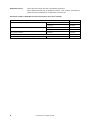
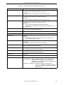
Documents related to 78K0R Microcontroller development tools (User’s Manual)
Document Name
CC78K0R Ver. 1.00 C Compiler
RA78K0R Ver. 1.00 Assembler Package
SM+ System Simulator
Document No.
Operation
U17838E
Language
U17837E
Operation
U17836E
Language
U17835E
Operation
U18010E
PM+ Ver. 6.20 Project Manager
ID78K0R-QB Ver. 3.20 Integrated Debugger
8
This manual
Operation
User’s Manual U17990EJ1V0UM
U17839E
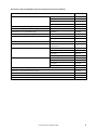
Documents related to V850 Microcontroller development tools (User’s Manual)
Document Name
CA850 Ver. 3.00 C Compiler Package
Document No.
Operation
U17293E
C Language
U17291E
Assembly Language
U17292E
Link Directives
U17294E
ID850 Ver. 3.00 Integrated Debugger
Operation
U17358E
ID850NW Ver. 3.00, 3.10 Integrated Debugger
Operation
U17369E
ID850NWC Ver. 2.51 Integrated Debugger
Operation
U16525E
ID850QB Ver. 3.20 Integrated Debugger
Operation
U17964E
SM+ System Simulator
Operation
U17246E
User Open Interface
U17663E
SM850 Ver. 2.50 System Simulator
Operation
U16218E
SM850 Ver. 2.00 or later System Simulator
External Part User Open Interface
U14873E
Specifications
RX850 Ver. 3.20 Real-Time OS
RX850 Pro Ver. 3.20 Real-Time OS
Basics
U13430E
Installation
U17419E
Technical
U13431E
Task Debugger
U17420E
Basics
U13773E
Installation
U17421E
Technical
U13772E
Task Debugger
U17422E
RD850 Ver. 3.01 Task Debugger
U13737E
AZ850 Ver. 3.30 System Performance Analyzer
U17423E
PG-FP4 Flash Memory Programmer
U15260E
TW850 Ver. 2.00 Performance Analysis Tuning Tool
U17241E
PM+ Ver. 6.20 Project Manager
This manual
User’s Manual U17990EJ1V0UM
9
CONTENTS
CHAPTER 1 GENERAL ... 23
1. 1 Overview ... 23
1. 2 Terminology ... 24
1. 3 Functions and Features ... 25
1. 4 Positioning of PM+ ... 26
1. 5 Operating Environments ... 27
CHAPTER 2 INSTALLATION ... 28
2. 1 Installing PM+ ... 28
2. 2 Uninstalling PM+ ... 28
CHAPTER 3 STARTING AND EXITING ... 29
3. 1 Starting ... 29
3. 2 Exiting ... 29
CHAPTER 4 QUICK TOUR ... 30
4. 1 Overview ... 30
4. 2 Creating Workspace ... 31
4. 3 Setting Options Related to Compilation ... 32
4. 4 Selecting Active Project ... 33
4. 5 Selecting Debugger ... 34
4. 6 Executing Build ... 35
4. 7 Other Settings ... 35
CHAPTER 5 METHOD OF OPERATION ... 36
5. 1 File Management ... 36
5. 1. 1
Creating a new file ... 37
5. 1. 2
Opening a existing file ... 37
5. 1. 3
Inserting a file ... 37
5. 1. 4
Closing a window ... 37
5. 1. 5
Opening a project file generated by the previous version ... 37
5. 1. 6
Creating a new workspace ... 38
5. 1. 7
Opening a workspace ... 57
5. 1. 8
Saving a workspace ... 64
5. 1. 9
Closing a workspace ... 64
5. 1. 10 Saving a file by overwriting ... 64
5. 1. 11 Saving a file with a new name ... 64
10
User’s Manual U17990EJ1V0UM
5. 1. 12 Saving all files ... 65
5. 1. 13 Saving all files (Changed files only) ... 65
5. 1. 14 Saving and Closing all files ... 65
5. 1. 15 Closing all windows ... 65
5. 1. 16 Closing all windows without saving ... 65
5. 1. 17 Changing a source file name ... 65
5. 1. 18 Saving all source files ... 66
5. 1. 19 Checking printing status ... 66
5. 1. 20 Printing ... 66
5. 1. 21 Printing directly ... 66
5. 1. 22 History of files ... 66
5. 1. 23 History of workspaces ... 66
5. 1. 24 Exiting PM+ ... 66
5. 2 Edit Functions ... 67
5. 2. 1
Canceling an edit operation ... 68
5. 2. 2
Canceling an [Undo] operation ... 68
5. 2. 3
Cutting off character strings ... 69
5. 2. 4
Copying character strings ... 69
5. 2. 5
Cutting off character strings (Cut for Append) ... 69
5. 2. 6
Copying character strings (Copy for Append) ... 69
5. 2. 7
Copying character strings as a screen image ... 70
5. 2. 8
Inserting the contents of clipboard ... 70
5. 2. 9
Inserting the contents of clipboard with specified format ... 70
5. 2. 10 Deleting character strings ... 71
5. 2. 11 Deleting a word ... 71
5. 2. 12 Deleting characters to the end of a word ... 71
5. 2. 13 Deleting a line ... 71
5. 2. 14 Deleting character strings to the top of line ... 71
5. 2. 15 Deleting character strings to the end of line ... 71
5. 2. 16 Selecting a word at the caret ... 72
5. 2. 17 Selecting a word to the left of the caret ... 72
5. 2. 18 Selecting a word to the right of the caret ... 72
5. 2. 19 Selecting a range to the top of line ... 72
5. 2. 20 Selecting a range to the end of line ... 72
5. 2. 21 Selecting entire contents ... 72
5. 2. 22 Grouping by keyword ... 73
5. 2. 23 Restoring color of grouping line ... 73
5. 2. 24 Creating function prototypes ... 73
5. 2. 25 Inserting a new object ... 73
5. 2. 26 Setting links for objects ... 73
5. 2. 27 Object ... 73
5. 3 Search Functions ... 74
5. 3. 1
Searching for a character string ... 75
User’s Manual U17990EJ1V0UM
11
5. 3. 2
Searching for a character string upward ... 75
5. 3. 3
Searching for a character string downward ... 75
5. 3. 4
Searching for a word upward ... 75
5. 3. 5
Searching for a word downward ... 76
5. 3. 6
Replacing a character string ... 76
5. 3. 7
Jumping to a specified line ... 76
5. 3. 8
Jumping to a specified line in a specified source file ... 76
5. 3. 9
Jumping to a marked line ... 76
5. 3. 10 Moving the caret to the top of line ... 76
5. 3. 11 Moving the caret to the end of line ... 76
5. 3. 12 Moving the caret to the top of file ... 77
5. 3. 13 Moving the caret to the end of file ... 77
5. 3. 14 Moving the caret to the index line ... 77
5. 3. 15 Moving the caret to the top layer ... 77
5. 3. 16 Moving the caret to the layer line of the same depth upward ... 78
5. 3. 17 Moving the caret to the layer line of the same depth downward ... 78
5. 3. 18 Moving the caret to the position before a jump ... 78
5. 3. 19 Moving the caret to the function definition line ... 79
5. 3. 20 Searching for matching braces ... 79
5. 3. 21 Searching for a character string within multiple files ... 79
5. 3. 22 Replacing a character string within multiple files ... 80
5. 3. 23 Searching for a character string within a project ... 81
5. 3. 24 Jumping to a desired line (tag jump) ... 82
5. 3. 25 Returning from a tag jump ... 83
5. 3. 26 Continuing a tag jump downward ... 83
5. 3. 27 Continuing a tag jump upward ... 83
5. 3. 28 Moving the caret one word to the right ... 83
5. 3. 29 Moving the caret one word to the left ... 84
5. 3. 30 Moving the caret up by one line ... 84
5. 3. 31 Moving the caret down by one line ... 84
5. 3. 32 Moving the caret one character to the right ... 84
5. 3. 33 Moving the caret one character to the left ... 85
5. 3. 34 Making the Search Character String Specification combo box active ... 85
5. 4 Layer Management ... 86
12
5. 4. 1
Promoting layers ... 87
5. 4. 2
Demoting Layers ... 88
5. 4. 3
Expanding or collapsing one of the lower layers ... 88
5. 4. 4
Expanding one of the lower layers ... 88
5. 4. 5
Collapsing one of the lower layers ... 89
5. 4. 6
Expanding all of the lower layers ... 90
5. 4. 7
Expanding all of the layers ... 90
5. 4. 8
Collapsing all of the layers ... 90
5. 4. 9
Expanding a specified number of layers ... 90
User’s Manual U17990EJ1V0UM
5. 4. 10 Collapsing a specified number of layers ... 90
5. 4. 11 Displaying the top layer only ... 91
5. 4. 12 Displaying the first and second layers ... 91
5. 4. 13 Displaying the first to third layers ... 91
5. 4. 14 Displaying the first to fourth layers ... 91
5. 4. 15 Displaying the first to fifth layers ... 91
5. 4. 16 Collapsing a layer at the caret ... 91
5. 4. 17 Applying a layer rule ... 92
5. 5 Display Functions ... 93
5. 5. 1
Displaying a list of functions ... 93
5. 5. 2
Displaying a list of layers ... 93
5. 5. 3
Displaying the standard bar ... 93
5. 5. 4
Displaying the build bar ... 93
5. 5. 5
Displaying the option bar ... 93
5. 5. 6
Displaying the external tool bar ... 94
5. 5. 7
Displaying the status bar ... 94
5. 5. 8
Displaying the [Project] window ... 94
5. 5. 9
Displaying the [OutPut] window ... 94
5. 5. 10 Displaying an object as contents or icon ... 94
5. 5. 11 Displaying all objects as contents ... 94
5. 5. 12 Displaying all objects as icons ... 94
5. 6 Project Management ... 95
5. 6. 1
Creating a project file ... 95
5. 6. 2
Selecting active project ... 96
5. 6. 3
Adding a new project to a workspace ... 96
5. 6. 4
Inserting a project into a workspace ... 115
5. 6. 5
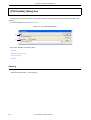
CVS update ... 115
5. 6. 6
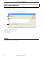
CVS commit ... 115
5. 6. 7
CVS log ... 115
5. 6. 8
CVS status ... 115
5. 6. 9
CVS comparison ... 116
5. 6. 10 Exporting a make file ... 116
5. 6. 11 Setting project information ... 116
5. 6. 12 Adding a source file ... 116
5. 6. 13 Adding a project-related file ... 116
5. 6. 14 Adding other files ... 116
5. 6. 15 Making the Active Project Selection combo box active ... 116
5. 6. 16 Changing a project group name ... 117
5. 6. 17 Changing a project title ... 117
5. 6. 18 Changing the tools used ... 117
5. 6. 19 Moving a project ... 117
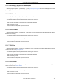
5. 7 Build Functions ... 118
5. 7. 1
Building and Debugging ... 118
User’s Manual U17990EJ1V0UM
13
5. 7. 2
Rebuilding and Debugging ... 119
5. 7. 3
Compiling ... 119
5. 7. 4
Building ... 119
5. 7. 5
Stopping build ... 119
5. 7. 6
Rebuilding ... 120
5. 7. 7
Batch building ... 120
5. 7. 8
Batch Rebuilding ... 120
5. 7. 9
Updating dependency relationship of files ... 120
5. 7. 10 Cleaning ... 120
5. 7. 11 Editing ... 120
5. 7. 12 Debugging ... 121
5. 7. 13 Downloading multiple load module files ... 121
5. 7. 14 Selecting build mode ... 121
5. 7. 15 Setting build options ... 121
5. 7. 16 Setting batch build ... 121
5. 7. 17 Making the Build Mode Selection combo box active ... 121
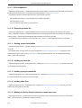
5. 8 Tool Management ... 122
5. 8. 1
Setting options for each tool ... 122
5. 8. 2
Selecting OS to be used ... 122
5. 8. 3
Dumping the load module file or the object file ... 123
5. 8. 4
Selecting and setting the debugger to be used ... 123
5. 8. 5
Registering external tools ... 123
5. 8. 6
Starting up external tools ... 123
5. 8. 7
Comparing files ... 123
5. 8. 8
Inserting device file ... 123
5. 8. 9
Setting environment ... 124
5. 8. 10 Setting font ... 124
5. 8. 11 Customizing settings ... 124
5. 8. 12 Recording key operations ... 124
5. 8. 13 Playing back key operations ... 125
5. 8. 14 Saving key operations ... 125
5. 8. 15 Commands corresponding to key operations ... 125
5. 8. 16 Reading key operations ... 137
5. 8. 17 Executing macro ... 137
5. 8. 18 Registering macro ... 137
5. 8. 19 Executing registered macro ... 137
5. 9 Window Management ... 138
14
5. 9. 1
Arranging windows so they overlap ... 138
5. 9. 2
Arranging windows horizontally ... 138
5. 9. 3
Arranging windows vertically ... 138
5. 9. 4
Splitting a window ... 138
5. 9. 5
Moving the caret to the other split window ... 139
5. 9. 6
Activating the next window ... 139
User’s Manual U17990EJ1V0UM
5. 9. 7
Activating the previous window ... 139
5. 9. 8
Displaying a list of windows ... 139
5. 10 Help Functions ... 140
5. 10. 1 Starting up the PM+ help ... 140
5. 10. 2 Displaying the help of the Main window ... 140
5. 10. 3 Displaying the help of a current window ... 140
5. 10. 4 Displaying a list of shortcut keys ... 140
5. 10. 5 Accessing to NEC Electronics microprocessor web site ... 140
5. 10. 6 Starting up a external help 1 ... 140
5. 10. 7 Starting up a external help 2 ... 141
5. 10. 8 Starting up a external help 3 ... 141
5. 10. 9 Displaying the version information about PM+ ... 141
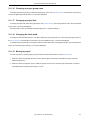
CHAPTER 6 WINDOW REFERENCE ... 142
6. 1 Window Composition ... 142
6. 2 Input Rules ... 147
6. 3 Explanation of Windows/Dialog boxes ... 148
Main window ... 149
[Project] window ... 167
Edit window ... 179
Search result display window ... 187
[OutPut] window ... 189
[Open] dialog box ... 191
[Insert File] dialog box ... 194
[Open Workspace] dialog box ... 197
[Save As] dialog box ... 199
[Save Source Files Options] dialog box ... 202
[Change Source File Names] dialog box ... 204
[Change Selected Source File Name] dialog box ... 207
[Change Selected Source File Names] dialog box ... 209
[Set Comment Mark] dialog box ... 211
[Print] dialog box ... 213
[Font] dialog box (Print) ... 216
[Set Header/Footer] dialog box ... 218
[Grouping by Keyword] dialog box ... 222
[Select the way of Function Prototypes] dialog box ... 225
[Find String] dialog box ... 228
[Replace String] dialog box ... 233
[Jump to Specified Line] dialog box ... 238
[Jump to Specified Line in the Source file] dialog box ... 240
[Mark Jump] dialog box ... 242
[Find in Files] dialog box ... 245
[Replace in Files] dialog box ... 250
User’s Manual U17990EJ1V0UM
15
[Expand to Specified Layer] dialog box ... 255
[Collapse to Specified Layer] dialog box ... 257
[Set Layer Rule] dialog box ... 259
[Function List] dialog box ... 263
[Save the Function List] dialog box ... 266
[Layer List] dialog box ... 268
[Select Active Project] dialog box ... 270
[Insert Project] dialog box ... 272
[CVS Update] dialog box ... 274
[CVS Commit] dialog box ... 276
[CVS Log] dialog box ... 278
[CVS Status] dialog box ... 280
[Project Settings] dialog box ... 282
[Add Source Files] dialog box ... 288
[Add Project Related Files] dialog box ... 290
[Add Other Files] dialog box ... 292
[Project Group Name] dialog box ... 294
[Project Title] dialog box ... 296
[Tool Version Settings] dialog box ... 298
[Tool Version Detail Setting] dialog box ... 301
[Properties] dialog box ... 303
[Add New Memo] dialog box ... 305
[Startup File] dialog box ... 306
[Copy Startup File from] dialog box ... 308
[Startup File to register] dialog box ... 310
[Link Directive File] dialog box ... 312
[Copy Link Directive File from] dialog box ... 314
[Link Directive File to register] dialog box ... 316
[Select Project] dialog box ... 318
[Edit Batch Build Settings] dialog box ... 320
[Build Mode] dialog box ... 322
[Add Build Mode] dialog box ... 324
[Build Settings] dialog box ... 326
[Add Command] dialog box ... 331
[Edit Command] dialog box ... 332
[Select OS] dialog box ... 334
[dump850] dialog box ... 336
[Debugger Settings] dialog box ... 338
[Register External Tool] dialog box ... 341
[Select External Tool] dialog box ... 343
[File Compare] dialog box ... 345
[PM+ Settings] dialog box ... 348
[User Setting] dialog box ... 371
16
User’s Manual U17990EJ1V0UM
[Font] dialog box ... 373
[Customize] dialog box ... 375
[Edit User keyword] dialog box ... 383
[Edit C Language's reserve words] dialog box ... 385
[Save the Key Operation] dialog box ... 387
[Load the Macro File] dialog box ... 389
[Play back the Macro File] dialog box ... 391
[Entry Macro Files] dialog box ... 393
[Add the Macro file] dialog box ... 395
[Change the Macro file] dialog box ... 397
[Window List] dialog box ... 399
[Shortcut List] dialog box ... 401
[About PM+] dialog box ... 403
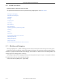
CHAPTER 7 MESSAGES ... 405
7. 1 Display Format ... 405
7. 2 Fatal Error ... 406
7. 3 Operation Error ... 415
7. 4 Question ... 430
7. 5 Information ... 438
APPENDIX A SAMPLE LINK DIRECTIVE FILE ... 441
APPENDIX B QUANTITATIVE LIMIT LIST ... 444
INDEX ... 445
User’s Manual U17990EJ1V0UM
17
LIST OF FIGURES
Figure No.
Title and Page
1-1
Main Window of PM+ ... 24
1-2
Relationship between Software for Program Development and PM+ ... 26
3-1
Main Window At Starting ... 29
4-1
Operation Flow until Debugging ... 30
4-2
Setting Options Related to Compilation ... 32
4-3
Selecting Active Project ... 33
4-4
Selecting Debugger ... 34
5-1
Wizard Flow for Creating New Workspace ... 39
5-2
Wizard-Format Dialog Box for Creating ANew Workspace ... 40
5-3
[New Workspace - Step 1/9 [Workspace Information]] Dialog Box ... 42
5-4
[New Workspace - Step 2/9 [Select Tools]] Dialog Box ... 44
5-5
[New Workspace - Step 3/9 [Select Real-Time OS]] Dialog Box ... 46
5-6
[New Workspace - Step 4/9 [Startup File]] Dialog Box ... 47
5-7
[New Workspace - Step 5/9 [Register Mode]] Dialog Box ... 49
5-8
[New Workspace - Step 6/9 [LinkDirective File]] Dialog Box ... 51
5-9
[New Workspace - Step 7/9 [Setup Source Files]] Dialog Box ... 53
5-10
[New Workspace - Step 8/9 [Select Debugger]] Dialog Box ... 55
5-11
[New Workspace - Step 9/9 [Confirmation]] Dialog Box ... 56
5-12
Wizard-Format Dialog Box for Updating The Project Information ... 58
5-13
[Project Settings - Step 1/3 [Project Information]] Dialog Box ... 59
5-14
[Project Settings - Step 2/3 [Select Tools]] Dialog Box ... 61
5-15
[Project Settings - Step 3/3 [Setup Source Files]] Dialog Box ... 63
5-16
[History of Replace in files] Window ... 80
5-17
Search result display Window ... 81
5-18
Promoting Layers ... 87
5-19
Demoting Layer ... 88
5-20
Expanding One of the Lower Layers ... 89
5-21
Collapsing One of the Lower Layers ... 89
5-22
Expanding All of the Lower Layers ... 90
5-23
The Wizard Flow of Add New Project Dialog Boxes ... 97
5-24
Wizard-Format Dialog Box for Addind A New Project ... 98
5-25
[Add New Project - Step 1/9 [Project Information]] Dialog Box ... 100
5-26
[Add New Project - Step 2/9 [Select Tools]] Dialog Box ... 102
5-27
[Add New Project - Step 3/9 [Select Real-Time OS]] Dialog Box ... 104
5-28
[Add New Project - Step 4/9 [Startup File]] Dialog Box ... 105
5-29
[Add New Project - Step 5/9 [Register Mode]] Dialog Box ... 107
5-30
[Add New Project - Step 6/9 [LinkDirective File]] Dialog Box ... 109
5-31
[Add New Project - Step 7/9 [Setup Source Files]] Dialog Box ... 111
5-32
[Add New Project - Step 8/9 [Select Debugger]] Dialog Box ... 113
5-33
[Add New Project - Step 9/9 [Confirmation]] Dialog Box ... 114
6-1
Window Composition of PM+ ... 146
6-2
Main Window ... 149
6-3
Status Bar ... 165
6-4
[Project] Window ... 167
18
User’s Manual U17990EJ1V0UM
6-5
[Project] Window - [File] Tab ... 168
6-6
[Project] Window - [Memo] Tab ... 175
6-7
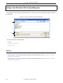
Position where a File is Dropped in a Workspace for which Project is Registered ... 177
6-8
Edit Window ... 179
6-9
Search Result Display Window ... 187
6-10
[OutPut] Window ... 189
6-11
[Open] Dialog Box ... 191
6-12
[Insert File] Dialog Box ... 194
6-13
[Open Workspace] Dialog Box ... 197
6-14
[Save As] Dialog Box ... 199
6-15
[Save Source Files Options] Dialog Box ... 202
6-16
[Change Source File Names] Dialog Box ... 204
6-17
[Change Selected Source File Name] Dialog Box ... 207
6-18
[Change Selected Source File Names] Dialog Box ... 209
6-19
[Set Comment Mark] Dialog Box ... 211
6-20
[Print] Dialog Box ... 213
6-21
[Font] Dialog Box (Print) ... 216
6-22
[Set Header/Footer] Dialog Box ... 218
6-23
[Grouping by Keyword] Dialog Box ... 222
6-24
[Select the way of Function Prototypes] Dialog Box ... 225
6-25
[Find String] Dialog Box ... 228
6-26
[Find String] Dialog Box (Mini) ... 229
6-27
[Replace String] Dialog Box ... 233
6-28
[Replace String] Dialog Box (Mini) ... 236
6-29
[Jump to Specified Line] Dialog Box ... 238
6-30
[Jump to Specified Line in the Source file] Dialog Box ... 240
6-31
[Mark Jump] Dialog Box ... 242
6-32
[Find in Files] Dialog Box ... 245
6-33
[Find in Files] Dialog Box (Details) ... 245
6-34
[Select Folder] Dialog Box ... 246
6-35
[Replace in Files] Dialog Box ... 250
6-36
[Expand to Specified Layer] Dialog Box ... 255
6-37
[Collapse to Specified Layer] Dialog Box ... 257
6-38
[Set Layer Rule] Dialog Box ... 259
6-39
[Function List] Dialog Box ... 263
6-40
[Save the Function List] Dialog Box ... 266
6-41
[Layer List] Dialog Box ... 268
6-42
[Select Active Project] Dialog Box ... 270
6-43
[Insert Project] Dialog Box ... 272
6-44
[CVS Update] Dialog Box ... 274
6-45
[CVS Commit] Dialog Box ... 276
6-46
[CVS Log] Dialog Box ... 278
6-47
[CVS Status] Dialog Box ... 280
6-48
[Project Settings] Dialog Box ... 282
6-49
[Project Settings] Dialog Box - [Project Information] Tab ... 283
6-50
[Project Settings] Dialog Box - [Source File] Tab ... 284
6-51
[Project Settings] Dialog Box - [Tool Version Settings] Tab ... 285
6-52
[Add Source Files] Dialog Box ... 288
User’s Manual U17990EJ1V0UM
19
6-53
[Add Project Related Files] Dialog Box ... 290
6-54
[Add Other Files] Dialog Box ... 292
6-55
[Project Group Name] Dialog Box ... 294
6-56
[Project Title] Dialog Box ... 296
6-57
[Tool Version Settings] Dialog Box ... 298
6-58
[Tool Version Detail Setting] dialog box ... 301
6-59
[Properties] Dialog Box ... 303
6-60
[Add New Memo] Dialog Box ... 305
6-61
[Startup File] Dialog Box ... 306
6-62
[Copy Startup File from] Dialog Box ... 308
6-63
[Startup File to register] Dialog Box ... 310
6-64
[Link Directive File] Dialog Box ... 312
6-65
[Copy Link Directive File from] Dialog Box ... 314
6-66
[Link Directive File to register] Dialog Box ... 316
6-67
[Select Project] Dialog Box ... 318
6-68
[Edit Batch Build Settings] Dialog Box ... 320
6-69
[Build Mode] Dialog Box ... 322
6-70
[Add Build Mode] Dialog Box ... 324
6-71
[Build Settings] Dialog Box ... 326
6-72
[Build Settings] Dialog Box - [Build] Tab ... 327
6-73
[Build Settings] Dialog Box - [Pre Build Process] Tab ... 328
6-74
[Build Settings] Dialog Box - [After Build Process] Tab ... 329
6-75
[Add Command] Dialog Box ... 331
6-76
[Edit Command] Dialog Box ... 332
6-77
[Select OS] Dialog Box ... 334
6-78
[dump850] Dialog Box ... 336
6-79
[Debugger Settings] Dialog Box ... 338
6-80
[Register External Tool] Dialog Box ... 341
6-81
[Select External Tool] Dialog Box ... 343
6-82
[File Compare] Dialog Box ... 345
6-83
[File Compare] Dialog Box (Mini) ... 345
6-84
[PM+ Settings] Dialog Box ... 348
6-85
[PM+ Settings] Dialog Box - [Workspace] Tab ... 349
6-86
[PM+ Settings] Dialog Box - [External Editor] Tab ... 350
6-87
[PM+ Settings] Dialog Box - [File] Tab ... 351
6-88
[PM+ Settings] Dialog Box - [Recent] Tab ... 354
6-89
[PM+ Settings] Dialog Box - [Source File by idl File] Tab ... 356
6-90
[PM+ Settings] Dialog Box - [Window] Tab ... 358
6-91
[PM+ Settings] Dialog Box - [Path] Tab ... 359
6-92
[PM+ Settings] Dialog Box - [Edit] Tab ... 361
6-93
[PM+ Settings] Dialog Box - [View] Tab ... 363
6-94
[PM+ Settings] Dialog Box - [Layer] Tab ... 366
6-95
[PM+ Settings] Dialog Box - [Scroll] Tab ... 367
6-96
[PM+ Settings] Dialog Box - [Find/ Replace] Tab ... 368
6-97
[User Setting] Dialog Box ... 371
6-98
[Font] Dialog Box ... 373
6-99
[Customize] Dialog Box ... 375
6-100
[Customize] Dialog Box - [Keyboard] Tab ... 376
20
User’s Manual U17990EJ1V0UM
6-101
[Customize] Dialog Box - [Menu] Tab ... 377
6-102
[Customize] Dialog Box - [Toolbar] Tab ... 378
6-103
[Customize] Dialog Box - [User Menu] Tab ... 380
6-104
[Customize] Dialog Box - [Keyword] Tab ... 381
6-105
[Edit User keyword] Dialog Box ... 383
6-106
[Edit C Language's reserve words] Dialog Box ... 385
6-107
[Save the Key Operation] Dialog Box ... 387
6-108
[Load the Macro File] Dialog Box ... 389
6-109
[Play back the Macro File] Dialog Box ... 391
6-110
[Entry Macro Files] Dialog Box ... 393
6-111
[Add the Macro file] Dialog Box ... 395
6-112
[Change the Macro file] Dialog Box ... 397
6-113
[Window List] Dialog Box ... 399
6-114
[Shortcut List] Dialog Box ... 401
6-115
[About PM+] Dialog Box ... 403
7-1
Message Dialog Box ... 405
User’s Manual U17990EJ1V0UM
21
LIST OF TABLES
List No.
Title and Page
5-1
Messages on the History of Replace in files Window ... 80
5-2
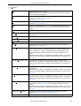
Command Format for Key Board Macro (File menu) ... 126
5-3
Command Format for Key Board Macro (Edit menu) ... 127
5-4
Command Format for Key Board Macro (Find menu) ... 128
5-5
Command Format for Key Board Macro (Layer menu) ... 130
5-6
Command Format for Key Board Macro (jump-related) ... 131
5-7
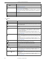
Command Format for Key Board Macro (Help menu) ... 132
5-8
Command Format for Key Board Macro (no menu) ... 133
5-9
Command Format for Key Board Macro (control command-related) ... 134
6-1
Window/Dialog Box List ... 142
6-2
Standard Bar ... 162
6-3
Build Bar ... 163
6-4
Option Bar (78K0R Series) ... 164
6-5
Option Bar (V850 Series) ... 164
7-1
The Meaning of each Message Type ... 405
B-1
Quantitative Limit List ... 444
22
User’s Manual U17990EJ1V0UM
CHAPTER 1 GENERAL
CHAPTER 1 GENERAL
1. 1 Overview
The project manager (PM+) is an integrated development environment platform that is used to efficiently develop user
programs for NEC Electronics 8-/16-bit microcontrollers for embedded control, the 78K0R Series and NEC Electronics 32bit microcontrollers for embedded control, the V850 Series.
A series of operations in user program development can be performed from PM+ such as editor startup, builder startup,
and debugger startup.
User’s Manual U17990EJ1V0UM
23
CHAPTER 1 GENERAL
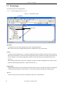
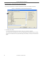
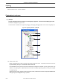
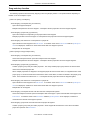
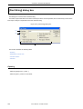
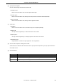
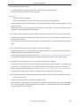
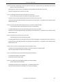
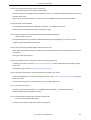
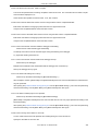
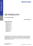
1. 2 Terminology
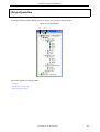
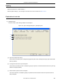
The terms used for PM+ are defined below.
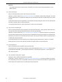
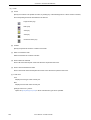
Figure 1-1 shows the image of the Main window.
Figure 1-1 Main Window of PM+
Workspace
Project group
Project
Workspace
A "workspace" is the unit which manages the file name of multiple project files.
PM+ saves the file names of multiple project files into a workspace file (*.prw), and refers to it.
Project
A "project" is a unit managed by PM+. It indicates an application system developed under PM+ and its environment.
PM+ saves the information, such as the source files, target device name, tool options for creating a load module, and
editor or debugger, to be used for the application system into each project file (*.prj) as "project information" and
refers to it.
Build or debug is performed in project units. Therefore, the project to be built or debugged have to be set as "active
project" (by selecting the [Project] menu -> [Select Active Project...] ).
Project group
Multiple registered projects can be arranged with related projects in a group. Note that each project to be registered
in a project group must target a common device (i.e. only one device file can be assigned to a project group).
IDL file
An IDL file is a file used to save the layer information for PM+ (idea-L information file).
24
User’s Manual U17990EJ1V0UM
CHAPTER 1 GENERAL
1. 3 Functions and Features
The major functions and features of PM+ are as follows:
- Managing multiple projects
PM+ can manage multiple project files collectively by using concepts such as workspace and project group.
- Starting a builder
PM+ can be used to start tools required for generating application systems (a compiler, assembler, linker, ROMization processor necessary for storing programs in ROM, and a hex converter).
- Starting editor
PM+ can be used to create or modify the source files to be used for a project by the editor function which PM+ provides. Furthermore, an external editor can also be registered and started form PM+.
- Starting a debugger
PM+ can be used to start NEC Electronics debugger or system simulator. When a correction of the source program is issued from the debugger, PM+ displays a specified line of the specified file.
- Registering and executing external tools
Other applications the user often uses can be included in the menu of PM+ and started from this menu.
- Linking with a source management tool
Version management of the source program in the software development process can be performed more easily by
linking with a source management tool.
- Linking with a source analysis tool
Quality management of the source program in the software development process can be performed more easily by
linking with a commercial source analysis tool.
- Correspondence of comments with specification
PM+ supports a function that is effective in adjustment of specification at the processes of its review (idea processor function). This makes it possible to reflect the adjusted contents to a source program as comments.
User’s Manual U17990EJ1V0UM
25
CHAPTER 1 GENERAL
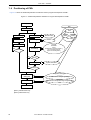
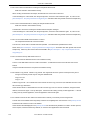
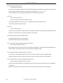
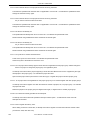
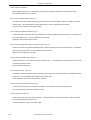
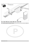
1. 4 Positioning of PM+
Figure 1-2 shows the relationship between the software used for program development and PM+.
Figure 1-2 Relationship between Software for Program Development and PM+
Product planning
PM+
System design
Edit
Hardware design
Software design
Real-time OS
Production
Cording
Editor
Inspection
Yes
Compilling/
Assembling
Error?
Build
Debug
Compiler
Assembler
Linker
ROM-ization processor [Note 1]
Hex converter [Note 2]/
Object converter [Note 1]
No
Yes
Error?
No
Debug
Yes
System simulater
Bug?
No
Integrated debugger
System
debugging
Performance analyzer [Note 2]
System evaluation
Performance AnalysisTuning Tool [Note 2]
Commercialization
[Note 1] 78K0R Series only
[Note 2] V850 Series only
26
User’s Manual U17990EJ1V0UM
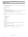
CHAPTER 1 GENERAL
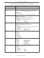
1. 5 Operating Environments
The following environments are required in order to use PM+.
[Caution]
The operation of PM+ is not guaranteed in a network environment. Do not use PM+ in a network environment.
(1) Host machine
- CPU:
Pentium IITM 400MHz or higher
- Memory:
128 Mbytes or more
- OS:
Windows®98 Second Edition, WindowsMe, Windows2000,
WindowsXP Professional, WindowsXP Home Edition
[Caution]
Regardless of which OS is used, higher and the latest Service Pack must be installed.
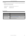
(2) DLL
The following DLL files provided by Microsoft Corp. are required.
- mfc42.dll V6.0.8665.0 or more (It is provided when PM+ is installed.)
- msvctr.dll V6.1 or more (It is provided when PM+ is installed.)
- ComCtl32.dll V5.81 or more (It is necessary to install in addition to PM+.)
(3) Related development tools
[78K0R Series]
- Compiler/Assembler:
Compiler:
CC78K0R (V1.00 or later)
Assembler:
RA78K0R (V1.00 or later)
- Integrated debugger/System simulater
Integrated debugger:
ID78K0R-QB (V3.20 or later)
System simulater:
SM+ for 78K0R (V2.10 or later) (Under development)
- Device File
A device file of target device to be used
[V850 Series]
- Compiler
CA850 (V3.00 or later)
- Integrated debugger/System simulater
Integrated debugger: ID850 (V3.10 or later), ID850NW (V3.10 or later), or ID850QB (V3.10 or later)
System simulater:
SM850 (V3.00 or later), or SM+ for V850 (V2.00 or later)
- Device File
A device file of target device to be used
- Performance analysis tuning tool (if necessary)
TW850 (V2.00 or later)
User’s Manual U17990EJ1V0UM
27
CHAPTER 2 INSTALLATION
CHAPTER 2 INSTALLATION
2. 1 Installing PM+
PM+ is included with an assembler package (RA78K0R) or a compiler package (CA850). When RA78K0R or CA850
are installed, PM+ can be also installed if necessary, as it is supplied in the same package.
For the details on how to install the assembler package or the compiler package, refer to the user's manual of each tool.
2. 2 Uninstalling PM+
To uninstall PM+, start "Add or Remove Programs" ("Add/Remove Programs" in Windows other than Windows XP) on
the Control Panel of Windows and select the following items.
- NEC EL PM+ V6.20
- NEC EL PM+ V6.20 Documents
28
User’s Manual U17990EJ1V0UM
CHAPTER 3 STARTING AND EXITING
CHAPTER 3 STARTING AND EXITING
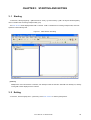
3. 1 Starting
To start PM+, select [Programs] -> [NEC Electronics Tools] -> [Latest Version] -> [PM+ V6.00] from Windows [Start]
menu or double-click an existing workspace file(*.prw).
The Main window will be displayed after PM+ is started. If PM+ is started from an existing workspace file, that workspace file is automatically read.
Figure 3-1 Main Window At Starting
[Caution]
Multiple PM+ cannot be activated. Therefore, if an attempt is made to start PM+ while PM+ has already run, alreadyrunning PM+ will be displayed on the forefront.
3. 2 Exiting
To exit PM+, select the [File] menu -> [Exit PM+] on the Main window or click the [Close] button.
User’s Manual U17990EJ1V0UM
29
CHAPTER 4 QUICK TOUR
CHAPTER 4 QUICK TOUR
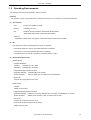
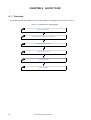
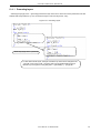
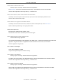
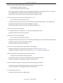
4. 1 Overview
This chapter describes the operation flow from project registration to debugging for first-time users of PM+.
Figure 4-1 Operation Flow until Debugging
Creating Workspace
Setting Options Related to Compilation
Selecting Active Project
Selecting Debugger
Executing Build
Other Settings
30
User’s Manual U17990EJ1V0UM
CHAPTER 4 QUICK TOUR
4. 2 Creating Workspace
The development flow using PM+ begins with the registration of a project.
In order to register a project, a "workspace" to manage it must be created.
A workspace can be created using one of the following three methods.
Refer to the appropriate method in accordance with the environment used.
(1) Creating a new workspace
A new workspace can be created by specifying the necessary project information in order in a wizard format.
[Refer to]: "5. 1. 6 Creating a new workspace"
(2) Creating a workspace using a project file created by the PM (V3.xx) or PM plus (V5.xx)
In PM+, a workspace can be created by reading a project file or workspace file created by the PM (V3.xx) or PM
plus (V5.xx).
[Refer to]: "5. 1. 5 Opening a project file generated by the previous version"
(3) Creating a workspace using a project file created by a NEC Electronics debugger/simulator
A workspace can be created by using a project file that has been updated the project information for PM+ in a wizard format.
[Refer to]: "5. 1. 7 Opening a workspace"
Multiple projects can be registered to one workspace.
[Refer to]: "5. 6. 3 Adding a new project to a workspace"
User’s Manual U17990EJ1V0UM
31
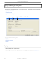
CHAPTER 4 QUICK TOUR
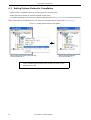
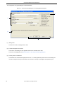
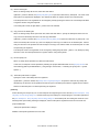
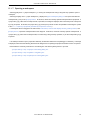
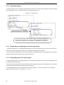
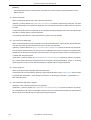
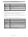
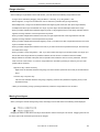
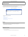
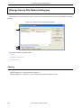
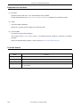
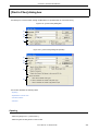
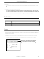
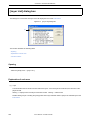
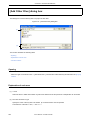
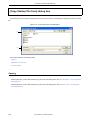
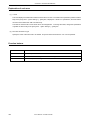
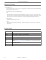
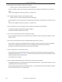
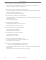
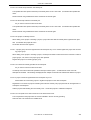
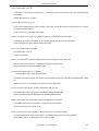
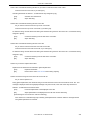
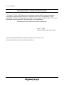
4. 3 Setting Options Related to Compilation
Options related to compilation can be set for each project from the [Tool] menu.
Refer to the user's manual of the compiler for details of each option.
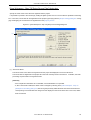
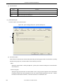
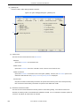
To set option individually in source file units, select the appropriate file on the [Project] window and click the right mouse
button. When option is set individually, the icon of the source file will change to green on the [Project] window.
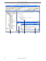
Figure 4-2 Setting Options Related to Compilation
Click the right mouse button after selecting
the source file (test1.c)
Options are set individually
per source file (test1.c)
In PM+, individual options related to the compiler can be set for each
registered source file.
32
User’s Manual U17990EJ1V0UM
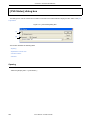
CHAPTER 4 QUICK TOUR
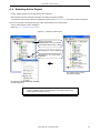
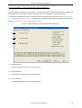
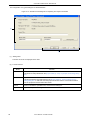
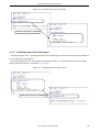
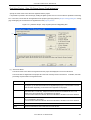
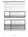
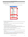
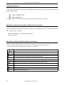
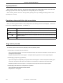
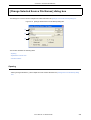
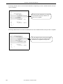
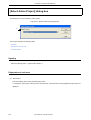
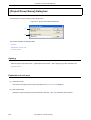
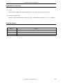
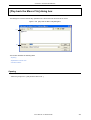
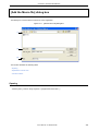
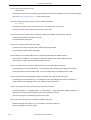
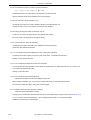
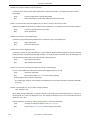
4. 4 Selecting Active Project
In PM+, multiple projects can be registered to one workspace.
When build is executed, therefore, the project to be built must be pre-specified.
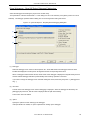
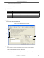
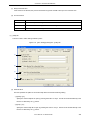
To specify the active project, select the appropriate project on the [Project] window and click the right mouse button.
The icon of the project will change from gray to pink when selected as an active project.
Only an active project is built or debugged.
[Refer to]: "5. 6. 2 Selecting active project"
Figure 4-3 Selecting Active Project
Project group name:
Multiple projects can be managed
(the example shows main, Library).
Library files, etc. can be registered.
Specifications, etc. can be freely
registered.
The project (Library) is set
as the active project.
Click the right mouse button after selecting
the project (Library).
In PM+, multiple projects can be registered or managed together with
related projects in a project group.
User’s Manual U17990EJ1V0UM
33
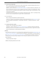
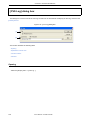
CHAPTER 4 QUICK TOUR
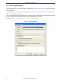
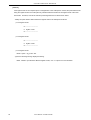
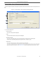
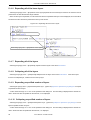
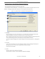
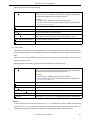
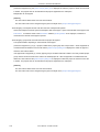
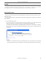
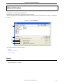
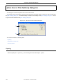
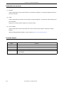
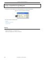
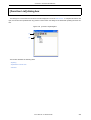
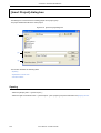
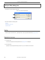
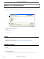
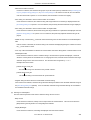
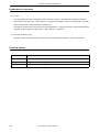
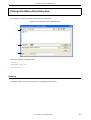
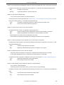
4. 5 Selecting Debugger
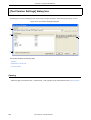
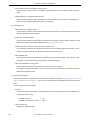
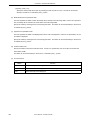
Selecting the [Tool] menu -> [Debugger Settings...] displays the [Debugger Settings] dialog box in which the debugger
to be used can be set.
In this dialog box, all the NEC Electronics debuggers and simulators that are specified as the tools to be used and their
versions can be displayed and selected.
After executing build by selecting the [Build] menu -> [Build and Debug], the debugger that is set here starts up automatically and downloads a load module file at the same time to facilitate the debug operation.
[Refer to]: [Debugger Settings] dialog box, "5. 6. 18 Changing the tools used"
Figure 4-4 Selecting Debugger
34
User’s Manual U17990EJ1V0UM
CHAPTER 4 QUICK TOUR
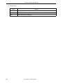
4. 6 Executing Build
Selecting [Build] menu -> [Build and Debug] starts batch processing from build to debug for the active project.
If build ends correctly, the set debugger starts up automatically and loads the created load module file (if the debugger
does not have to be started up, execute build by selecting the [Build] menu -> [Build]). At this time, a make file (*.mak) is
also created automatically in default condition.
The messages that are output from the language processing tool during build execution are displayed on the [OutPut]
window. At this time, place the caret on the error/warning line that is displayed and double-click the left mouse button to
open the source file and tag-jump to the relevant error/warning line.
[Refer to]: "5. 7. 1 Building and Debugging"
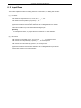
4. 7 Other Settings
There are many other functions is provided to enable more efficient and smooth execution of the debug operation flow
using the PM+ platform.
- Setting the layer rule
[Refer to]: "5. 4. 17 Applying a layer rule"
- Registration of external tools and customization of menu/toolbars
[Refer to]: "5. 8. 5 Registering external tools", "5. 8. 11 Customizing settings"
- Word-based searching in all the source files of the project
[Refer to]: "5. 3. 23 Searching for a character string within a project"
- Setting the tool to be used
[Refer to]: "5. 6. 18 Changing the tools used"
User’s Manual U17990EJ1V0UM
35
CHAPTER 5 METHOD OF OPERATION
CHAPTER 5 METHOD OF OPERATION
5. 1 File Management
Operations related to the file handling in PM+ are shown below.
The operations described in this section are performed using the [File] menu in the Main window.
- Creating a new file
- Opening a existing file
- Inserting a file
- Closing a window
- Opening a project file generated by the previous version
- Creating a new workspace
- Opening a workspace
- Saving a workspace
- Closing a workspace
- Saving a file by overwriting
- Saving a file with a new name
- Saving all files
- Saving all files (Changed files only)
- Saving and Closing all files
- Closing all windows
- Closing all windows without saving
- Changing a source file name
- Saving all source files
- Checking printing status
- Printing
- Printing directly
- History of files
- History of workspaces
- Exiting PM+
36
User’s Manual U17990EJ1V0UM
CHAPTER 5 METHOD OF OPERATION
5. 1. 1 Creating a new file
Selecting the [File] menu -> [New] opens a new Edit window.
Up to 64 Edit window can be opened together with the Search result display window and the [OutPut] window.
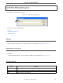
5. 1. 2 Opening a existing file
Selecting the [File] menu -> [Open] opens the [Open] dialog box to open a selected file.
5. 1. 3 Inserting a file
Selecting the [File] menu -> [Insert file...] opens the [Insert File] dialog box to insert a specified file at the caret position
in the currently active Edit window.
The files that can be inserted are as follows:
- A IDL file
- A text file
5. 1. 4 Closing a window
Selecting the [File] menu -> [Close] closes the window being edited. If the contents of the window has been modified, a
message for confirming whether to save the changes is displayed.
Note that if there are any files with read-only having the same name, those files will all be closed.
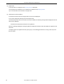
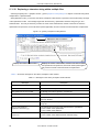
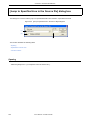
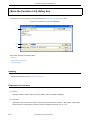
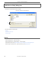
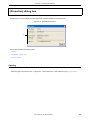
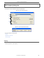
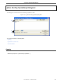
5. 1. 5 Opening a project file generated by the previous version
Selecting the [File] menu -> [Open Workspace...] opens the [Open Workspace] dialog box to read a project file (*.prj) or
workspace file (*.prw) that was generated by the previous version, PM (V3.xx) or PM plus (V5.xx).
At this time, PM+ outputs a message that prompt the user to confirm that PM+ is going to convert the file format into the
workspace file format of PM+ (V6.xx). Click the [OK] button; the file format is then automatically converted as follows and
read.
- Workspace file name (If a project file is read);
"project file name + extension (*.prw)"
- Project group name (If a project file is read);
"device series name" (e.g. V850 Series)
- Project title name (If a project file is read);
If a title setting has been performed with the read file, it remains as its title.
If no title setting has been performed with the read file, the project file name is set as its title.
- [Select Debugger] information ( Only PM plus (V5.xx));
Deleted
- Version information;
PM+ (V6.xx)
The workspace name can not be renamed. However, the project group name or the project title name can be renamed
User’s Manual U17990EJ1V0UM
37
CHAPTER 5 METHOD OF OPERATION
by clicking the right mouse button on its name in the [Project] window.
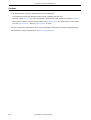
If a project file generated by the other NEC Electronics tools (debugger, etc.) is to be opened, refer to the "5. 1. 7 Opening a workspace".
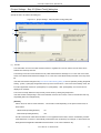
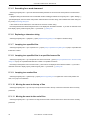
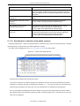
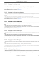
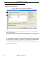
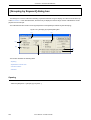
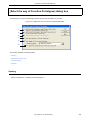
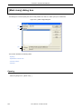
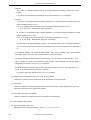
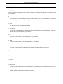
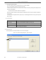
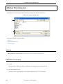
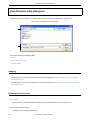
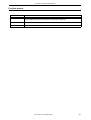
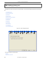
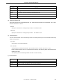
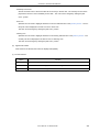
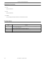
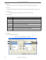
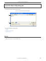
5. 1. 6 Creating a new workspace
Selecting the [File] menu -> [New Workspace...] creates a new workspace.
To create a new workspace and its project, the following wizard-format dialog boxes are displayed. Enter/select the
necessary information in each dialog box and click the [Next>] button to proceed.
- [New Workspace - Step 1/9 [Workspace Information]] dialog box
- [New Workspace - Step 2/9 [Select Tools]] dialog box
- [New Workspace - Step 3/9 [Select Real-Time OS]] dialog box
- [New Workspace - Step 4/9 [Startup File]] dialog box
- [New Workspace - Step 5/9 [Register Mode]] dialog box
- [New Workspace - Step 6/9 [LinkDirective File]] dialog box
- [New Workspace - Step 7/9 [Setup Source Files]] dialog box
- [New Workspace - Step 8/9 [Select Debugger]] dialog box
- [New Workspace - Step 9/9 [Confirmation]] dialog box
Clicking the [Finish] button in the dialog box at the last step ([New Workspace - Step 9/9 [Confirmation]] dialog box)
causes a make file to be created automatically. Refer to the "5. 6. 10 Exporting a make file" for details of make file creation.
The dialog boxes to be displayed differ depending on the selection. The wizard flow of each selection is shown below:
38
User’s Manual U17990EJ1V0UM
CHAPTER 5 METHOD OF OPERATION
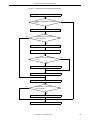
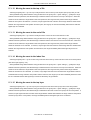
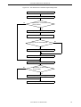
Figure 5-1 Wizard Flow for Creating New Workspace
Step 1/9 (Workspace Information)
Check to "Create Blank Workspace"
option
Yes
No
Step 2/9 (Select Tools)
No
Specification of V850 series
and non-library
Yes
Step 3/9 (Select Real-Time OS)
Step 4/9 (Startup File)
Check to "Use the Sample file"
option
No
Yes
Step 5/9 (Register Mode)
Step 6/9 (Link Directive File)
Step 7/9 (Setup Source Files)
No
Specification of V850 series
and non-library
Yes
Step 8/9 (Select Debugger)
Step 9/9 (Confirmation)
User’s Manual U17990EJ1V0UM
39
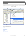
CHAPTER 5 METHOD OF OPERATION
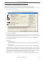
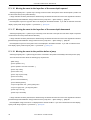
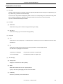
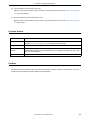
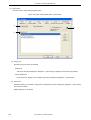
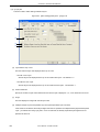
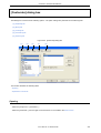
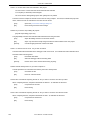
The configuration of a typical dialog box is described below.
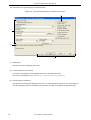
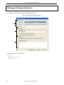
Figure 5-2 Wizard-Format Dialog Box for Creating ANew Workspace
(3)
(1)
(2)
(4)
(1) Setting items
The items to be set are displayed in this area.
(2) Function description and cautions
The function of the dialog box and applicable cautions are described in this area.
This area is not displayed in the [New Workspace - Step 9/9 [Confirmation]] dialog box.
(3) Current position of wizard flow
The whole flow of the wizard is displayed in this area. î>>î mark signifies the position of the current dialog box.
If the flow changes according to the selection of information, the steps to be skipped are displayed in gray.
40
User’s Manual U17990EJ1V0UM
CHAPTER 5 METHOD OF OPERATION
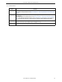
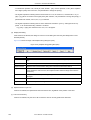
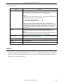
(4) Function buttons
Button
Function
<Back
Returns to the previous wizard step.
This button is always disabled in the [New Workspace - Step 1/9 [Workspace Information]] dialog box.
Next>
Opens the next step dialog box. (The next step dialog box to be opened differs depending on
the selection.)
This button appears as [Finish] button in the [New Workspace - Step 9/9 [Confirmation]] dialog
box. Terminates this wizard for creating a new workspace, and generates a new workspace
file and a project file belonging to that workspace, according to the displayed information.
Cancel
Stops the operation for creating a new workspace file, and returns to its previous status (in
which the previously read workspace file is available for use).
Help
Opens the help for this dialog box.
User’s Manual U17990EJ1V0UM
41
CHAPTER 5 METHOD OF OPERATION
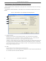
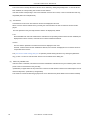
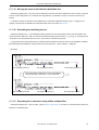
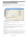
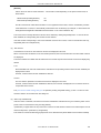
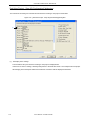
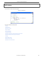
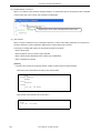
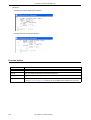
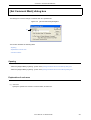
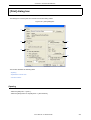
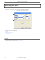
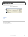
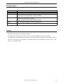
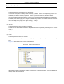
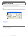
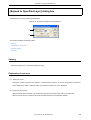
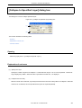
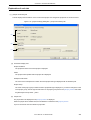
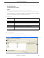
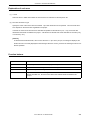
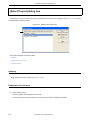
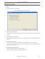
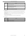
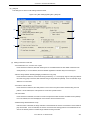
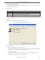
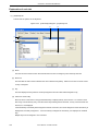
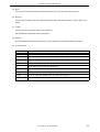
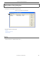
[New Workspace - Step 1/9 [Workspace Information]] dialog box
Specify a workspace file name, a folder position, a project group name, and the series and device name of the target
device to be used.
The specification of the item marked with "*" in this dialog box can not be omitted (i.e. the [Next>] button can not be
selected).
Figure 5-3 [New Workspace - Step 1/9 [Workspace Information]] Dialog Box
(1)
(2)
(3)
(4)
(1) Workspace File Name
Specify the name of the file to save the workspace information. Up to 255 characters can be specified.
The file extension is ".prw". If the extension is omitted, it is automatically set to ".prw". The file name which
changed the workspace file extension "prw" to "prj" is assigned as the project file name.
In addition, if a existing workspace file name is specified, the message dialog box is displayed after the [Next>] button is clicked, and then the existing workspace file will be renamed as backup file (e.g. test.prw -> test.prw.bak).
If [Create Blank Workspace] is selected, only a workspace is created. In this case, [Project Group Name], [Series
Name], and [Device Name] become invalid.
(2) Folder
Specify the folder in which the workspace file and project file are stored.
Selecting the [Browse...] button opens the [Browse for Folder] dialog box in which to specify the project folder position. The folder in which PM+.exe exists is default folder.
42
User’s Manual U17990EJ1V0UM
CHAPTER 5 METHOD OF OPERATION
(3) Project Group Name
Specify the name of the project group to be displayed on the [Project] window. Up to 127 characters can be specified.
If the specification of this area is omitted, the name of the project group displayed on the [Project] window is the
same as the name of the workspace file.
In addition, the project title of the project newly created by this wizard is assigned the name of the project group
specified with this area. If you wish to change a project title, select the [Edit Project Title...] menu by clicking the
mouse right button on the target project title in the [Project] window.
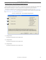
(4) Series Name and Device Name
Select the item to be created and the device file to be used from the drop-down list.
Clicking the [Device Install] button starts the device file installer to register the new device file.
User’s Manual U17990EJ1V0UM
43
CHAPTER 5 METHOD OF OPERATION
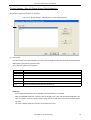
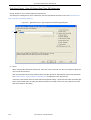
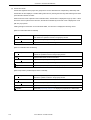
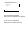
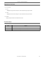
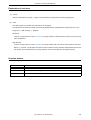
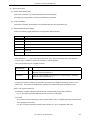
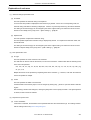
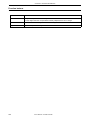
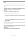
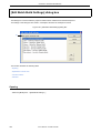
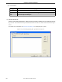
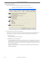
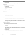
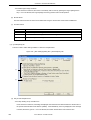
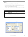
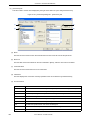
[New Workspace - Step 2/9 [Select Tools]] dialog box
Specify the tool to be used in this dialog box.
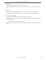
Figure 5-4 [New Workspace - Step 2/9 [Select Tools]] Dialog Box
(1)
(2)
(1) Tool Set
The combination of tools to be used and their versions is regarded as a tool set, and the tool set name can be
selected from the drop-down list.
The existing tool set and recommended tool set ("V850 Series Software Package Vx.xx" in the case of the V850
Series, and "78K0R Series Software Package Vx.xx" in the case of the 78K0R Series) are listed on the drop-down
list.
If the tool set has been changed in the [Tool Version Detail Setting] dialog box opened by clicking the [Detail Setting...] button, "(Changed)" is appended at the top of the tool set name. If the tool set name already exists, the indication appended varies from "(Changed01)" to "(Changed99)". After "(Changed99)", the tool set name is displayed
as "UserSet". The tool set currently selected in this list can be saved by clicking the [Save] button.
If the tool set files corresponding to the tool set selected on this list do not exist, or the tool set files are read-only,
the [Save] button is invalid (dimmed).
44
User’s Manual U17990EJ1V0UM
CHAPTER 5 METHOD OF OPERATION
[Remark]
A file is saved as "tool-set-name.extension". The extension varies depending on the product series used, as
shown below.
78K0R Series (including libraries):
t0r
V850 Series (including libraries):
t85
The file is saved under "NEC Electronics\PM+" in the "Application Data" folder, which is accessible by all users.
If this folder does not exist, it is automatically created when PM+ is started up (for example, "C:\Documents and
Settings\All Users\Application Data\NEC Electronics\PM+" in the case of Windows XP).
The tool set name currently selected on this list can be deleted by clicking the [Delete] button. If the tool set has
been installed, the corresponding tool set files are also deleted.
If the tool set files corresponding to the tool set selected on this list do not exist, or the tool set files are read-only,
the [Delete] button is invalid (dimmed).
(2) Tool Versions
Combinations of tools to be used and their versions are displayed in this area.
When a tool set name is selected on the [Tool Set] drop-down list, the tools included in the tool set and their versions are displayed.
The tools included in the default tool set selected on the Tool Set drop-down list and their versions are displayed by
default.
Tool:
All the installed tools and tools included in the selected tool set are displayed in this area.
Version:
The tool versions specified in the selected tool set are displayed in this area.
However, "Unused" is displayed for a tool whose version is not specified in the tool set.
The [Tool Version Detail Setting] dialog box is opened by clicking the [Detail Setting...] button. Tools to be used
and their versions can be selected in this dialog box.
(3) Select only Installed Tools
If this item is selected, tools that have not been installed are excluded from the "Tool Versions" list box which
corres ponds to the tool set selected in the Tool Set area (default).
"(Selected01)" is appended to the top of the name of the tool set with which this check box is selected (if the tool
set name actually exists, "(Selected0n)" is appended).
This check box cannot be selected (grayed) if there are no dimmed tools (all the listed tools have been installed).
User’s Manual U17990EJ1V0UM
45
CHAPTER 5 METHOD OF OPERATION
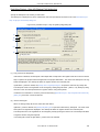
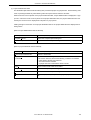
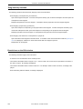
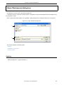
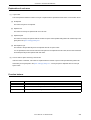
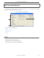
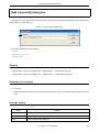
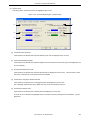
[New Workspace - Step 3/9 [Select Real-Time OS]] dialog box
Specify whether or not to use NEC Electronics real-time OS.
This dialog box is displayed only when "V850 Series" has been specified as the series name in the [New Workspace Step 1/9 [Workspace Information]] dialog box.
Figure 5-5 [New Workspace - Step 3/9 [Select Real-Time OS]] Dialog Box
(1)
(1) RTOS
When using the NEC Electronics real-time OS, select "the name of real-time OS", when not using that, select "Not
use" from the drop-down list.
"Not use" and all the names of the real-time OSs for the NEC Electronics V850 Series that have been specified in
the [New Workspace - Step 2/9 [Select Tools]] dialog box are displayed on the drop-down list.
If the name of the real-time OS to be used is selected, the [RTOS Settings...] button becomes valid, and clicking
this button opens the dialog box for setting the selected real-time OS in detail. Refer to the user's manual of the
real-time OS for details on the setting.
46
User’s Manual U17990EJ1V0UM
CHAPTER 5 METHOD OF OPERATION
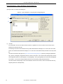
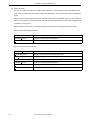
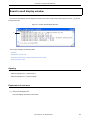
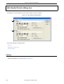
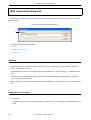
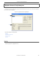
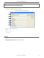
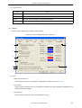
[New Workspace - Step 4/9 [Startup File]] dialog box
Specify a startup file.
This dialog box is displayed only when "V850 Series" has been specified as the series name in the [New Workspace Step 1/9 [Workspace Information]] dialog box.
Figure 5-6 [New Workspace - Step 4/9 [Startup File]] Dialog Box
(1)
(2)
(3)
(4)
(5)
(1) Copy and Use the Sample file
If this button is selected, the startup file of the sample that corresponds to the register mode set in the next wizard
step is copied to the project folder and registered to the project-related files. The name of the startup file to be registered is displayed in The Startup File Name to register edit box as an absolute path.
The startup file name to be registered can be changed by clicking the [File Name...] button, or by directly inputting
the name in the "The Startup File Name to register" edit box using the keyboard.
If real-time OS is selected for use in the previous wizard step ([New Workspace - Step 3/9 [Select Real-Time OS]]
dialog box), this button cannot be selected.
User’s Manual U17990EJ1V0UM
47
CHAPTER 5 METHOD OF OPERATION
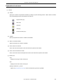
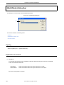
(2) Use the Existing file
When an existing startup file is used, select this radio button.
If [Browse...] button is clicked, the [Startup File] dialog box is opened to select the any startup file. The name of the
startup file to be registered is displayed in The Startup File Name to register edit box as an absolute path.
The startup file name to be registered can be changed by directly inputting the name in the "The Startup File Name
to register" edit box using the keyboard.
If an existing file is used, the [File Name...] button cannot be selected.
(3) Copy and Use the Existing file
When an existing startup file is copied and used, select this radio button. Specify the startup file name to be the
copy source and the startup file name to be the copy destination.
If [Browse...] button is clicked, the [Copy Startup File from] dialog box is opened to select the any startup file. The
name of the startup file to be the copy source is displayed in the Copy from edit box as an absolute path. Alternatively, the file name to be specified can also be input in the Copy from edit box either as an absolute path or a relative path using the keyboard.
The startup file name to be registered can be changed by clicking the [File Name...] button, or by directly inputting
the name in the "The Startup File Name to register" edit box using the keyboard.
(4) Do Not specify now
When no startup file is specified now, select this radio button.
In this case, a startup file can be specified by selecting the project-related file folder on the [Project] window and
then selecting [Add Project Related files...] using the right mouse button, or selecting the [Tool] menu -> [Linker
Options...].
(5) The Startup File Name to register
Specify the name of the startup file to be registered.
If [File Name...] button is clicked, the [Startup File to register] dialog box is opened to select the any startup file.
Alternatively, the file name to be specified can also be input in The Startup File Name to register edit box edit box
either as an absolute path or a relative path using the keyboard.
[Caution]
If after selecting "Do Not specify now" for the startup file and registering the source file in the [New Workspace - Step
7/9 [Setup Source Files]] dialog box, and then returning to this dialog box and specifying the source file registered in
the [New Workspace - Step 7/9 [Setup Source Files]] dialog box as the startup file, and ending the wizard as is, the
following linker option setting message is displayed, and the startup file is registered to both the source file and
project-related files.
"Startup file specification is illegal."
Delete the startup file registered to the source file.
48
User’s Manual U17990EJ1V0UM
CHAPTER 5 METHOD OF OPERATION
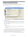
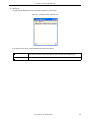
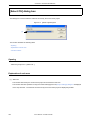
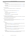
[New Workspace - Step 5/9 [Register Mode]] dialog box
Specify the register mode option for the compiler. The sample file of the startup file corresponding to the register mode
which is selected in this dialog box is copied to the project folder, and registered to the project-related files.
This dialog box is displayed only when "V850 Series" has been specified as the series name in the [New Workspace Step 1/9 [Workspace Information]] dialog box and "Copy and Use the Sample file" has been specified in the previous wizard step ([New Workspace - Step 4/9 [Startup File]] dialog box).
Figure 5-7 [New Workspace - Step 5/9 [Register Mode]] Dialog Box
(1)
(2)
(3)
(1) 22-Register Mode
The startup file is determined as the 22-register mode.
(2) 26-Register Mode
The startup file is determined as the 26-register mode.
(3) 32-Register Mode
The startup file is determined as the 32-register mode.
User’s Manual U17990EJ1V0UM
49
CHAPTER 5 METHOD OF OPERATION
[Caution]
If the register mode of the compiler option is changed after a new workspace is created, the quasi directive indicating the register mode in the startup file may indicate a different mode from the register mode of the other
source files. Therefore, execute the relevant processing/measure from those shown below:
- Modify the quasi directive that indicates the register mode in the startup file as follows:
*) In 22-register mode
#-----------------------------#
register mode
#------------------------------
*) In 26-register mode
#-----------------------------#
register mode
#------------------------------
*) In 32-register mode
Delete ".option reg_mode " line.
- Ignore the following warning displayed at linking.
Id850: W4608: input file have different register modes, use "-rc" option for more information.
50
User’s Manual U17990EJ1V0UM
CHAPTER 5 METHOD OF OPERATION
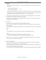
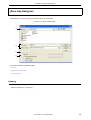
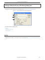
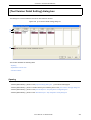
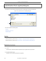
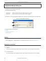
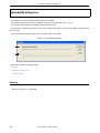
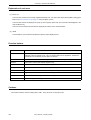
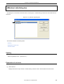
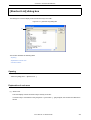
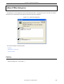
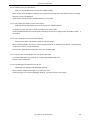
[New Workspace - Step 6/9 [LinkDirective File]] dialog box
Specify a link directive file. The specified link directive file is registered to the project-related files.
This dialog box is displayed only when "V850 Series" has been specified as the series name in the [New Workspace Step 1/9 [Workspace Information]] dialog box.
Figure 5-8 [New Workspace - Step 6/9 [LinkDirective File]] Dialog Box
(1)
(2)
(3)
(4)
(5)
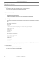
(1) Create and Use the Sample file
If this radio button is selected, a sample link directive file is created in the project folder in accordance with the
selection in [Memory Usage] area and the selection of the OS in the [New Workspace - Step 3/9 [Select Real-Time
OS]] dialog box. The link directive file is created under the name "project file name.dir" and registered to the
project-related files automatically.
Memory Usage:
- Use Internal memory only
The external ROM is mapped to the internal ROM area when the compiler is used in ROMless mode.
- Use External memory
The TEXT sections are mapped to the internal memory, and the DATA sections to the external memory.
The link directive file that is created is registered to the project-related files automatically. The name of the link
directive file to be registered is displayed in The Link Directive File Name to register edit box as an absolute path.
The link directive file name to be registered can be changed by clicking the [File Name...] button, or by directly
inputting the name in the "The Link Directive File Name to register" edit box using the keyboard.
Refer to "APPENDIX A SAMPLE LINK DIRECTIVE FILE" for the detail of the link directive file to be created.
User’s Manual U17990EJ1V0UM
51
CHAPTER 5 METHOD OF OPERATION
[Caution]
The link directive file that is created must be customized in accordance with the target specification or userdefined sections.
(2) Use the Existing file
When an existing link directive file is used, select this radio button.
If [Browse...] button is clicked, the [Link Directive File] dialog box is opened to select the any startup file. The name
of the link directive file to be registered is displayed in The Link Directive File Name to register edit box as an absolute path.
The link directive file name to be registered can be changed by directly inputting the name in the "The Link Directive
File Name to register" edit box using the keyboard.
If an existing link directive file is used, the [File Name...] button cannot be selected.
(3) Copy and Use the Existing file
When an existing link directive file is copied and used, select this radio button. Specify the link directive file name
to be the copy source and the link directive file name to be the copy destination.
If [Browse...] button is clicked, the [Copy Link Directive File from] dialog box is opened to select the any startup file.
The name of the link directive file to be the copy source is displayed in the Copy from edit box as an absolute path.
Alternatively, the file name to be specified can also be input in the Copy from edit box either as an absolute path or
a relative path using the keyboard.
The link directive file name to be registered can be changed by clicking the [File Name...] button, or by directly
inputting the name in the "The Link Directive File Name to register" edit box using the keyboard.
(4) Do Not specify now
When no link directive file is specified, select this radio button.
A link directive file can be specified by selecting a project-related file folder on the [Project] window and then selecting [Add Project Related files...] using the right mouse button, or selecting the [Tool] menu -> [Linker Options...]
after exiting the wizard.
(5) The Link Directive File Name to register
Specify the name of the link directive file to be registered.
If [File Name...] button is clicked, the [Link Directive File to register] dialog box is opened to select the any startup
file. Alternatively, the file name to be specified can also be input in The Link Directive File Name to register edit box
edit box either as an absolute path or a relative path using the keyboard.
52
User’s Manual U17990EJ1V0UM
CHAPTER 5 METHOD OF OPERATION
[New Workspace - Step 7/9 [Setup Source Files]] dialog box
Specify the name of the source file to be registered into the project.
It is possible to proceed to the next step by clicking the [Next>] button even if no source files are specified in this dialog
box. In this case, source files can be registered into the project by specifying with the [Project Settings] dialog box or dragging and dropping the source files to be registered onto the [Project] window.
Figure 5-9 [New Workspace - Step 7/9 [Setup Source Files]] Dialog Box
(1)
(1) Source File Name
The names of the source files to be registered into the project are displayed in the source file list box.
The source files are registered to the project file in the order currently shown in this list box. In addition, the build
processing are performed in the registered order.
[Cautions]
- If the compiler and assembler are not installed, source file addition is not possible.
- If, after a source file is added, the series name is changed by returning to the [New Workspace - Step 1/9
[Workspace Information]] dialog box, files among the previously added file other than those with extensions
corresponding to the series after the change are also displayed in the source file list box. In this case, delete
these source files.
User’s Manual U17990EJ1V0UM
53
CHAPTER 5 METHOD OF OPERATION
Button
54
Function
Add...
Opens the [Add Source Files] dialog box to specify the source code files to be registered to
the project. Up to 2048 source files can be registered per project. The extension of source
code file differs depending on the series name registered to the project.
Remove
Removes the selected file from the source file list box. By selecting a file name while holding
down the SHIFT or CTRL key, multiple source file names can be selected at once. The
names of the removed files are not registered to the project.
If no source file is selected or listed in the source file list box, this button can not be selected.
Remove All
Removes all the source files from the source file list box. The names of the removed files
are not registered to the project.
If no source file is selected or listed in the source file list box, this button can not be selected.
Up
Moves the selected file up within the source file list box.
Down
Moves the selected file down within the source file list box.
User’s Manual U17990EJ1V0UM
CHAPTER 5 METHOD OF OPERATION
[New Workspace - Step 8/9 [Select Debugger]] dialog box
Select the debugger which debug the project to be created newly.
The specification of the item marked with "*" in this dialog box can not be omitted (i.e. the [Next>] button can not be
selected). The debugger specified with this dialog box can be changed after exiting this wizard.
Figure 5-10 [New Workspace - Step 8/9 [Select Debugger]] Dialog Box
(1)
(2)
(3)
(1) Debugger
Select the debugger to be used from the drop-down list. All the NEC Electronics debuggers that have been
installed are displayed in the drop-down list together with the corresponding series name.
When a debugger is selected from this list, the file name of the debugger is displayed in the [File Name] text box
and the selected debugger will start up automatically when a debug operation is executed.
If you wish to change the debugger to be used after exiting the wizard, select the [Tool] menu -> [Debugger Setting...].
(2) File name
The file name of the debugger to be used for debugging is displayed. When the debugger is selected by the
[Debugger] drop-down list, that file name is displayed with the path automatically.
This text box cannot be edited.
(3) Option
Specify the options for when starting up the debugger.
If this specification is omitted, no option is specified for starting up the debugger.
User’s Manual U17990EJ1V0UM
55
CHAPTER 5 METHOD OF OPERATION
[New Workspace - Step 9/9 [Confirmation]] dialog box
The contents of the specification are confirmed and the wizard for creating a new workspace is terminated.
Figure 5-11 [New Workspace - Step 9/9 [Confirmation]] Dialog Box
(1)
(1) The display of the settings
The various information specified with this wizard for creating a new workspace is displayed.
If the contents shown in this dialog box are correct, click the [Finish] button to terminate this wizard. Then PM+
generates a new workspace file and a project file belonging to that workspace, according to the information displayed.
56
User’s Manual U17990EJ1V0UM
CHAPTER 5 METHOD OF OPERATION
5. 1. 7 Opening a workspace
Selecting [File] menu -> [Open Workspace...] or moving the workspace file using a drag-and-drop operation opens a
workspace.
Selecting the [File] menu -> [Open Workspace...] displays the [Open Workspace] dialog box and opens the selected
workspace file (*.prw) on the [Project] window. At this time, closes the currently opened workspace file and project file. If
a project file (*.prj), rather than a workspace file, is specified, a message is displayed, after which the prw file corresponding to prj is opened. At this time, the project file (*.prj) of PM (V3.xx) format can also be specified in this dialog box. (Refer
to the "5. 1. 5 Opening a project file generated by the previous version".)
If a workspace file is is dragged to the main frame, Edit window, Search result display window, [OutPut] window, and
[Project] window, opens the workspace file that was dropped. At this time, closes the currently opened workspace file. If
a project file (*.prj), rather than a workspace file, is moved using a drag-and-drop operation, a prw file corresponding to prj
is opened.
If an attempt is made to open a project file created by another NEC Electronics tool (debugger or simulator), a message
is displayed, after which the following wizard-format dialog boxes for updating the project information for PM+ are opened.
Enter/select the necessary information in each dialog box and click the [Next>] button to proceed.
- [Project Settings - Step 1/3 [Project Information]] dialog box
- [Project Settings - Step 2/3 [Select Tools]] dialog box
- [Project Settings - Step 3/3 [Setup Source Files]] dialog box
User’s Manual U17990EJ1V0UM
57
CHAPTER 5 METHOD OF OPERATION
The configuration of a typical dialog box is described below.
Figure 5-12 Wizard-Format Dialog Box for Updating The Project Information
(1)
(2)
(1) Setting items
The items to be set are displayed in this area.
(2) Function buttons
Button
58
Function
<Back
Returns to the previous wizard.
This button is always disabled in the [Project Settings - Step 1/3 [Project Information]] dialog
box.
Next>
Opens the next wizard.
This button appears as [Finish] button in the [Project Settings - Step 3/3 [Setup Source
Files]] dialog box. In this case, sets the project information and the source file information
into the project file and terminates this wizard.
Cancel
Does not enable the specified items, and closes this dialog box.
Help
Opens the help for this dialog box.
User’s Manual U17990EJ1V0UM
CHAPTER 5 METHOD OF OPERATION
[Project Settings - Step 1/3 [Project Information]] dialog box
Confirms the project information and modify the project title and the series and device name of the target device to be
used.
Figure 5-13 [Project Settings - Step 1/3 [Project Information]] Dialog Box
(1)
(2)
(3)
(1) Information display area
Project File Name:
The name of the project file is displayed.
Folder:
The project folder specified in the project file is displayed.
Workspace File Name:
The name of the workspace file to which the project belongs is displayed with an absolute path.
The file name is automatically determined as project file name + extension (*.prw).
Project Group:
The name of the project group to which the project belongs is displayed.
If you wish to change the name of the project group, after this wizard terminates, click the name of that project
group with the right mouse button in the [Project] window and select the [Edit Project Group Name...] menu.
User’s Manual U17990EJ1V0UM
59
CHAPTER 5 METHOD OF OPERATION
(2) Project Title
The project title to be displayed in the [Project] window is displayed.
If the project title is modified here, the modification is reflected in the [Project] window.
Up to 127 characters can be entered for a project title.
(3) Series Name and Device Name
The series and device name of the target device to be used are displayed.
They can be changed by selecting from the drop-down lists.
If the device file for the device to be used has not been installed, the following message will be displayed under the
device name displayed.
"The device file that has been selected is not registered."
When this message is displayed, clicking the [Device Install] button starts the device file installer to register the new
device file.
If multiple projects are registered into the project group, or if the debugger/simulator is running, these drop-down
lists are invalid.
60
User’s Manual U17990EJ1V0UM
CHAPTER 5 METHOD OF OPERATION
[Project Settings - Step 2/3 [Select Tools]] dialog box
Specify the tool to be used in this dialog box.
Figure 5-14 [Project Settings - Step 2/3 [Select Tools]] Dialog Box
(1)
(2)
(3)
(1) Tool Set
The combination of tools to be used and their versions is regarded as a tool set, and the tool set name can be
selected from the drop-down list.
The existing tool set and recommended tool set ("V850 Series Software Package Vx.xx" in the case of the V850
Series, and "78K0R Series Software Package Vx.xx" in the case of the 78K0R Series) are listed on the drop-down
list.
If the tool set has been changed in the [Tool Version Detail Setting] dialog box that is opened by clicking the [Detail
Setting...] button, "(Changed)" is appended at the top of the tool set name. If the tool set name already exists, the
ind ication appended varies from "(Changed01)" to "(Changed99)". After "(Changed99)", the tool set name is
displayed as "UserSet".
The tool set currently selected in the [Tool Set] can be saved by clicking the [Save] button.
If the tool set files corresponding to the tool set selected on this list do not exist, or the tool set files are read-only,
the [Delete] button is invalid (dimmed).
[Remark]
A file is saved as "tool-set-name.extension". The extension varies depending on the product series used, as
shown below.
78K0R Series (including libraries):
t0r
V850 Series (including libraries):
t85
The file is saved under "NEC Electronics\PM+" in the "Application Data" folder, which is accessible by all users.
If this folder does not exist, it is automatically created when PM+ is started up (for example, "C:\Documents and
Settings\All Users\Application Data\NEC Electronics\PM+" in the case of Windows XP).
User’s Manual U17990EJ1V0UM
61
CHAPTER 5 METHOD OF OPERATION
The tool set name currently selected on this list can be deleted by clicking the [Delete] button. If the tool set has
been installed, the corresponding tool set files are also deleted.
If the tool set files corresponding to the tool set selected on this list do not exist, or the tool set files are read-only,
the [Delete] button is invalid (dimmed).
(2) Tool versions
Combinations of tools to be used and their versions are displayed in this area.
When a tool set name is selected in the [Tool Set], the tools included in the tool set and their versions are displayed.
The tools specified in the [Tool Set] and their versions are displayed by default.
Tool:
All the installed tools and tools included in the selected tool set (including tools that have not been installed) are
displayed in this area. However, tools that have not been installed are dimmed.
Version:
The tool versions specified in the selected tool set are displayed in this area.
However, tools that have not been installed are dimmed, and "Unused" is displayed for a tool whose version is
not specified in the tool set.
The [Tool Version Detail Setting] dialog box is opened by double-clicking this area or by clicking the [Detail Setting...] button. Tools to be used and their versions can be selected in this dialog box.
(3)
Select only Installed Tools
If this check box is selected, tools that have not been installed are excluded from the [Tool Versions] which corres
ponds to the tool set selected in the [Tool Set].
"(Selected01)" is appended to the top of the name of the tool set with which this check box is selected (if the tool set
name actually exists, "(Selected nn)" is appended).
This check box cannot be selected (grayed) if there are no dimmed tools (all the listed tools have been installed).
62
User’s Manual U17990EJ1V0UM
CHAPTER 5 METHOD OF OPERATION
[Project Settings - Step 3/3 [Setup Source Files]] dialog box
Specifies the source file information on the project.
Figure 5-15 [Project Settings - Step 3/3 [Setup Source Files]] Dialog Box
(1)
(1) Source Files
The names of the source files specified by the project file are displayed in the order the build processing with the
relative path on the basis of the project folder.
Up to 2048 source files can be registered.
Button
Function
Add...
Opens [Add Source Files] dialog box to add the source file to the project.
Remove
Removes the selected source file from the list.
Remove All
Removes all the source files from the list.
Up
Moves the selected source file up within the list.
Down
Moves the selected source file down within the list.
[Cautions]
- If the compiler and assembler are not installed, source file addition is not possible.
- Make is assembled/compiled in accordance with the program type, in the order the files are displayed in the
list of source files. The path of project folder is being used for the path name of the source file when executing make.
The order of linkage depends on the linker in the series to be used.
User’s Manual U17990EJ1V0UM
63
CHAPTER 5 METHOD OF OPERATION
5. 1. 8 Saving a workspace
Selecting the [File] menu -> [Save Workspace] saves the currently opened workspace.
The information of the opened workspace and the project(s) is saved into the current file. (by overwriting)
5. 1. 9 Closing a workspace
Selecting the [File] -> [Close Workspace] closes all the currently opened windows. At this time, you can select whether
all the Edit window are to be closed. After the all windows are closed, "No Workspace" will appear on the [File] tag in the
[Project] window.
5. 1. 10 Saving a file by overwriting
Selecting the [File] menu -> [Save] saves an IDL file or and a source file are saved into the each current file (by overwriting). All the current file information including such as the layer information and the location of the caret in the Edit window
is saved into the IDL file.
By specifying the [Layer Indent] area ([Tool] menu -> [PM+ Settings...] - [Source File by idl file] tab), the indent by layer
can be replaced with the Tab code or a single-byte space.
If the following files are active, the [Save As] dialog box is displayed to specify the name of the file.
- A newly created Edit window
A default file name is created based on the contents of the first line in the Edit window.
- A Search result display window
A default file name is created based on the contents of the first line in the Edit window.
- An IDL backup file opened by selecting the [Open] menu or the history of the file.
A default file name is "backup file name.idl".
- An Edit window in which multiple files were read.
A default file name is created based on the contents of the first line in the Edit window.
- A file saved automatically
A default file name is created based on the contents of the first line in the Edit window.
- A newly created source file
A default file name is created based on the contents of the first layer line of each file in the Edit window.
5. 1. 11 Saving a file with a new name
Selecting the [File] menu -> [Save as...] opens the [Save As] dialog box to assign a name to the file being edited and
save it. In addition, the indent by the layer and the setting of the Tab can be specified with the [Save Source Files Options]
dialog box.
64
User’s Manual U17990EJ1V0UM
CHAPTER 5 METHOD OF OPERATION
5. 1. 12 Saving all files
Selecting the [File] menu -> [Save All] saves all of the files currently open in the Edit window by overwriting. The contents of the Edit window including those that have not been modified are also saved, however, the contents of the Edit window, [OutPut] window and Search result display window that have the read-only attribute are not saved.
Note that [Save All (Changed files Only)] menu item is not displayed in the default condition. If you wish to make this
menu item display, specify it with the [Tool] menu -> [Customize...] - [Menu] tab.
5. 1. 13 Saving all files (Changed files only)
By selecting the [File] menu -> [Save All (Changed files Only)], the contents of all the Edit window currently opened are
saved by the same file name. However, the contents of the Edit window including those that have not been modified is not
saved.
Note that [Save All (Changed files Only)] menu item is not displayed in the default condition. If you wish to make this
menu item display, specify it with the [Tool] menu -> [Customize...] - [Menu] tab.
5. 1. 14 Saving and Closing all files
Selecting the [File] menu -> [Save and Close All] saves all of the files currently open in the Edit window and then closes
the windows. The [Project] window and the [OutPut] window are not closed.
Note that [Save and Close All] menu item is not displayed in the default condition. If you wish to make this menu item
display, specify it with the [Tool] menu -> [Customize...] - [Menu] tab.
5. 1. 15 Closing all windows
Selecting the [File] menu -> [Close All] closes all the Edit window currently open. If any of the contents have been
changed, a message for confirming whether the changes are to be saved is displayed. The [Project] window and the [OutPut] window are not closed.
Note that [Close All] menu item is not displayed in the default condition. If you wish to make this menu item display,
specify it with the [Tool] menu -> [Customize...] - [Menu] tab.
5. 1. 16 Closing all windows without saving
Selecting the [File] menu -> [Destroy All] closes all the Edit window currently open without saving. The [OutPut] window
and the [Project] window are not closed.
5. 1. 17 Changing a source file name
Selecting the [File] menu -> [Change Source File Name...] opens the [Change Source File Names] dialog box in which
the name of the source file can be changed.
User’s Manual U17990EJ1V0UM
65
CHAPTER 5 METHOD OF OPERATION
5. 1. 18 Saving all source files
Selecting the [File] menu -> [Save All Source Files] saves all the source files by overwriting regardless of whether the
contents are modified or not.
5. 1. 19 Checking printing status
Selecting the [File] menu -> [Print Preview] displays the printing status of the active Edit window in the condition set in
the [Print] dialog box.
The following functions are supported on the print preview window:
[Print]
Displays the [Print] dialog box.
[Next Page]
Displays the next screen.
[Prev Page]
Displays the previous screen.
[One Page/Two Page ]
Toggles the display mode between one-page or two-page.
[Zoom In]
Expands the display in two steps.
[Zoom Out]
Reduces the display in two steps.
[Close]
Closes the print preview window.
5. 1. 20 Printing
Selecting the [File] menu -> [Print...] opens the [Print] dialog box to print the contents of the active Edit window.
5. 1. 21 Printing directly
Selecting the [File] menu -> [Print Direct] prints the contents of the active Edit window without opening the [Print] dialog
box.
5. 1. 22 History of files
The bottom of the [File] menu displays the names of the ten most recently edited/saved files. Selecting any one of them
causes the Edit window for that file to open.
5. 1. 23 History of workspaces
The bottom of the [File] menu displays the names of the ten most recently opened workspace files or project files.
5. 1. 24 Exiting PM+
To exit the PM+, select [File] menu -> [Exit PM+] or the [Close] button. For any window that has been edited, a message for confirming whether to save the changes is displayed, then the PM+ is exited.
66
User’s Manual U17990EJ1V0UM
CHAPTER 5 METHOD OF OPERATION
5. 2 Edit Functions
Operations related to editing files in PM+ are shown below.
The operations described in this section are performed using the [Edit] menu in the Main window.
- Canceling an edit operation
- Canceling an [Undo] operation
- Cutting off character strings
- Copying character strings
- Cutting off character strings (Cut for Append)
- Copying character strings (Copy for Append)
- Copying character strings as a screen image
- Inserting the contents of clipboard
- Inserting the contents of clipboard with specified format
- Deleting character strings
- Deleting a word
- Deleting characters to the end of a word
- Deleting a line
- Deleting character strings to the top of line
- Deleting character strings to the end of line
- Selecting a word at the caret
- Selecting a word to the left of the caret
- Selecting a word to the right of the caret
- Selecting a range to the top of line
- Selecting a range to the end of line
- Selecting entire contents
- Grouping by keyword
- Restoring color of grouping line
- Creating function prototypes
- Inserting a new object
- Setting links for objects
- Object
User’s Manual U17990EJ1V0UM
67
CHAPTER 5 METHOD OF OPERATION
5. 2. 1 Canceling an edit operation
Selecting the [Edit] menu -> [Undo] cancels the effect of an edit operation and restores the previous state. Up to 1024
edit operations can be undone.
[Undo] is effective for the following edit operations:
- Entry of characters into the Edit window. (The key input is canceled for each one character including the TAB, DEL,
BS and ENTER key.)
- [File] -> [Insert file...]
- [Edit] -> [Cut]
- [Edit] -> [Paste]
- [Edit] -> [Paste Special...]
- [Edit] -> [Delete]
- [Edit] -> [Delete the Line]
- [Edit] -> [Insert New Object...]
- Replacement of a character string using [Find] -> [Replace...] (except [Replace All])
- Copying of lines by dragging of mouse
- Movement of lines by dragging of mouse
- Insertion of a tab character at the beginning of a line
- Deletion of a tab character at the beginning of a line
- [Layer] -> [Promote]
- [Layer] -> [Demote]
5. 2. 2 Canceling an [Undo] operation
Selecting the [Edit] menu -> [Redo] cancels the effect of an [Undo] operation and restores the previous state. Up to
1024 edit operations can be redone.
[Redo] is effective for the following edit operations:
- Entry of characters into the Edit window. (The key input is canceled for each one character including the TAB, DEL,
BS and ENTER key.)
- [File] -> [Insert file...]
- [Edit] -> [Cut]
- [Edit] -> [Paste]
- [Edit] -> [Paste Special...]
- [Edit] -> [Delete]
- [Edit] -> [Delete the Line]
- [Edit] -> [Insert New Object...]
- Replacement of a character string using [Find] -> [Replace...] (except [Replace All])
- Copying of lines by dragging of mouse
- Movement of lines by dragging of mouse
- Insertion of a tab character at the beginning of a line
68
User’s Manual U17990EJ1V0UM
CHAPTER 5 METHOD OF OPERATION
- Deletion of a tab character at the beginning of a line
- [Layer] -> [Promote]
- [Layer] -> [Demote]
5. 2. 3 Cutting off character strings
Selecting the [Edit] menu -> [Cut] sends the character string or lines selected with range selection to the clipboard and
deletes them from the Edit window.
If the lines selected with range selection have lower layers, the contents of the lower layer lines will also be sent to the
clipboard regardless of whether the layers are expanded or collapsed.
When a character string is cut, the caret position will not be changed. When lines are cut, the caret will be positioned to
the beginning of the line following the cut position. When the last line of a document is cut, the caret will be positioned to
the end of the new last line.
5. 2. 4 Copying character strings
Selecting the [Edit] menu -> [Copy] sends the character string or the lines selected with range selection to the clipboard.
If the lines selected with range selection have lower layers, the contents of the lower layer lines will also be sent to the
clipboard regardless of whether the layers are expanded or collapsed.
5. 2. 5 Cutting off character strings (Cut for Append)
Selecting the [Edit] menu -> [Cut for Append] adds the contents of the character strings or the lines selected with range
selection to the end of the clipboard and deletes them from the Edit window. This menu item dose not erase the previous
contents of the clipboard but instead appends the copy portion to the end of the contents of the clipboard.
If the lines selected with range selection have lower layers, the contents of the lower layer lines will also be sent to the
clipboard regardless of whether the layers are expanded or collapsed.
When a character string is cut, the caret position will not be changed. When lines are cut, the caret will be positioned to
the beginning of the line following the cut position. When the last line of a document is cut, the caret will be positioned to
the end of the new last line.
Note that [Cut for Append] menu item is not displayed in the default condition. If you wish to make this menu item display, specify it with the [Tool] menu -> [Customize...] - [Menu] tab.
5. 2. 6 Copying character strings (Copy for Append)
Selecting the [Edit] menu -> [Copy for Append] adds the contents of the character string or the lines selected with range
selection to the end of the clipboard. This menu item dose not erase the previous contents of the clipboard but instead
appends the copy portion to the end of the contents of the clipboard.
If the lines selected with range selection have lower layers, the contents of the lower layer lines will also be sent to the
clipboard regardless of whether the layers are expanded or collapsed.
Note that [Copy for Append] menu item is not displayed in the default condition. If you wish to make this menu item display, specify it with the [Tool] menu -> [Customize...] - [Menu] tab.
User’s Manual U17990EJ1V0UM
69
CHAPTER 5 METHOD OF OPERATION
5. 2. 7 Copying character strings as a screen image
Selecting the [Edit] menu -> [Image Copy] sends the character string or lines selected with range selection to the clipboard exactly as they are displayed on the screen (as a screen image).
When the contents of the lines are sent to the clipboard, no layer information is sent. Each time the layer is demoted by
one, a space or Tab code is written. The code to write can be specified with [Image Copy] on the [Tool] menu -> [PM+
Settings...] - [Edit] tab. Furthermore, the number of the indent characters can be specified with [Indent Characters] on the
same [Edit] tab.
If the lines selected with range selection have lower layers, the contents of the lower layer lines that have been collapsed will not be sent to the clipboard. Note that objects cannot be copied.
5. 2. 8 Inserting the contents of clipboard
Selecting the [Edit] menu -> [Paste] reads the contents of the clipboard and inserts them at the caret position. At this
time, the layer information is also inserted.
When a character string is pasted, the caret will move to the position following the character string in the default condition. If, however, [Don't Move Caret as Paste] is selected on the [Edit] tab on the [Option] menu - [PM+ Settings...], the
caret will not move.
When lines are pasted, they are inserted to the line above the caret position and the screen is redisplayed without moving of the caret position. If, however, the caret is positioned to the top line of the screen or if is not visible on the screen,
the screen is scrolled and redisplayed so that the caret is positioned to the middle of the screen.
If you perform [Paste] while performing range selection, the lines selected with range selection will be deleted and the
contents of the clipboard will be inserted to the position occupied by the lines selected with range selection. At this time,
the caret will be positioned to the top of the line following the inserted position. If, however, the caret is positioned to the
top line of the screen or if is not visible on the screen, the screen is scrolled and redisplayed so that the caret is positioned
to the middle of the screen.
If the first layer line having a lower layer is copied or cut off from the other file and pasted to the first layer of the IDL file
being edited, the source file name of the copy source is set as is. If the same source file name exists in the IDL file being
edited, however, the information of the source file name of the copy source will be deleted. If an attempt is made to save
the IDL file being edited in this case, a message prompting you to change the path of the source file name will be displayed, then if you will select [Yes] in response to this message, the [Change Source File Names] dialog box will be displayed. In this dialog box, specify the name of the source file to be created from the IDL file being edited.
5. 2. 9 Inserting the contents of clipboard with specified format
Selecting the [Edit] menu -> [Paste Special...] opens the Paste Special dialog box to select the format in which the contents of the clipboard are to be pasted, and then inserts the contents of the clipboard to the caret position. In the dialog
box, the processing depends on MFC (Microsoft Foundation Class).
70
User’s Manual U17990EJ1V0UM
CHAPTER 5 METHOD OF OPERATION
5. 2. 10 Deleting character strings
Selecting the [Edit] menu -> [Delete] deletes the character string or the lines selected with range selection. The character string or the lines selected with range selection are not sent to the clipboard.
When a character string is deleted, the caret position will not be changed. When lines are deleted, the caret will be positioned to the beginning of the line following the deleted position. When the last line of a document is deleted, the caret will
be positioned to the end of the new last line.
5. 2. 11 Deleting a word
Selecting the [Edit] menu -> [Delete the Word] deletes a single word at the caret position. The deleted characters are
not sent to the clipboard. Refer to the Edit window for definitions of "words".
Note that [Delete the Word] menu item is not displayed in the default condition. If you wish to make this menu item display, specify it with the [Tool] menu -> [Customize...] - [Menu] tab.
5. 2. 12 Deleting characters to the end of a word
Selecting the [Edit] menu -> [Delete to End of Word] deletes the portion of the word that is to the right of the caret position. The deleted characters are not sent to the clipboard. Refer to the Edit window for definitions of "words".
Note that [Delete to the End of Word] menu item is not displayed in the default condition. If you wish to make this menu
item display, specify it with the [Tool] menu -> [Customize...] - [Menu] tab.
5. 2. 13 Deleting a line
Selecting the [Edit] menu -> [Delete the Line] deletes a single line at the caret position. If multiple lines are selected with
range selection, [Delete the Line] cannot be selected. The contents of the deleted line is not sent to the clipboard.
5. 2. 14 Deleting character strings to the top of line
Selecting the [Edit] menu -> [Delete to the Top of Line] deletes the portion of the line from the caret position to the beginning of the line. The contents of the deleted line is not sent to the clipboard. After the portion is deleted, the caret will be
positioned to the beginning of the line.
Note that [Delete to the Top of Line] menu item is not displayed in the default condition. If you wish to make this menu
item display, specify it with the [Tool] menu -> [Customize...] - [Menu] tab.
5. 2. 15 Deleting character strings to the end of line
Selecting the [Edit] menu -> [Delete to the End of Line] deletes the portion of the line from the caret position to the end
of the line. The contents of the deleted line is not sent to the clipboard. After the portion is deleted, the caret position will
not be changed.
Note that [Delete to the End of Line] menu item is not displayed in the default condition. If you wish to make this menu
item display, specify it with the [Tool] menu -> [Customize...] - [Menu] tab.
User’s Manual U17990EJ1V0UM
71
CHAPTER 5 METHOD OF OPERATION
5. 2. 16 Selecting a word at the caret
Selecting the [Edit] menu -> [Select to the Word] selects a word at the caret position.
Refer to the Edit window for definitions of "words".
Note that [Select to the Word] menu item is not displayed in the default condition. If you wish to make this menu item
display, specify it with the [Tool] menu -> [Customize...] - [Menu] tab.
5. 2. 17 Selecting a word to the left of the caret
Selecting the [Edit] menu -> [Select to the Top of Word] selects the portion of the word that is to the left of the caret position, with range selection.
Refer to the Edit window for definitions of "words".
Note that [Select to the Top of Word] menu item is not displayed in the default condition. If you wish to make this menu
item display, specify it with the [Tool] menu -> [Customize...] - [Menu] tab.
5. 2. 18 Selecting a word to the right of the caret
Selecting the [Edit] menu -> [Select to the End of Word] selects the portion of the word that is to the right of the caret
position, with range selection.
Refer to the Edit window for definitions of "words".
Note that [Select to the End of Word] menu item is not displayed in the default condition. If you wish to make this menu
item display, specify it with the [Tool] menu -> [Customize...] - [Menu] tab.
5. 2. 19 Selecting a range to the top of line
Selecting the [Edit] menu -> [Select to the Top of Line] selects the range from the caret position to the beginning of the
line is selected with range selection.
Note that [Select to the Top of Line] menu item is not displayed in the default condition. If you wish to make this menu
item display, specify it with the [Tool] menu -> [Customize...] - [Menu] tab.
5. 2. 20 Selecting a range to the end of line
Selecting the [Edit] menu -> [Select to the End of Line] selects the range from the caret position to the end of the line
with range selection.
Note that [Select to the End of Line] menu item is not displayed in the default condition. If you wish to make this menu
item display, specify it with the [Tool] menu -> [Customize...] - [Menu] tab.
5. 2. 21 Selecting entire contents
Selecting the [Edit] menu -> [Select All] selects the entire contents of the Edit window.
72
User’s Manual U17990EJ1V0UM
CHAPTER 5 METHOD OF OPERATION
5. 2. 22 Grouping by keyword
Selecting the [Edit] menu -> [Grouping be Keyword...] opens the [Grouping by Keyword] dialog box in which the lines
that contain a specified character string can be collected.
5. 2. 23 Restoring color of grouping line
Selecting the [Edit] menu -> [Restore Color of Grouping Lines] restores the color assigned to the lines collected with
[Grouping by Keyword...].
5. 2. 24 Creating function prototypes
Selecting the [Edit] menu -> [Make Function Prototypes...] opens the [Select the way of Function Prototypes] dialog box
in which a function prototype can be created automatically.
5. 2. 25 Inserting a new object
Selecting the [Edit] menu -> [Insert New Object...] opens the Insert Object dialog box to insert a new embedded object.
In the dialog box, the processing depends on MFC (Microsoft Foundation Class).
5. 2. 26 Setting links for objects
Selecting the [Edit] menu -> [Link...] opens the Links dialog box to edit link objects, change sources, and cancel links. In
the dialog box, the processing depends on MFC (Microsoft Foundation Class).
5. 2. 27 Object
Selecting the [Edit] menu -> [Object] (the end of the menu list) starts an application and converts a file type for a
selected object.
The character strings and functions displayed on this menu item differ depending on the type of the selected object.
User’s Manual U17990EJ1V0UM
73
CHAPTER 5 METHOD OF OPERATION
5. 3 Search Functions
Operations related to searching in PM+ are shown below.
The operations described in this section are performed using the [Search] menu in the Main window.
- Searching for a character string
- Searching for a character string upward
- Searching for a character string downward
- Searching for a word upward
- Searching for a word downward
- Replacing a character string
- Jumping to a specified line
- Jumping to a specified line in a specified source file
- Jumping to a marked line
- Moving the caret to the top of line
- Moving the caret to the end of line
- Moving the caret to the top of file
- Moving the caret to the end of file
- Moving the caret to the index line
- Moving the caret to the top layer
- Moving the caret to the layer line of the same depth upward
- Moving the caret to the layer line of the same depth downward
- Moving the caret to the position before a jump
- Moving the caret to the function definition line
- Searching for matching braces
- Searching for a character string within multiple files
- Replacing a character string within multiple files
- Searching for a character string within a project
- Jumping to a desired line (tag jump)
- Returning from a tag jump
- Continuing a tag jump downward
- Continuing a tag jump upward
- Moving the caret one word to the right
- Moving the caret one word to the left
- Moving the caret up by one line
- Moving the caret down by one line
- Moving the caret one character to the right
- Moving the caret one character to the left
- Making the Search Character String Specification combo box active
74
User’s Manual U17990EJ1V0UM
CHAPTER 5 METHOD OF OPERATION
5. 3. 1 Searching for a character string
Selecting the [Find] menu -> [Find...] opens [Find String] dialog box to search for a character string.
5. 3. 2 Searching for a character string upward
Selecting the [Find] menu -> [Find Upward] searches for a specified character string in the upward direction (toward the
beginning of the text).
If you have not specified a character string to search for, the [Find String] dialog box will be opened.
If [Don't Stop Finding at Top Line/End Line] is selected on the [Tool] menu -> [PM+ Settings...] - [Find/Replace] tab, a
message confirming whether to continue the search is output once the search to the top line is completed. If this check
box is not selected, it terminates after searching to the top line.
Note that [Find Upward] menu item is not displayed in the default condition. If you wish to make this menu item display,
specify it with the [Tool] menu -> [Customize...] - [Menu] tab.
5. 3. 3 Searching for a character string downward
Selecting the [Find] menu -> [Find Downward] searches for a specified character string in the downward direction
(toward the end of the text).
If you have not specified a character string to search for, the [Find String] dialog box will be opened.
If [Don't Stop Finding at Top Line/End Line] is selected on the [Tool] menu -> [PM+ Settings...] - [Find/Replace] tab, a
message confirming whether to continue the search is output once the search to the end line is completed. If this check
box is not selected, it terminates after searching to the end line.
Note that [Find Downward] menu item is not displayed in the default condition. If you wish to make this menu item display, specify it with the [Tool] menu -> [Customize...] - [Menu] tab.
5. 3. 4 Searching for a word upward
Selecting the [Find] menu -> [Find the Word Upward] searches for the word at the caret position in the upward direction.
If [Register String for Direct Search as a Candidate of further Finding] is selected on the [Tool] menu -> [PM+ Settings...]
- [Find/Replace] tab, the word at the caret position will be stored as a search string, and included in the search string history in the [Find String] dialog box.
If this check box is not selected, the word will not be stored as a search string.
Note that [Find the Word Upward] menu item is not displayed in the default condition. If you wish to make this menu
item display, specify it with the [Tool] menu -> [Customize...] - [Menu] tab.
User’s Manual U17990EJ1V0UM
75
CHAPTER 5 METHOD OF OPERATION
5. 3. 5 Searching for a word downward
Selecting the [Find] menu -> [Find the Word Downward] searches for the word at the caret position in the downward
direction.
If [Register String for Direct Search as a Candidate of further Finding] is selected on the [Tool] menu -> [PM+ Settings...]
- [Find/Replace] tab, the word at the caret position will be stored as a search string, and included in the search string history in the [Find String] dialog box.
If this check box is not selected, the word will not be stored as a search string.
Note that [Find the Word Downward] menu item is not displayed in the default condition. If you wish to make this menu
item display, specify it with the [Tool] menu -> [Customize...] - [Menu] tab.
5. 3. 6 Replacing a character string
Selecting the [Find] menu -> [Replace...] opens [Replace String] dialog box to replace a character string.
5. 3. 7 Jumping to a specified line
Selecting the [Find] menu -> [To a Specific Line...] opens [Jump to Specified Line] dialog box to jump to a specified destination line number.
5. 3. 8 Jumping to a specified line in a specified source file
Selecting the [Find] menu -> [To the Specific Line in the Source file...] opens [Jump to Specified Line in the Source file]
dialog box to jump to a specified destination line number in a specified source file.
Note that [To the Specific Line in the Source file...] menu item is not displayed in the default condition. If you wish to
make this menu item display, specify it with the [Tool] menu -> [Customize...] - [Menu] tab.
5. 3. 9 Jumping to a marked line
Selecting the [Find] menu -> [Mark Jump...] opens [Mark Jump] dialog box to register the current caret position as a
mark, or to jump to a marked line.
5. 3. 10 Moving the caret to the top of line
Selecting the [Find] menu -> [To the Top of Line] moves the caret to the top of the line to which the caret is currently
positioned.
5. 3. 11 Moving the caret to the end of line
Selecting the [Find] menu -> [To the End of Line] moves the caret to the end of the line to which the caret is currently
positioned.
76
User’s Manual U17990EJ1V0UM
CHAPTER 5 METHOD OF OPERATION
5. 3. 12 Moving the caret to the top of file
Selecting the [Find] menu -> [To the Top of File] moves the caret to the top of the top line (the top layer line) of a file.
When [Release Range Selected Before Jump] is selected on the [Tool] menu -> [PM+ Settings...] - [Edit] tab, if range
selection has been performed, the selected range is released and the caret moves to the top of the top line. When this
check box is not selected, if range selection has been performed, the range from the position where range selection
started to the top line is re-selected. If, however, a layer higher than that of the line where range selection started exists
between the range selection start position and the top line, the range up to the line immediately before the line with that
higher layer is re-selected.
5. 3. 13 Moving the caret to the end of file
Selecting the [Find] menu -> [To the End of File] moves the caret to the end of the last line of a file.
When [Release Range Selected Before Jump] is selected on the [Tool] menu -> [PM+ Settings...] - [Edit] tab, if range
selection has been performed, the selected range is released and the caret moves to the end of the last line. When this
check box is not selected, if range selection has been performed, the range from the position where range selection
started to the last line is re-selected. If, however, a layer higher than that of the line where range selection started exists
between the range selection start position and the last line, the range immediately before that higher layer line is reselected.
5. 3. 14 Moving the caret to the index line
Selecting the [Find] menu -> [To the Index Line] moves the caret to the top of the index line at the current caret position
(line with a layer higher by one).
When [Release Range Selected Before Jump] is selected on the [Tool] menu -> [PM+ Settings...] - [Edit] tab, if range
selection has been performed, the selected range is released and the caret moves to the top of the index line. When this
check box is not selected, if range selection has been performed, the range from the position where range selection
started to the index line is re-selected. If, however, a layer higher than that of the line where the range selection started
exists between the range selection start position and the index line, the range up to the line immediately before the index
line is re-selected because that higher layer cannot be selected by range selection.
5. 3. 15 Moving the caret to the top layer
Selecting the [Find] menu -> [To the Top Layer at caret] moves the caret to the top layer line at the caret position.
When [Release Range Selected Before Jump] is selected on the [Tool] menu -> [PM+ Settings...] - [Edit] tab, if range
selection has been performed, the selected range is released and the caret moves to the top layer at the caret position. If,
however, a layer higher than that of the line where range selection started exists between the range selection start position
and the top layer at the caret position, the range immediately before that higher layer line is re-selected.
User’s Manual U17990EJ1V0UM
77
CHAPTER 5 METHOD OF OPERATION
5. 3. 16 Moving the caret to the layer line of the same depth upward
Selecting the [Find] menu -> [Same Layer Line Up] moves the caret to the layer line of the same depth at a position one
line above the caret (in the upward direction).
if range selection has been performed, the selected range is released and then the caret moves regardless of whether
[Release Range Selected Before Jump] is selected on the [Tool] menu -> [PM+ Settings...] - [Edit] tab.
Note that [Same Layer Line Up] menu item is not displayed in the default condition. If you wish to make this menu item
display, specify it with the [Tool] menu -> [Customize...] - [Menu] tab.
5. 3. 17 Moving the caret to the layer line of the same depth downward
Selecting the [Find] menu -> [Same Layer Line Down] moves the caret to the layer line of the same depth at a position
one line below the caret (in the downward direction).
if range selection has been performed, the selected range is released and then the caret moves regardless of whether
[Release Range Selected Before Jump] is selected on the [Tool] menu -> [PM+ Settings...] - [Edit] tab.
Note that [Same Layer Line Down] menu item is not displayed in the default condition. If you wish to make this menu
item display, specify it with the [Tool] menu -> [Customize...] - [Menu] tab.
5. 3. 18 Moving the caret to the position before a jump
Selecting the [Find] menu -> [Back Jump] moves the caret back to the position immediately before the previous jump.
This menu item becomes valid if the following jump is performed:
- [Mark Jump]
- [To the Specific Line...]
- [To the Specific Line in the Source file...]
- [To the Top of File]
- [To the Index Line]
- [To the Top Layer at caret]
- [To the End of File]
- [To the Function Definition]
- [To the Matching Brace]
- Jump from [Function List...] of the [View] menu
- Jump from [Layer List...] of the [View] menu
- [Some Layer Line Up]
- [Some Layer Line Down]
if range selection has been performed, the selected range is released and then the caret moves regardless of whether
[Release Range Selected Before Jump] is selected on the [Tool] menu -> [PM+ Settings...] - [Edit] tab.
Note that [Back Jump] menu item is not displayed in the default condition. If you wish to make this menu item display,
specify it with the [Tool] menu -> [Customize...] - [Menu] tab.
78
User’s Manual U17990EJ1V0UM
CHAPTER 5 METHOD OF OPERATION
5. 3. 19 Moving the caret to the function definition line
Selecting the [Find] menu -> [To the Function Definition] moves the caret to the definition line of the function name that
is at the current caret position, or is selected with range selection. Specification except for a function cannot be performed.
If a project is opened, it searches for the definition line in all the files registered with the project. If a project is not
opened, it searches for the definition line within all the files open in the active Edit window.
5. 3. 20 Searching for matching braces
Selecting the [Find] menu -> [To the Matching Brace] searches for the matching brace that at the caret position and
moves the caret to that brace. PM+ can search for the following three types of braces: ( ), { }, and []. If no matching brace
can be found, the caret position does not move. Any braces in comments are ignored.
If range selection has been performed, the selected range is released and then the caret moves regardless of whether
[Release Range Selected Before Jump] is selected on the [Tool] menu -> [PM+ Settings...] - [Edit] tab.
[Example]
The matching brace:No.1
The matching brace:No.3
The matching brace:No.2
The caret position is alternately moved to the matching
brace by the input of the CTRL + L key combination.
The matching brace:No.2
The matching brace:No.3
The matching brace:No.1
5. 3. 21 Searching for a character string within multiple files
Selecting the [Find] menu -> [Find in Files...] opens [Find in Files] dialog box to search for a character string within multiple files in a specified folder.
User’s Manual U17990EJ1V0UM
79
CHAPTER 5 METHOD OF OPERATION
5. 3. 22 Replacing a character string within multiple files
Selecting the [Find] menu -> [Replace in Files...] opens [Replace in Files] dialog box to replace a character string within
multiple files in a specified folder.
When [Replace in Files...] is executed, the History of Replace in files window is opened to show the file history message
of the replacement in files. The message begins with the search key, replacement character string, file type, and
searched folder. The body of the history contains the name of the searched files, number of the lines for which the
replacement was performed, source file names (where applicable), and the contents of the lines before the replacement.
Figure 5-16 [History of Replace in files] Window
Displays the search conditions.
Displays the number of serach files.
Displays the names of search files, numbers of the lines for which
the replacement was performed, source file names (where applicable), and the contents of the lines before the replacement.
Table 5-1 shows the messages on the History of Replace in files window.
Table 5-1 Messages on the History of Replace in files Window
Massages
80
Description
The folder of xxx is invalid.
The specified folder is invalid.
The extension of xxx is invalid.
The extension of the specified file is invalid.
The System File of xxx is invalid.
An attempt was made to replace in a system file.
The Hidden File of xxx is invalid.
An attempt was made to replace in a hidden file.
The Read Only File of xxx is invalid.
The replacement cannot be performed in the specified file because of a
read-only attribute.
The Binary File of xxx is invalid.
The replacement cannot be performed in the specified file because of a
binary file.
File xxx was Replaced.
Replaced: xxx/Found: yyy
The replacement and saving were performed in the specified file.
xxx: the number of the replacement
yyy: the number of the detection
File xxx was closed.
Found: xxx
The specified file was closed.
xxx: the number of the detected search character strings
User’s Manual U17990EJ1V0UM
CHAPTER 5 METHOD OF OPERATION
Massages
Description
The using file xxx is skipped.
The specified file was skipped because it was under editing.
When the message whether the search will be performed in a file under
editing is displayed, the above message is displayed after selecting the
[No] button.
The search string was not found into the
using file xxx.
The search character string was not detected in the specified file under
editing.
The processing of using file xxx was
canceled.
Found: xxx
Search of the specified file currently being edited was stopped.
xxx: the number of the detected search character strings
The using file xxx was replaced.
Replaced: xxx/Found: yyy
The replacement was performed in the specified file under editing.
Replaced: the number of the replaced character strings
xxx: the number of the detected search character strings
The using file xxx was searched.
Found: xxx
The searching was performed in the specified file under editing. When
the searching was performed to the end of the file under editing, this
message is displayed after selecting the [Find Next] button.
xxx: the number of the detected search character strings
5. 3. 23 Searching for a character string within a project
Selecting the [Find] menu -> [Find in Project] searches for a character string to which the caret is positioned, or selected
with range selection, within all of the source files registered to a project.
The search result are displayed in the Search result display window to be newly opened.
Figure 5-17 Search result display Window
Displays the search character string and "Untitled x" on the title.
- This menu item is effective when a project file is open.
- In the case of a search for a character string at the caret position, this menu item cannot be selected if the caret is
positioned to a character other than an alphanumeric character or "_". In the case of a search for a character string
selected with range selection, this menu item cannot be selected if lines are selected with range selection.
- Up to 5119 characters are displayed as the search results in the format of "file-name (number-of-the-line-on-whichthe-character-string-is found) contents-of-the line-on-which- character-string-is-found". Note that 5120 or more character cannot be displayed.
User’s Manual U17990EJ1V0UM
81
CHAPTER 5 METHOD OF OPERATION
- The search can be interrupted by pressing the ESC key.
- The search conditions are as specified in the [Find in Files] dialog box. Of the conditions that can be set in the [Find
in Files] dialog box, only the following items are effective for [Find in Project].
- [Match Case]
- [Match Whole Word Only]
- [Show File Names]
5. 3. 24 Jumping to a desired line (tag jump)
If a file name and a line number are displayed on the line to which the caret is positioned, selecting the [Find] menu ->
[Tag Jump] opens the file and jumps to the desired line.
This makes it possible to jump from an error message displayed during a build to the corresponding error line in the
source file.
- A tag jump can be performed only in the format of "file-name delimiter line-number". The following four characters
are handled as delimiters:
- Single-byte space character
- Tab character
- Parentheses "(" and ")"
- If the file name exceeds 260 single-byte characters, this is regarded as a tag jump format error, and a jump cannot
be performed.
- A file name containing any of the following symbols is not regarded as being a file name, and jump cannot be performed.
/, ;, *, ?, ", <, >, |
- If the line number dose not consist of single-byte digits, the caret will be positioned to the top line of the jump destination file.
- If the jump destination line is in a collapsed layer, that layer will be expanded before a jump.
- If [Select a String between Double (")/Single (') Quotations as Tag Jump] is selected on the [Tool] menu -> [PM+ Settings...] - [Edit] tab, and a character string enclosed in " " or ' ' exists on the line from which a jump is to be performed, PM+ searches for the character string in the jump destination line, and the character string is selected with
range selection. If multiple occurrences of the character string are found, the first occurrence is selected with range
selection.
- If the jump destination file has already been opened in an Edit window, and range selection has been performed in
the window, the selected range will be released when a jump is performed.
- When a tag jump is performed, if the IDL file from which the source file was created cannot be found, a message is
displayed. Clicking [OK] button in the message dialog box opens the Select IDL File dialog box, so that the IDL file
or source file to be opened can be selected.
82
User’s Manual U17990EJ1V0UM
CHAPTER 5 METHOD OF OPERATION
5. 3. 25 Returning from a tag jump
After a tag jump has been performed, selecting the [Find] menu -> [To the Tag File] returns from the tag jump destination to the window from which the tag jump was performed. If the corresponding line in the window from which the tag
jump was performed cannot be found, a jump is performed to the top line of the window from which the tag jump was performed.
5. 3. 26 Continuing a tag jump downward
Once a tag jump has been performed, selecting the [Find] menu -> [Next Tag Jump] continues the search for the line in
tag jump format in the window from which the tag jump has been performed, in the downward direction, and performs a
tag jump to the next occurrence. On the display, it is not possible to return to the window from which a tag jump is performed.
5. 3. 27 Continuing a tag jump upward
Once a tag jump has been performed, selecting the [Find] menu -> [Next Tag Jump Upward] continues the search for
the line in a tag jump format in the window from which the tag jump has been performed, in the upward direction, and performs a tag jump to the next occurrence. On the display, it is not possible to return to the window from which a tag jump
is performed.
Note that [Next Tag Jump Upward] menu item is not displayed in the default condition. If you wish to make this menu
item display, specify it with the [Tool] menu -> [Customize...] - [Menu] tab.
5. 3. 28 Moving the caret one word to the right
Selecting the [Find] menu -> [One Word Right] moves the caret one word to the right. If the caret is positioned to the
right end of a line, the caret dose not move.
The definitions of "words" are as follows:
- Consecutive single-byte alphanumeric characters and underscores
- Consecutive characters other than the above (excluding spaces and tabs)
When [Release Range Selected Before Jump] is selected on the [Tool] menu -> [PM+ Settings...] - [Edit] tab, if range
selection has been performed, the selected range is released and the caret moves one word to the right. When this check
box is not selected, if range selection has been performed, the caret moves one word to the right, and the range from the
position where range selection started to the new caret position is re-selected. If lines have been selected with range
selection, nothing is performed.
Note that [One Word Right] menu item is not displayed in the default condition. If you wish to make this menu item display, specify it with the [Tool] menu -> [Customize...] - [Menu] tab.
User’s Manual U17990EJ1V0UM
83
CHAPTER 5 METHOD OF OPERATION
5. 3. 29 Moving the caret one word to the left
Selecting the [Find] menu -> [One Word Left] moves the caret one word to the left. If the caret is positioned to the left
end of a line, the caret dose not move.
The definitions of "words" are as follows:
- Consecutive single-byte alphanumeric characters and underscores
- Consecutive characters other than the above (excluding spaces and tabs)
When [Release Range Selected Before Jump] is selected on the [Tool] menu -> [PM+ Settings...] - [Edit] tab, if range
selection has been performed, the selected range is released and the caret moves one word to the left. When this check
box is not selected, if range selection has been performed, the caret moves one word to the left, and the range from the
position where range selection started to the new caret position is re-selected. If lines have been selected with range
selection, nothing is performed.
Note that [One Word Left] menu item is not displayed in the default condition. If you wish to make this menu item display, specify it with the [Tool] menu -> [Customize...] - [Menu] tab.
5. 3. 30 Moving the caret up by one line
Selecting the [Find] menu -> [One Line Up] moves the caret up by one line.
If range selection has been performed, the selected range is released and the caret moves regardless of whether
[Release Range Selected Before Jump] is selected on the [Tool] menu -> [PM+ Settings...] - [Edit] tab.
Note that [One Line Up] menu item is not displayed in the default condition. If you wish to make this menu item display,
specify it with the [Tool] menu -> [Customize...] - [Menu] tab.
5. 3. 31 Moving the caret down by one line
Selecting the [Find] menu -> [One Line Down] moves the caret down by one line.
If range selection has been performed, the selected range is released and the caret moves regardless of whether
[Release Range Selected Before Jump] is selected on the [Tool] menu -> [PM+ Settings...] - [Edit] tab.
Note that [One Line Down] menu item is not displayed in the default condition. If you wish to make this menu item display, specify it with the [Tool] menu -> [Customize...] - [Menu] tab.
5. 3. 32 Moving the caret one character to the right
Selecting the [Find] menu -> [One Character Right] moves the caret one character to the right.
If range selection has been performed, the selected range is released and the caret moves regardless of whether
[Release Range Selected Before Jump] is selected on the [Tool] menu -> [PM+ Settings...] - [Edit] tab.
Note that [One Character Right] menu item is not displayed in the default condition. If you wish to make this menu item
display, specify it with the [Tool] menu -> [Customize...] - [Menu] tab.
84
User’s Manual U17990EJ1V0UM
CHAPTER 5 METHOD OF OPERATION
5. 3. 33 Moving the caret one character to the left
Selecting the [Find] menu -> [One Character Left] moves the caret one character to the left.
If range selection has been performed, the selected range is released and the caret moves regardless of whether
[Release Range Selected Before Jump] is selected on the [Tool] menu -> [PM+ Settings...] - [Edit] tab.
Note that [One Character Left] menu item is not displayed in the default condition. If you wish to make this menu item
display, specify it with the [Tool] menu -> [Customize...] - [Menu] tab.
5. 3. 34 Making the Search Character String Specification combo box active
Selecting [Find] menu -> [Direct Search] makes the Search Character String Specification combo box of the toolbar
active. After directly inputting the character string to be searched, press the Enter key to search the specified character
string in the currently active Edit window.
User’s Manual U17990EJ1V0UM
85
CHAPTER 5 METHOD OF OPERATION
5. 4 Layer Management
Operations related to layers in PM+ are shown below.
The operations described in this section are performed using the [Layer] menu in the Main window.
- Promoting layers
- Demoting Layers
- Expanding or collapsing one of the lower layers
- Expanding one of the lower layers
- Collapsing one of the lower layers
- Expanding all of the lower layers
- Expanding all of the layers
- Collapsing all of the layers
- Expanding a specified number of layers
- Collapsing a specified number of layers
- Displaying the top layer only
- Displaying the first and second layers
- Displaying the first to third layers
- Displaying the first to fourth layers
- Displaying the first to fifth layers
- Collapsing a layer at the caret
- Applying a layer rule
86
User’s Manual U17990EJ1V0UM
CHAPTER 5 METHOD OF OPERATION
5. 4. 1 Promoting layers
Selecting the [Layer] menu -> [Promote] promotes the layer of the line to which the caret is positioned or the line
selected with range selection, by one, as well as the layers of its lower layer lines, if any.
Figure 5-18 Promoting Layers
Select the [Layer] menu -> [Promote].
If a line without lower layers, the layer mark at the top of the line is changed to the
"Line with Lower Layer" mark. The layer mark can be specified with the [Layer
Mark at Top of Line] area on the [Tool] menu -> [PM Setting...] - [Layer] tab.
User’s Manual U17990EJ1V0UM
87
CHAPTER 5 METHOD OF OPERATION
5. 4. 2 Demoting Layers
Selecting the [Layer] menu -> [Demote] demotes the layer of the line to which the caret is positioned or the line selected
with range selection, by one, as well as the layers of its lower layer lines, if any.
Figure 5-19 Demoting Layer
Select the [Layer] menu -> [Demote].
If a line with lower layers, the layer mark at the top of the line is changed to the
"Line with Lower Layer" mark. The layer mark can be specified with the [Layer
Mark at Top of Line] area on the [Tool] menu -> [PM Setting...] - [Layer] tab.
5. 4. 3 Expanding or collapsing one of the lower layers
Selecting the [Layer] menu -> [Expand/Collapse] expands one of the lower layers of the line to which the caret is positioned or the line selected with range selection if it is collapsed, and collapses it if expanded.
When a lower layer is expanded, if not all of the lines with the expanded lower layer can be displayed, the screen will be
scrolled so that the caret line is positioned to the top of the screen.
5. 4. 4 Expanding one of the lower layers
Selecting the [Layer] menu -> [Expand] expands one of the lower layers of the line to which the caret is positioned or the
line selected with range selection.
When a lower layer is expanded, if not all of the lines with the expanded lower layer can be displayed, the screen will be
scrolled so that the caret line is positioned to the top of the screen.
Note that [Expand] menu item is not displayed in the default condition. If you wish to make this menu item display,
specify it with the [Tool] menu -> [Customize...] - [Menu] tab.
88
User’s Manual U17990EJ1V0UM
CHAPTER 5 METHOD OF OPERATION
Figure 5-20 Expanding One of the Lower Layers
Select the [Layer] menu -> [Expand].
5. 4. 5 Collapsing one of the lower layers
Selecting the [Layer] menu -> [Collapse] collapses one of the lower layers of the line to which the caret is positioned or
the line selected with range selection.
Note that [Collapse] menu item is not displayed in the default condition. If you wish to make this menu item display,
specify it with the [Tool] menu -> [Customize...] - [Menu] tab.
Figure 5-21 Collapsing One of the Lower Layers
Select the [Layer] menu -> [Collapse].
User’s Manual U17990EJ1V0UM
89
CHAPTER 5 METHOD OF OPERATION
5. 4. 6 Expanding all of the lower layers
Selecting the [Layer] menu -> [Expand All Lower Layers] expands all of the lower layers of the line to which the caret is
positioned or the line selected with range selection.
When a lower layer is expanded, if not all of the lines with the expanded lower layer can be displayed, the screen will be
scrolled so that the caret line is positioned to the top of the screen.
Figure 5-22 Expanding All of the Lower Layers
Select the [Layer] menu -> [Expand All Lower Layers].
5. 4. 7 Expanding all of the layers
Selecting the [Layer] menu -> [Expand All] expands all of the layers in the active Edit window.
5. 4. 8 Collapsing all of the layers
Selecting the [Layer] menu -> [Collapse All] collapses all of the layers in the active Edit window. If the caret is positioned to a collapsed layer, it will be moved to the top layer.
5. 4. 9 Expanding a specified number of layers
Selecting the [Layer] menu -> [Expand the Specific Layer...] opens the [Expand to Specified Layer] dialog box to expand
a specified number of layers.
A value within the range of 1 to 127 can be specified in this dialog box. The last setting is displayed in the default condition. When this value is specified for the first time, 127 is displayed.
5. 4. 10 Collapsing a specified number of layers
Selecting the [Layer] menu -> [Collapse the Specific Layer...] opens the [Collapse to Specified Layer] dialog box to collapse a specified number of layers.
A value within the range of 1 to 127 can be specified in this dialog box. The last setting is displayed in the default condition. When this value is specified for the first time, 1 is displayed.
90
User’s Manual U17990EJ1V0UM
CHAPTER 5 METHOD OF OPERATION
5. 4. 11 Displaying the top layer only
Selecting the [Layer] menu -> [Shown Index 1] collapses lower layers and displays the top layer only.
If the caret is positioned to a layer other than the top layer, it will be positioned to the top layer.
Note that [Show Index 1] menu item is not displayed in the default condition. If you wish to make this menu item display,
specify it with the [Tool] menu -> [Customize...] - [Menu] tab.
5. 4. 12 Displaying the first and second layers
Selecting the [Layer] menu -> [Shown Index 2] collapses the third and subsequent layers and displays the first and second layers.
If the caret is positioned to a layer below the second layer, it will be positioned to the second layer.
Note that [Show Index 2] menu item is not displayed in the default condition. If you wish to make this menu item display,
specify it with the [Tool] menu -> [Customize...] - [Menu] tab.
5. 4. 13 Displaying the first to third layers
Selecting the [Layer] menu -> [Shown Index 3] collapses the fourth and subsequent layers and displays the first to third
layers.
If the caret is positioned to a layer below the third layer, it will be positioned to the third layer.
Note that [Show Index 3] menu item is not displayed in the default condition. If you wish to make this menu item display,
specify it with the [Tool] menu -> [Customize...] - [Menu] tab.
5. 4. 14 Displaying the first to fourth layers
Selecting the [Layer] menu -> [Shown Index 4] collapses the fifth and subsequent layers and displays the first to fourth
layers.
If the caret is positioned to a layer below the fourth layer, it will be positioned to the fourth layer.
Note that [Show Index 4] menu item is not displayed in the default condition. If you wish to make this menu item display,
specify it with the [Tool] menu -> [Customize...] - [Menu] tab.
5. 4. 15 Displaying the first to fifth layers
Selecting the [Layer] menu -> [Shown Index 5] collapses the sixth and subsequent layers and displays the first to fifth
layers.
If the caret is positioned to a layer below the fifth layer, it will be positioned to the fifth layer.
Note that [Show Index 5] menu item is not displayed in the default condition. If you wish to make this menu item display,
specify it with the [Tool] menu -> [Customize...] - [Menu] tab.
5. 4. 16 Collapsing a layer at the caret
Selecting the [Layer] menu -> [Collapse This Layer] collapses the layer of the line to which the caret positioned. If the
caret line has lower layers and these lower layers are expanded, the lower layers will also be collapsed.
User’s Manual U17990EJ1V0UM
91
CHAPTER 5 METHOD OF OPERATION
5. 4. 17 Applying a layer rule
Selecting the [Layer] menu -> [Apply Layer Rule...] opens the [Set Layer Rule] dialog box in which a layer rule can be
applied to the contents of the Edit window.
92
User’s Manual U17990EJ1V0UM
CHAPTER 5 METHOD OF OPERATION
5. 5 Display Functions
Operations related to display in PM+ are shown below.
The operations described in this section are performed using the [Display] menu in the Main window.
- Displaying a list of functions
- Displaying a list of layers
- Displaying the standard bar
- Displaying the build bar
- Displaying the option bar
- Displaying the external tool bar
- Displaying the status bar
- Displaying the [Project] window
- Displaying the [OutPut] window
- Displaying an object as contents or icon
- Displaying all objects as contents
- Displaying all objects as icons
5. 5. 1 Displaying a list of functions
Selecting the [View] menu -> [Function List...] opens the [Function List] dialog box to list the functions of the file displayed in the active Edit window. The list of functions can be saved in the TEXT or CSV format with the [Save the Function List] dialog box.
5. 5. 2 Displaying a list of layers
Selecting the [View] menu -> [Layer List...] opens the [Layer List] dialog box to list the layers of the file displayed in the
active Edit window.
5. 5. 3 Displaying the standard bar
Selecting the [View] menu -> [Standard Bar] toggles the standard bar between on and off.
5. 5. 4 Displaying the build bar
Selecting the [View] menu -> [Build Bar] toggles the build bar between on and off.
5. 5. 5 Displaying the option bar
Selecting the [View] menu -> [Option Bar] toggles the option bar between on and off.
User’s Manual U17990EJ1V0UM
93
CHAPTER 5 METHOD OF OPERATION
5. 5. 6 Displaying the external tool bar
Selecting the [View] menu -> [Ex-tool Bar] toggles the external tool bar between on and off.
5. 5. 7 Displaying the status bar
Selecting the [View] menu -> [Status Bar] toggles the status bar between on and off.
5. 5. 8 Displaying the [Project] window
Selecting the [View] menu -> [Project Window] toggles the [Project] window between on and off.
5. 5. 9 Displaying the [OutPut] window
Selecting the [View] menu -> [Output Window] toggles the [OutPut] window between on and off.
5. 5. 10 Displaying an object as contents or icon
Selecting the [View] menu -> [Display Object as Content]/[Display Object as Icon] toggles the display format of an
embedded object between contents and icon.
When an object displayed as contents is selected, this menu item is displayed as [Display Object as Icon]. Selecting
this menu item causes the object to be displayed as an icon.
When an object displayed as an icon is selected, this menu item is displayed as [Display Object as Content]. Selecting
this menu item causes the object to be displayed as contents.
5. 5. 11 Displaying all objects as contents
Selecting [View] menu -> [Display All Object as Content] displays all the objects in the currently active Edit window as
contents.
5. 5. 12 Displaying all objects as icons
Selecting [View] menu -> [Display All Object as Icons] displays all the objects in the currently active Edit window as
icons.
94
User’s Manual U17990EJ1V0UM
CHAPTER 5 METHOD OF OPERATION
5. 6 Project Management
Operations related to projects in PM+ are shown below.
The operations described in this section are performed using the [File] menu or [Project] menu in the Main window, or
the right-click menus on the [Project] window.
- Creating a project file
- Selecting active project
- Adding a new project to a workspace
- Inserting a project into a workspace
- CVS update
- CVS commit
- CVS log
- CVS status
- CVS comparison
- Exporting a make file
- Setting project information
- Adding a source file
- Adding a project-related file
- Adding other files
- Making the Active Project Selection combo box active
- Changing a project group name
- Changing a project title
- Changing the tools used
- Moving a project
5. 6. 1 Creating a project file
Up to 128 source projects can be registered per workspace.
[ When registering a project to a new workspace ]
A project file can be created using one of the following three methods. Refer to the appropriate method when creating
the workspace.
- Creating a new project file
A new workspace can be created by specifying the necessary project information in order in a wizard format.
[Refer to]: "5. 1. 6 Creating a new workspace"
- Creating a workspace using a project file created by the PM(V3.xx)
In PM+, a workspace can be created by reading a project file created by the PM(V3.xx).
[Refer to]: "5. 1. 5 Opening a project file generated by the previous version"
User’s Manual U17990EJ1V0UM
95
CHAPTER 5 METHOD OF OPERATION
- Creating a workspace using a project file created by an NEC Electronics debugger/simulator
A workspace can be created by using a project file that has been updated the project information for PM+ in a
wizard format.
[Refer to]: "5. 1. 7 Opening a workspace"
[ When registering a project to an existing workspace ]
- Creating a new project file
[Refer to]: "5. 6. 3 Adding a new project to a workspace"
5. 6. 2 Selecting active project
Selecting the [Project] menu -> [Select Active Project...] displays the [Select Active Project] dialog box in which the
active project can be selected.
The active project means the project to be built or debugged.
5. 6. 3 Adding a new project to a workspace
Selecting the [Project] menu -> [Add New Project...] can be added a new project to a workspace.
A new project can also be added by selecting a project group on the [Project] window, clicking the right mouse button,
and selecting [Add New Project...].
In order to add a new project to the workspace currently open, the following wizard-format dialog boxes are displayed.
Enter/select the necessary information in each dialog box and click the [Next>] button to proceed.
- Add New Project - Step 1/9 [Project Information] dialog box
- Add New Project - Step 2/9 [Select Tools] dialog box
- [Add New Project - Step 3/9 [Select Real-Time OS] ]dialog box
- [Add New Project - Step 4/9 [Startup File]] dialog box
- [Add New Project - Step 5/9 [Register Mode]] dialog box
- [Add New Project - Step 6/9 [LinkDirective File]] dialog box
- [Add New Project - Step 7/9 [Setup Source Files]] dialog box
- [Add New Project - Step 8/9 [Select Debugger]] dialog box
- [Add New Project - Step 9/9 [Confirmation]] dialog box
Clicking the [Finish] button in the dialog box at the last step ([Add New Project - Step 9/9 [Confirmation]] dialog box)
causes a make file to be created automatically. Refer to the "5. 6. 10 Exporting a make file" for details of make file creation.
The dialog boxes to be displayed differ depending on the selection. The wizard flow of each selection is shown below:
96
User’s Manual U17990EJ1V0UM
CHAPTER 5 METHOD OF OPERATION
Figure 5-23 The Wizard Flow of Add New Project Dialog Boxes
Step 1/9 (Project Information)
Step 2/9 (Select Tools)
No
Specification of V850 series
and non-library
Yes
Step 3/9 (Select Real-Time OS)
Step 4/9 (Startup File)
"Copy and Use the Sample file"
No
Yes
Step 5/9 (Register Mode)
Step 6/9 (Link Directive File)
Step 7/9 (Setup Source Files)
No
Specification of V850 series
and non-library
Yes
Step 8/9 (Select Debugger)
Step 9/9 (Confirmation)
User’s Manual U17990EJ1V0UM
97
CHAPTER 5 METHOD OF OPERATION
The configuration of a typical dialog box is described below.
Figure 5-24 Wizard-Format Dialog Box for Addind A New Project
(3)
(1)
(2)
(4)
(1) Setting items
The items to be set are displayed in this area.
(2) Function description and cautions
The function of the dialog box and applicable cautions are described in this area.
This area is not displayed in the [Add New Project - Step 9/9 [Confirmation]] dialog box.
(3) Current position of wizard flow
The whole flow of the wizard is displayed in this area. î>>î mark signifies the position of the current dialog box.
If the flow changes according to the selection of information, the steps to be skipped are displayed in gray.
98
User’s Manual U17990EJ1V0UM
CHAPTER 5 METHOD OF OPERATION
(4) Function buttons
Button
Function
<Back
Returns to the previous wizard step.
This button is always disabled in the Add New Project - Step 1/9 [Project Information] dialog
box.
Next>
Opens the next step dialog box. (The next step dialog box to be opened differs depending on
the selection.)
This button appears as [Finish] button in the [Add New Project - Step 9/9 [Confirmation]] dialog box. In this case, terminates this wizard for adding a new project, and creates the workspace and the project file belonging to that workspace in accordance with the displayed
information.
Cancel
Stops the operation for adding a new project, and returns to its previous status (in which the
previously read workspace file is available for use).
Help
Opens the help for this dialog box.
User’s Manual U17990EJ1V0UM
99
CHAPTER 5 METHOD OF OPERATION
Add New Project - Step 1/9 [Project Information] dialog box
Specify a project group name, a project file name, a project folder position, a project title and the series and device
name of the target device to be used.
The specification of the item marked with "*" in this dialog box can not be omitted (i.e. the [Next>] button can not be
selected).
Figure 5-25 [Add New Project - Step 1/9 [Project Information]] Dialog Box
(1)
(2)
(3)
(4)
(5)
(6)
(1) Workspace File Name
The file name of the workspace currently open is displayed with an absolute path.
(2) Project Group Name
Specify the name of the project group to be displayed on the [Project] window. Up to 127 characters can be specified.
To insert a project in an existing group, select the relevant group name from the drop-down list.
If this specification is omitted, the name of the project group displayed on the [Project] window will be set as
[Workspace File Name] without the path and extension.
(3) Project File Name
Specify the name of the file to save the project information of the newly added project. Up to 255 characters can be
specified.
The extension of the file is "prj", which is appended automatically when the extension is omitted. In addition, if an
existing project file name is specified, the existing project file will be renamed as backup file (e.g. test.prj ->
test.prj.bak) after the [Next>] button is clicked. Then the message dialog box whether to create a new project file
will be displayed.
100
User’s Manual U17990EJ1V0UM
CHAPTER 5 METHOD OF OPERATION
(4) Project Folder
Specify the folder to save the project file of the newly added project.
Selecting the [Browse...] button opens the Browse for Folder dialog box in which to specify the project folder position.
(5) Project Title
Specify the project title to be displayed in the [Project] window. Up to 127 characters can be specified.
If this specification is omitted, the project title will be set as the project file name without the path and extension.
(6) Series Name and Device Name
Select the item to be created and the device file to be used from the drop-down list.
If the device file for the device to be used has not been installed, the following message will be displayed under the
device name displayed.
"The device file that has been selected is not registered."
When this message is displayed, clicking the [Device Install] button starts the device file installer to register the new
device file.
User’s Manual U17990EJ1V0UM
101
CHAPTER 5 METHOD OF OPERATION
Add New Project - Step 2/9 [Select Tools] dialog box
Specify the tool to be used in this dialog box.
Figure 5-26 [Add New Project - Step 2/9 [Select Tools]] Dialog Box
(1)
(2)
(1) Tool Set
The combination of tools to be used and their versions is regarded as a tool set, and the tool set name can be
selected from the drop-down list.
The existing tool set and recommended tool set ("V850 Series Software Package Vx.xx" in the case of the V850
Series, and "78K0R Series Software Package Vx.xx" in the case of the 78K0R Series) are listed on the drop-down
list.
If the tool set has been changed in the [Tool Version Detail Setting] dialog box opened by clicking the [Detail Setting...] button, "(Changed)" is appended at the top of the tool set name. If the tool set name already exists, the indication appended varies from "(Changed01)" to "(Changed99)". After "(Changed99)", the tool set name is displayed
as "UserSet". The tool set currently selected in this list can be saved by clicking the [Save] button.
If the tool set files corresponding to the tool set selected on this list do not exist, or the tool set files are read-only,
the [Save] button is invalid (dimmed).
102
User’s Manual U17990EJ1V0UM
CHAPTER 5 METHOD OF OPERATION
[Remark]
A file is saved as "tool-set-name.extension". The extension varies depending on the product series used, as
shown below.
78K0R Series (including libraries):
t0r
V850 Series (including libraries):
t85
The file is saved under "NEC Electronics\PM+" in the "Application Data" folder, which is accessible by all users.
If this folder does not exist, it is automatically created when PM+ is started up (for example, "C:\Documents and
Settings\All Users\Application Data\NEC Electronics\PM+" in the case of Windows XP).
The tool set name currently selected on this list can be deleted by clicking the [Delete] button. If the tool set has
been installed, the corresponding tool set files are also deleted.
If the tool set files corresponding to the tool set selected on this list do not exist, or the tool set files are read-only,
the [Delete] button is invalid (dimmed).
(2) Tool Versions
Combinations of tools to be used and their versions are displayed in this area.
When a tool set name is selected on the Tool Set drop-down list, the tools included in the tool set and their versions
are displayed.
The tools included in the default tool set selected on the Tool Set drop-down list and their versions are displayed by
default.
Tool:
All the installed tools and tools included in the selected tool set (including tools that have not been installed) are
displayed in this area.
However, tools that have not been installed are dimmed.
Version:
The tool versions specified in the selected tool set are displayed in this area.
However, tools that have not been installed are dimmed, and "Unused" is displayed for a tool whose version is
not specified in the tool set.
The [Tool Version Detail Setting] dialog box is opened by clicking the [Detail Setting...] button. Tools to be used
and their versions can be selected in this dialog box.
(3) Select only Installed Tools
If this check box is selected, tools that have not been installed are excluded from the [Tool Versions] which corres
ponds to the tool set selected in the [Tool Set] (default).
"(Selected01)" is appended to the top of the name of the tool set with which this check box is selected (if the tool set
name actually exists, "(Selected nn)" is appended).
This check box cannot be selected (grayed) if there are no dimmed tools (all the listed tools have been installed).
User’s Manual U17990EJ1V0UM
103
CHAPTER 5 METHOD OF OPERATION
[Add New Project - Step 3/9 [Select Real-Time OS] ]dialog box
Specify whether or not to use NEC Electronics real-time OS.
This dialog box is displayed only when "V850 Series" has been specified as the series name in the Add New Project Step 1/9 [Project Information] dialog box.
Figure 5-27 [Add New Project - Step 3/9 [Select Real-Time OS]] Dialog Box
(1)
(1) RTOS
When using the NEC Electronics real-time OS, select "the name of real-time OS", when not using that, select "Not
use" from the drop-down list.
"Not use" and all the names of the real-time OSs for the NEC Electronics V850 Series that have been specified in
the Add New Project - Step 2/9 [Select Tools] dialog box are displayed on the drop-down list.
If the name of the real-time OS to be used is selected, the [RTOS settings...] button becomes valid, and clicking this
button opens the dialog box for setting the selected real-time OS in detail. Refer to the user's manual of the realtime OS for details on the setting.
104
User’s Manual U17990EJ1V0UM
CHAPTER 5 METHOD OF OPERATION
[Add New Project - Step 4/9 [Startup File]] dialog box
Specify the startup file to be used by a radio button.
This dialog box is displayed only when "V850 Series" has been specified as the series name in the Add New Project Step 1/9 [Project Information] dialog box.
Figure 5-28 [Add New Project - Step 4/9 [Startup File]] Dialog Box
(1)
(2)
(3)
(4)
(5)
(1) Copy and Use the Sample file
If this button is selected, the startup file of the sample that corresponds to the register mode set in the next wizard
step is copied to the project folder and registered to the project-related files. The name of the startup file to be registered is displayed in The Startup File Name to register edit box as an absolute path.
If [File Name...] button is clicked, the [Startup File to register] dialog box is opened to select the any startup file.
The startup file name to be registered can be changed by clicking the [File Name...] button, or by directly inputting
the name in the "The Startup File Name to register" edit box using the keyboard.
If real-time OS is selected for use in the previous wizard step ([Add New Project - Step 3/9 [Select Real-Time OS]
]dialog box), this button cannot be selected.
(2) Use the Existing file
When an existing startup file is used, select this radio button.
If [Browse...] button is clicked, the [Startup File] dialog box is opened to select the any startup file. The name of the
startup file to be registered is displayed in The Startup File Name to register edit box as an absolute path.
The startup file name to be registered can be changed by directly inputting the name in the "The Startup File Name
to register" edit box using the keyboard.
If an existing file is used, the [File Name...] button cannot be selected.
User’s Manual U17990EJ1V0UM
105
CHAPTER 5 METHOD OF OPERATION
(3) Copy and Use the Existing file
When an existing startup file is copied and used, select this radio button. Specify the startup file name to be the
copy source and the startup file name to be the copy destination.
If [Browse...] button is clicked, the [Copy Startup File from] dialog box is opened to select the any startup file. The
name of the startup file to be the copy source is displayed in the Copy from edit box as an absolute path. Alternatively, the file name to be specified can also be input in the Copy from edit box either as an absolute path or a relative path using the keyboard.
The startup file name to be registered can be changed by clicking the [File Name...] button, or by directly inputting
the name in the "The Startup File Name to register" edit box using the keyboard.
(4) Do Not specify now
When no startup file is specified now, select this radio button.
In this case, a startup file can be specified by selecting the project-related file folder on the [Project] window and
then selecting [Add Project Related files...] using the right mouse button, or selecting the [Tool] menu -> [Linker
Options...].
(5) The Startup File Name to register
Specify the name of the startup file to be registered.
If [File Name...] button is clicked, the [Startup File to register] dialog box is opened to select the any startup file.
Alternatively, the file name to be specified can also be input in The Startup File Name to register edit box edit box
either as an absolute path or a relative path using the keyboard.
[Caution]
If after selecting "Do Not specify now" for the startup file and registering the source file in the [Add New Project - Step
7/9 [Setup Source Files]] dialog box, and then returning to this dialog box and specifying the source file registered in
the [Add New Project - Step 7/9 [Setup Source Files]] dialog box as the startup file, and ending the wizard as is, the
following linker option setting message is displayed, and the startup file is registered to both the source file and
project-related files.
"Startup file specification is illegal."
Delete the startup file registered to the source file.
106
User’s Manual U17990EJ1V0UM
CHAPTER 5 METHOD OF OPERATION
[Add New Project - Step 5/9 [Register Mode]] dialog box
Specify the register mode option for the compiler. The sample file of the startup file corresponding to the register mode
which is selected in this dialog box is copied to the project folder, and registered to the project-related files.
This dialog box is displayed only when "V850 Series" has been specified as the series name in the Add New Project Step 1/9 [Project Information] dialog box and "Copy and Use the Sample file" has been specified in the previous wizard
step ([Add New Project - Step 4/9 [Startup File]] dialog box).
Figure 5-29 [Add New Project - Step 5/9 [Register Mode]] Dialog Box
(1)
(2)
(3)
(1) 22-Register Mode
The startup file is determined as the 22-register mode.
(2) 26-Register Mode
The startup file is determined as the 26-register mode.
(3) 32-Register Mode
The startup file is determined as the 32-register mode.
User’s Manual U17990EJ1V0UM
107
CHAPTER 5 METHOD OF OPERATION
[Caution]
If the register mode of the compiler option is changed after a new workspace is created, the quasi directive indicating the register mode in the startup file may indicate a different mode from the register mode of the other
source files. Therefore, execute the relevant processing/measure from those shown below:
- Modify the quasi directive that indicates the register mode in the startup file as follows:
*) In 22-register mode
#-----------------------------#
register mode
#------------------------------
*) In 26-register mode
#-----------------------------#
register mode
#------------------------------
*) In 32-register mode
Delete ".option reg_mode " line.
- Ignore the following warning displayed at linking.
Id850: W4608: input file have different register modes, use "-rc" option for more information.
108
User’s Manual U17990EJ1V0UM
CHAPTER 5 METHOD OF OPERATION
[Add New Project - Step 6/9 [LinkDirective File]] dialog box
Specify a link directive file. The specified link directive file is registered to the project-related files.
This dialog box is displayed only when "V850 Series" has been specified as the series name in the Add New Project Step 1/9 [Project Information] dialog box.
Figure 5-30 [Add New Project - Step 6/9 [LinkDirective File]] Dialog Box
(1)
(2)
(3)
(4)
(5)
(1) Create and Use the Sample file
If this radio button is selected, a sample link directive file is created in the project folder in accordance with the
selection in [Memory Usage] area and the selection of the OS in the [Add New Project - Step 3/9 [Select Real-Time
OS] ]dialog box. The link directive file is created under the name "project file name.dir" and registered to the
project-related files automatically.
Memory Usage:
- Use Internal memory only
The external ROM is mapped to the internal ROM area when the compiler is used in ROMless mode.
- Use External memory
The TEXT sections are mapped to the internal memory, and the DATA sections to the external memory.
The link directive file that is created is registered to the project-related files automatically. The name of the link
directive file to be registered is displayed in The Link Directive File Name to register edit box as an absolute path.
The link directive file name to be registered can be changed by clicking the [File Name...] button, or by directly
inputting the name in the "The Link Directive File Name to register" edit box using the keyboard.
Refer to "APPENDIX A SAMPLE LINK DIRECTIVE FILE" for the detail of the link directive file to be created.
User’s Manual U17990EJ1V0UM
109
CHAPTER 5 METHOD OF OPERATION
[Caution]
The link directive file that is created must be customized in accordance with the target specification or userdefined sections.
(2) Use the Existing file
When an existing link directive file is used, select this radio button.
If [Browse...] button is clicked, the [Link Directive File] dialog box is opened to select the any startup file. The name
of the link directive file to be registered is displayed in The Link Directive File Name to register edit box as an absolute path.
The link directive file name to be registered can be changed by directly inputting the name in the "The Link Directive
File Name to register" edit box using the keyboard.
If an existing link directive file is used, the [File Name...] button cannot be selected.
(3) Copy and Use the Existing file
When an existing link directive file is copied and used, select this radio button. Specify the link directive file name
to be the copy source and the link directive file name to be the copy destination.
If [Browse...] button is clicked, the [Copy Link Directive File from] dialog box is opened to select the any startup file.
The name of the link directive file to be the copy source is displayed in the Copy from edit box as an absolute path.
Alternatively, the file name to be specified can also be input in the Copy from edit box either as an absolute path or
a relative path using the keyboard.
If [File Name...] button is clicked, the [Link Directive File to register] dialog box is opened to select the any startup
file. The link directive file name to be registered can be changed by clicking the [File Name...] button, or by directly
inputting the name in the "The Link Directive File Name to register" edit box using the keyboard.
(4) Do Not specify now
When no link directive file is specified, select this radio button.
A link directive file can be specified by selecting a project-related file folder on the [Project] window and then selecting [Add Project Related files...] using the right mouse button, or selecting the [Tool] menu -> [Linker Options...]
after exiting the wizard.
(5) The Link Directive File Name to register
Specify the name of the link directive file to be registered.
If [File Name...] button is clicked, the [Link Directive File to register] dialog box is opened to select the any startup
file. Alternatively, the file name to be specified can also be input in The Link Directive File Name to register edit box
edit box either as an absolute path or a relative path using the keyboard.
110
User’s Manual U17990EJ1V0UM
CHAPTER 5 METHOD OF OPERATION
[Add New Project - Step 7/9 [Setup Source Files]] dialog box
Specify the name of the source file to be registered into the project.
It is possible to proceed to the next step by clicking the [Next>] button even if no source files are specified in this dialog
box. In this case, source files can be registered into the project by specifying with the [Project Settings] dialog box or dragging and dropping the source files to be registered onto the [Project] window.
Figure 5-31 [Add New Project - Step 7/9 [Setup Source Files]] Dialog Box
(1)
(1) Source File Name
The names of the source files to be registered into the project are displayed in the source file list box.
The source files are registered to the project file in the order currently shown in this list box. In addition, the build
processing are performed in the registered order.
Button
Function
Add...
Opens the [Add Source Files] dialog box to specify the source code files to be registered to
the project. Up to 2048 source files can be registered per project. The extension of source
code file differs depending on the series name registered to the project.
Remove
Removes the selected file from the source file list box. By selecting a file name while holding
down the SHIFT or CTRL key, multiple source file names can be selected at once. The
names of the removed files are not registered to the project.
If no source file is selected or listed in the source file list box, this button can not be selected.
Remove All
Removes all the source files from the source file list box. The names of the removed files
are not registered to the project.
If no source file is selected or listed in the source file list box, this button can not be selected.
Up
Moves the selected file up within the source file list box.
Down
Moves the selected file down within the source file list box.
User’s Manual U17990EJ1V0UM
111
CHAPTER 5 METHOD OF OPERATION
[Cautions]
- If the compiler and assembler are not installed, source file addition is not possible.
- If, after a source file is added, the series name is changed by returning to the Add New Project - Step 1/9
[Project Information] dialog box, files among the previously added file other than those with extensions corresponding to the series after the change are also displayed in the source file list box. In this case, delete these
source files.
112
User’s Manual U17990EJ1V0UM
CHAPTER 5 METHOD OF OPERATION
[Add New Project - Step 8/9 [Select Debugger]] dialog box
Select the debugger which debug the project to be created newly.
The specification of the item marked with "*" in this dialog box can not be omitted (i.e. the [Next>] button can not be
selected). The debugger specified with this dialog box can be changed after exiting this wizard.
Figure 5-32 [Add New Project - Step 8/9 [Select Debugger]] Dialog Box
(1)
(2)
(3)
(1) Debugger
Select the debugger to be used from the drop-down list. All the NEC Electronics debuggers that have been
installed are displayed in the drop-down list together with the corresponding series name.
When a debugger is selected from this list, the file name of the debugger is displayed in the [File Name] text box
and the selected debugger will start up automatically when a debug operation is executed.
If you wish to change the debugger to be used after exiting the wizard, select the [Tool] menu -> [Debugger Setting...].
(2) File name
The file name of the debugger to be used for debugging is displayed. When the debugger is selected by the
[Debugger] drop-down list, that file name is displayed with the path automatically.
This text box cannot be edited.
(3) Option
Specify the options for when starting up the debugger.
If this specification is omitted, no option is specified for starting up the debugger.
User’s Manual U17990EJ1V0UM
113
CHAPTER 5 METHOD OF OPERATION
[Add New Project - Step 9/9 [Confirmation]] dialog box
The contents of the setting are confirmed and the wizard for creating a new project is terminated.
Figure 5-33 [Add New Project - Step 9/9 [Confirmation]] Dialog Box
(1)
(1) The display of the settings
The information set by this wizard for creating a new project is displayed here.
If there are no errors in settings, click the [Finish] button to terminate this wizard. The workspace and the project
file belonging to that workspace will then be created in accordance with the displayed information.
114
User’s Manual U17990EJ1V0UM
CHAPTER 5 METHOD OF OPERATION
5. 6. 4 Inserting a project into a workspace
Selecting the [Project] menu -> [Insert Project...] opens [Insert Project] dialog box to insert an existing project into the
project group.
5. 6. 5 CVS update
Selecting the [Project] menu -> [CVS Update...] allows the CVS update command to be executed for the selected file
and a file registered in the repository to be acuired.
The following operations must be performed before executing this menu item.
- Set the folder that includes cvs.exe using the PATH variable of Windows.
- Set the repository of CVS.
- If the CVS server is being used, log onto the server.
5. 6. 6 CVS commit
Selecting the [Project] menu -> [CVS commit...] executes the CVS commit command for the selected file and reflects
the file in the repository.
The following operations must be performed before executing this menu item.
- Set the folder that includes cvs.exe using the PATH variable of Windows.
- Set the repository of CVS.
- If the CVS server is being used, log onto the server.
5. 6. 7 CVS log
Selecting the [Project] menu -> [CVS Log...] executes the CVS log command for the selected file and displays the log
contents of the file on the [OutPut] window.
The following operations must be performed before executing this menu item.
- Set the folder that includes cvs.exe using the PATH variable of Windows.
- Set the repository of CVS.
- If the CVS server is being used, log onto the server.
5. 6. 8 CVS status
Selecting the [Project] menu -> [CVS Status...] executes the CVS status command for the selected file and displays the
status of the file on the [OutPut] window.
The following operations must be performed before executing this menu item.
- Set the folder that includes cvs.exe using the PATH variable of Windows.
- Set the repository of CVS.
- If the CVS server is being used, log onto the server.
User’s Manual U17990EJ1V0UM
115
CHAPTER 5 METHOD OF OPERATION
5. 6. 9 CVS comparison
Selecting the [Project] menu -> [CVS Diff] executes the CVS comparison command for the selected file and compares
that file with the previous version. The comparison result is displayed on the [OutPut] window.
The following operations must be performed before executing this menu item.
- Set the folder that includes cvs.exe using the PATH variable of Windows.
- Set the repository of CVS.
- If the CVS server is being used, log onto the server.
5. 6. 10 Exporting a make file
Selecting the [Project] menu -> [Export Makefile] creates a make file corresponding to the currently active project.
When a make file is created, a parameter file dependent on the language product may be created for the language processing program. Therefore the created file will differ depending on the series to be used.
The make file is created under the name "Project file name + .mak". If a make file already exists, it is overwritten.
5. 6. 11 Setting project information
Selecting the [Project] menu -> [Project Settings...] opens [Project Settings] dialog box ,in which the project information
can be set.
Note that the name of project group can not be changed in the [Project Settings] dialog box. To change the name,
select the project group name on the [Project] window, click the right mouse button, and use the [Edit Project Group
Name...] menu that is displayed.
5. 6. 12 Adding a source file
Selecting the [Project] menu -> [Add Source Files...] displays the [Add Source Files] dialog box in which the source file
can be added to the active project.
5. 6. 13 Adding a project-related file
Selecting the [Project] menu -> [Add Project Related Files...] displays the [Add Project Related Files] dialog box in which
the project-related file can be added to the active project.
5. 6. 14 Adding other files
Selecting the [Project] menu -> [Add Other Files...] displays the [Add Other Files] dialog box in which any file can be
added to the active project as other file.
5. 6. 15 Making the Active Project Selection combo box active
Selecting [Project] menu -> [Direct Select Active Project] makes the Active Project Selection combo box of the toolbar
active. Active projects can be switched by selecting a project.
116
User’s Manual U17990EJ1V0UM
CHAPTER 5 METHOD OF OPERATION
5. 6. 16 Changing a project group name
To change the project group name, select the project group name on the [Project] window, click the right mouse button,
and use the [Edit Project Group Name...] menu that is displayed.
5. 6. 17 Changing a project title
To change the project title, select the project title on the [Project] window, click the right mouse button, and use the [Edit
Project Title...] menu that is displayed.
The project title can also be changed with the [Project] menu -> [Project Settings...].
5. 6. 18 Changing the tools used
To change the tools specified for use in a project included in a project group at once, select the project group name on
the [Project] window click the right mouse button, and use the [Select Tools...] menu that is displayed.
To change the tools used by an active project, select the project title name on the [Project] window, click the right mouse
button, and use the [Project Settings...] menu that is displayed.
5. 6. 19 Moving a project
To move the project to another project group, follow the procedure shown below on the [Project] window.
1. Select the name of the project title to be moved, click the right mouse button, and delete the project using the
[Delete Project] menu.
2. Select the name of the project group to which the project is to be moved, click the right mouse button, and insert
the deleted project using the [Insert Project...] menu.
User’s Manual U17990EJ1V0UM
117
CHAPTER 5 METHOD OF OPERATION
5. 7 Build Functions
Operations related to build in PM+ are shown below.
The operations described in this section are performed using the [Build] menu in the Main window.
- Building and Debugging
- Rebuilding and Debugging
- Compiling
- Building
- Stopping build
- Rebuilding
- Batch building
- Batch Rebuilding
- Updating dependency relationship of files
- Cleaning
- Editing
- Debugging
- Downloading multiple load module files
- Selecting build mode
- Setting build options
- Setting batch build
- Making the Build Mode Selection combo box active
5. 7. 1 Building and Debugging
Selecting the [Build] menu -> [Build and Debug] executes batch processing from build to debug for the active project.
If build ends correctly, the debugger starts up automatically and loads the load module file created by build processing.
However, if a program is under execution on the debugger, an error will occur. When an error occurs during build, the processing stops and the debugger does not start up.
The messages output from the language processing tools during build are output to a log file. The log file is created in
the project folder, under the name "project file name.plg".
To stop build, select the [Build] menu -> [Stop Build].
118
User’s Manual U17990EJ1V0UM
CHAPTER 5 METHOD OF OPERATION
5. 7. 2 Rebuilding and Debugging
Selecting the [Build] menu -> [Rebuild and Debug] executes batch processing from rebuild to debug for the active
project. With [Build and Debug] menu item, source files are built only when the time stamp is updated after the source
files and their dependent files have been scanned, whereas with [Rebuild and Debug] menu item, all the source files are
built unconditionally.
If rebuild ends correctly, the debugger starts up automatically and loads the load module file created by rebuild processing. However, if a program is under execution on the debugger, an error will occur. When an error occurs during rebuild,
the processing stops and the debugger does not start up.
The messages output from the language processing tools during build are output to a log file. The log file is created in
the project folder, under the name "project file name.plg".
To stop rebuild, select the [Build] menu -> [Stop Build].
5. 7. 3 Compiling
Selecting the [Build] menu -> [Compile] executes a language tool (assembler, compiler) for the selected file on the
[Project] window. "Compile" is a part of "Build", except that object file linking is not executed within "Compile". Execution
of "Compile" will also start up the assembler for the assembler source code.
The messages output form the language processing tools during compilation are output to a log file and displayed on
the [OutPut] window. The log file is created in the project folder, under the name "project file name.plg".
5. 7. 4 Building
Selecting the [Build] menu -> [Build] starts up a set of language tools (assembler, compiler, and link commands) for the
active project. With [Build] menu item, source files are built only when the time stamp is updated after the source files and
their dependent files have been scanned.
The make file is created during build in default condition, under the name "project file name.mak". This make file is
updated during build by default if options and other settings are changed.
The messages output form the language processing tools during build are output to a log file and displayed on the [OutPut] window. The log file is created in the project folder, under the name "project file name.plg".
To stop build, select the [Build] menu -> [Stop Build].
[Caution]
In PMV3.xx, if the [Build] menu item is executed while the debugger is activated, a load module file is downloaded
automatically, but in PM+, a load module file is not downloaded. To perform batch processing from build to download,
use the [Build and Debug] menu item.
5. 7. 5 Stopping build
If [Build] menu -> [Stop Build] is selected during build execution, build processing is stopped. If [Build] menu -> [Stop
Build] is selected during batch build or batch rebuild execution, a question message is displayed and build processing is
paused.
User’s Manual U17990EJ1V0UM
119
CHAPTER 5 METHOD OF OPERATION
5. 7. 6 Rebuilding
Selecting the [Build] menu -> [Rebuild] starts up a set of language tools (assembler, compiler, and link commands) for
the active project.
With [Build] menu item, source files are built only when the time stamp is updated after the source files and their dependent files have been scanned, whereas with [Rebuild] menu item, all the source files are built unconditionally.
The messages output form the language processing tools during rebuild are output to a log file and displayed on the
[OutPut] window. The log file is created in the project folder, under the name "project file name.plg".
To stop rebuild, select the [Build] menu -> [Stop Build].
[Caution]
In PMV3.xx, if the [Rebuild] menu item is executed while the debugger is activated, a load module file is downloaded
automatically, but in PM+, a load module file is not downloaded. To perform batch processing from rebuild to download, use the [Rebuild and Debug] menu item.
5. 7. 7 Batch building
Selecting the [Build] menu -> [Batch Build...] opens [Edit Batch Build Settings] dialog box and executes building of the
projects specified in the [Edit Batch Build Settings] dialog box from multiple projects registered to the workspace.
5. 7. 8 Batch Rebuilding
Selecting the [Build] menu -> [Batch Rebuild...] opens [Edit Batch Build Settings] dialog box and executes rebuilding of
the projects specified in the [Edit Batch Build Settings] dialog box from multiple projects registered to the workspace.
5. 7. 9 Updating dependency relationship of files
Selecting the [Build] menu -> [Update dependencies] updates the dependency relationship of the source files and
include files, and reflects the update contents in the [Project] window.
[Caution]
If a change that affects the dependency relationship (change of include file path, etc.) has been made in the compiler
option settings or assembler option settings, the dependency relationship must be updated.
5. 7. 10 Cleaning
Selecting the [Build] menu -> [Clean] deletes all the intermediate files and output files generated by building projects.
The user is not asked for confirmation when these files are deleted.
5. 7. 11 Editing
Selecting the [Build] menu -> [Edit] enables the file selected on the [Project] window to be opened with the set editor.
If a file that cannot be edited is selected on the [Project] window, an external editor is opened and the file is edited as a
new document.
120
User’s Manual U17990EJ1V0UM
CHAPTER 5 METHOD OF OPERATION
5. 7. 12 Debugging
Selecting the [Build] menu -> [Debug] starts up the debugger and downloads a load module file. During downloading,
the name of the load module file is displayed on the [OutPut] window.
At this time, if a program is being executed on the debugger, an error will occur. Therefore, Select the [Debug] menu
item after stopping the program.
5. 7. 13 Downloading multiple load module files
Selecting the [Build] menu -> [Download Some Load Module Files] enables the multiple load module files to be loaded
onto the debugger. This menu item become valid only when a project that uses a V850 Series device is active.
The load module files to be loaded are those specified as the debug target files of an active project, or the files in the
[Debug Target File List] on the [Debugger Settings] dialog box (the [Download the Debug Target Files in the same Project
Group] check box must be selected).
When downloading files to the debugger, the names of the downloaded files are displayed on the [OutPut] window.
5. 7. 14 Selecting build mode
Selecting the [Build] menu -> [Select Build Mode...] opens [Build Mode] dialog box in which the build mode can be
selected, added and deleted.
5. 7. 15 Setting build options
Selecting the [Build] menu -> [Build Settings...] opens [Build Settings] dialog box in which the build options can be set.
The settable items are follows:
- Options during build
- Processing to be executed before build
- Processing to be executed after build
5. 7. 16 Setting batch build
Selecting the [Build] menu -> [Batch Build Settings...] opens [Build Settings] dialog box in which the project for batch
build or rebuild can be selected and the build sequence can be set.
5. 7. 17 Making the Build Mode Selection combo box active
Selecting [Build] menu -> [Direct Build Mode Selection] makes the Build Mode Selection combo box of the toolbar
active. The build mode can be selected.
User’s Manual U17990EJ1V0UM
121
CHAPTER 5 METHOD OF OPERATION
5. 8 Tool Management
Operations related to tools in PM+ are shown below.
The operations described in this section are performed using the [Tool] menu in the Main window.
- Setting options for each tool
- Selecting OS to be used
- Dumping the load module file or the object file
- Selecting and setting the debugger to be used
- Registering external tools
- Starting up external tools
- Comparing files
- Inserting device file
- Setting environment
- Setting font
- Customizing settings
- Recording key operations
- Playing back key operations
- Saving key operations
- Commands corresponding to key operations
- Reading key operations
- Executing macro
- Registering macro
- Executing registered macro
5. 8. 1 Setting options for each tool
The [Tool] menu displays the menu items for setting the tool options executed on PM+. Refer to the user's manual of
each tool for the operation of the selected menu.
5. 8. 2 Selecting OS to be used
Selecting the [Tool] menu -> [Select OS...] opens the [Select OS] dialog box and select the real-time OS used by the
active project.
This menu is valid only when a real-time OS of the product series used is installed.
122
User’s Manual U17990EJ1V0UM
CHAPTER 5 METHOD OF OPERATION
5. 8. 3 Dumping the load module file or the object file
Selecting the [Tool] menu -> [dump850] opens the [dump850] dialog box and starts up the dump command "dump850".
The results are displayed on the Edit window. This menu item is displayed only when a project that uses a V850 Series
device is active and the CA850 is selected as the tool to be used.
The object to be analyzed are the load module file of the active project specified with the [dump850] dialog box or the
object file generated from the source files selected on the active Edit window/[Project] window. If the active Edit window is
an IDL file, the object file generated from the source file indicated by the caret is analyzed.
The analyzed results are saved under the file name "project file name.dmp". If the same file name already exists, the
previous file is renamed "project file name.dmp.bak".
The execution of dump850 can be stopped by using the ESC key. In this case, the results are not displayed.
Refer to the CA850 compiler package user's manual for details on dump850.
5. 8. 4 Selecting and setting the debugger to be used
Selecting the [Tool] menu -> [Debugger Settings...] opens the [Debugger Settings] dialog box. The debugger to be
used, the load module files to be downloaded, and other options can be set in this dialog box.
5. 8. 5 Registering external tools
Selecting the [Tool] menu -> [Register Ex-tool...] opens the [Register External Tool] dialog box in which the external
tools to be used can be registered. Up to 10 external tools can be registered.
The icons of the tools set as external tools are displayed as buttons on the external toolbar.
5. 8. 6 Starting up external tools
The [Tool] menu includes items for starting up the external tools registered with the [Tool] menu -> [Register Ex-tool...].
The arguments at startup and the current folder are based on those set in the [Register External Tool] dialog box.
5. 8. 7 Comparing files
Selecting the [Tool] menu -> [File Compare...] opens the [File Compare] dialog box in which the contents of the selected
Edit window can be compared.
5. 8. 8 Inserting device file
Selecting the [Tool] menu -> [Device File Installer...] starts up the device file installer (DFINST).
If there is no corresponding device file, download the applicable file from the following web site:
http://www.necel.com/micro/ods/eng/index.html
This download site can also be accessed by selecting the [Help] menu -> [NEC Electronics Microprocessor Web].
User’s Manual U17990EJ1V0UM
123
CHAPTER 5 METHOD OF OPERATION
5. 8. 9 Setting environment
Selecting the [Tool] menu -> [PM+ Settings...] opens [PM+ Settings] dialog box in which the environment of PM+ can be
set. The following environment settings are available:
- Options related to workspace
- External editors
- File-related items
- Source files generated by IDL files
- Window size and position
- Path-related items
- Editing-related items
- Window display
- Layer-related items
- Edit window-related items
- Search/replace-related items
5. 8. 10 Setting font
Selecting the [Tool] menu -> [Font...] opens the [Font] dialog box in which the type and size of the font on the Edit window can be selected.
5. 8. 11 Customizing settings
Selecting the [Tool] menu -> [Customize...] opens [Customize] dialog box in which each setting can be customized. The
following settings are available:
- Shortcut keys assigned to each menu
- Menu items to be displayed
- Toolbar items to be displayed
- Right mouse button menu items and shortcut menu items
- Highlight display and color
5. 8. 12 Recording key operations
Selecting the [Tool] menu -> [Record the Key Operations/Stop Recording the Key Operations] starts and stops recording of the key operations.
While key operations are not being recorded, this menu item is [Record the Key Operations], and selecting this menu
item starts recording of the key operations.
While key operations are not being recorded, this menu item is [Record the Key Operations], and selecting this menu
item starts recording of the key operations.
While key operations are being recorded, "(Recording)" is displayed on the window title.
124
User’s Manual U17990EJ1V0UM
CHAPTER 5 METHOD OF OPERATION
5. 8. 13 Playing back key operations
Selecting the [Tool] menu -> [Play Back] plays back the recorded key operations. If this menu item is selected during
recording, the recording stops and the operations start to be played back.
If the prebious key operation is read by selecting the [Tool] menu -> [Load the Macro File...], that key operation is played
back.
5. 8. 14 Saving key operations
Selecting the [Tool] menu -> [Save the Key Operations...] opens the [Save the Key Operation] dialog box in which the
recorded key operations can be saved to a file.
The extension of the file (macro fle) in which the operations are saved is "*.imc".
5. 8. 15 Commands corresponding to key operations
When the recorded key operations are saved, the command corresponding to each key operation is described in a
macro file (.imc).
The macro file is text file, and can therefore be referenced or modified. Addition is also possible, in accordance with the
prescribed format.
The formats of the commands describable in macro files as follows:.
[How to read command format]
- "< >" indicates an argument that cannot be omitted, and "[ ] " indicates an argument that can be omitted.
- "|" indicates selection of either side.
User’s Manual U17990EJ1V0UM
125
CHAPTER 5 METHOD OF OPERATION
Table 5-2 Command Format for Key Board Macro (File menu)
Contents
New
126
Command Format
newfile [idl]
idl:
Creates new IDL file.
Open
openfile <"filename"> [readonly] [layer] [autoselect | sjis | euc | jis | unicode]
filename:
Specify the file name with full path.
readonly:
Opens the file as a read only file.
layer:
Reads the file with layer rule.
autoselect:
Detects automatically.
sjis:
Reads the files with Shift-JIS codes.
euc:
Reads the files with EUC codes.
jis:
Reads the files with JIS codes
unicode:
Reads the files with Unicode.
Insert file
insertfile <"filename">
filename:
Specify the file name with full path.
Open workspace
openworkspace <"filename">
filename:
Specify the file name with full path.
Close workspace
closeworkspace [nosave]
Close
closefile [nosave]
nosave:
Closes the edited file without saving.
Save
save
Save As
saveas <"filename"> [makesource [notdevide]] [replace] [crlf|lf|cr]
[sjis|euc|jis|unicode]
filename:
Specify the file name with full path.
makesource: Creates a source file.
notdivide:
Does not divide the source file.
replace:
Overwrites without displaying message to verify.
crlf:
Saves a line feed code as CR+LF.
lf:
Saves a line feed code as LF.
cr:
Saves a line feed code as CR.
sjis:
Saves as Shift-JIS code.
euc:
Saves as EUC code.
jis:
Saves as JIS code.
unicode:
Saves as Unicode.
Print
print
User’s Manual U17990EJ1V0UM
CHAPTER 5 METHOD OF OPERATION
Table 5-3 Command Format for Key Board Macro (Edit menu)
Contents
Command Format
Undo
undo
Redo
redo
Cut
Combination of copy command and delete command
Copy
copy
Image Copy
imagecopy
Paste
paste
Delete
delete
Delete the Word
deleteword <all>
all:
Required to distinguish from "Delete to the End of Word"
Delete to the End of Word
deleteword
Delete the Line
deleteline
Delete to the Top of Line
deletebefore
Delete to the End of Line
deleteafter
Select to the Top of Line
selectbefore
Select to the End of Line
selectafter
Select to the Word
selectword
Select to the Top of Word
selectleftword
Select to the End of Word
selectrightword
Select All
selectall
Grouping by Keyword
grouping <character string to be searche> [and | or] [color | delete | none | coloronly] [undocolor] [window]
<character string to be searched>: Specify the character string to be
searched with " ".
[and]:
AND search
[or]:
OR search
[matchcase]: Distinguishes a uppercase and lowercase character.
[zen]:
Distinguishes a two-byte and one-byte character.
[paragraph]:
Specifies a paragraph (when omitted, no paragraph is
specified).
[color]:
Changes the color after grouping.
[delete]:
Deletes after grouping.
[none]:
Does nothing after grouping.
[coloronly]:
Only changes the color (cannot be specified at same time
as process after grouping).
[undocolor]:
Restores the original color of grouped lines.
[window]:
Groups lines in a new Edit window.
Restore Color of Grouping Lines
undogroupcolor
User’s Manual U17990EJ1V0UM
127
CHAPTER 5 METHOD OF OPERATION
Table 5-4 Command Format for Key Board Macro (Find menu)
Contents
128
Command Format
Find Upward
findup <character string to be searched> [word] [matchcase] [zen] [special]
[[[loop] [askloop]] | [frombottom]] [source]
<character string to be searched>: Specify the character string to be
searched with " "
word:
Search word
matchcase:
Distinguishes a uppercase and lowercase character.
zen:
Distinguishes a two-byte and one-byte character.
special:
Regular expression
loop:
Does not end the search at the top or bottom line.
askloop:
Displays a message to verify when the search does not end
at the top or bottom line.
frombottom:
Searches from the top or bottom line.
source:
Searches only source files with caret.
Find Downward
finddown <character string to be searched> [word] [matchcase] [zen] [special]
[[[loop] [askloop]] | [frombottom]] [source]
<character string to be searched>: Specify the character string to be
searched with " ".
word:
Search word
matchcase:
Distinguishes a uppercase and lowercase character.
zen:
Distinguishes a two-byte and one-byte character.
special:
Regular expression
loop:
Does not end the search at the top or bottom line.
askloop:
Displays a message to verify when the search does not end
at the top of bottom line.
frombottom:
Searches from the top or bottom line.
source:
Searches only source files with caret.
Replace
replace <character string before replacement> <character string after replacement> [word] [matchcase] [zen] [special] [[[loop] [askloop]] | [frombottom]]
[source] [all]
<character string before replacement>: Specify the character string before
replacement with " ".
<character string after replacement>: Specify the character string after
replacement with " ".
word:
Search word
matchcase:
Distinguishes a uppercase and lowercase character.
zen:
Distinguishes a two-byte and one-byte character.
special:
Regular expression
loop:
Does not end the search at the top or bottom line.
askloop:
Displays a message to verify when search does not end at
the top or bottom line.
frombottom:
Searches from the top or bottom line.
source:
Searches only source files with caret.
all:
Replace all (when omitted, same as the operation of
[Replace] button)
User’s Manual U17990EJ1V0UM
CHAPTER 5 METHOD OF OPERATION
Contents
Command Format
Find in Files (When searching
through multiple files)
grepfile <character string to be searched> <fiel type> <folder> [subfolder]
[word] [matchcase] [zen] [special] [source] [findalllayer | foundlayer | foundnotlayer] [autoselect | sjis | euc | jis | unicode]
<character string to be searched>: Specify the character string to be
searched with " ".
<file type>:
Specify the file type character string with " ".
<folder>:
Specify the folder character string with " ".
subfolder:
Also search sub folders.
word:
Search word
matchcase:
Distinguishes a uppercase and lowercase character.
zen:
Distinguishes a two-byte and one-byte character.
special:
Regular expression
source:
Also displays source file name.
findalllayer:
Displays all searched files with layers.
foundlayer:
Displays files in which character strings are found, with
layers.
foundnotlayer: Displays files in which character strings are found, without
layers.
autoselect:
Detects automatically.
sjis:
Reads the files with Shift-JIS codes.
euc:
Reads the files with EUC codes.
jis:
Reads the files with JIS codes.
unicode:
Reads the files with Unicode.
Find in Files (When searching
through the current edit window)
grepedit <Character string to be searched> [word] [matchcase] [zen] [special]
[source] [findalllayer | foundlayer | foundnotlayer] [autoselect | sjis | euc | jis |
unicode]
<character string to be searched>: Specify the character string to be
searched with " ".
word:
Searches for word.
matchcase:
Distinguishes a uppercase and lowercase character.
zen:
Distinguishes a two-byte and one-byte character.
special:
Regular expression
source:
Displays the source file name as well.
findalllayer:
Displays all searched files with layers.
foundlayer:
Displays the files in which character strings are found, with
layers.
foundnotlayer: Displays the files in which character strings are found,
without layers.
autoselect:
Detects automatically.
sjis:
Reads the files with Shift-JIS codes.
euc:
Reads the files with EUC codes.
jis:
Reads the files with JIS codes.
unicode:
Reads the files with Unicode.
Copy for Append
copyforappend
Cut for Append
cutforappend
Find in Project
findinproject
User’s Manual U17990EJ1V0UM
129
CHAPTER 5 METHOD OF OPERATION
Table 5-5 Command Format for Key Board Macro (Layer menu)
Contents
Promote
onelevelup
Demote
oneleveldown
Expand
expand
Collapse
collapse
Expand All Lower Layers
expandalllower
Expand All
expandall
Collapse All
collapseall
Expand the Specific Layer
expandspecified [caret]
caret: Limits the action to those layers below the caret position.
Collapse the Specific Layer
130
Command Format
collapsespecified [caret]
caret: Limits the action to those layers below the caret position.
Show Index 1
displaylayer1
Show Index 2
displaylayer2
Show Index 3
displaylayer3
Show Index 4
displaylayer4
Show Index 5
displaylayer5
Collapse This Layer
collapsethislayer
User’s Manual U17990EJ1V0UM
CHAPTER 5 METHOD OF OPERATION
Table 5-6 Command Format for Key Board Macro (jump-related)
Contents
Command Format
To the Top of Line
topofline
To the End of Line
endofline
Mark Jump (Adding the current
caret position as a marked line)
addmark
Mark Jump (Jumping to a
marked line)
markjump <mark-number>
<mark-number>: Specifies number of mark beginning with 1 (in display
order of [Mark Jump] dialog box).
To the Specific Line
jump <line number>
<line number>: Specify line number appearing on top of file as first line
(excluding collapsed layers).
To the Top of File
topline
To the Index Line
indexline
To the End of File
bottomline
Tag Jump
tagjump
Next Tag Jump
nexttagjump
Next Tag Jump Upward
upwardnexttag
One Word Right
rightword
One Word Left
leftword
To the Matching Brace
jumpparent
To the Tag File
backtagjump
To the Function Definition
fuctiondefinition
To the Top Layer at caret
toplayer
One Line Up
up [line count]
line count: Specify the number of lines to be jumped (default is 1)
One Line Down
down [line count]
line count: Specify the number of lines to be jumped (default is 1)
One Character Left
up [character count]
character count: Specify the number of characters to be jumped (default is 1)
One Character Right
right [character count]
character count: Specify the number of characters to be jumped (default is 1)
Some Layer Line Up
upsamelayer
Same Layer Line Down
downsamelayer
Back Jump
backjump
User’s Manual U17990EJ1V0UM
131
CHAPTER 5 METHOD OF OPERATION
Table 5-7 Command Format for Key Board Macro (Help menu)
Contents
132
Command Format
External HELP 1
externalhelp1
External HELP 2
externalhelp2
External HELP 3
externalhelp3
User’s Manual U17990EJ1V0UM
CHAPTER 5 METHOD OF OPERATION
Table 5-8 Command Format for Key Board Macro (no menu)
Contents
Command Format
Insert character
insert <character string>
<character string>: Specify the character string with " ".
[Caution]
Inserts characters independently of insert/overwrite mode.
Overwrite character
overwrite <character string >
<character string>: Specify the character string with " ".
[Caution]
Inserts characters independently of insert/overwrite mode.
Enter character
input <character string >
<character string>: Specify the character string with " ".
[Caution]
Inserts characters dependently of insert/overwrite mode.
Input mode can be switched between insertmode, overwritemode, overwriteswitch, etc.
Enter new line
insertreturn [count]
count: Specify an input count (default is 1).
Next Page
nextpage
Previous page
prevpage
Begin select
beginsel
[Caution]
After executing beginsel, execute a character move command or line
move command to specify a range.
End select
endsel
[Caution]
Releases the range selection mode set by beginsel.
Enter backspace
backspace [count]
count: Specify an input count (default is 1).
Fast caret up
upfast [count]
count: Specify a movement count (default is 1).
Fast caret down
downfast [count]
count: Specify a movement count (default is 1).
Insert mode
insertmode
Overwrite mode
overwritemode
Edit window selection
window <window name> [readonly [= ReadOnly No] ]
<window name>: Specify the file name of the Edit window with full path.
If the file name is not determined, specify the title
character string of the caption. This is a character string
specification, so enclose with " ".
Readonly = ReadOnly No: Specifies [readonly] when selecting the
Edit window of Read-only. If ReadOnly number is
displayed on the caption, specify the number as
[readonly=1], etc.
User’s Manual U17990EJ1V0UM
133
CHAPTER 5 METHOD OF OPERATION
Table 5-9 Command Format for Key Board Macro (control command-related)
Contents
Exit PM+
exit
Switch overwrite/insert mode
overwriteswitch
Start up external execution module
exec <parameter>
<parameter>: Specify the name of the execution module and all the
execution module arguments with " ".
[Example]
exec "dir"
exec "dir /od *.txt"
exec "z:\hide\hidemaru.exe"
// startup z:\hide\hidemaru.exe
Numeric variable definition
#variable name
#variable name = "initial value"
"initial value": Specify the initial value of the variable.
[Caution]
An arbitrary variable name can be set for the variable name.
When the initial value is omitted, 0 is assumed.
[Example]
#cnt
// initialized to 0
#cnt2=5
// initialized to 5
Character string variable definition
$character string variable name
$character string variable name = "initial value"
"initial value": Specify the initial value of the variable.
[Caution]
An arbitrary character string name can be set for the character string variable name.
When the initial value is omitted, " " is assumed.
[Example]
$str
// initialized to " "
$str2="ABC"
// initialized to "ABC"
Operator
++, --, +=, -=, *=, /=, =, +, [Example]
#cnt++
#value-#value += 5
#cnt-=12
#idx *= #cnt
#idx /= #cnt
#idx=#idx+2-#cnt
Conditional expression
<, >, ==, <=, >=, !=
[Example]
#a<#b
#a>10
#a==#b
#a<=5
#a>=8
#a!=#b
while statement
134
Command Format
// #a is smaller than #b.
// #a is larger than 10.
// #a is equal to #b.
// #a is 5 or less.
// #a is 8 or more.
// #a is not equal to #b.
while (conditional expression) { process }
[Example]
// routine to insert 1 ten times
#cnt = 0
while ( #cnt < 10 ) {
insert "1"
// insert 1
insertreturn
// return
#cnt++
// add #cnt
}
User’s Manual U17990EJ1V0UM
CHAPTER 5 METHOD OF OPERATION
Contents
break statement
Command Format
break
[Example]
#cnt = 0
while (1) {
insert "1"
insertreturn
if ( #cnt == 5 ) {
break
}
#cnt++
// infinite loop
// insert 1
// return
// finish after 5 loops
// add #cnt
}
continue statement
continue
[Example]
#cnt = 0
while ( #cnt < 10 ) {
if ( #cnt == 0 ) {
insert "1"
insertreturn
}
else{
continue
}
#cnt++
}
// ten loops
// insert 1
// return
// go back to top of while
// add #cnt
if statement
if (conditional expression) { process }
elseif { process }
else { process }
[Example]
#cnt = 0
while ( #cnt < 10 ) { // ten loops
if ( #cnt == 0 ) {
insert "0"
// insert 0
insertreturn
// return
}
elseif ( #cnt == 1) {
insert "1"
insertreturn
// return
}
else{
continue
// go back to top of while
}
#cnt++
// add #cnt
}
Display message box
msgbox <character string>
<character string>: Specify the character string to be displayed with " ".
[Caution]
If the [OK] button is selected, the message box closes.
Obtaining the character at the
caret
$x = getchar
$x: Character string type variable
[Return values]
One character (or character string) returned at the caret
Checking the title line at the caret
#x = istitle
#x: Integer type variable
[Return values]
1: Title line
0: Not title line
User’s Manual U17990EJ1V0UM
135
CHAPTER 5 METHOD OF OPERATION
Contents
136
Command Format
Checking the title line at the caret
(expand/collapse)
#x = istitleopen
#x: Integer type variable
[Return values]
1: The layer of the title line is expanded.
0: The layer of the title line is collapsed.
Checking the first line at the caret
#x = istop
#x: Integer type variable
[Return values]
1: Top line
0: Not top line
Checking the last line at the caret
#x = isbottom
#x: Integer type variable
[Return values]
1: Bottom line
0: Not bottom line
[Caution]
Even if the caret line appears to be a bottom line (lower layers collapsed),
1 is returned.
Checking the end of line
#x = isendofline
#x: Integer type variable
[Return values]
1: The caret is at the end of the line.
0: The caret is not at the end of the line.
Checking the end of file (EOF)
#x = iseof
#x: Integer type variable
[Return values]
1: The caret is at the end of the file.
0: The caret is not at the end of the file.
[Caution]
Even if the caret line appears to be a bottom line (lower layers collapsed),
1 is returned.
Obtaining the column position of
the caret (tab character = 1 character)
#x = getcol
#x: Integer type variable
[Return values]
The column number of the caret is returned. Leftmost column = 1.
Obtaining the column position of
the caret (tab character = specified number of space characters)
#x = getdispcol
#x: Integer type variable
[Return values]
The column number of the caret is returned. Leftmost column = 1.
Obtaining the line position of the
caret (excluding collapsed layers)
#x = getdispline
#x: Integer type variable
[Return values]
The line number of the caret is returned. First line = 1.
Obtaining the line position of the
caret (including collapsed layers)
#x = getabsline
#x: Integer type variable
[Return values]
The line number of the caret is returned. First line = 1.
Checking the em-size character
at the caret
#x = isdbcs
#x: Integer type variable
[Return values]
1: Two-byte character
0: one-byte character
Inserting the current time into the
caret position
time
User’s Manual U17990EJ1V0UM
CHAPTER 5 METHOD OF OPERATION
Contents
Inserting the current date into the
caret position
Command Format
date
5. 8. 16 Reading key operations
Selecting the [Tool] menu -> [Load the Macro File...] opens the [Load the Macro File] dialog box in which a key operation can be read from the specified file (*.imc). To play back the key operation, select the [Tool] menu -> [Play Back the
Macro File...] .
5. 8. 17 Executing macro
Selecting the [Tool] menu -> [Play Back the Macro File...] opens the [Play back the Macro File] dialog box in which a key
operation is read from the specified file (*.imc) and played back.
5. 8. 18 Registering macro
Selecting the [Tool] menu -> [Register the Macro Files...] opens the [Entry Macro Files] dialog box in which the specified
file (*.imc) can be registered to a key.
5. 8. 19 Executing registered macro
Selecting the [Tool] menu -> [Play Back the Register Macro] plays back the macro registered with [Register the Macro
Files...].
User’s Manual U17990EJ1V0UM
137
CHAPTER 5 METHOD OF OPERATION
5. 9 Window Management
Operations related to windows in PM+ are shown below.
The operations described in this section are performed using the [Window] menu in the Main window.
- Arranging windows so they overlap
- Arranging windows horizontally
- Arranging windows vertically
- Splitting a window
- Moving the caret to the other split window
- Activating the next window
- Activating the previous window
- Displaying a list of windows
5. 9. 1 Arranging windows so they overlap
Selecting the [Window] menu -> [Cascade] overlaps all currently displayed windows with one another in such a way that
their titles are visible (cascading).
5. 9. 2 Arranging windows horizontally
Selecting the [Window] menu -> [Tile Horizontally] tiles all currently displayed windows horizontally.
5. 9. 3 Arranging windows vertically
Selecting the [Window] menu -> [Tile Vertically] tiles all currently displayed windows vertically.
5. 9. 4 Splitting a window
Selecting the [Window] menu -> [Split] splits the currently active Edit window into two. At this time, the editing operations performed in one part of the window are reflected in the other.
To split a window, use either of the following:
- After selecting the [Window] menu -> [Split], specify the split position with mouse.
- When the mouse cursor is positioned to the "-" mark on the top of the Edit window, the split-enabling cursor is displayed, and specify the split position by it .
To return a split window to the previous state, use either of the following:
- Move the split line toward the top or bottom of the window with mouse.
- Double-click the left mouse button on the split line.
138
User’s Manual U17990EJ1V0UM
CHAPTER 5 METHOD OF OPERATION
5. 9. 5 Moving the caret to the other split window
Selecting the [Window] menu -> [To the Next Split Window] moves the caret from the split window to the other split window.
5. 9. 6 Activating the next window
Selecting the [Window] menu -> [To the Next Window] activating the window following the currently active one, according to Z order( window superposition order).
Note that [To the Next Window] menu item is not displayed in the default condition. If you wish to make this menu item
display, specify it with the [Tool] menu -> [Customize...] - [Menu] tab.
5. 9. 7 Activating the previous window
Selecting the [Window] menu -> [To the Previous Window] activating the window preceding the currently active one,
according to Z order (window superposition order).
Note that [To the Previous Window] menu item is not displayed in the default condition. If you wish to make this menu
item display, specify it with the [Tool] menu -> [Customize...] - [Menu] tab.
5. 9. 8 Displaying a list of windows
Selecting the [Window] menu -> [Window List...] opens the [Window List] dialog box to display a list of currently open
windows.
User’s Manual U17990EJ1V0UM
139
CHAPTER 5 METHOD OF OPERATION
5. 10 Help Functions
Operations related to the help in PM+ are shown below.
The operations described in this section are performed using the [Help] menu in the Main window.
- Starting up the PM+ help
- Displaying the help of the Main window
- Displaying the help of a current window
- Displaying a list of shortcut keys
- Accessing to NEC Electronics microprocessor web site
- Starting up a external help 1
- Starting up a external help 2
- Starting up a external help 3
- Displaying the version information about PM+
5. 10. 1 Starting up the PM+ help
Selecting the [Help] menu -> [PM+ Help] starts up the PM+ help.
5. 10. 2 Displaying the help of the Main window
Selecting the [Help] menu -> [Main Window] displays the help topic of the Main window.
5. 10. 3 Displaying the help of a current window
Selecting the [Help] menu -> [Current Window] displays the help topic of the current active window.
5. 10. 4 Displaying a list of shortcut keys
Selecting the [Help] menu -> [Shortcut List...] opens [Shortcut List] dialog box to list the shortcut keys specified for the
PM+ menu items.
5. 10. 5 Accessing to NEC Electronics microprocessor web site
Selecting the [Help] menu -> [NEC Electronics Microprocessor Web] accesses the NEC Electronics microprocessor
web site.
http://www.necel.com/micro/index_e.html
5. 10. 6 Starting up a external help 1
Selecting the [Help] menu -> [External HELP 1] starts up the help specified with [External HELP "(1) [Shift]+[F1]"] area
on the [Tool] menu -> [PM+ Settings...] tab.
140
User’s Manual U17990EJ1V0UM
CHAPTER 5 METHOD OF OPERATION
5. 10. 7 Starting up a external help 2
Selecting the [Help] menu -> [External HELP 2] starts up the help specified with [External HELP "(2) [Ctrl]+[F1]"] area on
the [Tool] menu -> [PM+ Settings...] tab.
5. 10. 8 Starting up a external help 3
Selecting the [Help] menu -> [External HELP 3] starts up the help specified with [External HELP "(3) [Shift]+[Ctrl]+[F1]"]
area on the [Tool] menu -> [PM+ Settings...] tab.
5. 10. 9 Displaying the version information about PM+
Selecting the [Help] menu -> [About PM+...] displays the version information about PM+. When a project file is opened,
the version information about NEC Electronics tools and device files that are corresponding to the project is also displayed.
User’s Manual U17990EJ1V0UM
141
CHAPTER 6 WINDOW REFERENCE
CHAPTER 6 WINDOW REFERENCE
6. 1 Window Composition
PM+ has the following windows and dialog boxes.
Table 6-1 Window/Dialog Box List
Window Name, Dialog Box Name
142
Contents
Main window
This window is the first window to be opened after PM+ is
started. To use PM+, start operation from this window.
[Project] window
This window is used to display various information on the
projects currently opened.
Edit window
This window is used to edit source programs.
Search result display window
This window is used to display the results of search.
[OutPut] window
This window is used to display the execution status of the
make file during build processing.
[Open] dialog box
This dialog box is used to open a specified file.
[Insert File] dialog box
This dialog box is used to insert the contents of a specified file
to the current caret position in the active Edit window.
[Open Workspace] dialog box
This dialog box is used to open a specified workspace file.
[Save As] dialog box
This dialog box is used to save the current active file into a
specified file.
[Save Source Files Options] dialog box
This dialog box is used to set options when a source file is
saved.
[Change Source File Names] dialog box
This dialog box is used to change the name of the source file to
be created from an IDL file being edited to a specified file
name.
[Change Selected Source File Name] dialog box
This dialog box is used to rename the source file selected in
the [Change Source File Names] dialog box.
[Change Selected Source File Names] dialog box
This dialog box is used to rename multiple source files
selected in the [Change Source File Names] dialog box.
[Set Comment Mark] dialog box
This dialog box is used to change a comment mark for a specified file.
[Print] dialog box
This dialog box is used to print the contents of the window
being edited.
[Font] dialog box (Print)
This dialog box is used to specify the font and size of the characters to be printed.
[Set Header/Footer] dialog box
This dialog box is used to specify the contents of the header or
footer to be printed.
[Grouping by Keyword] dialog box
This dialog box is used to collect lines including a specified
character string and display the collected results at the top of
the Edit window. In the collected results, the search key is displayed in the first layer, and the collected lines are displayed in
the second layer.
User’s Manual U17990EJ1V0UM
CHAPTER 6 WINDOW REFERENCE
Window Name, Dialog Box Name
Contents
[Select the way of Function Prototypes] dialog
box
This dialog box is used to automatically generate the prototype
declaration of a function.
[Find String] dialog box
This dialog box is used to find a character string.
[Replace String] dialog box
This dialog box is used to replace a character string.
[Jump to Specified Line] dialog box
This dialog box is used to make a jump to a specified destination line number in the current file.
[Jump to Specified Line in the Source file] dialog
box
This dialog box is used to make a jump to a specified destination line number in a specified source file.
[Mark Jump] dialog box
This dialog box is used to specify the current caret position as
a mark or to make a jump to a marked line.
[Find in Files] dialog box
This dialog box is used to search through multiple files in a
specified folder for a character string.
[Replace in Files] dialog box
This dialog box is used to replace a character string in multiple
files in a specified folder.
[Expand to Specified Layer] dialog box
This dialog box is used to expand specified layers.
[Collapse to Specified Layer] dialog box
This dialog box is used to collapse specified layers.
[Set Layer Rule] dialog box
This dialog box is used to apply a layer rule to the current contents of the Edit window, or set the layer rule to be applied
when files are read.
[Function List] dialog box
This dialog box is used to lists the functions of the file displayed in the active Edit window.
[Save the Function List] dialog box
This dialog box is used to save the functions displayed in the
[Function List] dialog box to a file.
[Layer List] dialog box
This dialog box is used to list the layers of the file displayed in
the active Edit window.
[Select Active Project] dialog box
This dialog box is used to select the active project.
[Insert Project] dialog box
This dialog box is used to insert an existing project into a
project group.
[CVS Update] dialog box
This dialog box is used to execute the CVS update command
for the selected file and acquire files registered in the repository.
[CVS Commit] dialog box
This dialog box is used to execute the CVS commit command
for the selected file and reflect the file in the repository.
[CVS Log] dialog box
This dialog box is used to execute the CVS log command for
the selected file and display the file's log contents in the [OutPut] window.
[CVS Status] dialog box
This dialog box is used to execute the CVS status command
for the selected file and display the file's status in the [OutPut]
window.
[Project Settings] dialog box
This dialog box is used to set the information on the current
active project.
[Add Source Files] dialog box
This dialog box is used to add source files to a project.
[Add Project Related Files] dialog box
This dialog box is used to add project-related files to a project.
[Add Other Files] dialog box
This dialog box is used to add any files to a project as other
files.
User’s Manual U17990EJ1V0UM
143
CHAPTER 6 WINDOW REFERENCE
Window Name, Dialog Box Name
144
Contents
[Project Group Name] dialog box
This dialog box is used to change a project group name.
[Project Title] dialog box
This dialog box is used to change a project title.
[Tool Version Settings] dialog box
This dialog box is used to change the tools to be used by a
project included in the selected project group at once.
[Tool Version Detail Setting] dialog box
This dialog box is used to select the tools to be used and their
versions.
[Properties] dialog box
This dialog box is used to displays the path information and
read attribute of the selected file.
[Add New Memo] dialog box
This dialog box is used to add a new memo.
[Startup File] dialog box
This dialog box is used to specify a startup file when an existing file is used as a startup file.
[Copy Startup File from] dialog box
This dialog box is used to specify a startup file to be a copy
source when an existing file is copied and used as a startup
file.
[Startup File to register] dialog box
This dialog box is used to specify a startup file to register.
[Link Directive File] dialog box
This dialog box is used to specify a link directive file when an
existing file is used as a link directive file.
[Copy Link Directive File from] dialog box
This dialog box is used to specify a link directive file to be a
copy source when an existing file is copied and used as a link
directive file.
[Link Directive File to register] dialog box
This dialog box is used to specify a link directive file when an
existing file is used as a link directive file.
[Select Project] dialog box
This dialog box is used to specify the project to be added when
a source file is dragged to the [Project] window while a workspace file or project file is open.
[Edit Batch Build Settings] dialog box
This dialog box is used to select the project for batch build or
rebuild and set the build sequence.
[Build Mode] dialog box
This dialog box is used to select, add and delete build modes.
[Add Build Mode] dialog box
This dialog box is used to add a new build mode.
[Build Settings] dialog box
This dialog box is used to set options related to build.
[Add Command] dialog box
This dialog box is used to specify the commands used to execute any processing required before or after build (copying of
output files to another folder, etc).
[Edit Command] dialog box
This dialog box is used to edit commands specified as required
processing either during build execution, before or after build
processing.
[Select OS] dialog box
This dialog box is used to select the real-time OS used by the
current active project.
[dump850] dialog box
This dialog box is used to activate the dump command,
dump850.
[Debugger Settings] dialog box
This dialog box is used to set the details of the debugger to be
used.
[Register External Tool] dialog box
This dialog box is used to register (add), change, and delete
external tools to be used. Up to 10 tools can be registered.
The currently set tools are displayed.
[Select External Tool] dialog box
This dialog box is used to specify a external tool to be used.
User’s Manual U17990EJ1V0UM
CHAPTER 6 WINDOW REFERENCE
Window Name, Dialog Box Name
Contents
[File Compare] dialog box
This dialog box is used to compare the contents of two Edit
windows.
[PM+ Settings] dialog box
This dialog box is used to make various environment settings.
[User Setting] dialog box
This dialog box is used to set arbitrary keywords for the smart
lookup function.
[Font] dialog box
This dialog box is used to select the type and size of characters to be displayed in the Edit window.
[Customize] dialog box
This dialog box is used to set the options of keyboard, menu,
toolbar, user menu, keyword.
[Edit User keyword] dialog box
This dialog box is used to edit the keywords defined by the
user to highlight arbitrary character strings.
[Edit C Language's reserve words] dialog box
This dialog box is used to edit the keywords for highlighting of
reserved words in C language.
[Save the Key Operation] dialog box
This dialog box is used to save the recorded key operation in a
file.
[Load the Macro File] dialog box
This dialog box is used to read a saved macro file.
[Play back the Macro File] dialog box
This dialog box is used to read the key operation from a saved
macro file and execute the macro.
[Entry Macro Files] dialog box
This dialog box is used to register a macro file to a key.
[Add the Macro file] dialog box
This dialog box is used to add a macro file for macro registration.
[Change the Macro file] dialog box
This dialog box is used to change the stored contents of a
macro file.
[Window List] dialog box
This dialog box is used to list the widows that are currently
open.
[Shortcut List] dialog box
This dialog box is used to display a list of the shortcut keys set
in PM+.
[About PM+] dialog box
This dialog box is used to display the version information about
PM+.
Figure 6-1 shows a screen image when displaying the various windows.
User’s Manual U17990EJ1V0UM
145
CHAPTER 6 WINDOW REFERENCE
Figure 6-1 Window Composition of PM+
[Project] window
146
[OutPut] window
Edit window
User’s Manual U17990EJ1V0UM
Search result display window
CHAPTER 6 WINDOW REFERENCE
6. 2 Input Rules
This section explains the rules for inputting characters in the windows, or dialog boxes of PM+.
(1) File names
- File names are composed of a to z, A to Z, 0 to 9, ., _, +, and -.
- File names cannot be prefixed by a period (.), +, or -.
- File names cannot be suffixed by a period (.).
- Uppercase characters and lowercase characters are not distinguished for file names.
- A file name consists of up to 259 characters including the path.
[Caution]
A workspace file name, or a project file name consists of up to 255 characters.
(2) Path names
- Path names are composed of a to z, A to Z, 0 to 9, ., _, +, -, and one-byte spaces.
- Path names cannot be prefixed by a period (.), +, -, or one-byte space.
- Path names cannot be suffixed by a period (.), or one-byte space.
- Uppercase characters and lowercase characters are not distinguished for path names.
- A path name consists of up to 259 characters.
User’s Manual U17990EJ1V0UM
147
CHAPTER 6 WINDOW REFERENCE
6. 3 Explanation of Windows/Dialog boxes
This section explains each window/dialog box of PM+ as follows:
Window/Dialog box name
Briefly explains the function of the window or dialog box and points to be noted.
In addition, the screen image of the window or dialog box is illustrated. Item of related operation are also explained.
Opening
Explains how to open the window or dialog box.
If two of more methods of opening are listed, the window or dialog box can be opened by any of them.
Explanation of each area
Explains items to be set to or displayed in each area of the window or dialog box.
Function buttons
Explains the operation of each button in the window or dialog box.
148
User’s Manual U17990EJ1V0UM
CHAPTER 6 WINDOW REFERENCE
Main window
The Main window is the first window to be opened after PM+ is started. To use PM+, start operation from this window.
Figure 6-2 Main Window
Title bar
Menu bar
Tool bar
Window display area
Status bar
This section describes the following items:
- Title bar
- Menu bar
- Tool bar
- Window display area
- Status bar
- Drag-and-drop function
User’s Manual U17990EJ1V0UM
149
CHAPTER 6 WINDOW REFERENCE
Title bar
The title bar displays the following information.
PM+ - the name of the workspace or the project file ["file name" or "window name"]
[Caution]
In ["file name"], the name of the file which is opened in the active Edit window is displayed.
If you wish to make it display with the path, specify it with the [Tool] menu -> [PM+ Settings...] - [View] tab.
Menu bar
The menu bar consists of the following menus.
(1) [File] menu
(2) [Edit] menu
(3) [Find] menu
(4) [Layer] menu
(5) [View] menu
(6) [Project] menu
(7) [Build] menu
(8) [Tool] menu
(9) [Window] menu
(10) [Help] menu
150
User’s Manual U17990EJ1V0UM
CHAPTER 6 WINDOW REFERENCE
(1) [File] menu
New
Opens a new Edit window newly.
Up to 64 Edit windows can be opened including the Search result display windows and the [OutPut] windows.
Open...
Loads a existing file and opens the Edit window. The name of the file loaded is
displayed on the title of the Edit window.
Opens the [Open] dialog box.
Insert file...
Inserts a specified file at the caret position in the currently active Edit window.
Opens the [Insert File] dialog box.
Close
Closes the currently active Edit window or Search result display window. If
there are any files with read-only having the same name, those files will be
closed.
New Workspace...
Opens the wizard to create a workspace newly.
Open Workspace...
Opens a Workspace.
Opens the [Open Workspace] dialog box.
Save Workspace
Saves the contents of the workspace by overwriting.
Close Workspace
Closes the currently open workspace.
Save
Overwrites the file currently being edited.
Save As...
Saves the file currently being edited to the file whose name is specified.
Opens the [Save As] dialog box.
Save All...
Overwrites all the files that are currently open in the Edit windows. The contents of the Edit windows including those that have not been modified are
saved. However, the contents of the Edit windows, [OutPut] windows and
Search result display windows which have the read-only attribute are not
saved.
Note that this menu item is not displayed in the default condition. If you wish to
make this menu item display, specify it with the [Tool] menu -> [Customize...] [Menu] tab.
Save All (Changed files Only)
Overwrites all modified files that are currently open in the Edit windows.
Note that this menu item is not displayed in the default condition. If you wish to
make this menu item display, specify it with the [Tool] menu -> [Customize...] [Menu] tab.
Save and Close All
Saves all the files that are currently open in the Edit windows and then closes
the windows.
Note that this menu item is not displayed in the default condition. If you wish to
make this menu item display, specify it with the [Tool] menu -> [Customize...] [Menu] tab.
Close All
Closes all the Edit windows currently open.
Note that this menu item is not displayed in the default condition. If you wish to
make this menu item display, specify it with the [Tool] menu -> [Customize...] [Menu] tab.
Destroy All
Closes all the Edit windows currently open. Any changes made to the files will
not be saved. The [Project] window and the [OutPut] windows cannot be
closed.
Note that this menu item is not displayed in the default condition. If you wish to
make this menu item display, specify it with the [Tool] menu -> [Customize...] [Menu] tab.
Change Source File Name...
Changes the names of the source files that are currently being edited.
Opens the [Change Source File Names] dialog box.
Save All Source Files
Updates all of the source files that are currently being edited.
User’s Manual U17990EJ1V0UM
151
CHAPTER 6 WINDOW REFERENCE
Print Preview
Displays the printing status of the window currently being edited.
Print...
Prints the contents of the window currently being edited.
Opens the [Print] dialog box.
Print Direct
Prints the contents of the window currently being edited.
The [Print] dialog box is not opened.
Note that this menu item is not displayed in the default condition. If you wish to
make this menu item display, specify it with the [Tool] menu -> [Customize...] [Menu] tab.
Recent File
Displays the name of the ten most recently edited or saved files.
Recent Workspace
Displays the name of the ten most recently opened workspaces.
Exit PM+
Exits from PM+.
(2) [Edit] menu
152
Undo
Cancels the effect of an edit operation to restore the previous state.
Redo
Cancels the effect of an [Undo] operation.
Cut
Sends the character string or lines selected with range selection to the clipboard and deletes them.
Copy
Sends the character string or lines selected with range selection to the clipboard.
Cut for Append
Sends the character string or the lines selected with range selection to the
clipboard and deletes them. This command does not erase the previous
contents of the clipboard but instead appends the cut potion to the end of
the contents of the clipboard.
Note that this menu item is not displayed in the default condition. If you
wish to make this menu item display, specify it with the [Tool] menu -> [Customize...] - [Menu] tab.
Copy for Append
Sends the character string or the lines selected with range selection to the
clipboard. This command does not erase the previous contents of the clipboard but instead appends the cut potion to the end of the contents of the
clipboard.
Note that this menu item is not displayed in the default condition. If you
wish to make this menu item display, specify it with the [Tool] menu -> [Customize...] - [Menu] tab.
Image Copy
Sends the character string or the lines selected with range selection to the
clipboard exactly as they are displayed on the screen.
Paste
Inserts the contents of the clipboard at the caret position.
Paste Special...
Inserts the contents of the clipboard by the specified format at the caret
position.
Delete
Deletes the character string or the lines selected with the range selection.
Delete the Word
Deletes a single word at the caret position.
Note that this menu item is not displayed in the default condition. If you
wish to make this menu item display, specify it with the [Tool] menu -> [Customize...] - [Menu] tab.
Delete to the End of Word
Deletes the portion of the word at the caret position that is to the right of the
caret position.
Note that this menu item is not displayed in the default condition. If you
wish to make this menu item display, specify it with the [Tool] menu -> [Customize...] - [Menu] tab.
User’s Manual U17990EJ1V0UM
CHAPTER 6 WINDOW REFERENCE
Delete the Line
Deletes a single line at the caret position.
Deleting to the Top of Line
Deletes the portion of the line from the caret position to the beginning of the
line.
Note that this menu item is not displayed in the default condition. If you
wish to make this menu item display, specify it with the [Tool] menu -> [Customize...] - [Menu] tab.
Delete to the End of Line
Deletes the portion of the line from the caret position to the end of the line.
Note that this menu item is not displayed in the default condition. If you
wish to make this menu item display, specify it with the [Tool] menu -> [Customize...] - [Menu] tab.
Select to the Word
Selects the word at the caret position with the range selection.
Note that this menu item is not displayed in the default condition. If you
wish to make this menu item display, specify it with the [Tool] menu -> [Customize...] - [Menu] tab.
Select to the Top of Word
Selects the portion of the word at the caret position that is to the left of the
caret position, with range selection.
Note that this menu item is not displayed in the default condition. If you
wish to make this menu item display, specify it with the [Tool] menu -> [Customize...] - [Menu] tab.
Select to the End of Word
Selects the portion of the word at the caret position that is to the right of the
caret position, with range selection.
Note that this menu item is not displayed in the default condition. If you
wish to make this menu item display, specify it with the [Tool] menu -> [Customize...] - [Menu] tab.
Select to the Top of Line
Selects the portion of the line from the caret position to the beginning of the
line with range selection.
Note that this menu item is not displayed in the default condition. If you
wish to make this menu item display, specify it with the [Tool] menu -> [Customize...] - [Menu] tab.
Select to the End of Line
Selects the portion of the line from the caret position to the end of the line
with range selection.
Note that this menu item is not displayed in the default condition. If you
wish to make this menu item display, specify it with the [Tool] menu -> [Customize...] - [Menu] tab.
Select All
Selects the entire contents of the Edit window.
Grouping by Keyword...
Collects the lines containing a specified character string.
Opens the [Grouping by Keyword] dialog box.
Restore Color of Grouping Lines
Restores the color assigned to the lines collected with the [Grouping by
Keyword...].
Make Function Prototypes...
Makes the function prototypes automatically.
Opens the [Select the way of Function Prototypes] dialog box.
Insert New Object...
Inserts new embedded objects.
Opens the Insert Object dialog box.
Link...
Edits the linked object and changes the link information.
Opens the Links dialog box.
Object
Starts an application and converts a file type for a selected object.
User’s Manual U17990EJ1V0UM
153
CHAPTER 6 WINDOW REFERENCE
(3) [Find] menu
154
Find...
Searches for the specified character string.
Opens the [Find String] dialog box.
Find Upward
Searches for the specified character string toward the beginning of the
file.
Note that this menu item is not displayed in the default condition. If
you wish to make this menu item display, specify it with the [Tool]
menu -> [Customize...] - [Menu] tab.
Find Downward
Searches for the specified character string toward the end of the file.
Note that this menu item is not displayed in the default condition. If
you wish to make this menu item display, specify it with the [Tool]
menu -> [Customize...] - [Menu] tab.
Find the Word Upward
Searches for the word at the caret position toward the beginning of the
file.
Note that this menu item is not displayed in the default condition. If
you wish to make this menu item display, specify it with the [Tool]
menu -> [Customize...] - [Menu] tab.
Find the Word Downward
Searches for the word at the caret position toward the end of the file.
Note that this menu item is not displayed in the default condition. If
you wish to make this menu item display, specify it with the [Tool]
menu -> [Customize...] - [Menu] tab.
Replace...
Replaces the specified character string with the replacement character
string.
Opens the [Replace String] dialog box.
To a Specific Line...
Moves the caret position to the specified line.
Opens the [Jump to Specified Line] dialog box.
To the Specific Line in the Source File...
Moves the caret position to the specified line in the specified source
file.
Opens the [Jump to Specified Line in the Source file] dialog box.
Note that this menu item is not displayed in the default condition. If
you wish to make this menu item display, specify it with the [Tool]
menu -> [Customize...] - [Menu] tab.
Mark Jump...
Registers the current caret position as a mark, or moves the caret
position to the marked line.
Opens the [Mark Jump] dialog box.
To the Top of Line
Moves the caret position to the top of the line.
To the End of Line
Moves the caret position to the end of the line.
To the Top of File
Moves the caret position to the top of the top line of the file.
To the End of File
Moves the caret position to the end of the last line of the file.
To the Index Line
Moves the caret position to the top of the index line at the current caret
position.
To the Top Layer at caret
Moves the caret position to the top layer line at the current caret position.
Same Layer Line Up
Moves the caret position to the layer line of the same depth at a position one line above the current caret.
Note that this menu item is not displayed in the default condition. If
you wish to make this menu item display, specify it with the [Tool]
menu -> [Customize...] - [Menu] tab.
User’s Manual U17990EJ1V0UM
CHAPTER 6 WINDOW REFERENCE
Same Layer Line Down
Moves the caret position to the layer line of the same depth at a position one line below the current caret.
Note that this menu item is not displayed in the default condition. If
you wish to make this menu item display, specify it with the [Tool]
menu -> [Customize...] - [Menu] tab.
Back Jump
Moves the caret position to the position before the previous jump.
Note that this menu item is not displayed in the default condition. If
you wish to make this menu item display, specify it with the [Tool]
menu -> [Customize...] - [Menu] tab.
To the Function Definition
Moves the caret position to the definition line for the function.
To the Matching Brace
Searches for the matching brace that at the current caret position and
moves the caret to that brace.
Find in Files...
Searches for the specified character string within multiple files.
Opens the [Find in Files] dialog box.
Replace in Files...
Replaces the specified character string within multiple files.
Opens the [Replace in Files] dialog box.
Find in Project
Searches for the specified character string within multiple files registered in the project.
Tag Jump
Performs a tag jump.
To the Tag File
Returns from the tag jump destination to the window from which the
tag jump was made.
Next Tag Jump
Continues the search for the line in tag jump format.
Next Tag Jump Upward
Continues the search for the line in tag jump format upward from a tag
jump that has been made.
Note that this menu item is not displayed in the default condition. If
you wish to make this menu item display, specify it with the [Tool]
menu -> [Customize...] - [Menu] tab.
One Word Right
Moves the caret position rightward by one word.
Note that this menu item is not displayed in the default condition. If
you wish to make this menu item display, specify it with the [Tool]
menu -> [Customize...] - [Menu] tab.
One Word Left
Moves the caret position leftward by one word.
Note that this menu item is not displayed in the default condition. If
you wish to make this menu item display, specify it with the [Tool]
menu -> [Customize...] - [Menu] tab.
One Line Up
Moves the caret position upward by one line.
Note that this menu item is not displayed in the default condition. If
you wish to make this menu item display, specify it with the [Tool]
menu -> [Customize...] - [Menu] tab.
One Line Down
Moves the caret position downward by one line.
Note that this menu item is not displayed in the default condition. If
you wish to make this menu item display, specify it with the [Tool]
menu -> [Customize...] - [Menu] tab.
One Character Right
Moves the caret position rightward by one character.
Note that this menu item is not displayed in the default condition. If
you wish to make this menu item display, specify it with the [Tool]
menu -> [Customize...] - [Menu] tab.
One Character Left
Moves the caret position leftward by one character.
Note that this menu item is not displayed in the default condition. If
you wish to make this menu item display, specify it with the [Tool]
menu -> [Customize...] - [Menu] tab.
User’s Manual U17990EJ1V0UM
155
CHAPTER 6 WINDOW REFERENCE
Direct Search
Make the Search Character String Specification combo box of the toolbar active. Searches for the specified character string in the currently
active Edit window by pressing [Enter] key.
Note that this menu item is not displayed in the default condition. If
you wish to make this menu item display, specify it with the [Tool]
menu -> [Customize...] - [Menu] tab.
(4) [Layer] menu
156
Promote
Promotes the layer of line to which the current caret positioned or the line
selected with range selection by one.
Demote
Demotes the layer of line to which the current caret positioned or the line
selected with range selection by one.
Expand/Collapse
Expands/Collapses one of the lower layers of the line to which the current caret is
positioned or the line selected with range selection.
Expand
Expands one of the lower layers of the line to which the current caret is positioned or the line selected with range selection.
Note that this menu item is not displayed in the default condition. If you wish to
make this menu item display, specify it with the [Tool] menu -> [Customize...] [Menu] tab.
Collapse
Collapses one of the lower layers of the line to which the current caret is positioned or the line selected with range selection.
Note that this menu item is not displayed in the default condition. If you wish to
make this menu item display, specify it with the [Tool] menu -> [Customize...] [Menu] tab.
Expand All Lower Layers
Expands all of the lower layers of the line to which the current caret is positioned
or the line selected with range selection.
Expand All
Expands all of the layers in the active Edit window.
Collapse All
Collapses all of the layers in the active Edit window.
Expand the Specific Layer...
Expands a specified number of layers.
Opens the [Expand to Specified Layer] dialog box.
Collapse the Specific Layer...
Collapses a specified number of layers.
Opens the [Collapse to Specified Layer] dialog box.
Show Index 1
Collapses lower layers and displays the top layer only.
Note that this menu item is not displayed in the default condition. If you wish to
make this menu item display, specify it with the [Tool] menu -> [Customize...] [Menu] tab.
Show Index 2
Collapses the third and subsequent layers and displays the first and second layers.
Note that this menu item is not displayed in the default condition. If you wish to
make this menu item display, specify it with the [Tool] menu -> [Customize...] [Menu] tab.
Show Index 3
Collapses the fourth and subsequent layers and displays the first to third layers.
Note that this menu item is not displayed in the default condition. If you wish to
make this menu item display, specify it with the [Tool] menu -> [Customize...] [Menu] tab.
Show Index 4
Collapses the fifth and subsequent layers and displays the first to fourth layers.
Note that this menu item is not displayed in the default condition. If you wish to
make this menu item display, specify it with the [Tool] menu -> [Customize...] [Menu] tab.
User’s Manual U17990EJ1V0UM
CHAPTER 6 WINDOW REFERENCE
Show Index 5
Collapses the sixth and subsequent layers and displays the first to fifith layers.
Note that this menu item is not displayed in the default condition. If you wish to
make this menu item display, specify it with the [Tool] menu -> [Customize...] [Menu] tab.
Collapse This Layer
Collapses the layer of the line to which the current caret is positioned.
Apply Layer Rule...
Applies a layer rule to the current contents of the Edit window.
Opens the [Set Layer Rule] dialog box.
(5) [View] menu
Function List...
Lists the functions of the file displayed in the active Edit window.
Opens the [Function List] dialog box.
Layer List...
Lists the layers of the file displayed in the active Edit window.
Opens the [Layer List] dialog box.
Standard Bar
Toggles the display of the standard bar between on and off.
Build Bar
Toggles the display of the build bar between on and off.
Option Bar
Toggles the display of the option bar between on and off.
Ex-tool Bar
Toggles the display of the external tool bar between on and off.
Status Bar
Toggles the display of the status bar between on and off.
Project Window
Toggles the display of the [Project] window between on and off.
Output Window
Toggles the display of the [OutPut] window between on and off.
Display Content/Icon
Toggles the display format of an object between contents or icon.
When an object displayed as icon is selected, this menu item is displayed as
[Display Object as Content].
When an object displayed as contents is selected, this menu item is displayed as [Display Object as Icon].
Display All Object as Content
Displays all the objects in the currently active Edit window as contents.
Display All Object as Icon
Displays all the objects in the currently active Edit window as icons.
User’s Manual U17990EJ1V0UM
157
CHAPTER 6 WINDOW REFERENCE
(6) [Project] menu
158
Select Active Project...
Selects the project to be the target for the build processing.
Opens the [Select Active Project] dialog box.
Add New Project...
Opens the wizard to add a new project into the workspace.
Insert Project ...
Inserts an existing project into the workspace.
Opens the [Insert Project] dialog box.
CVS Update...
Acquires the source files registered in the server when CVS is used.
CVS Commit...
Reflects the contents of the modification of source files into the server when CVS
is used.
CVS Log...
Displays the log contents of the file when CVS is used.
CVS Status...
Displays the status of the file when CVS is used.
CVS Diff
Displays the difference between the files when CVS is used.
Export Makefile
Creates a make file for the project.
Project Settings...
Sets the project information.
Opens the [Project Settings] dialog box.
Add Source Files...
Adds source files to an active project.
Opens the [Add Source Files] dialog box.
Add Project Related Files...
Adds project-related files to an active project.
Opens the [Add Project Related Files] dialog box.
Add Other Files...
Adds any files to an active project as other files.
Opens the [Add Other Files] dialog box.
Direct Select Active Project
Make the Active Project Selection combo box of the toolbar active. Active
projects can be switched by selecting a project.
Note that this menu item is not displayed in the default condition. If you wish to
make this menu item display, specify it with the [Tool] menu -> [Customize...] [Menu] tab.
User’s Manual U17990EJ1V0UM
CHAPTER 6 WINDOW REFERENCE
(7) [Build] menu
Build and Debug
Performs the build processing and then starts the debugger.
Rebuild and Debug
Performs the rebuild processing and then starts the debugger.
Compile
Compiles the selected file.
Build
Performs the build processing for the active project.
Stop Build
If during build execution, build processing is stopped. If during batch build
or batch rebuild execution, a question message is displayed and build
processing is paused.
Rebuild
Performs the rebuild processing for the active project.
Batch Build
Executes building of the projects specified in the [Edit Batch Build Settings] dialog box from multiple projects registered to the workspace.
Batch Rebuild
Executes rebuilding of the projects specified in the [Edit Batch Build Settings] dialog box from multiple projects registered to the workspace.
Update dependencies
Updates the dependency relationship of the source files and include files.
Clean
Deletes the intermediate files and hexadecimal code files that have been
generated by the build processing.
Edit
Starts the specified editor to open the selected file.
Debug
Starts the debugger.
Download Some Load Module Files
Downloads multiple load module files registered as the same project
group to the debugger.
This menu item become valid only when a project that uses a V850
Series device is active.
Select Build Mode...
Specifies the build mode.
Opens the [Build Mode] dialog box.
Build Settings...
Performs the setting for the build processing.
Opens the [Build Settings] dialog box.
Batch Build Settings...
Selects the project for batch build or rebuild and sets the build sequence.
Opens the [Edit Batch Build Settings] dialog box.
Direct Build Mode Selection
Make the Build Mode Selection combo box of the toolbar active. Build
mode can be selected.
Note that this menu item is not displayed in the default condition. If you
wish to make this menu item display, specify it with the [Tool] menu ->
[Customize...] - [Menu] tab.
[Caution]
If the project file to which no source file is registered is opened, some build-related menu items may be invalid.
User’s Manual U17990EJ1V0UM
159
CHAPTER 6 WINDOW REFERENCE
(8) [Tool] menu
160
Tool's name
Specifies the tool options executed on PM+. Each name of the menu
items depends on the tool.
Select OS...
Select the real-time OS used.
Opens the [Select OS] dialog box.
This menu is valid only when a real-time OS of the series used is
installed.
dump850
Executes a dump command.(executes "dump850".)
Opens the [dump850] dialog box.
This menu item become valid only when a project that uses a V850
Series device is active.
This menu is valid only when a project that uses a V850 Series device
is active and the CA850 is selected as the tool to be used.
Debugger Settings...
Sets up the debugger to be used and specifies the files to be downloaded.
Opens the [Debugger Settings] dialog box.
Register Ex-tool...
Registers the external tool which is started from PM+.
Opens the [Register External Tool] dialog box.
Start up Ex-tool
Starts the registered external tool. The name of this menu item is displayed as the designation at the time of registering the external tool.
Note that this menu item is not displayed in the default condition. If you
wish to make this menu item display, specify it with the [Tool] menu ->
[Customize...] - [Menu] tab.
File Compare...
Compares the selected files.
Opens the [File Compare] dialog box.
Device File Installer
Starts the device file installer (DFINST).
PM+ Settings...
Sets up the operating environment for PM+.
Opens the [PM+ Settings] dialog box.
Font...
Specifies the type and size of the font used in the Edit window.
Opens the [Font] dialog box.
Customize...
Customizes the menu bar, tool bar and so on.
Opens the [Customize] dialog box.
Record the Key Operations
/Stop Recording the Key Operations
Starts and stops recording of the key operations.
Play Back
Plays back the currently recorded key operations.
Save the Key Operations...
Saves the recorded key operations to a macro file.
Opens the [Save the Key Operation] dialog box.
Load the Macro File...
Loads the macro file to which the key operations have been saved, and
enables a use of [Play Back] menu item.
Opens the [Load the Macro File] dialog box.
Play Back the Macro File...
Loads the macro file to which the key operations have been saved, and
executes the key operations.
Opens the [Play back the Macro File] dialog box.
Register the Macro Files...
Registers the macro file, and adds to the cascade menu of the [Play
Back the Register Macro].
Opens the [Entry Macro Files] dialog box.
Play Back the Register Macro
Executes the macro registered with the [Register the Macro Files...].
User’s Manual U17990EJ1V0UM
CHAPTER 6 WINDOW REFERENCE
(9) [Window] menu
Cascade
Overlaps all the currently open windows with one another in such a way that their
titles are visible.
Tile Horizontally
Tiles all the currently open windows horizontally.
Tile Vertically
Tiles all the currently open windows vertically.
Split
Splits the currently active Edit window into two.
To the Next Split Window
Moves the caret from the split screen to which the caret is positioned to column 1
of the other split screen.
To the Next Window
Activates the window following the currently active one, according to Z order (window superposition order).
Note that this menu item is not displayed in the default condition. If you wish to
make this menu item display, specify it with the [Tool] menu -> [Customize...] [Menu] tab.
To the Previous Window
Activates the window preceding the currently active one, according to Z order
(window superposition order).
Note that this menu item is not displayed in the default condition. If you wish to
make this menu item display, specify it with the [Tool] menu -> [Customize...] [Menu] tab.
Window List...
Displays a list of currently open windows.
Opens the [Window List] dialog box.
Open window information
Displays the window title of the window currently being edited and makes the
selected window the top window.
(10) [Help] menu
Tool Help
Displays the help file for each tool. The menu item names differ for
each tool. When a project is opened, its menu items are added.
PM+ Help
Starts the PM+ help.
Main Window
Starts the PM+ help to display the topic of the Main window.
Current Window
Starts the PM+ help to display the topic of the currently active window.
Shortcut List...
Lists the shortcut keys specified for the PM+ menu items.
Opens the [Shortcut List] dialog box.
NEC Electronics Microprocessor Web
Accesses the NEC microprocessor web site.
http://www.necel.com/micro/index_e.html
External HELP 1
Displays the help topic specified in [External HELP (1)] on the [Path]
tub displayed by selecting the [Tool] -> [PM+ Settings...].
External HELP 2
Displays the help topic specified in [External HELP (2)] on the [Path]
tub displayed by selecting the [Tool] -> [PM+ Settings...].
External HELP 3
Displays the help topic specified in [External HELP (3)] on the [Path]
tub displayed by selecting the [Tool] -> [PM+ Settings...].
About PM+...
Displays the version information about PM+.
User’s Manual U17990EJ1V0UM
161
CHAPTER 6 WINDOW REFERENCE
Tool bar
The tool bar is a collection of buttons that can execute often-used commands with a single action.
The kind of tool bar is as follows:
(1) Standard bar
(2) Build bar
(3) Option bar
(4) External tool bar
The standard bar and the build bar can be customized with the [Tool] menu -> [Customize...].
(1) Standard bar
The standard bar consists of the buttons that are related to the operation or the modification of files. Table 6-2
shows the list of buttons on the standard bar.
Table 6-2 Standard Bar
Button
Function
Lists the names of the files opened.
Opens a Edit window newly.
Up to 64 Edit windows can be opened including the Search result display windows and the
[OutPut] windows.
Loads a existing file and opens the Edit window. The name of the file loaded is displayed
on the title of the Edit window.
Opens the [Open] dialog box.
Overwrites the file currently being edited.
Prints the contents of the window currently being edited.
Displays the printing status of the window currently being edited.
Sends the character string or lines selected with range selection to the clipboard and
deletes them.
Sends the character string or lines selected with range selection to the clipboard.
Inserts the contents of the clipboard at the caret position.
Searches for the specified character string within multiple files.
Specifies a character string to be searched for. Searches for the specified character string
in the currently active Edit window by pressing [Enter] key
Promotes the layer of line to which the current caret positioned or the line selected with
range selection by one.
Demotes the layer of line to which the current caret positioned or the line selected with
range selection by one.
162
User’s Manual U17990EJ1V0UM
CHAPTER 6 WINDOW REFERENCE
Button
Function
Expands/Collapses one of the lower layers of the line to which the current caret is positioned or the line selected with range selection.
Expands one of the lower layers of the line to which the current caret is positioned or the
line selected with range selection.
Opens the [Project] window. Closes the [Project] window when the [Project] window is
already opened.
Opens the [OutPut] window. Closes the [OutPut] window when the [OutPut] window is
already opened.
Starts the PM+ help.
(2) Build bar
The build bar consists of the buttons that are related to the build processing. Table 6-3 shows the list of buttons on
the build bar in the default condition.
Table 6-3 Build Bar
Button
Function
This is the Active Project Selection combo box. Active projects can be switched by
selecting a project.
This is the Active Project Selection combo box. The following build modes can be
specified in the default condition. This specification will be reflected in the [Build]
menu -> [Select Build Mode...].
[Debug Build]
Creates the object file with the debug information.
[Release Build]
Creates the object file without the debug information.
Compiles the selected file.
Performs the build processing for a active project.
Performs the rebuild processing for a active project.
Performs the build processing and then starts the debugger.
Stops the current build processing.
Starts the device file installer.
User’s Manual U17990EJ1V0UM
163
CHAPTER 6 WINDOW REFERENCE
(3) Option bar
The option bar consists of the buttons that are related to the option settings. The order of display of the buttons
depends on the loaded tool.
[78K0R Series]
Table 6-4 Option Bar (78K0R Series)
Button
Function
Opens the Assembler Options dialog box.
Opens the Linker Options dialog box.
Opens the Object Converter Options dialog box.
Opens the List Converter Options dialog box.
Opens the Compiler Options dialog box.
[V850 Series]
Table 6-5 Option Bar (V850 Series)
Button
Function
Opens the Compiler Common Options dialog box.
Opens the Section File Generator Options dialog box.
Opens the Compiler Options dialog box.
Opens the Assembler Options dialog box.
Opens the Linker Options dialog box.
Opens the ROM processor Options dialog box.
Opens the Hex Converter Options dialog box.
Opens the Static performance analyzer Options dialog box.
164
User’s Manual U17990EJ1V0UM
CHAPTER 6 WINDOW REFERENCE
(4) External tool bar
The external tool bar consists of the icons that are registered with the [Tool] menu -> [Register Ex-tool...]. The
order of display of the icons depends on the order registered with [Register Ex-tool...] menu item.
Window display area
This area is displayed various windows.
For details on the function of each window, refer to the following.
- [Project] window
- Edit window
- Search result display window
- [OutPut] window
Status bar
The status bar displays brief description of the menu that has been activated by clicking and indicates the other various
information.
Figure 6-3 shows an image of the status bar.
Figure 6-3 Status Bar
(1)
(2)
(3)
(4)
(5) (6)
(7)
(1) Brief description
Displays the following descriptions.
- The description of the menu that has been activated by clicking
- The contents of the line corresponding to a tag jump destination
- The name of the source file to be output. (When editing an IDL file)
Displays "For Help, press F1" in the default condition.
(2) Character code type
Displays the character code type used for the file currently edited.
(3) Line feed code type
Displays the line feed code type used for the file currently edited.
User’s Manual U17990EJ1V0UM
165
CHAPTER 6 WINDOW REFERENCE
(4) Key input mode
Displays the key input mode. In the overwrite mode, "OVER" is displayed.
(5) Depth of layers
Displays the depth of the layers at the current caret position.
(6) Number of columns
Displays the number of columns at the caret position.
(7) Number of lines
Displays the number of lines at the current caret position.
Drag-and-drop function
The following operations are achieved by dropping a file in the main frame.
- When dropping a workspace file (.prw extension)
Opens the dropped workspace. If another workspace is already open, closes that workspace and then opens the
workspace that was dropped.
Multiple workspace files cannot be dropped. A workspace file and project file cannot be dropped together.
- When dropping a project file (.prj extension)
Opens the workspace corresponding to the project file that was dropped. If another workspace is already open,
closes that workspace and then opens the workspace corresponding to the project file that was dropped.
Multiple project files cannot be dropped. A workspace file and project file cannot be dropped together.
- When dropping a file other than a workspace file or project file
Opens the file that was dropped in the Edit window. If "Untitled1" exists in the Edit window while the [OutPut] window is not displayed, "Untitled1" is closed when the file that was dropped is opened.
Multiple files can be dropped.
166
User’s Manual U17990EJ1V0UM
CHAPTER 6 WINDOW REFERENCE
[Project] window
The [Project] window is used to display various information on the projects currently opened.
Figure 6-4 [Project] Window
(1)
(2)
This section describes the following items:
- Opening
- Explanation of each area
- Drag-and-drop function
User’s Manual U17990EJ1V0UM
167
CHAPTER 6 WINDOW REFERENCE
Opening
- Select the [View] menu -> [Project Window].
Explanation of each area
(1) [Files] tab
The [File] tab displays the file information to be managed by a project file. When there are multiple projects, the
information is displayed in project units.
A source file can be added into a project by dragging and dropping the appropriate source file onto the [Files] tab.
Figure 6-5 [Project] Window - [File] Tab
(a)
(b)
(c)
(d)
(e)
(f)
(g)
(a) Project group name
Multiple registered projects can be arranged with related projects in a group. The project group name can be set
by the user freely, and up to 127 characters names can be set.
The initial setting for the project group name is made when a workspace is created. Up to 20 projects can be registered in one project group. Register the same device file for multiple registered projects, as they are managed
as a project group.
When the mouse cursor is placed on the project group name, the device name used in the projects affiliated with
that project group is displayed as a pop-up menu.
168
User’s Manual U17990EJ1V0UM
CHAPTER 6 WINDOW REFERENCE
Clicking the right mouse button on the project group name displays the following menus:
Edit Project Group Name...
Opens the [Project Group Name] dialog box.
Add New Project...
Opens a wizard to add a new project into the project.
Insert Project...
Opens the [Insert Project] dialog box.
Select Tools...
Opens the [Tool Version Settings] dialog box.
Register order
Displays the file names displayed in the [Project] window in the order in which
they were registered.
Ascending order
Displays the file names displayed in the [Project] window in the ascending
order.
Fix Window
Fixes the location of the [Project] window.
(b) Project title name
The project title is displayed. If a title is not set, the file name without the path and extension is displayed. The
project title name can be set by the user freely, and up to 127 characters can be set.
When the mouse cursor is placed on the project title name, the device name used in the projects is displayed as
a pop-up menu.
The project set as the active project is displayed as a pink icon (by selecting the [Project] menu -> [Select Active
Project...]).
Clicking the right mouse button on the project title name displays the following menus:
Set as Active Project
Makes the selected project active.
Build
Starts the build processing.
Compiler Options...
Opens the Compiler Options dialog box.
Assembler Options...
Opens the Assembler Options dialog box.
Edit Project Title...
Opens the [Project Title] dialog box.
Project Settings...
Opens the [Project Settings] dialog box. Changes the project title and so on.
Delete Project
Deletes a selected project.
Register order
Displays the file names displayed in the [Project] window in the order in which
they were registered.
Ascending order
Displays the file names displayed in the [Project] window in the ascending
order.
Fix Window
Fixes the location of the [Project] window.
User’s Manual U17990EJ1V0UM
169
CHAPTER 6 WINDOW REFERENCE
(c) Source Files folder
Source files and assembler files registered in the project are grouped here. The names of the source files registered to the project are displayed under the Source File folder. Double-clicking a file name or pressing the Enter
key after selecting a file name opens the file under the set editor. Up to 2048 source files can be registered per
project.
When the mouse cursor is placed on the source file folder, "Source Files" is displayed in a pop-up menu. When
the mouse cursor is placed on the source file name, the source file name indicated by the mouse cursor is displayed as a full path in a pop-up menu.
Clicking the right mouse button on the source file folder or the source file name displays the following menus:
[When a Source File folder is selected]
Add Source Files...
Opens the [Add Source Files] dialog box.
A source file can also be added into the project by dragging and dropping an
appropriate file directly onto the [Project] window.
[Caution]
The source file is added at the end of the source file list.
The source file order can be changed using the [Source File] tab in the
[Project Settings] dialog box.
Compiler Options...
Opens the Compiler Options dialog box.
Assembler Options...
Opens the Assembler Options dialog box.
[When a source file name is selected]
Add Source Files...
Opens the [Add Source Files] dialog box.
A source file can also be added into the project by dragging and dropping
an appropriate file directly onto the [Project] window.
[Caution]
The source file is added at the end of the source file list.
The source file order can be changed using the [Source File] tab in the
[Project Settings] dialog box.
170
Delete Source File
Deletes a selected source file from the project.
Compile
Compiles a selected file.
Open
Opens a selected file under the set editor.
Special Compiler Options...
Opens the Compiler Options dialog box.
When options are set to a file, the icon of the file displays in green.
Reset Special Compiler Options
Cancels compiler options set to a file.
Properties...
Opens the [Properties] dialog box to display the properties of a selected
file.
User’s Manual U17990EJ1V0UM
CHAPTER 6 WINDOW REFERENCE
[When an assembler source file is selected]
Add Source Files...
Opens the [Add Source Files] dialog box.
A source file can also be added into the project by dragging and dropping
an appropriate file directly onto the [Project] window.
[Caution]
The source file is added at the end of the source file list.
The source file order can be changed using the [Source File] tab in the
[Project Settings] dialog box.
Delete Source File
Deletes a selected source file from the project.
Compile
Compiles a selected file.
Open
Opens a selected file under the set editor.
Special Assembler Options...
Opens the Assembler Options dialog box.
When options are set to a file, the icon of the file displays in green.
Reset Special Assembler Options
Cancels assembler options set to a file.
Properties...
Opens the [Properties] dialog box to display the properties of a selected file.
(d) Function name
The names of the functions in C language existing in the source files are displayed. Double-clicking a function
name or pressing the Enter key after selecting a function name displays the function definition line under the set
editor.
When the mouse cursor is placed on the function file name, the function name indicated by the mouse cursor is
displayed in a pop-up menu.
Clicking the right mouse button on the function file name displays the following menus:
Add Source Files...
Opens the [Add Source Files] dialog box.
A source file can also be added into the project by dragging and dropping
an appropriate file directly onto the [Project] window.
[Caution]
The source file is added at the end of the source file list.
The source file order can be changed using the [Source File] tab in the
[Project Settings] dialog box.
Delete Source File
Deletes a selected source file from the project.
Compile
Compiles a selected file.
Open
Opens a selected file under the set editor.
Special Compiler Options...
Opens the Compiler Options dialog box.
Reset Special Compiler Options
Cancels compiler options set to a file.
Properties...
Opens the [Properties] dialog box to display the properties of a selected file.
[Caution]
If, after a function name has been changed in the Edit window and the function name is updated in the [Project]
window, the Edit window change status is undone using the [Undo]/[Redo] menu items, the function name is not
updated even if the [Project] window is made active. It is updated when build or save is performed.
User’s Manual U17990EJ1V0UM
171
CHAPTER 6 WINDOW REFERENCE
(e) Include Files folder
Include files registered in the project are grouped here. Source files that have a dependency relationship with
include files are also displayed. Double-clicking a file name or pressing the Enter key after selecting a file name
opens the file under the set editor.
When the mouse cursor is placed on the include file folder, "Include Files" is displayed in a pop-up menu. When
the mouse cursor is placed on the file name, the file name indicated by the mouse cursor is displayed as a full
path in a pop-up menu.
Clicking the right mouse button on the include file folder, the file name or displays the following menus:
[When a Include Files folder is selected]
Update Dependencies
Updates a dependency relationship between source files and include files,
and reflects the updated contents in the [Project] window.
Compiler Options...
Opens the Compiler Options dialog box.
Assembler Options...
Opens the Assembler Options dialog box.
[When a include file name is selected]
Update Dependencies
Updates a dependency relationship between source files and include files, and
reflects the updated contents in the [Project] window.
Open
Opens a selected file under the set editor.
Compiler Options...
Opens the Compiler Options dialog box.
Assembler Options...
Opens the Assembler Options dialog box.
Properties...
Opens the [Properties] dialog box to display the properties of a selected file.
[When a dependency relationship file name is selected]
172
Update Dependencies
Updates a dependency relationship between source files and include files, and
reflects the updated contents in the [Project] window.
Open
Opens a selected file under the set editor.
Compiler Options...
Opens the Compiler Options dialog box.
Assembler Options...
Opens the Assembler Options dialog box.
Properties...
Opens the [Properties] dialog box to display the properties of a selected file.
User’s Manual U17990EJ1V0UM
CHAPTER 6 WINDOW REFERENCE
(f) Project Related Files folder
The related files (link directive files and library files) to build the project are grouped here. Double-clicking a file
name or pressing the Enter key after selecting a file name opens the file under the set editor.
When the mouse cursor is placed on the project-related file folder, "Project Related Files" is displayed in a popup menu. When the mouse cursor is placed on the project-related file name, the project-related file name indicated by the mouse cursor is displayed as a full path in a pop-up menu.
Clicking the right mouse button on the project-related file folder or the project-related file name displays the following menus:
[When a Project Related Files folder is selected]
Add Project Related Files...
Opens the [Add Project Related Files] dialog box.
Compiler Options...
Opens the Compiler Options dialog box.
Assembler Options...
Opens the Assembler Options dialog box.
[When a project related file name is selected]
Add Project Related Files...
Opens the [Add Project Related Files] dialog box.
Delete Project Related Files
Deletes a selected file.
Open with Link Directive Generator filename
Opens a selected file using the LDG.
This menu is valid only when all the following conditions are satisfied.
- A link directive file has been selected.
- The LDG has been installed.
- A project that uses a V850 Series device is active.
Open
Opens a selected file under the set editor.
Compiler Options...
Opens the Compiler Options dialog box.
Assembler Options...
Opens the Assembler Options dialog box.
Properties...
Opens the [Properties] dialog box to display the properties of a selected
file.
User’s Manual U17990EJ1V0UM
173
CHAPTER 6 WINDOW REFERENCE
(g) Other Files folder
The user can register any file freely. Double-clicking a file name or pressing the Enter key after selecting a file
name starts up un application in accordance with the file association. Up to 100 other files can be registered per
project.
When the mouse cursor is placed on the other file folder, "Other Files" is displayed in a pop-up menu. When the
mouse cursor is placed on the other file name, the other file name indicated by the mouse cursor is displayed as
a full path in a pop-up menu.
Clicking the right mouse button on the other file folder or the other file name displays the following menus:
[When an Other Files folder is selected]
Add Other Files...
Opens the [Add Other Files] dialog box.
Compiler Options...
Opens the Compiler Options dialog box.
Assembler Options...
Opens the Assembler Options dialog box.
[When an other file name is selected]
174
Add Other Files...
Opens the [Add Other Files] dialog box.
Deletes Other Files
Deletes a selected file from the Other Files folder
Open
Starts up an application in accordance with the file association.
Open with Editor
Opens a selected file under the set editor.
Compiler Options...
Opens the Compiler Options dialog box.
Assembler Options...
Opens the Assembler Options dialog box.
Properties...
Opens the [Properties] dialog box to display the properties of a selected file.
User’s Manual U17990EJ1V0UM
CHAPTER 6 WINDOW REFERENCE
(2) [Memo] tab
The [Memo] tab displays the memo information specified for a workspace.
Figure 6-6 [Project] Window - [Memo] Tab
The contents of the memo can be added with the right mouse button.
Add Memo...
Opens the [Add New Memo] dialog box.
Records the contents of the memo with the date and time onto the [Memo] tab
Delete Memo...
Deletes a selected memo.
User’s Manual U17990EJ1V0UM
175
CHAPTER 6 WINDOW REFERENCE
Drag-and-drop function
The following operations are achieved by dropping a file in the [Project] window. The operation differs depending on
whether or not the workspace is open.
[When not opening a workspace]
- When dropping a workspace file (.prw extension)
Opens the dropped workspace.
Multiple workspace files cannot be dropped. A workspace file and project file cannot be dropped together.
- When dropping a project file (.prj extension)
Opens the workspace corresponding to the project file that was dropped.
Multiple project files cannot be dropped. A workspace file and project file cannot be dropped together.
- When dropping a file other than a workspace file or project file
Opens the file that was dropped in the Edit window. If "Untitled1" exists in the Edit window while the [OutPut] window is not displayed, "Untitled1" is closed when the file that was dropped is opened.
Multiple files can be dropped.
[When opening an empty workspace file]
- When dropping a workspace file (.prw extension)
Closes the workspace and then opens the workspace that was dropped.
Multiple workspace files cannot be dropped. A workspace file and project file cannot be dropped together.
- When dropping a project file (.prj extension)
Creates a project group newly and add a project file. The newly created project group name is the device series
name used in the added project file.
When multiple project files are dropped, if the dropped project file uses the same device, it is registered to the same
project group. If the device series is the same but the device name differs, a number is suffixed to the project group
name. Such numbers are suffixed from "1". A workspace file and project file cannot be dropped together.
- When dropping a file other than a workspace file or project file
Opens the file that was dropped in the Edit window. If "Untitled1" exists in the Edit window while the [OutPut] window is not displayed, "Untitled1" is closed when the file that was dropped is opened.
Multiple files can be dropped.
- When dropping a workspace file and a file other than the workspace file together
Closes the workspace and then opens the workspace that was dropped. Opens other files that was dropped in the
Edit window. If "Untitled1" exists in the Edit window while the [OutPut] window is not displayed, "Untitled1" is
closed when the file that was dropped is opened.
- When dropping a project file and a file other than the project file together
Creates a project group newly and add a project file. Other dropped file is added as a source file to the added
project and opened in the Edit window.
176
User’s Manual U17990EJ1V0UM
CHAPTER 6 WINDOW REFERENCE
[When opening a workspace for which project is registered]
When opening a workspace for which project is registered is opened, the operation differs depending on the location
where the file was dropped.
Figure 6-7 Position where a File is Dropped in a Workspace for which Project is Registered
(1)
(2)
(3)
- When dropping a workspace file (.prw extension)
The operation is the same regardless of where the file is dropped. Closes the workspace and then opens the workspace that was dropped.
Multiple workspace files cannot be dropped. A workspace file and project file cannot be dropped together.
- When dropping a project file (.prj extension)
The operation differs depending on where the file was dropped.
If the project file is dropped at (1) or (2), a project is added to the project group at the drop location.
If the project file is dropped at (3), a newly project group is created and the file is added. The newly created project
group name is the device series name used in the added project file.
Multiple files can be dropped. A workspace file and project file cannot be dropped together.
- When dropping a file other than a workspace file or project file
Operation is performed considering that a source file was added. The operation differs depending on where the file
was dropped.
If the file is dropped at (1), the [Select Project] dialog box is displayed to select the project to which the source file is
added. The projects that can be selected are projects affiliated with the project group at the drop location.
If the file is dropped at (2), the file is added as a source file treating that project as the addition target project since
there is one project affiliated with the project group at the drop location.
User’s Manual U17990EJ1V0UM
177
CHAPTER 6 WINDOW REFERENCE
(If the file is dropped at (3), the [Select Project] dialog box is displayed to select the project to which the source file
is added. The projects that can be selected are all projects registered to the workspace.
Multiple files can be dropped.
[Caution]
The source file is added at the end of the source file list.
The source file order can be changed using the [Source File] tab in the [Project Settings] dialog box.
- When dropping a workspace file and a file other than the workspace file together
Closes the workspace and then opens the workspace that was dropped. Opens other files that was dropped in the
Edit window. If "Untitled1" exists in the Edit window while the [OutPut] window is not displayed, "Untitled1" is
closed when the file that was dropped is opened.
- When dropping a project file and a file other than the project file together
The operation differs depending on where the file was dropped.
(If the file is dropped at (1) or (2), a project is added to the project group at the drop location. Other dropped file is
considered that was added as a source file and the [Select Project] dialog box is displayed to select the project to
which the source file is added.
If the project file is dropped at (3), a newly project group is created and the file is added. The newly created project
group name is the device series name used in the added project file. Other dropped file is considered that was
added as a source file and the [Select Project] dialog box is displayed to select the project to which the source file
is added. The projects that can be selected are all projects registered to the workspace.
[Caution]
The source file is added at the end of the source file list.
The source file order can be changed using the [Source File] tab in the [Project Settings] dialog box.
178
User’s Manual U17990EJ1V0UM
CHAPTER 6 WINDOW REFERENCE
Edit window
The Edit window is used to edit source programs.
Figure 6-8 Edit Window
This section describes the following items:
- Opening
- Character input
- Definitions of words
- Range selection
- Moving lines/layers
- Copying lines/layers
- Operations performed by double-clicking the mouse button
- Operations performed with the right mouse button
- Scrolling
- Smart lookup function
- Drag-and-drop function
- Restrictions on the Edit window
User’s Manual U17990EJ1V0UM
179
CHAPTER 6 WINDOW REFERENCE
Opening
- Select the [File] menu -> [New].
- Select the [Build] menu -> [Edit].
- Select the [File] menu -> [Open...], and specify the file to be open.
- Double-click a icon of the file on the [Project] window.
Character input
When editing files in the Edit window, you must observe the following character input rules:
- If the Enter key is used, a new line is inserted following the current line. If, at this time, the current line does not have
any lower layer, or if the lower layer has been collapsed, the new line will have the same layer as the current line. If
the current line has a lower layer and the layer is expanded, the new line will have the lower layer.
- When you are selecting a range or moving lines by dragging, character input is ignored.
- Selecting a line range and then pressing the TAB key causes a Tab code to be inserted at the beginning of the
selected lines. At this time, the Tab code is also inserted at the lines of layer which has been collapsed.
- Selecting a line range and then pressing the SHIFT + TAB key combination causes the Tab code at the beginning of
the selected lines to be deleted. At this time, the Tab code at the lines of layer which has been collapsed is also
deleted .
Definitions of words
When handling a word in the Edit window, the definitions of "words" are as follows:
- Consecutive single-byte alphanumeric characters and underscores.
- Consecutive characters other than the above (excluding tabs and spaces).
180
User’s Manual U17990EJ1V0UM
CHAPTER 6 WINDOW REFERENCE
Range selection
When handling a range selection in the Edit window, you must observe the following range selection rules:
- A range can be selected by dragging, using the SHIFT + arrow key, or by using SHIFT + click.
- With a single line, a range can be selected in units of characters. (character strings range selection)
- With multiple lines, a range can be selected between the beginning and end of each line. (lines range selection)
- If multiple lines with a layer are selected as a range, any lower layers are automatically included in the range.
- When you select multiple lines toward the beginning of file, if a layer higher than that of the range selection start line
appears, the range selection cannot be performed any further.
- When you select multiple lines toward the end of file, if a layer higher than that of the range selection start line
appears, the range selection cannot be performed any further.
- When you select multiple lines toward the beginning of file, if you select a line with a expanded lower layer, the lower
layer is included in the range.
- When you select multiple lines toward the end of file, if you select a line with a expanded lower layer, the lower layer
is included in the range.
- When you select a range using SHIFT + click, if you cannot select the range up to the click position, the range up to
the last line where range selection is possible is selected, and the screen is scrolled so that line is visible.
- Range selection is canceled at the point when an operation that causes the caret to move is performed. Then the
caret moves to a new location. If, however, range selection is canceled by pressing an arrow key, the new caret
position will be as follows:
Right arrow key or Down arrow key:
Right end of the selected character string range, end of the last line (toward the end of text) of the selected line
range
Left arrow key or Up arrow key:
Left end of the selected character string range, beginning of the first line (toward the beginning of text) of the
selected line range
- While you are selecting a range, pressing the ESC key causes the range selection to be canceled.
Moving lines/layers
When you drag the mark at the beginning of line, the line(s) is moved with either of the following marks displayed.
Dragging the mark of a line with a lower layer causes the line and the lower layer to be moved. Dragging the mark of a
line to the right or left causes the layer level to be changed.
User’s Manual U17990EJ1V0UM
181
CHAPTER 6 WINDOW REFERENCE
Copying lines/layers
When you drag the mark at the beginning of line while holding down the CTRL key, the line(s) is copied with either of the
following marks displayed.
Dragging the mark of a line with a lower layer causes the line and the lower layer to be copied.
Operations performed by double-clicking the mouse button
The operation performed by double-clicking the mouse button can be specified as either of the following, with the [Tool]
menu -> [PM+ Settings...] - [Edit] tab.
- Expands a collapsed layer or collapses an expanded layer.
- Selects a word range.
Operations performed with the right mouse button
When you click the right mouse button in the Edit window, the following menu items are displayed:
These menu items can be changed with the [Tool] menu -> [Customize...].
182
Cut
Sends the character string or lines selected with range selection to the clipboard and deletes them.
Copy
Sends the character string or lines selected with range selection to the clipboard.
Paste
Inserts the contents of the clipboard at the caret position.
Undo
Cancels the effect of an edit operation to restore the previous state.
Redo
Cancels the effect of an [Undo] operation.
Find...
Searches for the specified character string.
Replace...
Replaces the specified character string with the replacement character string.
Expand
Expands one of the lower layers.
Collapse
Collapses one of the lower layers.
Promote
Promotes the layer of line by one.
Demote
Demotes the layer of line by one.
User’s Manual U17990EJ1V0UM
CHAPTER 6 WINDOW REFERENCE
Scrolling
The operation of scrolling can be specified with the [Tool] menu -> [PM+ Settings...] - [Scroll] tab. Also, the scroll bars
can be toggled between on and off by specifying with the [Tool] menu -> [PM+ Settings...] - [View] tab.
Smart lookup function
The smart look-up function helps users input data by displaying a list of function names after just a part of the code is
written during coding.
To use the smart lookup function, check the [Smart Look up Function Use] check box on the [Tool] menu -> [PM+ Settings...] - [Edit] tab.
(1) List of candidate function names
The function names that match the specified number of characters are displayed. Up to 1998 function name characters can be recognized. The maximum number of user registered function candidates is 64.
To use this function, check the [Function List display] check box on the [Tool] menu -> [PM+ Settings...] - [Edit] tab.
And also, the number of characters is specified with the [Display the List at more than xxx character(s)] area on the
same [Edit] tab.
Displays a list of candidate function names
[Caution]
If there is only one candidate in the function name candidates list, the list cannot be hidden even by pressing the
Up arrow key and Down arrow key on the keyboard. To hide the list, press either the ESC key or the Enter key.
User’s Manual U17990EJ1V0UM
183
CHAPTER 6 WINDOW REFERENCE
(2) Detailed display of functions
When a "(" is entered, if the character string preceding the "(" matches the name of an existing function, the details
of the function (type, return values, and arguments) are displayed.
Displays type, return values, abd arguments of the function
(3) Data creation
When a new file is created and not yet assigned a file name, or when a file is being edited and not yet saved, any
functions added as a result of editing are reflected in the smart lookup function as data.
The timing for creating data used by the smart lookup function is as follows:
- When a file is saved.
- When the [Smart Look up Function Use] is selected.
- When a file is saved automatically before a build (only modified files).
- When a workspace is opened.
[Caution]
- A function name cannot be recognized with the compiler control instructions indicated below:
- When the function name differs according to the value of #ifdef
void
#ifdef ENGLISH
FncEng
#else
FncJapan
#endif
(int Cnt, int Mode)
{ ...
- When function name extends over 2 lines with "\"
void Function
Name
(int Cnt. int Mode)
{
...
184
\
User’s Manual U17990EJ1V0UM
CHAPTER 6 WINDOW REFERENCE
- When variable declaration is performed between function name and "{"
#ifdef ENGLISH
int main( argc, argv[])
int argr;
char* argv[];
{
}
- In the case of a function name without a return value, such as shown below, the character on the preceding line
are judged to be the return value. In such a case, declare the function type.
a.def
main(){}
(4) Display specifications
The function name candidate and function details displayed by the smart lookup function differ depending on
whether the workspace is opened or closed.
[When editing source file affiliated with workspace, with workspace in opened state]
The function name candidates are displayed based on the information of the source file affiliated with the workspace. If multiple projects exist, the function name candidates are displayed based on the function information of
all the projects.
[When editing source file not affiliated with workspace, with workspace in opened state]
The function name candidates are displayed based on the function information in that Edit window. The function
name candidates of the source file affiliated with the workspace are not displayed.
[When workspace is in closed state]
The function name candidates are displayed based on the function information in that Edit window.
User’s Manual U17990EJ1V0UM
185
CHAPTER 6 WINDOW REFERENCE
Drag-and-drop function
The following operations are achieved by dropping a file in the Edit window.
- When dropping a workspace file (.prw extension)
Opens the dropped workspace. If another workspace is already open, closes that workspace and then opens the
workspace that was dropped.
Multiple workspace files cannot be dropped. A workspace file and project file cannot be dropped together.
- When dropping a project file (.prj extension)
Opens the workspace corresponding to the project file that was dropped. If another workspace is already open,
closes that workspace and then opens the workspace corresponding to the project file that was dropped.
Multiple project files cannot be dropped. A workspace file and project file cannot be dropped together.
- When dropping a file other than a workspace file or project file
Opens the file that was dropped in the Edit window. If "Untitled1" exists in the Edit window while the [OutPut] window is not displayed, "Untitled1" is closed when the file that was dropped is opened.
Multiple files can be dropped.
Restrictions on the Edit window
The following restrictions apply in the Edit window.
- A maximum of 5119 characters can be entered per line.
- The maximum allowable number of layers is 127. A line for which 128 or more layers is specified is corrected to a
line with 127 layers. No message is displayed.
- The maximum allowable number of lines is 2097152. If an attempt is made to enter more lines, a message is displayed.
- When a file being edited is deleted, a message is displayed.
186
User’s Manual U17990EJ1V0UM
CHAPTER 6 WINDOW REFERENCE
Search result display window
The Search result display window displays the result of the search performed by selecting [Find in Files...] or [Find in
Project] menu item.
Figure 6-9 Search Result Display Window
(1)
This section describes the following items:
- Opening
- Explanation of each area
- Operations performed by double-clicking the mouse button
- Drag-and-drop function
Opening
- Select the [Find] menu -> [Find in Files...].
- Select the [Find] menu -> [Find in Project].
Explanation of each area
(1) Search results display area
This area displays the results of the search.
User’s Manual U17990EJ1V0UM
187
CHAPTER 6 WINDOW REFERENCE
Operations performed by double-clicking the mouse button
Double-clicking a line without a lower layer will tag-jump to the corresponding place in the Edit window.
Double-clicking a line with a lower layer will follow the setting on the [Tool] menu -> [PM+ Settings...] - [Edit] tab. On the
[Edit] tab, either of the following can be selected.
- Expands a collapsed layer or collapses an expanded layers.
- Selects a word.
Drag-and-drop function
The following operations are achieved by dropping a file in the Search result display window.
- When dropping a workspace file (.prw extension)
Opens the dropped workspace. If another workspace is already open, closes that workspace and then opens the
workspace that was dropped.
Multiple workspace files cannot be dropped. A workspace file and project file cannot be dropped together.
- When dropping a project file (.prj extension)
Opens the workspace corresponding to the project file that was dropped. If another workspace is already open,
closes that workspace and then opens the workspace corresponding to the project file that was dropped.
Multiple project files cannot be dropped. A workspace file and project file cannot be dropped together.
- When dropping a file other than a workspace file or project file
Opens the file that was dropped in the Edit window. If "Untitled1" exists in the Edit window while the [OutPut] window is not displayed, "Untitled1" is closed when the file that was dropped is opened.
Multiple files can be dropped.
188
User’s Manual U17990EJ1V0UM
CHAPTER 6 WINDOW REFERENCE
[OutPut] window
The [OutPut] window displays the execution status of the make file during build processing. On second and subsequent
opens, this window re-displays the status when the window was exited previously.
Regarding the execution status, error lines and warning lines are displayed in red and blue, respectively.
Figure 6-10 [OutPut] Window
(1)
This section describes the following items:
- Opening
- Explanation of each area
- Tag Jump function
- Operations performed with the right mouse button
- Drag-and-drop function
Opening
- Select the menu item that perform build or compile processing from the [Build] menu.
- [Select the [View] menu -> [Output Window].
Explanation of each area
(1) Execution status display area
This area displays the execution status of the make file during build processing.
User’s Manual U17990EJ1V0UM
189
CHAPTER 6 WINDOW REFERENCE
Tag Jump function
When a caret is placed on an error or warning line in the [OutPut] window, double-clicking the left mouse button will
make tag jump from the line at the caret position to the corresponding error or warning line.
When a caret is placed on an error or warning number, pressing the F1 key will display the help topic for the corresponding error or warning.
Operations performed with the right mouse button
When you click the right mouse button in the [OutPut] window, the following menu items are displayed: These menu
items can be modified with [Tool] menu -> [Customize...].
Copy
Sends the character string or lines selected with range selection to the clipboard.
Clear
Clears the contents of the [OutPut] window.
Find...
Searches for the specified character string.
Find in Project
Searches for the specified character string within the source files and the header files registered to a project.
Fix Window
Fixes the location of the [OutPut] window.
Drag-and-drop function
The following operations are achieved by dropping a file in the [OutPut] window.
- When dropping a workspace file (.prw extension)
Opens the dropped workspace. If another workspace is already open, closes that workspace and then opens the
workspace that was dropped.
Multiple workspace files cannot be dropped. A workspace file and project file cannot be dropped together.
- When dropping a project file (.prj extension)
Opens the workspace corresponding to the project file that was dropped. If another workspace is already open,
closes that workspace and then opens the workspace corresponding to the project file that was dropped.
Multiple project files cannot be dropped. A workspace file and project file cannot be dropped together.
- When dropping a file other than a workspace file or project file
Opens the file that was dropped in the Edit window.
Multiple files can be dropped.
190
User’s Manual U17990EJ1V0UM
CHAPTER 6 WINDOW REFERENCE
[Open] dialog box
This dialog box is used to open a specified file.
Multiple files being edited can be opened in a read-only attribute.
When closing files, if there are multiple files opened in the read-only status whose names are the same, all of these files
are closed.
Figure 6-11 [Open] Dialog Box
(1)
(2)
(3)
(4)
(5)
This section describes the following items:
- Opening
- Explanation of each area
- Function buttons
Opening
- Select the [File] menu -> [Open].
User’s Manual U17990EJ1V0UM
191
CHAPTER 6 WINDOW REFERENCE
Explanation of each area
(1) Look in
Select the drive or folder in which the specified file exists from the drop-down list.
The files existing in the specified location are displayed in area below.
(2) File name and Files of type
(a) File name
Specify the name of the file to be opened.
The file name can be directly entered in the text box or can be selected from the list above.
(b) Files of type
Select the type of the specified file from the drop-down list. The following types are displayed in the default condition.
[When opening a workspace file]
- Source Files
[Caution]
The source file extension corresponding to the currently active project is displayed.
- Include Files (*.h,*.inc)
- idl Files (*.idl)
- Text Files (*.txt)
- All Files (*.*)
[When not opening a workspace file]
- Source Files (*.c,*.cpp,*.asm,*.s)
- Include Files (*.h,*.inc)
- idl Files (*.idl)
- Text Files (*.txt)
- All Files (*.*)
If a file whose extension is "*.bkl" is selected, it is identified as a backup file. File types (user-specified extension,
etc.) can be added with the [Tool] menu -> [Customize...].
(3) Open as read-only
The specified file is opened as a read-only attribute.
This check box is not selected in the default condition.
192
User’s Manual U17990EJ1V0UM
CHAPTER 6 WINDOW REFERENCE
(4) Apply Layer Rule
The specified file is read applying a specified layer rule.
This check box is not selected in the default condition, however, if [Apply Layer Rule in Opening File(s)] is selected
on the [File] tab in the [PM+ Settings] dialog box, this check box is selected automatically and dimmed.
The [Layer Rule...] button can only be valid when [Apply Layer Rule] check box is selected. Refer to the [Set Layer
Rule] dialog box for details on the layer rule.
[Example]
- Opening a file without checking the check box
- Opening a file with checking the check box
(5) Gather Files into an Edit Window
Multiple specified files are read into one Edit window.
When this check box is selected, [Open as read-only] check box becomes invalid.
Function buttons
Button
Function
Open
Opens the specified file.
Cancel
Does not enable the settings, and closes this dialog box.
Help
Opens the help for this dialog box.
Layer Rule...
Opens the [Set Layer Rule] dialog box.
In the [Set Layer Rule] dialog box, the layer rule to be applied when reading a file can be set.
User’s Manual U17990EJ1V0UM
193
CHAPTER 6 WINDOW REFERENCE
[Insert File] dialog box
This dialog box is used to insert the contents of a specified file to the current caret position in the active Edit window.
The contents of the file is inserted on the line above the caret position. (The caret moves to the beginning of the line.)
The files that can be inserted are as follows:
- IDL file
- Text file
Figure 6-12 [Insert File] Dialog Box
(1)
(2)
(3)
This section describes the following items:
- Opening
- Explanation of each area
- Function buttons
Opening
- Select the [File] menu -> [Insert file...].
194
User’s Manual U17990EJ1V0UM
CHAPTER 6 WINDOW REFERENCE
Explanation of each area
(1) Look in
Select the drive or folder in which the specified file exists from the drop-down list.
The files existing in the specified location are displayed in area below.
(2) File name and Files of type
(a) File name
Specify the name of the file to be opened.
The file name can be directly entered in the text box or can be selected from the list above.
(b) Files of type
Select the type of the specified file from the drop-down list. The following types are displayed in the default condition.
[When opening a workspace file]
- Source Files
[Caution]
The source file extension corresponding to the currently active project is displayed.
- Include Files (*.h,*.inc)
- idl Files (*.idl)
- Text Files (*.txt)
- All Files (*.*)
[When not opening a workspace file]
- Source Files (*.c,*.cpp,*.asm,*.s)
- Include Files (*.h,*.inc)
- idl Files (*.idl)
- Text Files (*.txt)
- All Files (*.*)
File types (user-specified extension, etc.) can be added with the [Tool] menu -> [Customize...].
(3) Apply Layer Rule
The specified file is inserted applying a specified layer rule.
This check box is not selected in the default condition, however, if [Apply Layer Rule in Opening File(s)] is selected
on the [File] tab in the [PM+ Settings] dialog box, this check box is selected automatically and dimmed.
The [Layer Rule...] button can only be valid when [Apply Layer Rule] check box is selected.
User’s Manual U17990EJ1V0UM
195
CHAPTER 6 WINDOW REFERENCE
[Example]
- Opening a file without checking the check box
- Opening a file with checking the check box
Function buttons
Button
196
Function
Open
Inserts the contents of the specified file.
Cancel
Does not enable the settings, and closes this dialog box.
Help
Opens the help for this dialog box.
Layer Rule...
Opens the [Set Layer Rule] dialog box.
In the [Set Layer Rule] dialog box, the layer rule to be applied when reading a file can be set.
User’s Manual U17990EJ1V0UM
CHAPTER 6 WINDOW REFERENCE
[Open Workspace] dialog box
This dialog box is used to open a specified workspace file.
If a workspace file or a project file is already opened, a workspace to be opened is displayed after the workspace file or
the project file is closed.
When a project file created by PM V3.xx is specified, it will be transferred to a workspace file for PM+, and opened.
Figure 6-13 [Open Workspace] Dialog Box
(1)
(2)
This section describes the following items:
- Opening
- Explanation of each area
- Function buttons
Opening
- Select the [File] menu -> [Open Workspace...].
User’s Manual U17990EJ1V0UM
197
CHAPTER 6 WINDOW REFERENCE
Explanation of each area
(1) Look in
Select the drive or folder in which the specified file exists from the drop-down list. The files existing in the specified
location are displayed in area below.
(2) File name and Files of type
(a) File name
Specify the name of the file to be opened. Up to 255 characters can be entered.
The file name can be directly entered in the text box or can be selected from the list above.
(b) Files of type
Select the type of the specified file from the drop-down list. The following types are displayed in the default condition.
- Workspace File (*.prw)
- Project File (*.prj)
- All Files (*.*)
Function buttons
Button
198
Function
Open
Opens the specified file.
Cancel
Does not enable the settings, and closes this dialog box.
Help
Opens the help for this dialog box.
User’s Manual U17990EJ1V0UM
CHAPTER 6 WINDOW REFERENCE
[Save As] dialog box
This dialog box is used to save the current active file into a specified file.
Figure 6-14 [Save As] Dialog Box
(1)
(2)
(3)
(4)
This section describes the following items:
- Opening
- Explanation of each area
- Function buttons
Opening
- Select the [File] menu -> [Save As...].
User’s Manual U17990EJ1V0UM
199
CHAPTER 6 WINDOW REFERENCE
Explanation of each area
(1) Save in
Select the drive or folder in which the file is to be saved from the drop-down list. The files existing in the specified
location are displayed in area below.
(2) File name and Save as type
(a) File name
Specify the name of the file to be saved.
If the file has no name, a file name created based on the contents of the first line is displayed. If the first line has
no characters, the file name is displayed as "Untitled".
The file name can be directly entered in the text box or can be selected from the list above
(b) Save as type
Select the type of the specified file from the drop-down list. The following types are displayed in the default condition.
- Source Files (*.c,*.c2s,*.s)
- Include Files (*.h,*.inc)
- idl Files (*.idl)
- Text Files (*.txt)
- All Files (*.*)
(3) Create the Source Files
[Selected]
A source file is also created when the IDL file is saved. In this case, the [Change Source File Name...] and
[Source File Name Option...] buttons become valid.
[Not selected ]
Only the IDL file is saved, and no source file is created. In this case, the [Change Source File Name...] and
[Source File Name Option...] buttons become invalid.
Note that if the Search result display window is active, this check box is always invalid.
200
User’s Manual U17990EJ1V0UM
CHAPTER 6 WINDOW REFERENCE
(4) CR Code
This setting is valid when a file is saved in text file format. If a text file that has already been read is specified, the
linefeed code when the file was read is displayed.
The linefeed code that can be saved are as follows:
MS-Windows [CR+LF]
Linefeed code has 2 bytes CR code and LF code.
UNIX OS [LF]
Linefeed code: LF code
Mac OS [CR]
Linefeed code: CR code
Function buttons
Button
Function
Save
Saves the file with the specified name.
Cancel
Does not enable the settings, and closes this dialog box.
Help
Opens the help for this dialog box.
Change Source File Name...
Opens the [Change Source File Names] dialog box in which the source file
name and the comment mark can be changed.
Source File Name Option...
Opens the [Save Source Files Options] dialog box in which the options for the
source file to be created can be set.
User’s Manual U17990EJ1V0UM
201
CHAPTER 6 WINDOW REFERENCE
[Save Source Files Options] dialog box
This dialog box is used to set options when a source file is saved.
The settings made in this dialog box have the same meaning as the settings made on the [Source File by idl file] tab in
the [PM+ Settings] dialog box. The default settings correspond to the settings in the [PM+ Settings] dialog box. The settings here are also reflected in the [PM+ Settings] dialog box.
Figure 6-15 [Save Source Files Options] Dialog Box
(1)
(2)
This section describes the following items:
- Opening
- Explanation of each area
- Function buttons
Opening
- Select the [File] menu -> [Save As...], and click the [Source File Name Option...] button.
202
User’s Manual U17990EJ1V0UM
CHAPTER 6 WINDOW REFERENCE
Explanation of each area
(1) Layer Indent
This area specifies whether an indent for a layer is replaced with a specified character when a source file is saved.
(a) No Replace
The indent of layers is not replaced.
(b) Replace Tab
The indent of one layer is replaced with one Tab code.
(c) Replace Space
The indent of one layer is replaced with the number of space codes specified with [Indent Tab Characters] on the
[View] tab in the [PM+ Settings] dialog box.
(d) Not Replace Layer
The indents to the specified layer are not replaced with Tab or space codes.
If "2" is specified, the lines of the first and second layers are not replaced with Tab codes, but the lines of the third
and subsequent layers are replaced with Tab codes.
(2) Convert Tabs to Space in Saving a Source File
If this check box is selected, Tab codes are replaced with the number of space codes specified with [Indent Tab
Characters] on the [View] tab in the [PM+ Settings] dialog box. A two-byte space is replaced with two one-byte
space codes.
Function buttons
Button
Function
OK
Saves the file with the specified options.
Cancel
Does not enable the settings, and closes this dialog box.
Help
Opens the help for this dialog box.
User’s Manual U17990EJ1V0UM
203
CHAPTER 6 WINDOW REFERENCE
[Change Source File Names] dialog box
This dialog box is used to change the name of the source file to be created from an IDL file being edited to a specified
file name.
Figure 6-16 [Change Source File Names] Dialog Box
(1)
(2)
(3)
This section describes the following items:
- Opening
- Explanation of each area
- Function buttons
Opening
- Select the [File] menu -> [Change Source File Name...].
- Select the [File] menu -> [Save As...], and click the [Change Source File Name...] button.
204
User’s Manual U17990EJ1V0UM
CHAPTER 6 WINDOW REFERENCE
Explanation of each area
(1) Source File Names
Source File:
After selecting a source file name, inline editing can be performed by clicking the left mouse button. Up to 259
characters can be specified. Moreover, after selecting a source file name, double-clicking it or clicking the
[Change File Names...] button opens the [Change Selected Source File Name] dialog box.
At this time, if multiple source file names are selected, the [Change Selected Source File Names] dialog box is
opened.
If the name of the source file has not been set, the contents of the first layer line, which corresponds to the first
line of the source file, will be the source file name. If there are any other source files with the same name, that
name suffixed by a 4-digt number is displayed as the source file name.
If the first layer line contains no characters, a 4-digt number + extension will be the source file name. The extension will be "c" if there are any C language comments (/**/, //) between the first and 300th lines, or "asm" if there
are no comments.
Title:
The contents of the first layer line, which corresponds to the first line of the source file, are extracted and displayed.
(2) Not Divide the Source File
If this check box is selected, the source file is not divided. The entire file is saved as a single source file.
if the check box is cleared then selected again, the previous file name for the file not to be divided is displayed.
Note that when the Edit window is closed, the name becomes invalid.
(3) Remove the Source File before renamed
This check box specifies whether the file with original name is deleted when the source file name is changed.
[Selected]
Deletes the file with the original name.
[Not selected]
Remains the file with the original name.
User’s Manual U17990EJ1V0UM
205
CHAPTER 6 WINDOW REFERENCE
Function buttons
Button
206
Function
OK
Changes the IDL file name to the specified file name.
Cancel
Does not enable the settings, and closes this dialog box.
Help
Opens the help for this dialog box.
Change File Names...
Opens the [Change Selected Source File Name] dialog box, when a single source file
name is selected.
Opens the [Change Selected Source File Names] dialog box, when multiple file names
are selected.
Select All
Selects all files listed in [Source File Names].
User’s Manual U17990EJ1V0UM
CHAPTER 6 WINDOW REFERENCE
[Change Selected Source File Name] dialog box
This dialog box is used to rename the source file selected in the [Change Source File Names] dialog box.
Figure 6-17 [Change Selected Source File Name] Dialog Box
(1)
(2)
(3)
This section describes the following items:
- Opening
- Explanation of each area
- Function buttons
Opening
- Select [Change File Names...] with a single source file name selected in the [Change Source File Names] dialog box.
User’s Manual U17990EJ1V0UM
207
CHAPTER 6 WINDOW REFERENCE
Explanation of each area
(1) File Name
Specify the newly set file name. Up to 259 characters can be specified.
The file name selected in the [Change Source File Names] dialog box is displayed in the default condition.
(2) Folder
The current folder is displayed.
Clicking the [...] button opens the dialog box to select the folder.
(3) Comment Mark
The current comment mark is displayed.
If the contents of the Edit window is a C source, /* */ is selected by default. Otherwise, a semicolon (;) is selected
by default.
Clicking the [Original Mark] or [Setting...] button opens the [Set Comment Mark] dialog box.
Function buttons
Button
208
Function
OK
Changes the IDL file name to the specified file name.
Cancel
Does not enable the settings, and closes this dialog box.
Help
Opens the help for this dialog box.
Setting...
Opens the [Set Comment Mark] dialog box in which the comment mark for the specified file
can be changed.
User’s Manual U17990EJ1V0UM
CHAPTER 6 WINDOW REFERENCE
[Change Selected Source File Names] dialog box
This dialog box is used to rename multiple source files selected in the [Change Source File Names] dialog box.
Figure 6-18 [Change Selected Source File Names] Dialog Box
(1)
(2)
(3)
This section describes the following items:
- Opening
- Explanation of each area
- Function buttons
Opening
- Select [Change File Names...] with multiple source file names selected in the [Change Source File Names] dialog
box.
User’s Manual U17990EJ1V0UM
209
CHAPTER 6 WINDOW REFERENCE
Explanation of each area
(1) Extension
If all the selected files have the same extension, the extension is displayed. If the files have different extensions,
this area is left blank.
(2) Folder
If all the selected files are saved in the same folder, the folder is displayed. If the files have different settings, this
area is left blank.
Clicking the [...] button opens the dialog box to select the folder.
(3) Comment Mark
If all the selected files have the same setting, the current comment mark is selected. Otherwise, nothing is
selected.
Clicking the [Original Mark] or [Setting...] button opens the [Set Comment Mark] dialog box.
Function buttons
Button
210
Function
OK
Changes the IDL file name to the specified file name.
Cancel
Does not enable the settings, and closes this dialog box.
Help
Opens the help for this dialog box.
Setting...
Opens the [Set Comment Mark] dialog box in which the comment mark for the specified file
can be changed.
User’s Manual U17990EJ1V0UM
CHAPTER 6 WINDOW REFERENCE
[Set Comment Mark] dialog box
This dialog box is used to change a comment mark for a specified file.
Figure 6-19 [Set Comment Mark] Dialog Box
(1)
This section describes the following items:
- Opening
- Explanation of each area
- Function buttons
Opening
- Select the [Original Mark] or [Setting...] button in the [Change Selected Source File Name] dialog box.
- Select the [Original Mark] or [Setting...] button in the [Change Selected Source File Names] dialog box.
Explanation of each area
(1) Comment
Specify the symbol to be used as a comment mark, as well as %s.
User’s Manual U17990EJ1V0UM
211
CHAPTER 6 WINDOW REFERENCE
Function buttons
Button
212
Function
OK
Enables the specified comment mark. This button is invalid until a character is entered in
[Comment].
Cancel
Does not enable the settings, and closes this dialog box.
Help
Opens the help for this dialog box.
User’s Manual U17990EJ1V0UM
CHAPTER 6 WINDOW REFERENCE
[Print] dialog box
This dialog box is used to print the contents of the window being edited.
Figure 6-20 [Print] Dialog Box
(1)
(2)
(4)
(5)
(3)
(6)
This section describes the following items:
- Opening
- Explanation of each area
- Function buttons
Opening
- Select the [File] menu -> [Print...].
- Select the [Print] button on the [File] menu -> [Print Preview].
User’s Manual U17990EJ1V0UM
213
CHAPTER 6 WINDOW REFERENCE
Explanation of each area
(1) Printer
(a) Name
Select the printer to be used from the drop-down list.
The name of the printer specified as the default printer is displayed by default.
(b) [Properties] button
Change the printer settings, if necessary.
(2) Print Range
(a) All
Prints all of the contents of the window.
(b) Selection
Prints the selected portion in the window.
(c) Caret Line and Lower Layer
Prints a line and subsequent lower layer lines, at the caret position.
(3) Layer
(a) Print with Indentation
Prints lower layers with indent aligning a first line of the selected range with the left end. The number of space
characters for the indent is specified with [Indent Characters] on the [Tool] menu -> [PM Settings...] - [Layer] tab.
(b) Print Layer Marks
Prints specified layer marks as well.
(c) Print Collapse Layers
Prints currently collapsed layers as well.
(d) Insert New Page Code at every 1st Layers
Prints the contents, Inserting a new page code for each first layer.
(e) Print Until x Layer [1-127]
Prints the contents for up to the specified layer.
214
User’s Manual U17990EJ1V0UM
CHAPTER 6 WINDOW REFERENCE
(4) Line Number
(a) Print Line Numbers
Prints line numbers at the left end.
(b) Renumber Line Numbers in every 1st Layer
Renumbers lines from 1 for each layer-1 line.
(5) Font
(a) Font
The font type to be used is displayed.
(b) Size
The font size to be used is displayed.
(c) [Change Font...] button
Opens the [Font] dialog box (Print) in which a desired font type can be specified.
(6) Other
(a) Enable multiple lines print
Enables multi-line printing.
(b) Print Header/Footer
Prints the headers or footers.
(c) [Header/Footer...] button
Opens the [Set Header/Footer] dialog box in which the contents of the header and footer can be specified. When
the [Print Header/Footer] check box is not selected, this button becomes invalid.
Function buttons
Button
Function
Preview
Opens the Print Preview window.
OK
Starts printing.
Cancel
Does not enable the settings, and closes this dialog box.
Help
Opens the help for this dialog box.
User’s Manual U17990EJ1V0UM
215
CHAPTER 6 WINDOW REFERENCE
[Font] dialog box (Print)
This dialog box is used to specify the font and size of the characters to be printed.
Figure 6-21 [Font] Dialog Box (Print)
(1)
(2)
This section describes the following items:
- Opening
- Explanation of each area
- Function buttons
Opening
- Select the [Change Font...] button in the [Print] dialog box.
216
User’s Manual U17990EJ1V0UM
CHAPTER 6 WINDOW REFERENCE
Explanation of each area
(1) Font and Size
(a) Font
Displays the font type under currently set. Select a desired font type by the scroll bar.
(b) Size
Displays the font size under currently set. Select a desired font size by the scroll bar.
(2) Sample
Displays sample characters in the selected font and size.
Function buttons
Button
Function
OK
Enables the specified font and size.
Cancel
Does not enable the settings, and closes this dialog box.
Help
Opens the help for this dialog box.
User’s Manual U17990EJ1V0UM
217
CHAPTER 6 WINDOW REFERENCE
[Set Header/Footer] dialog box
This dialog box is used to specify the contents of the header or footer to be printed.
Figure 6-22 [Set Header/Footer] Dialog Box
(1)
(2)
This section describes the following items:
- Opening
- Explanation of each area
- Function buttons
Opening
- Select the [Header/Footer...] button in the [Print] dialog box.
218
User’s Manual U17990EJ1V0UM
CHAPTER 6 WINDOW REFERENCE
Explanation of each area
(1) Header
(a) Header
Specify the contents to be printed as headers, by clicking any of the following buttons. When a button is clicked,
the corresponding characters are entered in the text box.
: Page number (%p)
: Date (%d)
: Time (%t)
: Time (%t)
: Source file name (%s)
(b) Position
Specify the position at which the contents of the header.
(c) Draw a Line Below Header
Draws a line below the contents of headers.
(d) Draw a Filename and Path
Prints a file name with the path name if the file name is printed in the header.
(e) Draw a Source Filename and Path
Prints a source file name with the path name if the source file name is printed in the header.
(f) Header Font
Font:
Displays the font type under currently set.
Size:
Displays the font size under currently set.
[Change Header Font...] button:
Opens the [Font] dialog box (Print) in which a desired font type can be specified.
User’s Manual U17990EJ1V0UM
219
CHAPTER 6 WINDOW REFERENCE
(2) Footer
(a) Footer
Specify the contents to be printed as footers, by clicking any of the following buttons. When a button is clicked,
the corresponding characters are entered in the text box.
: Page number (%p)
: Date (%d)
: Time (%t)
: Time (%t)
: Source file name (%s)
(b) Position
Specify the position at which the contents of the footer.
(c) Draw a Line Below Footer
Draws a line below the contents of footers.
(d) Draw a Filename and Path
Prints a file name with the path name if the file name is printed in the footer.
(e) Draw a Source Filename and Path
Prints a source file name with the path name if the source file name is printed in the footer.
(f) Footer Font
Font:
Displays the font type under currently set.
Size:
Displays the font size under currently set.
[Change Footer Font...] button:
Opens the [Font] dialog box (Print) in which a desired font type can be specified.
220
User’s Manual U17990EJ1V0UM
CHAPTER 6 WINDOW REFERENCE
Function buttons
Button
Function
OK
Enables the specified items.
Cancel
Does not enable the settings, and closes this dialog box.
Help
Opens the help for this dialog box.
User’s Manual U17990EJ1V0UM
221
CHAPTER 6 WINDOW REFERENCE
[Grouping by Keyword] dialog box
This dialog box is used to collect lines including a specified character string and display the collected results at the top
of the Edit window. In the collected results, the search key is displayed in the first layer, and the collected lines are displayed in the second layer.
The collected lines also remain in their original positions unless [Delete] is selected in [After Grouping].
Figure 6-23 [Grouping by Keyword] Dialog Box
(4)
(1)
(2)
(5)
(6)
(7)
(3)
This section describes the following items:
- Opening
- Explanation of each area
- Function buttons
- Cautions
Opening
- Select the [Edit] menu -> [Grouping by Keyword...].
222
User’s Manual U17990EJ1V0UM
CHAPTER 6 WINDOW REFERENCE
Explanation of each area
(1) Find What
Specify a character string to be used as a keyword of grouping. Multiple character strings can be specified by placing a semicolon (;) between the character strings.
The word at the caret position is displayed by default. If there is no corresponding word, the character string used
last for grouping is displayed. If grouping is being performed for the first time, this area is left blank.
Up to ten of the latest search keys are stored.
(2) Conditions
(a) AND Search
Collects lines having all the character strings specified in [Find What].
(b) OR Search
Collects lines having any of the character strings (default).
(3) Paragraph
(a) Yes
Collects lines in units of paragraph. If a collected line has a lower layer, the line is collected with the lower layer
included as is.
(b) No
Collects lines including the specified character string regardless of the paragraph (default).
The definitions of "paragraph" are as follows:
Beginning of a paragraph
Line preceded by a blank or a higher layer.
End of a paragraph
Line followed by a blank or a higher layer.
(4) After Grouping
(a) Change Color
Displays the collected lines in blue (default).
(b) Delete
Deletes the collected lines from the original positions.
If [Yes] is selected in [Paragraph], the lines cannot be deleted.
(c) Do Nothing
Performs no processing on the collected lines.
User’s Manual U17990EJ1V0UM
223
CHAPTER 6 WINDOW REFERENCE
(5) Match Case
Collects lines including a character string that matches both the search key in [Find What] and the case of the characters in the search key.
(6) Restore Color of Grouping Lines Already
Collects lines in the original color, which was changed by the previous grouping (default).
(7) Change Color of Grouped Lines Only
Collects no lines and instead only changes the color of the lines including the search key specified in [Find What]. If
this check box is selected, the setting made in [After Grouping] is disabled.
By default, this check box is not selected.
Function buttons
Button
Function
Grouping to The Top
Collects lines including the search key and displays the collected lines at the top of the
searched Edit window in the order in which the lines are found.
Grouping to Other
Collects lines including the search key and displays the collected lines at the top of a new
Edit window in the order in which the lines are found.
Cancel
Does not enable the settings, and closes this dialog box.
Help
Opens the help for this dialog box.
Cautions
- If [Grouping to Other] is selected, the new window is titled "Grouping- search-key UntitledX(Changed)."
- The settings of the check boxes and option buttons are stored and displayed when the next grouping is performed.
- Collected lines cannot be deleted from a read-only file. If [Change Color of Grouped Lines Only] is selected, the
[Grouping to The Top] button can be selected.
- If lines are collected from a read-only file by selecting [Grouping to Other], [Delete] cannot be selected in the new
window of the collected results.
224
User’s Manual U17990EJ1V0UM
CHAPTER 6 WINDOW REFERENCE
[Select the way of Function Prototypes] dialog box
This dialog box is used to automatically generate the prototype declaration of a function.
Figure 6-24 [Select the way of Function Prototypes] Dialog Box
(1)
(2)
(3)
(4)
(5)
(6)
This section describes the following items:
- Opening
- Explanation of each area
- Function buttons
- Cautions
Opening
- Select the [Edit] menu -> [Make Function Prototypes...].
User’s Manual U17990EJ1V0UM
225
CHAPTER 6 WINDOW REFERENCE
Explanation of each area
The generation method is selected by the following radio buttons.
The selectable buttons depend on the file type.
(1) Add Function Prototypes of index1(Source file) at caret position to top of the Index1(Source file).
Adds the function defined in the first layer (Source file) at the caret position in the Edit window as a prototype declaration, at the top of the layer.
(2) Add Function Prototypes of each Index1(Source files) to the top of each Index1(Source file).
Adds the function defined in each first layer (Source file) in the Edit window as a prototype declaration, at the top of
the layer. No addition is made to a read-only file.
(3) Add Function Prototypes to the top of file.
Adds a function defined in the Edit window as a prototype declaration, to the top of the file.
(4) Make new windows of Function Prototypes.
Creates a function defined in the Edit window as a prototype declaration, to a new window.
(5) Make header file of Function Prototypes.
Creates a new first layer (header file) at the top of the IDL file being edited and creates a function defined in the IDL
file being edited as a prototype declaration. This IDL file must be that which has a source file and divides the
source file in units of first layers. The header file name to be created can be directly input in [Header file Name] or
can be specified in the Select Include File dialog box, displayed by selecting the [...] button. The default include file
extension is ".h".
(6) Insert the include sentence to the each source file
This option is enabled if [Make header file of Function Prototypes.] is selected. When a header file is newly created, the "include statement + set header file name" is added to the top of each first layer (source file).
Function buttons
Button
226
Function
OK
Generates the prototype declaration of a function in the specified way.
Cancel
Does not enable the settings, and closes this dialog box.
Help
Opens the help for this dialog box.
User’s Manual U17990EJ1V0UM
CHAPTER 6 WINDOW REFERENCE
Cautions
- In the following cases, a prototype declaration may not be created correctly.
- If a created prototype declaration is copied and pasted, the pasted prototype declaration is not updated.
- If the prototype declaration created in the first layer is brought to a lower layer, the prototype declaration created
initially becomes a different declaration.
- When a prototype declaration is created, undo buffer is cleared. Therefore, the original state cannot be restored.
- A function name cannot be recognized with the control instructions indicated below:
- When the function name differs according to the value of #ifdef
void
#ifdef ENGLISH
FncEng
#else
FncJapan
#endif
(int Cnt, int Mode)
{ ...
- When function name extends over 2 lines with '\'
void Function
Name
(int Cnt. int Mode)
{
...
\
- When variable declaration is performed between function name and '{'
#ifdef ENGLISH
int main( argc, argv[])
int argr;
char* argv[];
{
}
- In the case of a function name without a return value, such as shown below, the character on the preceding line are
judged to be the return value. In such a case, declare the function type.
a.def
main(){}
User’s Manual U17990EJ1V0UM
227
CHAPTER 6 WINDOW REFERENCE
[Find String] dialog box
This dialog box is used to find a character string.
The search is performed also to the lines in lower layers which are not expanded, and if a search key is found in the
lower layer, the layer is expanded to show the character string.
Figure 6-25 [Find String] Dialog Box
(1)
(2)
(3)
This section describes the following items:
- Opening
- Explanation of each area
- Function buttons
- Cautions
Opening
- Select the [Find] menu -> [Find...].
- Select the [Find...] button on the tool bar.
228
User’s Manual U17990EJ1V0UM
CHAPTER 6 WINDOW REFERENCE
Explanation of each area
(1) Find What
This area specifies a search key.
A word at the caret position is displayed as the search key by default. If there is no corresponding word, the character string used last for searching is displayed. If there is no previously search key, this area is left blank.
Up to ten of the latest search keys are stored. If there are over ten search keys, the oldest one will be deleted.
The search keys can be saved into an IDL file by checking [Memorize Find What in ideal-L File] check box on the
[Tool] menu -> [PM+ Settings...] - [Find/Replace] tab. The setting of the search key(s) can be changed by checking
[Show String You Selected or Word of Caret Position to Find What] check box on the same tab.
(2) Direction
Specify a search direction.
(a) Up
Starts an upward search toward the top of the file from the second character to the rightmost one of the character
string in the range selection or from the end of the lines in the range selection.
(b) Down
Starts a downward search toward the end of the file from the second character to the leftmost one of the character string in the range selection or from the beginning of the lines in the range selection (default).
(3) Search options area
(a) Find from Top/End of Line
The search does not start from the caret position. If [Up] is selected, the search starts from the last line.
If [Down] is selected, the search starts from the first line.
(b) Display Mini Dialog
If this check box is selected, the dialog box turns into a mini dialog box when the [Find Next] button is next
selected (default).
Figure 6-26 shows an image of the Find String dialog box (mini).
Figure 6-26 [Find String] Dialog Box (Mini)
User’s Manual U17990EJ1V0UM
229
CHAPTER 6 WINDOW REFERENCE
Button
Function
Down
Continues a downward search for a character string matching the specified search key.
Up
Continues an upward search for a character string matching the specified search key.
Details
Displays the normal Find String dialog box in which the search conditions can be changed.
Cancel
Close this dialog box.
Help
Opens the help for this dialog box.
(c) Match Whole Word Only
If this box is selected, a whole word match for the search key is searched for.
(d) Match Case
If this box is selected, a character string that matches both the search key in [Find What] and the case of the
characters in the search key is searched for (default).
(e) Regular Expression
If this box is selected, regular expressions are supported in global searching.
The following regular expressions are supported:
Expression
Description
Character
Represents the character itself.
XY
X and Y appear in the stated order. (concatenation)
X|Y
X or Y appears. (selection)
X*
X appears zero or more times.
(X)
Same as X
(X)+
X appears one or more times.
- Meta-characters *, |, (, ), and + have special meanings. If any of those characters need to be searched, \
must be used. If character \ needs to be searched, \\ must be specified.
Other special characters are specified as follows:
Tab character
\t
Beginning of line
^
(Valid only when specified at the beginning of a character string. Otherwise,
character ^ itself is searched for.)
End of line
$
(Valid only when specified at the beginning of a character string. Otherwise,
character ^ itself is searched for.)
- In regular expressions, repetition, concatenation, and selection are assigned decreasing priorities, in the
stated order. The priority can be adjusted by enclosing the corresponding part in parentheses,( and ).
230
User’s Manual U17990EJ1V0UM
CHAPTER 6 WINDOW REFERENCE
[How to use regular expressions]
- A character is a regular expression that indicates the character itself (except meta-characters).
E.g.: "a" is a regular expression indicating that the character "a" will appear.
- Connection
XY, in which the regular expressions X and Y are described in order, is a regular expression indicating that X
and Y will appear in that order.
E.g.: abc is a regular expression indicating that characters a, b, and c will appear in that order.
- Selection
X|Y, in which "|" is described between X and Y, is a regular expression indicating that either X or Y will
appear.
E.g.: a|b|c is a regular expression indicating that one of the characters a, b or c will appear.
- Repetition
X*, in which "*" is described just after a regular expression X, is a regular expression indicating that X will
appear repeatedly 0 times or more.
E.g.: a* is a regular expression indicating that "a" will appear repeatedly 0 times or more.
(a, aa, aaa, aaaa, ...Null character strings will appear.)
X+, in which "+" is described just after a regular expression X, is a regular expression indicating that X will
appear repeatedly once or more.
E.g.: a+ is a regular expression indicating that "a" will appear repeatedly once or more.
(a, aa, aaa, aaaa, ...Null character strings are not included.)
a* means that "a" will appear repeatedly 0 times or more, while aa* means that "a" will appear repeatedly
once or more and null character strings are not permitted, which is the same operation as the description of
a+.
- To indicate the repetition of ab, namely ab, abab, ababab... (ab)* must be specified, not ab* (Since repetition
has a higher priority than connection, use parentheses to change the priority.)
- The regular expression indicating that the first character is a or b, the second is c, and the third is x or y is
(a|b) c (x|y) (Since connection has a higher priority than selection, use parentheses to change the priority). If
parentheses are omitted, one of a, bcx, or y is searched.
- The regular expression indicating that one of the characters enclosed in "[" and "]" will appear is not supported. It can be described using "selection" as follows:
E.g.: [abc] -> (a|b|c) This means that one of a, b or c will appear.
(f) This Source File Only
If this box is selected, only the source file to which the caret is currently positioned is searched.
User’s Manual U17990EJ1V0UM
231
CHAPTER 6 WINDOW REFERENCE
Function buttons
Button
Function
Find Next
Searches for a match for the search key.
If [Display Mini Dialog] is selected, the dialog box turns into a mini dialog box.
Cancel
Does not enable the settings, and closes this dialog box.
help
Opens the help for this dialog box.
Cautions
- When the ESC key is pressed, the search is aborted.
- The settings of the check boxes and option buttons are stored and displayed at the next search.
- If a search cannot find any match for the search key, the operator is notified by the issue of a message or beep,
depending on the setting of [Warning for Find/Replace] on the [Tool] menu -> [PM Settings...] - [Find/Replace] tab.
232
User’s Manual U17990EJ1V0UM
CHAPTER 6 WINDOW REFERENCE
[Replace String] dialog box
This dialog box is used to replace a character string.
Figure 6-27 [Replace String] Dialog Box
(1)
(2)
This section describes the following items:
- Opening
- Explanation of each area
- Function buttons
- Cautions
Opening
- Select the [Find] menu -> [Replace...].
- Select the [Replace...] button on the too bar.
User’s Manual U17990EJ1V0UM
233
CHAPTER 6 WINDOW REFERENCE
Explanation of each area
(1) Character strings specification area
(a) Find What
This area specifies the character string to be replaced.
A word at the caret position is displayed as the search key by default. If there is no corresponding word, the
character string used last for searching is displayed. If there is no previously search key, this area is left blank.
Up to the ten most recently specified character strings to be replaced are stored. If there are over ten character
strings, the oldest one will be deleted.
The character strings to be replaced can be saved into an IDL file by checking [Memorize Find What in ideal-L
File] check box on the [Tool] menu -> [PM+ Settings...] - [Find/Replace] tab. The setting of the character string to
be replaced can be changed by checking [Show String You Selected or Word of Caret Position to Find What]
check box on the same tab.
(b) Replace With
This area specifies a replacement character string.
The last-specified replacement character string is displayed by default. If no replacement has been made, this
area is left blank.
A replacement character string can be saved into an IDL file by checking [Memorize Find What in ideal-L File]
check box on the [Tool] menu -> [PM+ Settings...] - [Find/Replace] tab. The setting of a replacement character
string can be changed by checking [Show String You Selected or Word of Caret Position to Replace With] check
box on the same tab.
(2) Replacement options area
(a) Match Whole Word Only
If this box is selected, a whole word match for the search key is searched for.
(b) Match Case
If this box is selected, a character string that matches both the search key in [Find What] and the case of the
characters in the search key is searched for (default).
(c) Regular Expression
If this box is selected, regular expressions are supported in the replacement.
The following regular expressions are supported:
Expression
234
Description
Character
Represents the character itself.
XY
X and Y appear in the stated order. (concatenation)
X|Y
X or Y appears. (selection)
X*
X appears zero or more times.
User’s Manual U17990EJ1V0UM
CHAPTER 6 WINDOW REFERENCE
Expression
Description
(X)
Same as X
(X)+
X appears one or more times.
- Meta-characters *, |, (, ), and + have special meanings. If any of those characters need to be searched, \
must be used. If character \ needs to be searched, \\ must be specified.
Other special characters are specified as follows:
Tab character
\t
Beginning of line
^
(Valid only when specified at the beginning of a character string. Otherwise,
character ^ itself is searched for.)
End of line
$
(Valid only when specified at the beginning of a character string. Otherwise,
character ^ itself is searched for.)
- In regular expressions, repetition, concatenation, and selection are assigned decreasing priorities, in the
stated order. The priority can be adjusted by enclosing the corresponding part in parentheses,( and ).
[How to use regular expressions]
- A character is a regular expression that indicates the character itself (except meta-characters).
E.g.: "a" is a regular expression indicating that the character "a" will appear.
- Connection
XY, in which the regular expressions X and Y are described in order, is a regular expression indicating that X
and Y will appear in that order.
E.g.: abc is a regular expression indicating that characters a, b, and c will appear in that order.
- Selection
X|Y, in which "|" is described between X and Y, is a regular expression indicating that either X or Y will
appear.
E.g.: a|b|c is a regular expression indicating that one of the characters a, b or c will appear.
- Repetition
X*, in which "*" is described just after a regular expression X, is a regular expression indicating that X will
appear repeatedly 0 times or more.
E.g.: a* is a regular expression indicating that "a" will appear repeatedly 0 times or more.
(a, aa, aaa, aaaa, ...Null character strings will appear.)
X+, in which "+" is described just after a regular expression X, is a regular expression indicating that X will
appear repeatedly once or more.
E.g.: a+ is a regular expression indicating that "a" will appear repeatedly once or more.
(a, aa, aaa, aaaa, ...Null character strings are not included.)
a* means that "a" will appear repeatedly 0 times or more, while aa* means that "a" will appear repeatedly
once or more and null character strings are not permitted, which is the same operation as the description of
a+.
User’s Manual U17990EJ1V0UM
235
CHAPTER 6 WINDOW REFERENCE
- To indicate the repetition of ab, namely ab, abab, ababab... (ab)* must be specified, not ab* (Since repetition
has a higher priority than connection, use parentheses to change the priority.)
- The regular expression indicating that the first character is a or b, the second is c, and the third is x or y is
(a|b) c (x|y) (Since connection has a higher priority than selection, use parentheses to change the priority). If
parentheses are omitted, one of a, bcx, or y is searched.
- The regular expression indicating that one of the characters enclosed in "[" and "] " will appear is not supported. It can be described using "selection" as follows:
E.g.: [abc] -> (a|b|c) This means that one of a, b or c will appear.
(d) Display Mini Dialog
If this check box is selected, the dialog box turns into a mini dialog box when the [Find Next] button is next
selected (default).
Figure 6-28 shows an image of the Replace String dialog box (mini).
Figure 6-28 [Replace String] Dialog Box (Mini)
Button
Function
Down
Continues the downward search for a character string matching the specified search
key.
Up
Continues the upward search for a character string matching the specified search key.
Replace+Down
Replaces the found characters string then continues the downward search.
Replace All
Searches for matches, from the current caret position or the end of the specified edit
range toward the end of the text, and replaces all the character strings that match the
search key.
Details
Displays the normal Replace String dialog box in which the search conditions can be
changed.
Cancel
Does not enable the settings, and closes this dialog box.
Help
Opens the help for this dialog box.
(e) Replace All from Top of Line
If this box is selected, the replacement starts from the first line, regardless of the position of the caret.
(f) This Source File Only
If this box is selected, only the source file to which the caret is currently positioned is searched.
236
User’s Manual U17990EJ1V0UM
CHAPTER 6 WINDOW REFERENCE
Function buttons
Button
Function
Find Next
Searches for a match for the search key.
Replace
Replaces the character string and continues searching for another match for the search key.
If a read-only file is active, this button cannot be selected.
Replace All
Performs a search from the current caret position, and replaces all the character strings that
match the search key without confirming.
If a read-only file is active, this button cannot be selected.
Cancel
Does not enable the settings, and closes this dialog box.
Help
Opens the help for this dialog box.
Cautions
- When the ESC key is pressed, the search is aborted.
- The settings of the check boxes and option buttons are stored and displayed at the next replacement.
- If the replacement ends without finding any match for the character string to be replaced, the operator is notified by
the issue of a message or beep, depending on the setting of [Warning for Find/Replace] on the [Tool] menu -> [PM
Settings...] - [Find/Replace] tab.
User’s Manual U17990EJ1V0UM
237
CHAPTER 6 WINDOW REFERENCE
[Jump to Specified Line] dialog box
This dialog box is used to make a jump to a specified destination line number in the current file.
Figure 6-29 [Jump to Specified Line] Dialog Box
(1)
(2)
This section describes the following items:
- Opening
- Explanation of each area
- Function buttons
Opening
- Select the [Find] menu -> [To a Specific Line...].
- Select the [To a Specific Line...] button on the tool bar.
238
User’s Manual U17990EJ1V0UM
CHAPTER 6 WINDOW REFERENCE
Explanation of each area
(1) Line No.
Specify a destination line number. A jump to the specified line is performed by clicking the [OK] button.
(2) Valid
The valid range is from the first line to the last line on the display.
The operation is as follows according to the status of [Release Range Selected Before Jump] check box on the
[Tool] menu -> [PM+ Settings...] - [Edit] tab.
[Selected]
If there is a range selection in the Edit window, the range selection is released and the caret is moved to the top
of the specified line.
[Not selected]
If there is a range selection in the Edit window, the range selection will cover from the start position to the specified line. If, however, a layer higher than that of the line at which the range selection starts appears between the
start position and the specified line, the range selection will cover until just before the higher layer line.
Function buttons
Button
Function
OK
Makes a jump to the specified line.
Cancel
Does not enable the settings, and closes this dialog box.
Help
Opens the help for this dialog box.
User’s Manual U17990EJ1V0UM
239
CHAPTER 6 WINDOW REFERENCE
[Jump to Specified Line in the Source file] dialog box
This dialog box is used to make a jump to a specified destination line number in a specified source file.
Figure 6-30 [Jump to Specified Line in the Source file] Dialog Box
(1)
(3)
(2)
This section describes the following items:
- Opening
- Explanation of each area
- Function buttons
Opening
- Select the [Find] menu -> [To a Specific Line in the Source file...].
240
User’s Manual U17990EJ1V0UM
CHAPTER 6 WINDOW REFERENCE
Explanation of each area
(1) File name
Specify a destination file name.
If the active window has source files, the drop-down list sequentially lists the source file names. If the active window does not have a source file (a text file, etc.), the drop-down list displays only the file name.
(2) Line No.
Specify a destination line number.
If a value exceeding the highest line number of the file is specified, a jump is made to the last line.
(3) Display with Path
This check box specifies the display of [File name].
[Selected]
Displays the file name with the path.
[Not selected]
Displays the file name only (default).
Function buttons
Button
Function
OK
Makes a jump to the specified line.
Cancel
Does not enable the settings, and closes this dialog box.
Help
Opens the help for this dialog box.
User’s Manual U17990EJ1V0UM
241
CHAPTER 6 WINDOW REFERENCE
[Mark Jump] dialog box
This dialog box is used to specify the current caret position as a mark or to make a jump to a marked line.
Figure 6-31 [Mark Jump] Dialog Box
(1)
(2)
(3)
This section describes the following items:
- Opening
- Explanation of each area
- Function buttons
- Cautions
Opening
- Select the [Find] menu -> [Mark Jump...].
242
User’s Manual U17990EJ1V0UM
CHAPTER 6 WINDOW REFERENCE
Explanation of each area
(1) MarkName
Sets the mark names. The contents of that line at the caret position are displayed by default.
The mark name can be set by the user freely, and up to 5119 characters can be set. Moreover, uppercase characters and lowercase characters are distinguished for the mark name.
Clicking the [Add] button, register a mark. Up to 20 marks can be registered. Note that the same name cannot be
set more than once.
(2) MarkList
Selects the marks.
If a mark is registered, the registered mark name is displayed. When the mark name is selected, the selected mark
name is displayed in the Mark Name edit box.
- Selecting mark and jumping
Clicking the [Jump] button after selecting a mark, or double-clicking a mark makes a jump to the mark position
in the window being edited.
- Selecting mark and deleting
Clicking the [Remove] button or the DEL key after selecting a mark, deletes the selected mark. Multiple marks
can be added.
(3) FileName and Line
The file name registered for the mark displayed in the Mark Name edit box and the contents of that line are displayed.
Function buttons
Button
Function
Jump
Clicking the [Jump] button after selecting a mark makes a jump to the mark position in the
window being edited.
Add
Clicking the [Add] button after setting the mark names in the Mark Name edit box, register a
mark.
Remove
Deletes a selected mark. A mark can also be deleted with DEL key.
Close
Does not enable the specified items, and closes this dialog box.
Help
Opens the help for this dialog box.
User’s Manual U17990EJ1V0UM
243
CHAPTER 6 WINDOW REFERENCE
Cautions
- In the following cases, the mark is deleted from the list in this dialog box.
- If the registered mark line has disappeared (due to [Cut] or [Delete] menu item, etc.)
- When the untitled Edit window is closed without saving, while there is a mark added in the untitled Edit window.
- When build or compile is executed and the contents of the [OutPut] window are updated, after a mark has been
set in the [OutPut] window. When the [OutPut] window is closed.
- The way to release the range selection when a jump is made differs depending on the status of [Release Range
Selected Before Jump] on the [Edit] tab in the [PM+ Settings] dialog box.
244
User’s Manual U17990EJ1V0UM
CHAPTER 6 WINDOW REFERENCE
[Find in Files] dialog box
This dialog box is used to search through multiple files in a specified folder for a character string.
Figure 6-32 [Find in Files] Dialog Box
(1)
(2)
(3)
(4)
Figure 6-33 [Find in Files] Dialog Box (Details)
(1)
(2)
(3)
(4)
(5)
This section describes the following items:
- Opening
- Explanation of each area
- Function buttons
- Cautions
Opening
- Select the [Find] menu -> [Find in Files...].
- Select the [Find in Files] button on the tool bar.
User’s Manual U17990EJ1V0UM
245
CHAPTER 6 WINDOW REFERENCE
Explanation of each area
(1) Find What
This area specifies the character string to be searched for.
A word at the caret position is displayed as the search key by default. If there is no corresponding word, the character string used last for searching is displayed. If there is no previously search key, this area is left blank.
Up to ten of the latest search keys are stored. If there are over ten character strings, the oldest one will be deleted.
The setting of the search key(s) can be changed by the status of [Show String You Selected or Word of Caret Position to Find What] on the [Tool] menu -> [PM+ Settings...] - [Edit] tab.
(2) Of Type
This area specifies the name of the file to be searched
The wild card can also be used for file names. Multiple file names can be specified by separating them with a semicolon ";".
Up to 10 file names can be stored.
(3) Folder
This area specifies the folder to be searched.
A desired folder can be directly input or can be changed by clicking the [...] button to open the Select Folder dialog
box.
Figure 6-34 shows an image of the Select Folder dialog box.
Figure 6-34 [Select Folder] Dialog Box
After selecting a folder in this dialog box, clicking the [OK] button can be specify the folder. If the [Cancel] button is
clicked, a folder cannot be selected.
246
User’s Manual U17990EJ1V0UM
CHAPTER 6 WINDOW REFERENCE
(4) Search options area
(a) Search Active Window Only
If this button is selected, only the file being edited is searched (default).
Accordingly, [Of Type], [Folder], and [Look in Subfolders] are disabled.
(b) Look in Subfolders
If this button is selected, the subfolders of the specified folder are also searched through.
(c) Regular Expression (only details)
If this box is selected, regular expressions are supported in global searching.
Expression
Description
Character
Represents the character itself.
XY
X and Y appear in the stated order. (concatenation)
X|Y
X or Y appears. (selection)
X*
X appears zero or more times.
(X)
Same as X
(X)+
X appears one or more times.
- Meta-characters *, |, (, ), and + have special meanings. If any of those characters need to be searched, \
must be used. If character \ needs to be searched, \\ must be specified.
Other special characters are specified as follows:
Tab character
\t
Beginning of line
^
(Valid only when specified at the beginning of a character string. Otherwise,
character ^ itself is searched for.)
End of line
$
(Valid only when specified at the beginning of a character string. Otherwise,
character ^ itself is searched for.)
- In regular expressions, repetition, concatenation, and selection are assigned decreasing priorities, in the
stated order. The priority can be adjusted by enclosing the corresponding part in parentheses,( and ).
[How to use regular expressions]
- A character is a regular expression that indicates the character itself (except meta-characters).
E.g.: "a" is a regular expression indicating that the character "a" will appear.
- Connection
XY, in which the regular expressions X and Y are described in order, is a regular expression indicating that X
and Y will appear in that order.
E.g.: abc is a regular expression indicating that characters a, b, and c will appear in that order.
User’s Manual U17990EJ1V0UM
247
CHAPTER 6 WINDOW REFERENCE
- Selection
X|Y, in which "|" is described between X and Y, is a regular expression indicating that either X or Y will
appear.
E.g.: a|b|c is a regular expression indicating that one of the characters a, b or c will appear.
- Repetition
X*, in which "*" is described just after a regular expression X, is a regular expression indicating that X will
appear repeatedly 0 times or more.
E.g.: a* is a regular expression indicating that "a" will appear repeatedly 0 times or more.
(a, aa, aaa, aaaa, ...Null character strings will appear.)
X+, in which "+" is described just after a regular expression X, is a regular expression indicating that X will
appear repeatedly once or more.
E.g.: a+ is a regular expression indicating that "a" will appear repeatedly once or more.
(a, aa, aaa, aaaa, ...Null character strings are not included.)
a* means that "a" will appear repeatedly 0 times or more, while aa* means that "a" will appear repeatedly
once or more and null character strings are not permitted, which is the same operation as the description of
a+.
- To indicate the repetition of ab, namely ab, abab, ababab... (ab)* must be specified, not ab* (Since repetition
has a higher priority than connection, use parentheses to change the priority.)
- The regular expression indicating that the first character is a or b, the second is c, and the third is x or y is
(a|b) c (x|y) (Since connection has a higher priority than selection, use parentheses to change the priority). If
parentheses are omitted, one of a, bcx, or y is searched.
- The regular expression indicating that one of the characters enclosed in "[" and "] " will appear is not supported. It can be described using "selection" as follows:
E.g.: [abc] -> (a|b|c) This means that one of a, b or c will appear.
(d) Display the Source File Names in the case of IDL file (only details)
If this button is selected, the source file name is also displayed for an IDL file (default).
(e) Match Case
If this box is selected, a character string that matches both the search key in [Find What] and the case of the
characters in the search key is searched for (default).
(f) Match Whole Word Only (only details)
If this box is selected, a whole word match for the search key is searched for.
(5) Show File Names (only details)
(a) Show All File Names with Layer
Displays the names of all searched files in the Search result display window.
248
User’s Manual U17990EJ1V0UM
CHAPTER 6 WINDOW REFERENCE
(b) Show File Name was found string with Layer
Displays only the names of files in which a match for the search key was found in the Search result display window, with layer (default).
(c) Show File Name was found string without Layer
Displays only the names of files in which a match for the search key was found in the Search result display window, without layer.
Function buttons
Button
Function
Find
Searches for a character string that matches the search key.
Opens the Search result display window to display the search results.
Cancel
Does not enable the settings, and closes this dialog box.
Details>>
Details<<
Updates the Find in Files dialog box and displays the detailed version. If this button is
clicked while this dialog box is the detailed version, the dialog box changes back to the original Find in Files dialog box.
Help
Opens the help for this dialog box.
Cautions
- The search results are displayed under "File name (searched line number): contents of searched line", up to 5119
characters (the lines after the 5120th character are not displayed).
User’s Manual U17990EJ1V0UM
249
CHAPTER 6 WINDOW REFERENCE
[Replace in Files] dialog box
This dialog box is used to replace a character string in multiple files in a specified folder.
When the replacement in files is performed, the History of Replace in files window is opened to display the search key,
replacement character string, file type, and searched folder. The contents of the history contains the names of search
files, numbers of the lines for which the replacement was performed, and the information of the lines before the replacement.
While a file is being searched/replaced, the name of the file currently being searched is displayed in the lower part of the
dialog box.
Figure 6-35 [Replace in Files] Dialog Box
(1)
(2)
(3)
This section describes the following items:
- Opening
- Explanation of each area
- Function buttons
- Cautions
Opening
- Select the [Find] menu -> [Replace in Files...].
- Select the [Replace in Files] button on the tool bar.
250
User’s Manual U17990EJ1V0UM
CHAPTER 6 WINDOW REFERENCE
Explanation of each area
(1) Character strings specification area
(a) Find What
This area specifies the character string to be replaced.
A word at the caret position is displayed as the search key by default. If there is no corresponding word, the
character string used last for searching is displayed. If there is no previously search key, this area is left blank.
The setting of the search key(s) can be changed by the status of [Show String You Selected or Word of Caret
Position to Find What] on the [Tool] menu -> [PM+ Settings...] - [Edit] tab.
(b) Replace With
This area specifies a replacement character string.
The last-specified replacement character string is displayed by default. If no replacement has been made, this
area is left blank.
The setting of the search key(s) can be changed by the status of [Show String You Selected or Word of Caret
Position to Replace With] on the [Tool] menu -> [PM+ Settings...] - [Edit] tab.
(2) Files specification area
(a) Of Type
This area specifies the name of the file to be searched
The wild card can also be used for file names, but not for the extensions. Note that files with the following extensions cannot be specified:
.exe, .com, .dll, .ocx, .hlp, .fnc, .lib, .ilb, .bkl, .bkm, .idm, .bak, .dat, .cab, .sys, .ini, .vxd, .inf, .lzh, .zip, .sdb, .plg,
.xrf, .prn, $~$
Multiple file names can be specified by separating them with a semicolon (;). However, a file with "idl" extension
cannot be specified in multiple.
(b) Folder
This area specifies the folder to be searched.
A desired folder can be directly input or can be changed by clicking the [...] button to open the Select Folder dialog box.
After selecting a folder in this dialog box, clicking the [OK] button can be specify the folder. If the [Cancel] button
is clicked, a folder cannot be selected.
(3) Replacement options area
(a) Look in Subfolders
If this button is selected, the subfolders of the specified folder are also searched through. This setting is linked
with the setting made in the [Find in Files] dialog box.
User’s Manual U17990EJ1V0UM
251
CHAPTER 6 WINDOW REFERENCE
(b) Match Whole Word Only
If this box is selected, a whole word match for the search key is searched for. This setting is linked with the setting made in the [Find in Files] dialog box.
(c) Display Message every Source File, in the case of IDL file
If this box is selected, if the replacement target file is an IDL file used to create a source file, the name of the
source file in which the search key was found is displayed as the message Q2205.
Clicking the [Yes] button performs search/replacement for the displayed source file.
Clicking the [No] button makes search/replacement skip from the displayed source file to the next source file. A
read-only source file line is not replaced, in this case, the message box will not appear and the search will skip to
the next source file.
(d) Match Case
If this box is selected, a character string that matches both the search key in [Find What] and the case of the
characters in the search key is searched for (default). This setting is linked with the setting made in the [Find in
Files] dialog box.
(e) Regular Expression
If this box is selected, regular expressions are supported in global searching.
Expression
Description
Character
Represents the character itself.
XY
X and Y appear in the stated order. (concatenation)
X|Y
X or Y appears. (selection)
X*
X appears zero or more times.
(X)
Same as X
(X)+
X appears one or more times.
- Meta-characters *, |, (, ), and + have special meanings. If any of those characters need to be searched, \
must be used. If character \ needs to be searched, \\ must be specified.
Other special characters are specified as follows:
Tab character
\t
Beginning of line
^
(Valid only when specified at the beginning of a character string. Otherwise,
character ^ itself is searched for.)
End of line
$
(Valid only when specified at the beginning of a character string. Otherwise,
character ^ itself is searched for.)
- In regular expressions, repetition, concatenation, and selection are assigned decreasing priorities, in the
stated order. The priority can be adjusted by enclosing the corresponding part in parentheses,( and ).
252
User’s Manual U17990EJ1V0UM
CHAPTER 6 WINDOW REFERENCE
[How to use regular expressions]
- A character is a regular expression that indicates the character itself (except meta-characters).
E.g.: "a" is a regular expression indicating that the character "a" will appear.
- Connection
XY, in which the regular expressions X and Y are described in order, is a regular expression indicating that X
and Y will appear in that order.
E.g.: abc is a regular expression indicating that characters a, b, and c will appear in that order.
- Selection
X|Y, in which "|" is described between X and Y, is a regular expression indicating that either X or Y will
appear.
E.g.: a|b|c is a regular expression indicating that one of the characters a, b or c will appear.
- Repetition
X*, in which "*" is described just after a regular expression X, is a regular expression indicating that X will
appear repeatedly 0 times or more.
E.g.: a* is a regular expression indicating that "a" will appear repeatedly 0 times or more.
(a, aa, aaa, aaaa, ...Null character strings will appear.)
X+, in which "+" is described just after a regular expression X, is a regular expression indicating that X will
appear repeatedly once or more.
E.g.: a+ is a regular expression indicating that "a" will appear repeatedly once or more.
(a, aa, aaa, aaaa, ...Null character strings are not included.)
a* means that "a" will appear repeatedly 0 times or more, while aa* means that "a" will appear repeatedly
once or more and null character strings are not permitted, which is the same operation as the description of
a+.
- To indicate the repetition of ab, namely ab, abab, ababab... (ab)* must be specified, not ab* (Since repetition
has a higher priority than connection, use parentheses to change the priority.)
- The regular expression indicating that the first character is a or b, the second is c, and the third is x or y is
(a|b) c (x|y) (Since connection has a higher priority than selection, use parentheses to change the priority). If
parentheses are omitted, one of a, bcx, or y is searched.
- The regular expression indicating that one of the characters enclosed in "[" and "] " will appear is not supported. It can be described using "selection" as follows:
E.g.: [abc] -> (a|b|c) This means that one of a, b or c will appear.
User’s Manual U17990EJ1V0UM
253
CHAPTER 6 WINDOW REFERENCE
Function buttons
Button
Function
Find Next
Performs a search until a match for the search key is found. During the search, this button is
grayed.
Replace
Replaces the found character string and continues the search. During the search, this button is
grayed.
Replace This File
Replaces all matches for the search key following that in the range selection. No confirmation
message is displayed. After the replacement in the current file ends, the next file is searched.
Replace All
A message notifying the risk of the replacement in files is displayed first.
If the [Yes] button is selected, replaces all matches for the search key following that in the range
selection.
Close
Closes the dialog box. During a file search or replacement, this button displays "Cancel".
Cancel
Stops the search or replacement. When the search stops, this button displays "Close".
Help
Opens the help for this dialog box.
Cautions
- If [Find Next] or [Replace] is selected, the file in which a match for the search key is found is displayed in the Edit
window, and a range selection is assigned to the corresponding character string. By selecting a button in this state,
the replacement is skipped, continued, or stopped.
- If a character string is replaced in a file, a backup file is created in the same folder. The extension of the backup file
is as specified in [Extension of Backup File] on the [Tool] menu -> [PM+ Settings...] - [File] tab. The backup file is
always created, regardless of whether [Make a Backup File] is selected or not.
- In a search through a file being edited, a message confirming the replacement is displayed. If the [Yes] button is
selected, the replacement is performed for the file being edited. Meanwhile, the file is not saved.
- If the contents of an IDL file are replaced and saved, the corresponding source file is saved with the same contents.
- A read-only source file line is not replaced. The read-only source file is skipped, and the next source file is
searched.
- The following files are not searched:
- Read-only, system, and hidden files
- Binary file (Contains NULL.)
- File with an inhibited extension
- File that cannot be opened in the write mode
- The following folders are not searched:
- Windows folder and its subfolders
254
User’s Manual U17990EJ1V0UM
CHAPTER 6 WINDOW REFERENCE
[Expand to Specified Layer] dialog box
This dialog box is used to expand specified layers.
Figure 6-36 [Expand to Specified Layer] Dialog Box
(1)
(2)
This section describes the following items:
- Opening
- Explanation of each area
- Function buttons
- Cautions
Opening
- Select the [Layer] menu -> [Expand the Specific Layer].
Explanation of each area
(1) Specify The Layer
Specify the number of layers to be expanded. A value within the range of 1 to 127 can be specified. The last setting is displayed by default. When this value is specified for the first time, 127 is displayed.
(2) Expand Caret Line Only
When this check box is selected, only the layers lower than the line at the caret position are expanded.
When this check box is not selected, all of the specified lower layers are expanded (default).
User’s Manual U17990EJ1V0UM
255
CHAPTER 6 WINDOW REFERENCE
Function buttons
Button
Function
OK
Expands the specified number of layers.
Cancel
Does not enable the settings, and closes this dialog box.
Help
Opens the help for this dialog box.
Cautions
- If a layer higher than the one specified is already expanded, there is no change. If, however, [Collapse Deeper
Layer than Specified Layer as Expand Specified Layer Command] is selected on the [Tool] menu -> [PM+ Settings...] - [Layer] tab, the layer lower than the one specified are collapsed.
- If the current caret position is lower than the specified layer, the updated caret position will differ depending on the
following settings:
A: [Expand Caret Line Only] check box (which is in this dialog box.)
B: [Collapse Deeper Layer than Specified Layer as Expand Specified Layer Command] check box (which is on the
[Tool] menu -> [PM+ Settings...] - [Layer] tab.)
256
A
B
The Position of the Caret
OFF
OFF
Moves to the index line of the specified layer that includes the current caret.
OFF
ON
Moves to the index line of the specified layer that includes the current caret. The layers
lower than the one specified are collapsed.
ON
OFF
Moves to the index line of the specified layer that includes the current caret.
ON
ON
Not moves. The layers lower than the caret position are collapsed.
User’s Manual U17990EJ1V0UM
CHAPTER 6 WINDOW REFERENCE
[Collapse to Specified Layer] dialog box
This dialog box is used to collapse specified layers.
Figure 6-37 [Collapse to Specified Layer] Dialog Box
(1)
(2)
This section describes the following items:
- Opening
- Explanation of each area
- Function buttons
Opening
- Select the [Layer] menu -> [Collapse the Specific Layer...].
Explanation of each area
(1) Specify The Layer
Specify the number of layers to be collapsed. A value within the range of 1 to 127 can be specified. The last setting is displayed by default. When this value is specified for the first time, 1 is displayed.
(2) Collapse Caret Line Only
When this check box is selected, only the layers lower than the line at the caret position are collapsed. When this
check box is not selected, all of the specified lower layers are expanded (default).
User’s Manual U17990EJ1V0UM
257
CHAPTER 6 WINDOW REFERENCE
Function buttons
Button
258
Function
OK
Collapses the specified number of layers.
If a layer higher than the one specified is already collapsed, there is no change.
Cancel
Does not enable the settings, and closes this dialog box.
Help
Opens the help for this dialog box.
User’s Manual U17990EJ1V0UM
CHAPTER 6 WINDOW REFERENCE
[Set Layer Rule] dialog box
This dialog box is used to apply a layer rule to the current contents of the Edit window, or set the layer rule to be applied
when files are read. By default, all check boxes are selected.
Figure 6-38 [Set Layer Rule] Dialog Box
(2)
(1)
(3)
This section describes the following items:
- Opening
- Explanation of each area
- Function buttons
- Cautions
Opening
- Select the [Layer] menu -> [Apply Layer Rule...].
- Click the [Layer Rule...] button in the Open dialog box.
- Click the [Layer Rule...] button in the Insert File dialog box.
User’s Manual U17990EJ1V0UM
259
CHAPTER 6 WINDOW REFERENCE
Explanation of each area
(1) Apply Layer Rule
Select the coding to be subjected to the layer rule. By default, all check boxes are selected. The layer rule for each
item is follows:
(a) if
For an if statement or else if statement, the lines from that following ")" of if to "}" are indented. If "}" is followed by
a source coding, the lines up to that preceding "}" are indented.
(b) switch
The contents of a switch statement are indented.
(c) case, default
The lines after a case statement are indented up to the next case statement or default statement. default statement, the lines up to that preceding "}" are indented.
(d) for
The lines from that following ")" of a for statement to "}" are indented.
(e) while
The lines from that following ")" of a while statement to "}" are indented.
(f) do while
The lines from that following a do statement to the last line of the while statement are indented.
(g) const
The lines following a const statement are indented.
(h) struct
The lines following a struct statement are indented.
(i) Function
The lines from that following a function definition line to the end of the function are indented.
(j) PreProcessor
The lines from that following a preprocessor instruction to that preceding the next preprocessor instruction or to
that preceding #endif are indented.
However, #elseif is not hierarchically organized. Use #elif .
260
User’s Manual U17990EJ1V0UM
CHAPTER 6 WINDOW REFERENCE
(2) Preview
This area displays samples of how the items currently selected by [Apply Layer Rule] are subjected to the layer
rule.
(3) Apply Layer Rule only the Range You Selected
This check box is displayed only if this dialog box is opened by selection the [Layer] menu -> [Apply Layer Rule...].
This check box becomes valid when the [Apply Layer Rule...] menu item is performed with a range selection in the
Edit window. If this check box is selected, the layer rule is applied to the specified range only.
Function buttons
Button
Function
OK
Applies the layer rule to the current contents of the Edit window.
Cancel
Does not enable the settings, and closes this dialog box.
Help
Opens the help for this dialog box.
Cautions
- When the layer rule is applied, the undo buffer is cleared. This means that the status existing prior to applying the
layer rule cannot be restored.
- If [Apply Layer Rule only to the Range You Selected] check box is selected, the following caution is required:
- If the range selection does not extend from "{" following an instruction to "}", the layer rule is not applied.
1:void SetStatus( int State)
2:{
3:
if( State > 0x50 ){
4:
m_nState = State;
5:
}
6:
else if(
7:
State != OFF )
8:
{
9:
m_nState = OFF;
10:
}else{
11:
m_nState = NULL;
12:
}
13:}
Because the '}' in the fifth line is not included in
the range selection, the layer rule is not applied.
User’s Manual U17990EJ1V0UM
261
CHAPTER 6 WINDOW REFERENCE
- If the range selection does not cover the switch statement corresponding to a case or default statement, the layer
rule is not applied.
1:void SetStatus( int
2:{
3:
switch(State){
4:
case 0x50 :
5:
m_nState
6:
break;
7:
case OFF :
8:
m_nState
9:
10:
default:
11:
m_nState
12: }
13:}
State)
= State;
Because the switch statement in the third line
is not included in the range selection, the
layer rule is not applied.
= OFF;
= NULL;
- If the range selection does not extend to the breakpoint of a case or default statement, the layer rule is not applied.
1:void SetStatus( int
2:{
3:
switch(State){
4:
case 0x50 :
5:
m_nState
6:
break;
7:
case OFF :
8:
m_nState
9:
10:
default:
11:
m_nState
12:
}
13:}
262
State)
= State;
The case statement in the fourth line is applied
to the layer rule, but the case statement in the
seventh line is not applied to the layer rule.
= OFF;
= NULL;
User’s Manual U17990EJ1V0UM
CHAPTER 6 WINDOW REFERENCE
[Function List] dialog box
This dialog box is used to lists the functions of the file displayed in the active Edit window. If multiple Edit windows are
open, the function list is updated when any position in the Function List dialog box is clicked after updating the active window.
Figure 6-39 [Function List] Dialog Box
(1)
(2)
This section describes the following items:
- Opening
- Explanation of each area
- Cautions
User’s Manual U17990EJ1V0UM
263
CHAPTER 6 WINDOW REFERENCE
Opening
- Select the [View] menu -> [Function List...].
Explanation of each area
(1) Buttons
Button
Function
Jumps to the function definition line in the Edit window when a function is selected in [Function] area. This is the same as double-clicking a function name.
This button is invalid if a function name is not selected in [Function] area.
Displays, in the ascending order, the functions of each source file displayed in the order in
which they have been searched from the beginning of the Edit window. If the functions are
displayed in the ascending order, they are displayed in the order in which they have been
searched. By default, they are displayed in the order in which they have been searched.
Displays the [Save the Function List] dialog box and a function list can be saved into a file.
Closes this dialog box.
Opens the help for this dialog box.
(2) Function
This area displays a list of the functions of the file displayed in the active Edit window.
If this dialog box is opened or made active with a range selection placed on the character string of a function name
in the Edit window, the specified function name is selected.
Double-clicking the left mouse button or clicking the jump button after selecting a function name in [Function] area
jumps to the function definition line in the Edit window.
Note that because this area lists the functions in the active Edit window, when multiple Edit windows are open, the
contents of the function list will be update each time the window focus is moved.
264
User’s Manual U17990EJ1V0UM
CHAPTER 6 WINDOW REFERENCE
Cautions
- The function name is not recognized because the function name differs according to the value of #ifdef.
void
#ifdef ENGLISH
FncEng
#else
FncJapan
#endif
(int Cnt, int Mode)
{ ...
- The function name is not recognized because the function name covers two lines due to "\".
void Function
Name
(int Cnt. int Mode)
{
...
\
- The function name is not recognized because variable declaration is performed between function name and '{'.
#ifdef ENGLISH
int main( argc, argv[])
int argr;
char* argv[];
{
}
User’s Manual U17990EJ1V0UM
265
CHAPTER 6 WINDOW REFERENCE
[Save the Function List] dialog box
This dialog box is used to save the functions displayed in the [Function List] dialog box to a file.
Figure 6-40 [Save the Function List] Dialog Box
(1)
(2)
(3)
This section describes the following items:
- Opening
- Explanation of each area
- Function buttons
Opening
- Click the [Save] button in the [Function List] dialog box.
Explanation of each area
(1) Save in
Specify the folder in which the file is saved. By default, the current folder is displayed.
(2) File name
Specify the name of the file to be saved. Directly enter the file name in the text box. Alternatively, select the file
name from the list. Note that the extension cannot be changed to other than ".txt" or ".csv".
266
User’s Manual U17990EJ1V0UM
CHAPTER 6 WINDOW REFERENCE
(3) Save as type
Specify the type (extension) of the file to be saved.
Select the file type from the drop-down list. From this drop-down list, "Function List Tag File(*.txt)" or "Function List
Csv File(*.csv)" can be selected.
If "Function List Tag File" is selected, the function list is saved to a file of tag jump format.
If "Function List Csv File" is selected, the function list is saved to a CSV file. CSV file can be read by spreadsheet
software.
By default, "Function List Tag File" is selected.
[ Tag File ]
C:\PM_test\test1.c(19):
C:\PM_test\test1.c(37):
C:\PM_test\test1.c(76):
C:\PM_test\test1.c(91):
main
Func1
Func2
Func3
The names of files defined in the functions (Defined line number): Function name
[ CSV File ]
FileName,Line,Function Name
C:\PM_test\test1.c,19,main
C:\PM_test\test1.c,37,Func1
C:\PM_test\test1.c,76,Func2
C:\PM_test\test1.c,91,Func3
The names of files defined in the functions, Defined line number, Function name
Function buttons
Button
Function
Save
Saves the function list to the specified file.
Cancel
Does not enable the settings, and closes this dialog box.
Help
Opens the help for this dialog box.
User’s Manual U17990EJ1V0UM
267
CHAPTER 6 WINDOW REFERENCE
[Layer List] dialog box
This dialog box is used to list the layers of the file displayed in the active Edit window.
Figure 6-41 [Layer List] Dialog Box
(1)
This section describes the following items:
- Opening
- Explanation of each area
- Function buttons
Opening
- Select the [View] menu -> [Layer List...].
Explanation of each area
(1) Layer
The list indicates the text and line number with lower layers. If the first layer has a file name, the file name is displayed as well.
Clicking "+" displays a list of the layers lower than the line. Clicking "-" hides the list.
Double-clicking a layer or clicking the [Jump] button with a layer selected makes a jump to the selected layer in the
Edit window.
268
User’s Manual U17990EJ1V0UM
CHAPTER 6 WINDOW REFERENCE
Function buttons
Button
Function
Jump
Jumps to the layer selected in [Layer].
Cancel
Does not enable the settings, and closes this dialog box.
Help
Opens the help for this dialog box.
User’s Manual U17990EJ1V0UM
269
CHAPTER 6 WINDOW REFERENCE
[Select Active Project] dialog box
This dialog box is used to select the active project.
Figure 6-42 [Select Active Project] Dialog Box
(1)
This section describes the following items:
- Opening
- Explanation of each area
- Function buttons
Opening
- Select the [Project] menu -> [Select Active Project...].
Explanation of each area
(1) Selet Project
This area displays the currently selected project name.
To change the active project, select from the drop-down list, in which all the currently registered project name are
displayed.
270
User’s Manual U17990EJ1V0UM
CHAPTER 6 WINDOW REFERENCE
Function buttons
Button
Function
OK
Makes the selected project active.
Cancel
Does not enable the settings, and closes this dialog box.
Help
Opens the help for this dialog box.
User’s Manual U17990EJ1V0UM
271
CHAPTER 6 WINDOW REFERENCE
[Insert Project] dialog box
This dialog box is used to insert an existing project into a project group.
The project added here will be the active project.
Figure 6-43 [Insert Project] Dialog Box
(1)
(2)
(3)
This section describes the following items:
- Opening
- Explanation of each area
- Function buttons
Opening
- Select the [Project] menu -> [Insert Project...].
- Select the right mouse button menu -> [Insert Project...] with a project group name selected in the [Project] window.
272
User’s Manual U17990EJ1V0UM
CHAPTER 6 WINDOW REFERENCE
Explanation of each area
(1) Look in
Select the drive or folder that includes the project file to be inserted from the drop-down list.
(2) File name and Files of type
Specify the name of the project file to be inserted. The project file extension is "prj". Files with any other extensions cannot be specified.
(3) Project Group Name
Select the project group name to which the project is added. Up to 20 projects can be registered per project group.
If a new project group is added, enter the group name in the combo box directly.
Function buttons
Button
Function
Open
Inserts the selected project group into the workspace.
Cancel
Does not enable the settings, and closes this dialog box.
Help
Opens the help for this dialog box.
User’s Manual U17990EJ1V0UM
273
CHAPTER 6 WINDOW REFERENCE
[CVS Update] dialog box
This dialog box is used to execute the CVS update command for the selected file and acquire files registered in the
repository.
The result is displayed on the [OutPut] window.
Figure 6-44 [CVS Update] Dialog Box
(1)
(2)
This section describes the following items:
- Opening
- Explanation of each area
- Function buttons
- Cautions
Opening
- Select the [Project] menu -> [CVS Update...].
274
User’s Manual U17990EJ1V0UM
CHAPTER 6 WINDOW REFERENCE
Explanation of each area
(1) File
The name of the file for which the command is to be executed is displayed.
The file is determined as follows:
[If the [Project] window is active]
Selected source file name, function name, include file name, project related file name, or other file name
[If the Edit window is active]
File name on the Edit window, or name of generated file at the caret position if idl file
(2) Command
The command to be executed is displayed. %f indicates the name of a file currently selected for command execution.
Command options can be added here to set detailed options related to CVS. The added command options are
executed when the CVS command is executed.
Up to 10 executed commands are stored and can be selected from the drop-down list.
Function buttons
Button
Function
OK
Executes the specified command.
The result is displayed on the [OutPut] window.
Cancel
Does not enable the settings, and closes this dialog box.
Help
Opens the help for this dialog box.
Cautions
The following operations must be performed before executing this menu item.
- Set the folder that includes cvs.exe using the PATH variable of OS.
- Set the repository of CVS.
- If the CVS server is being used, log onto the server.
User’s Manual U17990EJ1V0UM
275
CHAPTER 6 WINDOW REFERENCE
[CVS Commit] dialog box
This dialog box is used to execute the CVS commit command for the selected file and reflect the file in the repository.
The result is displayed on the [OutPut] window.
Figure 6-45 [CVS Commit] Dialog Box
(1)
(2)
(3)
This section describes the following items:
- Opening
- Explanation of each area
- Function buttons
- Cautions
Opening
- Select the [Project] menu -> [CVS Commit...].
276
User’s Manual U17990EJ1V0UM
CHAPTER 6 WINDOW REFERENCE
Explanation of each area
(1) Commit File
The name of the file for which the command is to be executed is displayed.
The file is determined as follows:
[If the [Project] window is active]
Selected source file name, function name, include file name, project related file name, or other file name
[If the Edit window is active]
File name on the Edit window, or name of generated file at the caret position if idl file
(2) Log Message
Enter the log message to be added when commit is executed.
(3) Command
The command to be executed is displayed. %f indicates the name of a file currently selected for command execution.
Command options can be added here to set detailed options related to CVS. The added command options are
executed when the CVS command is executed.
Up to 10 executed commands are stored and can be selected from the drop-down list.
Function buttons
Button
Function
OK
Executes the specified command.
The result is displayed on the [OutPut] window.
Cancel
Does not enable the settings, and closes this dialog box.
Help
Opens the help for this dialog box.
Cautions
The following operations must be performed before executing this menu item.
- Set the folder that includes cvs.exe using the PATH variable of OS.
- Set the repository of CVS.
- If the CVS server is being used, log onto the server.
User’s Manual U17990EJ1V0UM
277
CHAPTER 6 WINDOW REFERENCE
[CVS Log] dialog box
This dialog box is used to execute the CVS log command for the selected file and display the file's log contents in the
[OutPut] window.
Figure 6-46 [CVS Log] Dialog Box
(1)
(2)
This section describes the following items:
- Opening
- Explanation of each area
- Function buttons
- Cautions
Opening
- Select the [Project] menu -> [CVS Log...].
278
User’s Manual U17990EJ1V0UM
CHAPTER 6 WINDOW REFERENCE
Explanation of each area
(1) File
The name of the file for which the command is to be executed is displayed.
The file is determined as follows:
[If the [Project] window is active]
Selected source file name, function name, include file name, project related file name, or other file name
[If the Edit window is active]
File name on the Edit window, or name of generated file at the caret position if idl file
(2) Command
The command to be executed is displayed. %f indicates the name of a file currently selected for command execution.
Command options can be added here to set detailed options related to CVS. The added command options are
executed when the CVS command is executed.
Up to 10 executed commands are stored and can be selected from the drop-down list.
Function buttons
Button
Function
OK
Executes the specified command.
The result is displayed on the [OutPut] window.
Cancel
Does not enable the settings, and closes this dialog box.
Help
Opens the help for this dialog box.
Cautions
The following operations must be performed before executing this menu item.
- Set the folder that includes cvs.exe using the PATH variable of OS.
- Set the repository of CVS.
- If the CVS server is being used, log onto the server.
User’s Manual U17990EJ1V0UM
279
CHAPTER 6 WINDOW REFERENCE
[CVS Status] dialog box
This dialog box is used to execute the CVS status command for the selected file and display the file's status in the [OutPut] window.
Figure 6-47 [CVS Status] Dialog Box
(1)
(2)
This section describes the following items:
- Opening
- Explanation of each area
- Function buttons
- Cautions
Opening
- Select the [Project] menu -> [CVS Status...].
280
User’s Manual U17990EJ1V0UM
CHAPTER 6 WINDOW REFERENCE
Explanation of each area
(1) File
The name of the file for which the command is to be executed is displayed.
The file is determined as follows:
[If the [Project] window is active]
Selected source file name, function name, include file name, project related file name, or other file name
[If the Edit window is active]
File name on the Edit window, or name of generated file at the caret position if idl file
(2) Command
The command to be executed is displayed. %f indicates the name of a file currently selected for command execution.
Command options can be added here to set detailed options related to CVS. The added command options are
executed when the CVS command is executed.
Up to 10 executed commands are stored and can be selected from the drop-down list.
Function buttons
Button
Function
OK
Executes the specified command.
The result is displayed on the [OutPut] window.
Cancel
Does not enable the settings, and closes this dialog box.
Help
Opens the help for this dialog box.
Cautions
The following operations must be performed before executing this menu item.
- Set the folder that includes cvs.exe using the PATH variable of OS.
- Set the repository of CVS.
- If the CVS server is being used, log onto the server.
User’s Manual U17990EJ1V0UM
281
CHAPTER 6 WINDOW REFERENCE
[Project Settings] dialog box
This dialog box is used to set the information on the current active project. The information is set on the following tabs.
(1) [Project Information] tab
(2) [Source File ] tab
(3) [Tool Version Settings] tab
Figure 6-48 [Project Settings] Dialog Box
(1)
(2)
(3)
This section describes the following items:
- Opening
- Explanation of each tab
- Cautions
Opening
- Select the [Project] menu -> [Project Settings...].
- Select the right mouse button menu -> [Project Settings...] with a project name selected in the [Project] window.
282
User’s Manual U17990EJ1V0UM
CHAPTER 6 WINDOW REFERENCE
Explanation of each tab
(1) [Project Information] tab
This tab displays the information on the current active project and changes the project title or the device name.
Figure 6-49 [Project Settings] Dialog Box - [Project Information] Tab
(a)
(b)
(c)
(a) Information display area
Project File Name:
The project file name of the active project is displayed.
Folder:
The project folder specified with the project file is displayed.
Workspace File Name:
The name of the workspace file to which the active project belongs is displayed with an absolute path.
Project Group:
The name of the project group to which the active project belongs is displayed. If you wish to change the name
of the project group, click the right mouse button on the project group name in the [Project] window and select
the [Edit Project Group Name...] menu.
(b) Project Title
The project title to be displayed in the [Project] window is displayed.
When the project title is modified here, that modification is reflected in the [Project] window.
Up to 127 characters can be entered for project title.
User’s Manual U17990EJ1V0UM
283
CHAPTER 6 WINDOW REFERENCE
(c) Series Name and Device Name
The series and device name of the target device to be used are displayed.
They can be changed by selecting from the drop-down lists.
If the device file for the device to be used has not been installed, the following message will be displayed under
the device name displayed.
"The device file that has been selected is not registered."
When this message is displayed, clicking the [Device Install] button starts the device file installer to register the
new device file.
If multiple projects are registered into the project group, or if the debugger/simulator is running, these drop-down
lists are invalid.
(d) Function buttons
Button
Function
Device Install
Starts the device file installer to register a new device file.
OK
Sets the project information on the currently active project.
Cancel
Does not enable the specified items, and closes this dialog box.
Help
Opens the help for this dialog box.
(2) [Source File ] tab
This tab specifies the source file information on the current active project.
Figure 6-50 [Project Settings] Dialog Box - [Source File] Tab
(a)
284
User’s Manual U17990EJ1V0UM
CHAPTER 6 WINDOW REFERENCE
(a) Source Files
This area displays the names of the source files set in the active project in build order, including the relative path
starting from the project folder.
Up to 2048 source files can be registered.
[Cautions]
- If the compiler and assembler are not installed, source file addition is not possible.
- Executing make assembles/compiles the source files in the order displayed in the source file list, in accordance with the program type. The path of the project folder is used for the path name of a source file during
make. In addition, the linking order depends on the linker of the series used.
(b) Function buttons
Button
Function
Add...
Opens [Add Source Files] dialog box to add the source file to the project.
Remove
Removes the selected source file from the list.
Remove All
Removes all the source files from the list.
Up
Moves the selected source file up within the list.
Down
Moves the selected source file down within the list.
OK
Sets the project information on the currently active project.
Cancel
Does not enable the specified items, and closes this dialog box.
Help
Opens the help for this dialog box.
(3) [Tool Version Settings] tab
This tab specifies the tools used for the current active project.
Figure 6-51 [Project Settings] Dialog Box - [Tool Version Settings] Tab
(a)
(b)
(d)
(c)
User’s Manual U17990EJ1V0UM
285
CHAPTER 6 WINDOW REFERENCE
(a) Tool Set
The combination of tools to be used and their versions is regarded as a tool set, and the tool set name can be
selected from the drop-down list.
The existing tool set and recommended tool set ("V850 Series Software Package Vx.xx" in the case of the V850
Series, and "78K0R Series Software Package Vx.xx" in the case of the 78K0R Series) are listed on the dropdown list.
The name of the tool set specified for use in the current active project is displayed by default.
If the tool set has been changed in the [Tool Version Detail Setting] dialog box, "(Changed)" is appended at the
top of the tool set name. If the tool set name already exists, the indication appended varies from "(Changed01)"
to "(Changed99)". After "(Changed99)", the tool set name is displayed as "UserSet".
(b) Tool Versions
Combinations of tools to be used and their versions are displayed in this area.
When a tool set name is selected on the Tool Set drop-down list, the tools included in the tool set and their versions are displayed.
The tools used by the active project and their versions are displayed by default.
Tool:
All the installed tools and tools included in the selected tool set (including tools that have not been installed)
are displayed in this area.
However, tools that have not been installed are dimmed.
Version:
The tool versions specified in the selected tool set are displayed in this area.
However, tools that have not been installed are dimmed, and "Unused" is displayed for a tool whose version is
not specified in the tool set.
(c) Select only Installed Tools
If this check box is selected, tools that have not been installed are excluded from the [Tool Versions] which corres
ponds to the tool set selected in the [Tool Set].
"(Selected01)" is appended to the top of the name of the tool set with which this check box is selected (if the tool
set name actually exists, "(Selected nn)" is appended).
This check box cannot be selected (grayed) if there are no dimmed tools (all the listed tools have been installed).
This check box is not selected in the default condition.
(d) Brief description area
A message is displayed when a dimmed item is displayed in the Tool Versions area.
286
User’s Manual U17990EJ1V0UM
CHAPTER 6 WINDOW REFERENCE
(e) Function buttons
Button
Save
Function
Saves the tool set currently selected in the Tool Set area.
If the tool set files corresponding to the tool set selected on this list do not exist,
or the tool set files are read-only, this button is invalid (dimmed).
[Remark]
A file is saved as "tool-set-name.extension". The extension varies depending on the product series used, as shown below.
78K0R Series (including libraries):
V850 Series (including libraries):
t0r
t85
The file is saved under "NEC Electronics\PM+" in the "Application Data"
folder, which is accessible by all users. If this folder does not exist, it is automatically created when PM+ is started up (for example, "C:\Documents and
Settings\All Users\Application Data\NEC Electronics\PM+" in the case of
Windows XP).
Delete
Deletes the tool set name currently selected on the Tool Set area.
If the tool set has been installed, the corresponding tool set files are also
deleted.
If the tool set files corresponding to the tool set selected on this list do not exist,
or the tool set files are read-only, this button is invalid (dimmed).
Detail Setting...
Opens the [Tool Version Detail Setting] dialog box. Tools to be used and their
versions can be selected in this dialog box.
OK
Sets the project information on the currently active project.
Cancel
Closes this dialog box.
Help
Opens the help for this dialog box.
Cautions
- To transfer a project group, select a project title in the [Project] window, delete the registered project by clicking the
right mouse button and executing [Delete Project], and then transfer the project to the new location by executing
[Insert Project...] from the [Project] menu.
User’s Manual U17990EJ1V0UM
287
CHAPTER 6 WINDOW REFERENCE
[Add Source Files] dialog box
This dialog box is used to add source files to a project.
Figure 6-52 [Add Source Files] Dialog Box
(1)
(2)
This section describes the following items:
- Opening
- Explanation of each area
- Function buttons
Opening
- Select the [Project] menu -> [Add Source Files...].
- Select the [Project] menu -> [Project Settings...] - [Source File] tab.
- Click the [Add...] button on the [New Workspace - Step 1/9 [Workspace Information]] dialog box.
- Select the right mouse button menu -> [Add Source Files...] in the [Project] window.
288
User’s Manual U17990EJ1V0UM
CHAPTER 6 WINDOW REFERENCE
Explanation of each area
(1) Look in
Select the drive or folder that includes the source files to be inserted from the drop-down list.
(2) File name and Files of type
Specify the name of the source file to be inserted. Up to 256 characters can be specified. The source file extension depends on the series name registered in the project.
If a list file in which source file names are described is specified for the file name (*.lst, *.csv), the source files
described in the list file are added to the project. A list file is a text file with a file name described on each line (*.lst),
or a CSV file (*.csv).
[Caution]
In Windows 98 and Windows Me, when "source file name +\" (ex: aaa.c\) is input, a message is displayed, but
the file name is not correctly displayed in that message. When this occurs, just close the message for future trouble-free operation.
Function buttons
Button
Function
Open
Adds the specified source files to the project. Multiple source files can be added.
Cancel
Does not enable the settings, and closes this dialog box.
Help
Opens the help for this dialog box.
Add Files from Folder...
Opens the Brows for Folder dialog box from which the source files to be added are specified in the folder unit. All of the source files in the selected folder are added to the
project.
User’s Manual U17990EJ1V0UM
289
CHAPTER 6 WINDOW REFERENCE
[Add Project Related Files] dialog box
This dialog box is used to add project-related files to a project.
Figure 6-53 [Add Project Related Files] Dialog Box
(1)
(2)
(3)
This section describes the following items:
- Opening
- Explanation of each area
- Function buttons
Opening
- Select the right mouse button menu -> [Add Project Related Files...] with the Project Related Files folder selected in
the [Project] window.
290
User’s Manual U17990EJ1V0UM
CHAPTER 6 WINDOW REFERENCE
Explanation of each area
(1) Look in
Select the drive or folder that includes the project-related files to be added from the drop-down list.
(2) File name and Files of type
Specify the name of the project-related files to be added. Up to 259 characters can be specified.
A list of the file types that can be added are displayed in the drop-down list. The contents of [Open as] change
according to this selection.
(3) Open As
Select the application of the file to be added from the drop-down list. The contents of [Files of type] change according to this selection.
Function buttons
Button
Function
Open
Adds the specified files to the Project Related Files folder.
Cancel
Does not enable the settings, and closes this dialog box.
Help
Opens the help for this dialog box.
User’s Manual U17990EJ1V0UM
291
CHAPTER 6 WINDOW REFERENCE
[Add Other Files] dialog box
This dialog box is used to add any files to a project as other files.
Figure 6-54 [Add Other Files] Dialog Box
(1)
(2)
This section describes the following items:
- Opening
- Explanation of each area
- Function buttons
Opening
- Select the right mouse button menu -> [Add Other Files...] with the Other Files folder/any file selected in the [Project]
window.
Explanation of each area
(1) Look in
Select the drive or folder that includes any files to be added from the drop-down list. Multiple files can be added.
(2) File name and Files of type
Specify the name of the any files to be added. Up to 259 characters can be specified.
The extension of the file is "*.doc", "*.xls" or "*.*".
292
User’s Manual U17990EJ1V0UM
CHAPTER 6 WINDOW REFERENCE
Function buttons
Button
Function
Open
Adds the specified files to the Other Files folder.
Cancel
Does not enable the settings, and closes this dialog box.
User’s Manual U17990EJ1V0UM
293
CHAPTER 6 WINDOW REFERENCE
[Project Group Name] dialog box
This dialog box is used to change a project group name.
Figure 6-55 [Project Group Name] Dialog Box
(1)
(2)
This section describes the following items:
- Opening
- Explanation of each area
- Function buttons
Opening
- Select the right mouse button menu -> [Edit Project Group Name...] with a project group name selected in the
[Project] window.
Explanation of each area
(1) Old Project Group
The name of the project group currently selected in the [Project] window is displayed.
(2) New Project Group
Specify the newly set project group name directly in this area. Up to 127 characters can be entered.
294
User’s Manual U17990EJ1V0UM
CHAPTER 6 WINDOW REFERENCE
Function buttons
Button
Function
OK
Changes to the specified project group name.
Cancel
Does not enable the settings, and closes this dialog box.
Help
Opens the help for this dialog box.
User’s Manual U17990EJ1V0UM
295
CHAPTER 6 WINDOW REFERENCE
[Project Title] dialog box
This dialog box is used to change a project title.
Figure 6-56 [Project Title] Dialog Box
(1)
(2)
This section describes the following items:
- Opening
- Explanation of each area
- Function buttons
Opening
- Select the right mouse button menu -> [Edit Project Title...] with a project title selected in the [Project] window.
Explanation of each area
(1) Old Project Title
The name of the project title currently selected in the [Project] window is displayed.
(2) New Project Title
Specify the newly set project title directly in this area. Up to 127 characters can be entered.
296
User’s Manual U17990EJ1V0UM
CHAPTER 6 WINDOW REFERENCE
Function buttons
Button
Function
OK
Changes to the specified project title.
Cancel
Does not enable the settings, and closes this dialog box.
Help
Opens the help for this dialog box.
User’s Manual U17990EJ1V0UM
297
CHAPTER 6 WINDOW REFERENCE
[Tool Version Settings] dialog box
This dialog box is used to change the tools to be used by a project included in the selected project group at once.
Figure 6-57 [Tool Version Settings] Dialog Box
(1)
(2)
(4)
(3)
This section describes the following items:
- Opening
- Explanation of each area
- Function buttons
Opening
- Select the right mouse button menu -> [Select Tools...] with a project group name selected in the [Project] window.
298
User’s Manual U17990EJ1V0UM
CHAPTER 6 WINDOW REFERENCE
Explanation of each area
(1) Tool Set
The combination of tools to be used and their versions is regarded as a tool set, and the tool set name can be
selected from the drop-down list.
The existing tool set and recommended tool set ("V850 Series Software Package Vx.xx" in the case of the V850
Series, and "78K0R Series Software Package Vx.xx" in the case of the 78K0R Series) are listed on the drop-down
list.
The tool set name of the project registered at the top of the selected project group is displayed by default.
If the tool set has been changed in the [Tool Version Detail Setting] dialog box, "(Changed)" is appended at the top
of the tool set name. If the tool set name already exists, the indication appended varies from "(Changed01)" to
"(Changed99)". After "(Changed99)", the tool set name is displayed as "UserSet".
(2) Tool Versions
Combinations of the tools in the tool set specified in the Tool Set area and their versions are listed.
When a tool set name is selected on the Tool Set drop-down list, the tools included in the tool set and their versions
are displayed.
The tools included in the default tool set selected on the Tool Set drop-down list and their versions are displayed by
default.
Tool:
All the installed tools and tools included in the selected tool set (including tools that have not been installed) are
displayed in this area.
However, tools that have not been installed are dimmed.
Version:
The tool versions specified in the selected tool set are displayed in this area.
However, tools that have not been installed are dimmed, and "Unused" is displayed for a tool whose version is
not specified in the tool set.
(3) Select only Installed Tools
If this check box is selected, tools that have not been installed are excluded from the [Tool Versions] which corres
ponds to the tool set selected in the [Tool Set].
"(Selected01)" is appended to the top of the name of the tool set with which this check box is selected (if the tool set
name actually exists, "(Selected nn)" is appended).
This check box cannot be selected (grayed) if there are no dimmed tools (all the listed tools have been installed).
This check box is not selected in the default condition.
(4) Brief description area
A message is displayed when a dimmed item is displayed in the Tool Versions area.
User’s Manual U17990EJ1V0UM
299
CHAPTER 6 WINDOW REFERENCE
Function buttons
Button
Save
Function
Saves the tool set currently selected in the Tool Set area.
If the tool set files corresponding to the tool set selected on this list do not exist, or the
tool set files are read-only, this button is invalid (dimmed).
[Remark]
A file is saved as "tool-set-name.extension". The extension varies depending on
the product series used, as shown below.
78K0R Series (including libraries):
V850 Series (including libraries):
t0r
t85
The file is saved under "NEC Electronics\PM+" in the "Application Data" folder,
which is accessible by all users. If this folder does not exist, it is automatically created when PM+ is started up (for example, "C:\Documents and Settings\All
Users\Application Data\NEC Electronics\PM+" in the case of Windows XP).
300
Delete
Deletes the tool set name currently selected on the Tool Set area.
If the tool set has been installed, the corresponding tool set files are also deleted.
If the tool set files corresponding to the tool set selected on this list do not exist, or the
tool set files are read-only, thus button is invalid (dimmed).
Detail Setting...
Opens the [Tool Version Detail Setting] dialog box. Tools to be used and their versions can be selected in this dialog box.
OK
Changes the tools to be used by a project included in the selected project group at
once.
Cancel
Does not enable the settings, and closes this dialog box.
Help
Opens the help for this dialog box.
User’s Manual U17990EJ1V0UM
CHAPTER 6 WINDOW REFERENCE
[Tool Version Detail Setting] dialog box
This dialog box is used to select the tools to be used and their versions.
Figure 6-58 [Tool Version Detail Setting] dialog box
(1)
(2)
(3)
This section describes the following items:
- Opening
- Explanation of each area
- Function buttons
Opening
- Click the [Detail Setting...] button on the [Project Settings] dialog box - [Tool Version Settings] tab.
- Click the [Detail Setting...] button or double-click the [Tool Versions] area on the [Tool Version Settings] dialog box.
- Click the [Detail Setting...] button on the [New Workspace - Step 2/9 [Select Tools]] dialog box
- Click the [Detail Setting...] button on the Add New Project - Step 2/9 [Select Tools] dialog box
User’s Manual U17990EJ1V0UM
301
CHAPTER 6 WINDOW REFERENCE
Explanation of each area
(1) Tool name area
Displays the names of the installed tools.
If the tool name is too long to fit in the field, the name is displayed left-aligned. Pointing to the character string with
the pointer causes the character string to pop up.
(2) Version selection area
Selects the version of the tool to be used.
The version specified in the [Tool Version Settings] dialog box is selected by default.
The version specified in the [Tool Version Settings] dialog box is highlighted, or "Unused" is highlighted if the product with that version has not been installed.
In addition, the version of the product included in the recommended tool set is highlighted by a background color.
Multiple versions cannot be selected, nor can the version be left unselected.
(3) Brief description area
Indicates which tool set the background color highlighting the version in the version selection area corresponds to.
Function buttons
Button
302
Function
OK
Reflects the modified contents in the [Tool Version Settings] dialog box if the version
setting of a tool to be used has been modified.
Cancel
Does not enable the settings, and closes this dialog box.
Help
Opens the help for this dialog box.
User’s Manual U17990EJ1V0UM
CHAPTER 6 WINDOW REFERENCE
[Properties] dialog box
This dialog box is used to displays the path information and read attribute of the selected file.
Figure 6-59 [Properties] Dialog Box
(1)
This section describes the following items:
- Opening
- Explanation of each area
- Function buttons
Opening
- Select the right mouse button menu -> [Propertes...] with a file/function name selected in the [Project] window.
User’s Manual U17990EJ1V0UM
303
CHAPTER 6 WINDOW REFERENCE
Explanation of each area
(1) Information area
(a) File Name and Path Name
Displays the name and the location of the selected file with the full path.
(b) Last Update
Displays the date and time of the last update.
(c) Attribute
This is displayed when the selected file has a read attribute.
(d) IDL File
If the selected file is a source file generated from an IDL file, the IDL file name is displayed with the relative path
starting from the source file.
Function buttons
Button
Close
304
Function
Closes this dialog box.
User’s Manual U17990EJ1V0UM
CHAPTER 6 WINDOW REFERENCE
[Add New Memo] dialog box
This dialog box is used to add a new memo.
Figure 6-60 [Add New Memo] Dialog Box
(1)
This section describes the following items:
- Opening
- Explanation of each area
- Function buttons
Opening
- Select the right mouse button menu -> [Add New Memo...] on the [Memo] tab in the [Project] window.
Explanation of each area
(1) Memo
Enter a new memo directly. The date and time of addition is also displayed on the [Project] window.
Function buttons
Button
Function
OK
Adds the memo newly.
Cancel
Does not enable the settings, and closes this dialog box.
Help
Opens the help for this dialog box.
User’s Manual U17990EJ1V0UM
305
CHAPTER 6 WINDOW REFERENCE
[Startup File] dialog box
This dialog box is used to specify a startup file when an existing file is used as a startup file.
Figure 6-61 [Startup File] Dialog Box
(1)
(2)
This section describes the following items:
- Opening
- Explanation of each area
- Function buttons
Opening
- Click the [Browse...] button on the [New Workspace - Step 4/9 [Startup File]] dialog box.
Explanation of each area
(1) Look in
Select the drive or folder that includes the startup file to be specified from the drop-down list.
(2) File name and Files of type
Specify the name of the startup file. The extension of startup file is ".o" or ".s" by default.
306
User’s Manual U17990EJ1V0UM
CHAPTER 6 WINDOW REFERENCE
Function buttons
Button
Function
Open
Sets the specified file as a startup file.
The specified startup file is registered to the project related files.
Cancel
Does not enable the settings, and closes this dialog box.
Help
Opens the help for this dialog box.
User’s Manual U17990EJ1V0UM
307
CHAPTER 6 WINDOW REFERENCE
[Copy Startup File from] dialog box
This dialog box is used to specify a startup file to be a copy source when an existing file is copied and used as a startup
file.
Figure 6-62 [Copy Startup File from] Dialog Box
(1)
(2)
This section describes the following items:
- Opening
- Explanation of each area
- Function buttons
Opening
- Click the [Browse...] button after selecting Copy and Use the Existing file on the [New Workspace - Step 4/9 [Startup
File]] dialog box.
- Click the [Browse...] button after selecting Copy and Use the Existing file on the [Add New Project - Step 4/9 [Startup File]] dialog box.
308
User’s Manual U17990EJ1V0UM
CHAPTER 6 WINDOW REFERENCE
Explanation of each area
(1) Look in
Select the drive or folder that includes the startup file to be the copy source from the drop-down list.
(2) File name and Files of type
Specify the name of the startup file to be the copy source. The extension of startup file is ".o" or ".s" by default.
Function buttons
Button
Function
Open
Sets the specified file as a startup file to be the copy source.
Cancel
Does not enable the settings, and closes this dialog box.
Help
Opens the help for this dialog box.
User’s Manual U17990EJ1V0UM
309
CHAPTER 6 WINDOW REFERENCE
[Startup File to register] dialog box
This dialog box is used to specify a startup file to register. The file is to be the copy destination when a sample file or an
existing file is copied and used as a startup file.
Figure 6-63 [Startup File to register] Dialog Box
(1)
(2)
This section describes the following items:
- Opening
- Explanation of each area
- Function buttons
Opening
- Click the [File Name...] button on the [New Workspace - Step 4/9 [Startup File]] dialog box.
- Click the [File Name...] button on the [Add New Project - Step 4/9 [Startup File]] dialog box.
Explanation of each area
(1) Look in
Select the drive or folder that includes the startup files to register from the drop-down list.
(2) File name and Files of type
Specify the name of the startup file to be registered. The extension of startup file is ".o" or ".s" by default.
310
User’s Manual U17990EJ1V0UM
CHAPTER 6 WINDOW REFERENCE
Function buttons
Button
Function
Open
Sets the specified file as a startup file to register.
The specified startup file is registered to the project-related files.
Cancel
Does not enable the settings, and closes this dialog box.
Help
Opens the help for this dialog box.
User’s Manual U17990EJ1V0UM
311
CHAPTER 6 WINDOW REFERENCE
[Link Directive File] dialog box
This dialog box is used to specify a link directive file when an existing file is used as a link directive file.
Figure 6-64 [Link Directive File] Dialog Box
(1)
(2)
This section describes the following items:
- Opening
- Explanation of each area
- Function buttons
Opening
- Click the [Browse...] button after selecting the [Use the Existing file] on the [New Workspace - Step 6/9 [LinkDirective File]] dialog box.
- Click the [Browse...] button after selecting the [Use the Existing file] on the [Add New Project - Step 6/9 [LinkDirective File]] dialog box .
Explanation of each area
(1) Look in
Select the drive or folder that includes the link directive file to be specified from the drop-down list.
(2) File name and Files of type
Specify the name of the link directive file.
312
User’s Manual U17990EJ1V0UM
CHAPTER 6 WINDOW REFERENCE
Function buttons
Button
Function
Open
Sets the specified file as a link directive file.
The specified link directive file is registered to the project related files.
Cancel
Does not enable the settings, and closes this dialog box.
Help
Opens the help for this dialog box.
User’s Manual U17990EJ1V0UM
313
CHAPTER 6 WINDOW REFERENCE
[Copy Link Directive File from] dialog box
This dialog box is used to specify a link directive file to be a copy source when an existing file is copied and used as a
link directive file.
Figure 6-65 [Copy Link Directive File from] Dialog Box
(1)
(2)
This section describes the following items:
- Opening
- Explanation of each area
- Function buttons
Opening
- Click the [Browse...] button after selecting the [Copy and Use the Existing file] on the [New Workspace - Step 6/9
[LinkDirective File]] dialog box.
- Click the [Browse...] button after selecting the [Copy and Use the Existing file] on the [Add New Project - Step 6/9
[LinkDirective File]] dialog box.
314
User’s Manual U17990EJ1V0UM
CHAPTER 6 WINDOW REFERENCE
Explanation of each area
(1) Look in
Select the drive or folder that includes the link directive file to be the copy source from the drop-down list.
(2) File name and Files of type
Specify the name of the link directive file to be the copy source.
Function buttons
Button
Function
Open
Sets the specified file as a link directive file to be the copy source.
Cancel
Does not enable the settings, and closes this dialog box.
Help
Opens the help for this dialog box.
User’s Manual U17990EJ1V0UM
315
CHAPTER 6 WINDOW REFERENCE
[Link Directive File to register] dialog box
This dialog box is used to specify a link directive file when an existing file is used as a link directive file.
Figure 6-66 [Link Directive File to register] Dialog Box
(1)
(2)
This section describes the following items:
- Opening
- Explanation of each area
- Function buttons
Opening
- Click the [File Name...] button on the [New Workspace - Step 6/9 [LinkDirective File]] dialog box.
- Click the [File Name...] button on the [Add New Project - Step 6/9 [LinkDirective File]] dialog box.
Explanation of each area
(1) Look in
Select the drive or folder that includes the link directive file to register from the drop-down list.
(2) File name and Files of type
Specify the name of the link directive file to be registered.
316
User’s Manual U17990EJ1V0UM
CHAPTER 6 WINDOW REFERENCE
Function buttons
Button
Function
Open
Sets the specified file as a link directive file to register.
The specified link directive file is registered to the project-related files.
Cancel
Does not enable the settings, and closes this dialog box.
Help
Opens the help for this dialog box.
User’s Manual U17990EJ1V0UM
317
CHAPTER 6 WINDOW REFERENCE
[Select Project] dialog box
This dialog box is used to specify the project to be added when a source file is dragged to the [Project] window while a
workspace file or project file is open.
Figure 6-67 [Select Project] Dialog Box
(1)
This section describes the following items:
- Opening
- Explanation of each area
- Function buttons
Opening
- Drag and drop a new source file to the [Project] window.
Explanation of each area
(1) Project selection area
Select the project which registers the source file.
The project group and project names in the currently open project are displayed by default.
318
User’s Manual U17990EJ1V0UM
CHAPTER 6 WINDOW REFERENCE
Function buttons
Button
Function
OK
Newly registers the dragged source file in the selected project.
Open Source File
Opens the source file in the Edit window without registering it to a project.
Cancel
Does not enable the settings, and closes this dialog box.
Help
Opens the help for this dialog box.
User’s Manual U17990EJ1V0UM
319
CHAPTER 6 WINDOW REFERENCE
[Edit Batch Build Settings] dialog box
This dialog box is used to select the project for batch build or rebuild and set the build sequence.
The settings in this dialog box are saved in a workspace file when the workspace is saved.
Figure 6-68 [Edit Batch Build Settings] Dialog Box
(1)
This section describes the following items:
- Opening
- Explanation of each area
- Function buttons
- Cautions
Opening
- Select the [Build] menu -> [Batch Build Settings...].
320
User’s Manual U17990EJ1V0UM
CHAPTER 6 WINDOW REFERENCE
Explanation of each area
(1) Build Project and Build Order
This area displays the names of the projects registered in the open workspace, with their build modes. Select the
checkbox of the build mode of the project for which build is to be performed.
The build mode of the currently active project is selected by default.
Build is executed in order from the top of the list. To change the order, select the project and use the [Up] or [Down]
button.
Multiple projects can be selected. When multiple projects have been selected, and the checkbox one of the
selected projects is manipulated, the checkboxes of the other selected projects are manipulated likewise.
Function buttons
Button
Function
OK
Closes this dialog box.
Cancel
Does not enable the settings, and closes this dialog box.
Help
Opens the help for this dialog box.
Up
Moves the selected project up within the list.
When the project at the top of the list is selected and this button is clicked, the selected
project moves to the bottom of the list.
When multiple projects are selected, this button is disabled.
Down
Moves the selected project down within the list.
When the project at the bottom of the list is selected and this button is clicked, the selected
project moves to the top of the list.
When multiple projects are selected, this button is disabled.
Cautions
- If the project/build Mode is added after closing the Batch Build dialog box, the next time the Batch Build dialog box is
opened, the added project/build mode item is added to the Build Project and Build Order to be built.
If the project/build Mode is deleted after closing the Batch Build dialog box, the next time the Batch Build dialog box
is opened, the deleted project/build mode item is deleted to the Build Project and Build Order to be built.
User’s Manual U17990EJ1V0UM
321
CHAPTER 6 WINDOW REFERENCE
[Build Mode] dialog box
This dialog box is used to select, add and delete build modes.
Figure 6-69 [Build Mode] Dialog Box
(1)
This section describes the following items:
- Opening
- Explanation of each area
- Function buttons
Opening
- Select the [Build] menu -> [Select Build Mode...].
Explanation of each area
(1) Build Mode
The currently selected build mode is displayed. Select the build mode using this combo box as required.
There are two default build modes.
Debug Build:
If build is executed in this mode, symbol information is output.
Release Build:
If build is executed in this mode, symbol information is not output.
By default, "Debug Build" is selected.
322
User’s Manual U17990EJ1V0UM
CHAPTER 6 WINDOW REFERENCE
Function buttons
Button
Function
OK
Sets the specified build mode. The set, added, or deleted build mode is saved in a project
file.
Cancel
Does not enable the settings, and closes this dialog box.
Help
Opens the help for this dialog box.
Add...
Opens the [Add Build Mode] dialog box.
If a language product that does not support build mode is used, this button is invalid.
Remove
Deletes the currently selected build mode and selects the build mode registered at the top.
Note that "Debug Build" and "Release Build" cannot be deleted.
If a language product that does not support build mode is used, this button is invalid.
User’s Manual U17990EJ1V0UM
323
CHAPTER 6 WINDOW REFERENCE
[Add Build Mode] dialog box
This dialog box is used to add a new build mode.
There are two default build modes.
Release Build:
If build is executed in this mode, symbol information is not output.
Debug Build:
If build is executed in this mode, symbol information is output.
In this dialog box, options can be added and deleted and any build mode can be defined, based on these build modes.
Figure 6-70 [Add Build Mode] Dialog Box
(1)
(2)
This section describes the following items:
- Opening
- Explanation of each area
- Function buttons
Opening
- Select the [Build] menu -> [Select Build Mode...], and click the [Add...] button in the [Build Mode] dialog box.
Explanation of each area
(1) Build Mode
The name of the build mode to be added newly is entered in this area. Up to 128 characters can be entered.
(2) Copy Build Mode from
The currently set build mode is displayed by default. Select the build mode using this combo box as required.
324
User’s Manual U17990EJ1V0UM
CHAPTER 6 WINDOW REFERENCE
Function buttons
Button
Function
OK
Selects the added build mode and returns to the [Build Mode] dialog box.
If nothing is entered under [Build Mode], this button cannot be selected.
Cancel
Does not enable the settings, and returns to the [Build Mode] dialog box.
Help
Opens the help for this dialog box.
User’s Manual U17990EJ1V0UM
325
CHAPTER 6 WINDOW REFERENCE
[Build Settings] dialog box
This dialog box is used to set options related to build. This settings in this dialog box are saved in the registry and
become valid at the next time the project is opened.
The following items can be set:
- Options during build ([Build] tab)
- Processing to be executed before build ([Pre Build Process] tab)
- Processing to be executed after build ([After Build Process] tab)
Note that the settings in the [Build] tab are saved in the registry, the settings are applied to the use environment (the settings in the [Pre Build Process] or [After Build Process] tab are saved in each project file).
Figure 6-71 [Build Settings] Dialog Box
(1)
(2)
(3)
This section describes the following items:
- Opening
- Explanation of each area
Opening
- Select the [Build] menu -> [Build Settings...].
326
User’s Manual U17990EJ1V0UM
CHAPTER 6 WINDOW REFERENCE
Explanation of each area
(1) [Build] tab
This tab sets the options for executing build.
Figure 6-72 [Build Settings] Dialog Box - [Build] Tab
(a) Open the Log File as Build Failed
When a build error occurs during build, a log file is opened. If an external editor is set, it is displayed on the external editor.
(b) Stop the Batch Build as Build Failed
If during batch build/batch rebuild, a build error occurs upon build termination, batch build/batch rebuild stops at
that instant.
(c) Stop the Build on Compile Error
If even one error occurs during build, building stops when compilation of that source file has finished.
When this box is not selected, even if an error occurs during build, building does not stop until compilation of all
the target source files has finished.
(d) Prompt Message Box as Build Finished
When build is finished, a message box is displayed (default).
If this box is not selected, end of build is indicated only by a sound.
User’s Manual U17990EJ1V0UM
327
CHAPTER 6 WINDOW REFERENCE
(e) Function buttons
Button
Function
OK
Enables the specified settings and saves the settings in the registry..
Cancel
Does not enable the settings, and closes this dialog box.
Help
Opens the help for this dialog box.
(2) [Pre Build Process] tab
If there is any processing required prior to build (conversion processing or backing up of source files), this processing is set here. The set items are always executed when build is executed. The order of execution is from the top of
the list.
Commands can be specified in the [Add Command] dialog box by clicking the [Add...] button.
Figure 6-73 [Build Settings] Dialog Box - [Pre Build Process] Tab
328
User’s Manual U17990EJ1V0UM
CHAPTER 6 WINDOW REFERENCE
(a) Function buttons
Button
Function
Add...
Opens the [Add Command] dialog box.
The specified command is inserted to the currently selected position in the command list box.
Edit...
Opens the [Add Command] dialog box.
Changes the command contents selected in the Command list box to the edited contents.
Remove
Deletes the command selected in the command list box.
Up
Moves the selected command up within the command list.
Down
Moves the selected command down within the command list.
OK
Enables the specified settings.
Cancel
Does not enable the settings, and closes this dialog box.
Help
Opens the help for this dialog box.
(3) [After Build Process] tab
If there is any processing required after build (copying of output files to another folder, etc), this processing is set
here. The set items are always executed after build. The order of execution is from the top of the list.
Commands can be specified in the [Add Command] dialog box by clicking the [Add...] button.
Figure 6-74 [Build Settings] Dialog Box - [After Build Process] Tab
User’s Manual U17990EJ1V0UM
329
CHAPTER 6 WINDOW REFERENCE
(a) Function buttons
Button
330
Function
Add...
Opens the [Add Command] dialog box.
The specified command is inserted to the currently selected position in the command list box.
Edit...
Opens the [Add Command] dialog box.
Changes the command contents selected in the Command list box to the edited
contents.
Remove
Deletes the command selected in the command list box.
Up
Moves the selected command up within the command list.
Down
Moves the selected command down within the command list.
OK
Enables the specified settings.
Cancel
Does not enable the settings, and closes this dialog box.
Help
Opens the help for this dialog box.
User’s Manual U17990EJ1V0UM
CHAPTER 6 WINDOW REFERENCE
[Add Command] dialog box
This dialog box is used to specify the commands used to execute any processing required before or after build (copying
of output files to another folder, etc).
Figure 6-75 [Add Command] Dialog Box
(1)
This section describes the following items:
- Opening
- Explanation of each area
- Function buttons
Opening
- Click the [Add...] button on the [Build] menu -> [Build Settings...] - [Pre Build Process] tab.
- Click the [Add...] button on the [Build] menu -> [Build Settings...] - [After Build Process] tab.
Explanation of each area
(1) Command
Describe the DOS command to be executed before or after build. Up to 127 characters can be specified as a command.
Function buttons
Button
Function
OK
Adds the specified command to the command list box.
Cancel
Does not enable the settings, and closes this dialog box.
Help
Opens the help for this dialog box.
User’s Manual U17990EJ1V0UM
331
CHAPTER 6 WINDOW REFERENCE
[Edit Command] dialog box
This dialog box is used to edit commands specified as required processing either during build execution, prior to/after
build processing.
Figure 6-76 [Edit Command] Dialog Box
(1)
This section describes the following items:
- Opening
- Explanation of each area
- Function buttons
Opening
- Click the [Edit...] button after selecting each command in the command list box on the [Build] menu -> [Build Settings...] - [Pre Build Process] tab.
- Double-click each command in the command list box on the [Build] menu -> [Build Settings...] - [Pre Build Process]
tab.
- Click the [Edit...] button after selecting each command in the command list box on the [Build] menu -> [Build Settings...] - [After Build Process] tab.
- Double-click each command in the command list box on the [Build] menu -> [Build Settings...] - [After Build Process]
tab.
Explanation of each area
(1) Command
Describe the DOS command to be executed before or after build. Up to 127 characters can be specified as a command.
332
User’s Manual U17990EJ1V0UM
CHAPTER 6 WINDOW REFERENCE
Function buttons
Button
Function
OK
Edits the command with the specified contents.
Cancel
Does not enable the settings, and closes this dialog box.
Help
Opens the help for this dialog box.
User’s Manual U17990EJ1V0UM
333
CHAPTER 6 WINDOW REFERENCE
[Select OS] dialog box
This dialog box is used to select the real-time OS used by the current active project.
Figure 6-77 [Select OS] Dialog Box
(1)
This section describes the following items:
- Opening
- Explanation of each area
- Function buttons
Opening
- Select the [Tool] menu -> [Select OS...].
Explanation of each area
(1) Select OS
The real-time OS used by the current active project can be selected in this area.
The real-time OS name specified on the [Tool Version Settings] tab in the [Project Settings] dialog box is displayed
on the drop-down list. The real-time OS name set by the current active project is displayed by default.
334
User’s Manual U17990EJ1V0UM
CHAPTER 6 WINDOW REFERENCE
Function buttons
Button
Function
OK
Opens the dialog box for setting the real-time OS that has been selected in this dialog box.
Refer to the user's manual of the real-time OS for setting details.
If "Not used" is been selected, this dialog box is closed without anything else being set.
Cancel
Does not enable the settings, and closes this dialog box.
Help
Opens the help for this dialog box.
User’s Manual U17990EJ1V0UM
335
CHAPTER 6 WINDOW REFERENCE
[dump850] dialog box
This dialog box is used to activate the dump command, dump850.
The analysis results are saved under "project file name.dmp" and displayed in the Edit window.
The execution of dump850 can be stopped by pressing the ESC key.
This dialog box is displayed only when a project using a V850 Series device is active and the CA850 is selected as the
tool to be used.
Refer to the CA850 compiler package user's manual for details on dump850.
Figure 6-78 [dump850] Dialog Box
(1)
(2)
This section describes the following items:
- Opening
- Explanation of each area
- Function buttons
Opening
- Select the [Tool] menu -> [dump850].
336
User’s Manual U17990EJ1V0UM
CHAPTER 6 WINDOW REFERENCE
Explanation of each area
(1) Dump the load module file
This button is selected when a load module file is to be dumped (default).
The analysis target files are the load module file of the currently active project.
The file name (.out) to be output by the linker which is the analysis target file is displayed in the edit box.
(2) Dump the object file
This button is selected when an object file is to be dumped .
The analysis target file is the object file generated by the source file selected in the currently active Edit window or
[Project] window. However, if the active Edit window is an IDL file, the object file generated from the source file at
the caret position is the analysis target file.
The object file name is displayed in the edit box. If no source file is specified, nothing will be displayed.
Function buttons
Button
Function
OK
Activates the dump command, dump850.
The analysis results are saved under "project file name.dmp" and displayed in the Edit window. If a dmp file already exists, the file is renamed as a bak file under "project file
name.dmp.bak".
Cancel
Does not enable the settings, and closes this dialog box.
Help
Opens the help for this dialog box.
User’s Manual U17990EJ1V0UM
337
CHAPTER 6 WINDOW REFERENCE
[Debugger Settings] dialog box
This dialog box is used to set the details of the debugger to be used.
Figure 6-79 [Debugger Settings] Dialog Box
(1)
(2)
(3)
This section describes the following items:
- Opening
- Explanation of each area
- Function buttons
338
User’s Manual U17990EJ1V0UM
CHAPTER 6 WINDOW REFERENCE
Opening
- Select the [Tool] menu -> [Debugger Settings...].
Explanation of each area
(1) Select Debugger
(a) Debugger
The debugger to be used is selected here.
The name of the debugger specified for use and its version are displayed on the drop-down list.
If a debugger is newly selected, the debugger type set in the project opened previously is displayed by default.
(b) File Name
The path for the selected debugger is displayed here.
A path for another debugger can also be entered directly. In this case, if this dialog box is opened after being
closed by the [OK] button, "User selected debugger" is displayed on the [Debugger] combo box.
(c) Option
Specify the options for when starting up the debugger.
Nothing will be displayed in the default condition.
(2) Debugger Target
(a) Debug Target File
The file to be downloaded to debugger is selected here.
The load module file names and HEX file names output from the language product are displayed on the dropdown list.
(b) Execute Symbol Reset after Download
Checking this check box executes a symbol reset when a file is downloaded.
[Caution]
This menu item become valid only when a project that uses a V850 Series device is active.
(c) Execute CPU Reset after Download
Checking this box executes a CPU reset via the debugger when a file is downloaded.
User’s Manual U17990EJ1V0UM
339
CHAPTER 6 WINDOW REFERENCE
(3) Debug Options
(a) Download the Debug Target Files in the same Project Group
Checking this check box downloads the debug target files of the projects belonging to the same project group as
the currently active project following the files specified by [Debug Target File].
This is a function corresponding to the multiple load module files download function of the debugger.
(b) Debug Target File List
Select the debug target files to be downloaded in the same group.
If the [Download the Debug Target Files in the same Project Group] check box is selected, the files selected here
are downloaded when the debugger starts up, following the files specified by [Debug Target File].
When the files specified here are downloaded, the symbol and CPU resets are not executed.
The debug target files set in each project are displayed on the list. Therefore, to change the debug target files in
each project, make the project that generates the corresponding debug target files active, and open this dialog
box.
Function buttons
Button
340
Function
OK
Enables the specified settings.
Cancel
Does not enable the settings, and closes this dialog box.
Help
Opens the help for this dialog box.
User’s Manual U17990EJ1V0UM
CHAPTER 6 WINDOW REFERENCE
[Register External Tool] dialog box
This dialog box is used to register (add), change, and delete external tools to be used. Up to 10 tools can be registered.
The currently set tools are displayed.
Figure 6-80 [Register External Tool] Dialog Box
(1)
(2)
This section describes the following items:
- Opening
- Explanation of each area
- Function buttons
- Cautions
Opening
- Select the [Tool] menu -> [Register Ex-tool...].
User’s Manual U17990EJ1V0UM
341
CHAPTER 6 WINDOW REFERENCE
Explanation of each area
(1) Menu List
The menu item names of the currently registered external tools. The menu item names are the [Menu String] specified in the [Select External Tool] dialog box using the [Add...] button.
The menu item names are displayed as a pop-up menu of [Start up EX-tool]. The menu items are displayed in the
order of [Menu List].
The icons of the external tools set here are displayed as buttons on the external toolbar.
(2) Detail
The information on the external tool selected in [Menu List] is displayed here.
Function buttons
Button
Function
Add...
Opens the [Select External Tool] dialog box for registering external tools. The added tool is
displayed at the end of [Menu List]. Up to 10 external tools can be registered. Therefore, if
10 external tools are already set, this button is dimmed.
Edit...
Opens the External Tool Browse dialog box for the selected tool in [Menu List].
Remove
Removes the external tool selected in [Menu List].
Remove All
Removes all of the external tools in [Menu List].
Up
Moves the selected external tool up within [Menu List].
Down
Moves the selected external tool down within [Menu List].
OK
Registers the external tool, and closes this dialog box.
Cancel
Does not enable the settings, and closes this dialog box.
Help
Opens the help for this dialog box.
Cautions
- The external tools are common setting item in PM+. They cannot be set in project units.
342
User’s Manual U17990EJ1V0UM
CHAPTER 6 WINDOW REFERENCE
[Select External Tool] dialog box
This dialog box is used to specify a external tool to be used.
Figure 6-81 [Select External Tool] Dialog Box
(1)
(2)
(3)
(4)
(5)
(6)
This section describes the following items:
- Opening
- Explanation of each area
- Function buttons
Opening
- Click the [Add...] button in the [Register External Tool] dialog box.
- Click the [Edit...] button in the [Register External Tool] dialog box.
User’s Manual U17990EJ1V0UM
343
CHAPTER 6 WINDOW REFERENCE
Explanation of each area
(1) File Name
Specify the name of the execution file for the external tool to be registered with the full path. Up to 260 characters
can be entered.
If [Browse...] button is clicked, the [Open] dialog box is opened to select the any file.
(2) Parameter
The arguments used when executing the external tool can be specified here as required. Up to 260 characters can
be entered.
(3) Tool Folder
Specify the current folder for starting up the external tool. Up to 260 characters can be entered.
(4) Menu String
Specify the menu name to be displayed when the [Start up Ex-tool] menu item is selected. Up to 32 characters can
be entered. If no character string is specified, the name will be the tool execution file name without the path and
extension.
Note that the same name cannot be set more than once.
(5) Tool tip String
Specify the character string to be displayed as the tool tip on the toolbar. Up to 32 characters can be entered.
(6) Status bar String
Specify the character string to be displayed on the status bar when a menu item is selected. Up to 32 characters
can be entered.
Function buttons
Button
344
Function
Browse...
Opens the [Open] dialog box to select the file.
OK
Sets the external tool, and closes this dialog box.
The set tool is displayed on [Menu List] in the [Register External Tool] dialog box.
Cancel
Does not enable the settings, and closes this dialog box.
Help
Opens the help for this dialog box.
User’s Manual U17990EJ1V0UM
CHAPTER 6 WINDOW REFERENCE
[File Compare] dialog box
This dialog box is used to compare the contents of two Edit windows.
Figure 6-82 [File Compare] Dialog Box
(1)
(2)
(3)
(4)
Figure 6-83 [File Compare] Dialog Box (Mini)
This section describes the following items:
- Opening
- Explanation of each area
- Function buttons
Opening
- Select the [Tool] menu -> [File Compare...].
User’s Manual U17990EJ1V0UM
345
CHAPTER 6 WINDOW REFERENCE
Explanation of each area
(1) Original file
Select the original file to be compared from the drop-down list.
If there is an active Edit window, the name of the file in that window is selected. If there is no active Edit window,
this area is left blank.
A list of all the files currently being edited is displayed on the drop-down list.
If the [...] button is clicked, the [Open] dialog box is opened to select the any file. In the [Open] dialog box, the
[Apply Layer Rule] and [Gather Files into an Edit Window] check boxes, and the [Layer Rule...] button are invalid.
(2) Another file
Select the file to be compared from the drop-down list.
If the "Original file" is opened first, the name of the file opened second is displayed.
If the "Another file" is other than the file opened first, the name of the file opened first is displayed.
A list of all the files currently being edited is displayed on the drop-down list. If the selected file is the same as the
"Original file", the file name is not displayed.
If the [...] button is clicked, the [Open] dialog box is opened to select the any file. In the [Open] dialog box, the
[Apply Layer Rule] and [Gather Files into an Edit Window] check boxes, and the [Layer Rule...] button are invalid.
(3) Way of comparison
(a) Compare collapse layer
If this check box is selected, the contents of collapsed layers are also compared (default).
If it is not selected, the contents of collapsed layers are not compared.
(b) Compare layer number
If this check box is selected, differences in the layer positions are also compared (default).
If it is not selected, differences in the layer positions are not compared.
(c) Display files side by side
If this check box is selected, the "Original file" and the "Another file" are displayed side by side (default).
If it is not selected, they are displayed in the status they were in during comparison.
(4) Start position
(a) Top line
If this button is selected, comparison starts from the first line of the file (default).
(b) Caret position
If this button is selected, comparison starts from the caret position.
346
User’s Manual U17990EJ1V0UM
CHAPTER 6 WINDOW REFERENCE
Function buttons
Button
Function
Upward
Compares files in the upward direction. This dialog box becomes mini version after the comparison.
If a difference in file contents is found, the caret moves to the line including the difference.
Note that when the [Top line] button is selected, this button is dimmed.
Downward
Compares files in the downward direction. This dialog box becomes mini version after the
comparison.
If a difference in file contents is found, the caret moves to the line including the difference.
Details
(only mini version)
Opens the normal File Compare dialog box.
Cancel
Does not enable the specified items, and closes this dialog box.
Help
Opens the help for this dialog box.
User’s Manual U17990EJ1V0UM
347
CHAPTER 6 WINDOW REFERENCE
[PM+ Settings] dialog box
This dialog box is used to make various environment settings. The environment settings are performed on the following
tabs.
(1) [Workspace] tab
(2) [External Editor] tab
(3) [File] tab
(4) [Recent] tab
(5) [Source File by idl File] tab
(6) [Window] tab
(7) [Path] tab
(8) [Edit] tab
(9) [View] tab
(10) [Layer] tab
(11) [Scroll] tab
(12) [Find/Replace] tab
Figure 6-84 [PM+ Settings] Dialog Box
(1)
(7)
(8)
(2)
(9)
(3)
(4) (10)
(5)
This section describes the following items:
- Opening
- Explanation of each tab
348
User’s Manual U17990EJ1V0UM
(11)
(12)
(6)
CHAPTER 6 WINDOW REFERENCE
Opening
- Select the [Tool] menu -> [PM+ Settings...].
- Select the [PM+ Settings...] from the right mouse click menu on the toolbar in the Main window
Explanation of each tab
(1) [Workspace] tab
This tab is used to make settings related to the workspace.
Figure 6-85 [PM+ Settings] Dialog Box - [Workspace] Tab
(a)
(b)
(c)
(a) Open last workspace at startup
If this check box is selected, the workspace file (project file) when PM+ finished previously is opened when PM+
starts up (default).
(b) Investigate the files exist at open workspace
If this check box is selected, when a workspace (project) is opened, it is selected whether there are any files registered in the project (default).
(c) Restore window position at each workspace
If this box is selected, a workspace (project) is opened at the same window location as the previous time for
every workspace.
User’s Manual U17990EJ1V0UM
349
CHAPTER 6 WINDOW REFERENCE
(d) Function buttons
Button
Function
OK
Enables the specified settings.
Cancel
Does not enable the settings, and closes this dialog box.
Help
Opens the help for this dialog box.
(2) [External Editor] tab
This tab is used to set an external editor.
Figure 6-86 [PM+ Settings] Dialog Box - [External Editor] Tab
(a)
(a) Use external editor
If this check box is selected, the external editor path setting and the tag jump format can be entered. By setting
the path and tag jump here, an external editor can be started up from PM+.
- Editor
Specify the external editor. Clicking the [Browse...] button opens a reference dialog box in which the editor
can be selected.
- Format of tag jump
Specify the tag jump format when an external editor is used. A tag jump format specific to the external editor
is specified using the file name specification macro "$F" and line number specification macro "$L". Refer to
the manual of each editor for details. If the format is blank, it is considered as "$F".
350
User’s Manual U17990EJ1V0UM
CHAPTER 6 WINDOW REFERENCE
Examples of typical editors are shown below.
MIFES :
$F+$L
(b) Function buttons
Button
Function
Browse...
Opens the [Open] dialog box to select the external editor.
OK
Enables the specified settings.
Cancel
Does not enable the settings, and closes this dialog box.
Help
Opens the help for this dialog box.
(3) [File] tab
This tab is used to make settings related to files.
Figure 6-87 [PM+ Settings] Dialog Box - [File] Tab
(a)
(b)
(d)
(c)
(e)
(a) Watch
This area specifies the operation when the file being edited is updated by another application.
- Update The File Automatically, If Changed by Other Process
When a file that is opened in PM+ is changed by another process (such as an editor), the file is read again
automatically.
User’s Manual U17990EJ1V0UM
351
CHAPTER 6 WINDOW REFERENCE
- Don't Update The File, If Changed by Other Process
When a file that is opened in PM+ is changed by another process (such as an editor), the file is not read
again.
- Display Message, If Changed by Other Process
When a file that is opened in PM+ is changed by another process (such as an editor), a message is displayed to verify whether the file is read again or not (default).
(b) File setting area
- Apply Layer Rule in Opening File(s)
If this check box is selected, files are always read with layer when they are opened (including all the dragand-drop operations and file histories).
- Enable All Layer Rule's Options
If this check box is selected, all the options of the layer rule used when opening a files are valid. If it is not
selected, the options accord with the status of the [Set Layer Rule] dialog box.
- Delete The Spaces and Tabs of The End of Line in Saving a File
If this check box is selected, null characters at the end of a line are deleted when a file is stored. If it not
selected, the file is saved with null characters remaining at the end of a line.
- Make a Backup File
If this check box is selected, a backup file is created when a file is stored (default). The extension of the
backup file can be specified freely in the [Extension of Backup File] area.
- Clear The Undo Buffer in Saving a File
If this check box is selected, the undo buffer is cleared when a file is stored.
If the [Delete The Spaces and Tabs of The End of Line in Saving a File] check box is selected, this box is
selected and dimmed (invalid).
(c) Extension User Specify
The specified extension is displayed in the drop-down list of the [Files of type] in the [Open] dialog box, [Save As]
dialog box, and [Insert File] dialog box. The order in the drop-down list is as displayed in the list of user extensions.
Up to four extensions can be added.
- Extension
Enters the extensions to be added. If multiple file extensions are compiled into one, they are delimited by ";".
Examples are shown below.
To display a CPP file
-> *.cpp
To display a CPP file and an H file -> *.cpp;*.h
- User Extension List
Displays the added extensions.
352
User’s Manual U17990EJ1V0UM
CHAPTER 6 WINDOW REFERENCE
Button
Function
Add...
Adds the extensions to User Extension List.
Change
Changes the extension selected in User Extension List.
Delete
Deletes the extension selected in User Extension List.
Up
Moves the selected extension up within User Extension List.
Down
Moves the selected extension down within User Extension List.
(d) Extension of Backup File
Specify the extensions for creating backup files. IDL file and text file extensions can be specified. Up to 3 characters of extensions can be set.
- IDL File
Specify the extensions for creating backup IDL files. The default is "bkl".
- TEXT File
Specify the extensions for creating backup text files. The default is "bak".
(e) Automatic Backup
This area selects whether a file is automatically saved in the folder specified by the environmental variable Temp
while it is being edited.
- Don't Save
Auto backup is not executed (default).
- Save The File
A temporary file is created each set time. The time can be set in 1-minute units, from 1 to 120.
If PM+ is exited incorrectly due to an unexpected event at startup, this temporary file is opened when PM+ is
started up next time.
The temporary file is automatically deleted when PM+ is exited correctly.
(f) Function buttons
Button
Function
OK
Enables the specified settings.
Cancel
Does not enable the settings, and closes this dialog box.
Help
Opens the help for this dialog box.
User’s Manual U17990EJ1V0UM
353
CHAPTER 6 WINDOW REFERENCE
(4) [Recent] tab
This tab is used to make settings related to files.
Figure 6-88 [PM+ Settings] Dialog Box - [Recent] Tab
(a)
(c)
(b)
(a) History type
Specifies the type of history to be edited.
- Recent File
A list of the file names displayed to [File]menu -> [File History] is displayed in the Recent List (default).
- Recent Workspace
In the Recent List, display a list of workspace file names displayed in [File]menu -> [File History].
(b) Recent List
Specifies the history to be edited. display a list of workspace file names displayed in [File]menu -> [File History]
in the default condition.
Multiple histories can be added.
354
User’s Manual U17990EJ1V0UM
CHAPTER 6 WINDOW REFERENCE
Button
Function
Up
Moves the selected history up within the list.
When the history at the top of the list is selected and this button is clicked, the selected history moves to the bottom of the list.
When no history is selected or when multiple histories are selected, this button is disabled.
Down
Moves the selected history down within the list.
When the history at the top of the list is selected and this button is clicked, the selected history moves to the bottom of the list.
When no history is selected or when multiple histories are selected, this button is disabled.
Delete
Deletes the selected history.
When no history is selected, this button is disabled.
(c) Fixed Recent List
Specifies the number of histories that are not to be changed during file/workspace history updating (when file/
workspace is opened or saved). The number of histories that are not to be changed can be set from 1 to 5. The
default number is 2.
When selected, the specified number of histories from the top history in the Recent List is not changed. By
default, this check box is not selected.
The background color of unchanged histories in the Recent List is displayed in light blue.
(d) Function buttons
Button
Function
OK
Enables the specified settings.
Cancel
Does not enable the settings, and closes this dialog box.
Help
Opens the help for this dialog box.
User’s Manual U17990EJ1V0UM
355
CHAPTER 6 WINDOW REFERENCE
(5) [Source File by idl File] tab
This tab is used to make settings related to the source files generated by IDL files.
Figure 6-89 [PM+ Settings] Dialog Box - [Source File by idl File] Tab
(a)
(b)
(c)
(d)
(a) Compare Time Stamp of Source Files as Open idl File
If this check box is selected, the time stamps of the IDL file and source file are compared when the IDL file is
opened (default). The operation to be performed if the time stamps are different is also selected here.
- Always Open New Files
The file with the later time stamp is always read.
- Display Message, If Source Files Updated
A message is displayed when the source file is newer than the IDL file. If the [OK] button is clicked in this
message dialog box, the source file is read instead of the first layer corresponding to the file. When read,
the layer option settings is applied to the file at the that time. If the [No] button is clicked, the IDL file is read.
The source file is not updated.
If [Apply to all update files] is selected, all source files found subsequently later are updated without any
messages being displayed.
356
User’s Manual U17990EJ1V0UM
CHAPTER 6 WINDOW REFERENCE
(b) Layer Option as Update
This area sets the layer when the source file is read.
- Not Apply Layers
When a new source file is read, it is read again without layer.
- Recover Layers
When a new source file is read, the layer set in the previous source file is restored (default).
- Follow Layer Rule
When a new source file is read, the layer rule is applied to the file.
(c) Layer Indent
- No Replace
When a new source file is saved, the indent of layer is not replaced (default).
- Replace Tab
The layer indent is replaced by a Tab and the source file is saved.
- Replace Space
The layer indent is replaced by a one-byte space and the source file is saved.
- Not Replace Layer
A layer indent is not used for a layer higher than the one specified.
(d) Convert Tabs to Space in Saving a Source File
If this check box is selected, Tab characters and two-byte spaces are replaced by one-byte spaces when the
source file is saved.
(e) Function buttons
Button
Function
OK
Enables the specified settings.
Cancel
Does not enable the settings, and closes this dialog box.
Help
Opens the help for this dialog box.
User’s Manual U17990EJ1V0UM
357
CHAPTER 6 WINDOW REFERENCE
(6) [Window] tab
This tab is used to make settings related to windows.
Figure 6-90 [PM+ Settings] Dialog Box - [Window] Tab
(a)
(b)
(c)
(a) Window Size
This area is used to select the size of the Edit window.
- Maximize
Opens the Edit window in its maximum size.
- Default of PM+
Opens the Edit window in the size of the PM+ screen, which is not its maximum size.
- Default of Windows
Opens the Edit window in cascade to show each caption (default). However, the Edit window opens in the
default size selected when the [Project] window or [OutPut] window is displayed.
- Previous Size
Only files recorded in the file history information are opened in the size they were when closed previously.
Files not saved in the file history information are opened in the default size of PM+.
(b) Memorize of Windows Position
This area is used to select whether the window position is saved during editing. If the relevant check box is
selected, the window position is saved when the window is closed. If it is not selected, the window position is
not saved. By default, all check boxes are selected.
358
User’s Manual U17990EJ1V0UM
CHAPTER 6 WINDOW REFERENCE
(c) Always Maximize PM+
If this check box is selected, the previous information is ignored and PM+ starts up in the maximum size.
(d) Function buttons
Button
Function
OK
Enables the specified settings.
Cancel
Does not enable the settings, and closes this dialog box.
Help
Opens the help for this dialog box.
(7) [Path] tab
This tab is used to make settings related to paths.
Figure 6-91 [PM+ Settings] Dialog Box - [Path] Tab
(a)
(b)
(c)
(d)
(a) External HELP
This area specifies the paths for the external help files to be referenced during editing.
- (1) [Shift] + [F1]
Specify the external help file to open by pressing the SHIFT+F1 keys. The file can be entered directly in the
text box or selected by the [...] button.
- (2) [Ctrl] + [F1]
Specify the external help file to open by pressing the CTRL+F1 keys. The file can be entered directly in the
text box or selected by the [...] button.
User’s Manual U17990EJ1V0UM
359
CHAPTER 6 WINDOW REFERENCE
- (3) [Shift] + [Ctrl] + [F1]
Specify the external help file to open by pressing the SHIFT+CTRL+F1 keys. The file can be entered
directly in the text box or selected by the [...] button.
(b) Make Backup File in Specified Folder
This area specifies the folder in which the backup file is created for the file being edited. If there is no specification, the backup file is created in the same folder as the file being edited.
Specify the folder by checking the box and entering the folder. The folder can be entered directly in the text box
or selected by the [...] button.
(c) Open/Save in Specified Folder
This area specifies the folder to be displayed first when a file is manipulated. If there is no specification, the current folder is displayed.
Specify the folder by checking the box and entering the folder. The folder can be entered directly in the text box
or selected by the [...] button.
(d) Folder for Macro File
Specify the folder in which macro files are saved. If there is no specification, the macro files are saved in the
same folder as PM+.
The folder can be entered directly in the text box or selected by the [...] button.
(e) Function buttons
Button
360
Function
OK
Enables the specified settings.
Cancel
Does not enable the settings, and closes this dialog box.
Help
Opens the help for this dialog box.
User’s Manual U17990EJ1V0UM
CHAPTER 6 WINDOW REFERENCE
(8) [Edit] tab
This dialog box is used to make settings related to edits.
Figure 6-92 [PM+ Settings] Dialog Box - [Edit] Tab
(a)
(b)
(c)
(d)
(e)
(a) Setting at the time of edit area
- Don't Delete The Line, If it has Lower Layers
If this check box is selected, lines with lower layers are not deleted when the line delete command is executed (default). If it is not selected, lines are deleted regardless of whether they have lower layers.
- Select a String between Double(")/Single(') Quotations as Tag Jump
If this check box is selected, if a character string enclosed by '' or "" at the jump origin is at the jump destination when a tag jump is executed, that character string is range selection (default). If it is not selected, range
selection is not executed.
- Don't Move Caret as Paste
If this check box is selected, the caret position is not moved to the place where character string or line is
pasted. If is not selected, the caret position is moved to the paste location.
- Use Auto Indent
If this check box is selected, the caret is moved to the previous indent line when a linefeed occurs (default).
If it is not selected, the caret is displayed on the first line when a linefeed occurs.
- Release Range Selected Before Jump
If this check box is selected, the range selection is cleared before the caret is moved when a menu related to
jump is executed. If it is not selected, the caret is moved from the starting position to the destination of the
caret or the closest position to it while range selection is being executed.
User’s Manual U17990EJ1V0UM
361
CHAPTER 6 WINDOW REFERENCE
- Beep Warning Sound
If this check box is selected, an alarm sound is output when warning message is displayed.
(b) Double Click
This area is used to select the double-click operation.
- Layer Expand/Collapse
Expands or collapses the lower layers.
- Select a Word
Selects a word including the caret with range selection when the mouse is double-clicked on the Edit window.
(c) Image Copy
This area is used to select whether a layer is replaced by a space or a Tab when an image is copied.
- Convert Indent to Tab
The layer is replaced be a Tab.
- Convert Indent to Space
The layer is replaced be a space (default).
(d) Object
- Disable object resize
If this check box is selected, the size of an object pasted in a document cannot be changed (default).
- Keep object when execute paste command
If this check box is selected, an object is pasted as an object, even if it can be pasted as text. To paste it as
text, use the [Paste Special...] menu item.
(e) Smart-Look up Function Use
If this check box is selected, the smart lookup function can be used.
- Function List display
If this check box is selected, the candidate function names with the corresponding number of the characters
are displayed.
- Display the List at more than xxx character(s)
Sets the number of the characters at which the candidate functions are displayed. 1 to 30 can be selected.
The default number is 5.
- User Setup List display
If this check box is selected, character strings other than function names can be added to the candidate list
by setting an arbitrary keyword. The keyword can be set by clicking the [User Setting...] button.
- [User Setting...] button
Opens the [User Setting] dialog box.
362
User’s Manual U17990EJ1V0UM
CHAPTER 6 WINDOW REFERENCE
(f) Function buttons
Button
Function
User Setting...
Opens the [User Setting] dialog box.
OK
Enables the specified settings.
Cancel
Does not enable the settings, and closes this dialog box.
Help
Opens the help for this dialog box.
(9) [View] tab
This tab is used to make settings related to window display.
Figure 6-93 [PM+ Settings] Dialog Box - [View] Tab
(g)
(a)
(b)
(c)
(d)
(e)
(h)
(f)
(a) Show
- Under Line with Caret Line
If this check box is selected, an underline is displayed at the caret line on the Edit window.
- CR and EOF
If this check box is selected, a blue "|" is displayed for a linefeed code (CR) and "[EOF]" is displayed for a terminating code (EOF) (default).
- Tab Characters
If this check box is selected, a Tab code is displayed in a gray.
User’s Manual U17990EJ1V0UM
363
CHAPTER 6 WINDOW REFERENCE
(b) Window
- Horizontal Scroll Bar
If this check box is selected, a horizontal scroll bar is displayed at the bottom of each Edit window (default).
- Vertical Scroll Bar
If this check box is selected, a vertical scroll bar is displayed at the right side of each Edit window (default).
(c) Indent Tab Characters
This area sets the number of characters for a Tab indent. 2, 4 or 8 characters can be set.
(d) Title
This area is used to select the method to display the title bar on the Edit window.
- Show Filename
Only file names are displayed on the title bar in the Edit window.
- Show Filename and Full Path
The title bar on the Edit window is displayed with the full path (default).
(e) Put Caret at The Top Line as opened idl File
If this check box is selected, the caret is displayed at the first line when an IDL file is opened. If it is not selected,
the caret is displayed at the position saved the previous time.
(f) Memorize number of Tab Characters each Window
If this check box is selected, the number of Tab character expansions is set for each Edit window. If it is not
selected, the setting is executed for the entire PM+.
(g) Color
- Background
Sets the background color of the Edit window. The currently set color is displayed in the text box next to
"character". The color can be changed by clicking the [Set Color...] button.
- Character
Sets the underline color of the Edit window. The currently set color is displayed in the text box next to "character". The color can be changed by clicking the [Set Color...] button.
- Underline
Sets the underline color of the Edit window. The currently set color is displayed in the text box next to
"underline". The color can be changed by clicking the [Set Color...] button.
- CR and EOF
Sets the linefeed code and EOF color of the Edit window. The currently set color is displayed in the text box
next to "CR and EOF". The color can be changed by clicking the [Set Color...] button.
364
User’s Manual U17990EJ1V0UM
CHAPTER 6 WINDOW REFERENCE
- ReadOnly Source File
Sets the character color of the source files set as read-only in the IDL files. The currently set color is displayed in the text box next to "ReadOnly Source File". The color can be changed by clicking the [Set
Color...] button.
- Error Line
Specifies the color used to highlight characters in the error indication line in the [OutPut] window. The currently set color is displayed in the text box next to "Error Line".
The color can be changed by clicking the [Set Color...] button.
- Warning Line
Specifies the color used to highlight characters in the warning indication line in the [OutPut] window. The
currently set color is displayed in the text box next to "Warning Line".
The color can be changed by clicking the [Set Color...] button.
(h) Appear Flat Toolbar
If this check box is selected, the toolbar is displayed flat (default).
(i) Function buttons
Button
Function
OK
Enables the specified settings.
Cancel
Does not enable the settings, and closes this dialog box.
Help
Opens the help for this dialog box.
User’s Manual U17990EJ1V0UM
365
CHAPTER 6 WINDOW REFERENCE
(10) [Layer] tab
This tab is used to make settings related to layers.
Figure 6-94 [PM+ Settings] Dialog Box - [Layer] Tab
(a)
(c)
(b)
(d)
(e)
(a) Layer Mark at Top of Line
This area sets the layer mark displayed at the top of a line.
- Line with Lower Layer
Sets the layer mark displayed at the top of a line with lower layers. The default is "+".
- Line without Lower Layer
Sets the layer mark displayed at the top of a line without lower layers. The default is "-".
(b) Indent Characters
Specify the number of layer indent characters used when a layer is displayed. 0, 2, 4 or 8 characters can be set.
(c) Image
This area displays an image with the set layer mark.
(d) Collapse Deeper Layer than Specified Layer as Expand Specified Layer Command
If this check box is selected, all the layers higher than the one specified are collapsed when [Expand the Specific
Layer...] is selected from the [Layer] menu. If it is not selected, the already expanded layers higher than one
specified are left as is.
366
User’s Manual U17990EJ1V0UM
CHAPTER 6 WINDOW REFERENCE
(e) Set Indent Character each Edit Window
If this check box is selected, the number of indent characters is set for each Edit window. If it is not selected, the
setting is executed for the entire PM+.
(f) Function buttons
Button
Function
OK
Enables the specified settings.
Cancel
Does not enable the settings, and closes this dialog box.
Help
Opens the help for this dialog box.
(11) [Scroll] tab
This tab is used to make settings related to scrolling in the Edit window.
Figure 6-95 [PM+ Settings] Dialog Box - [Scroll] Tab
(a)
(b)
(a) Way of scrolling area
- Move Caret in High Speed by Ctrl + Up/Down arrow Keys
If this check box is selected, the caret is moved quickly (by 5 lines) by pressing the CTRL + UP/DOWN arrow
keys (default). If it is not selected, the caret is not moved quickly.
- Move Caret with Page Scroll
If this check box is selected, the caret is also scrolled when the screen is scrolled (default). If it is not
selected, the caret does not move when the screen is scrolled.
User’s Manual U17990EJ1V0UM
367
CHAPTER 6 WINDOW REFERENCE
- Scroll Half Page as Page UP/Down
If this check box is selected, the screen is scrolled by half a screen by pressing the Page Up/Page Down
keys. If it is not selected, the Page Up/Page Down keys perform their normal operation.
(b) Mouse Wheel
This area sets the number of lines to be scrolled when using the wheel button of Microsoft's IntelliMouse.
(c) Function buttons
Button
Function
OK
Enables the specified settings.
Cancel
Does not enable the settings, and closes this dialog box.
Help
Opens the help for this dialog box.
(12) [Find/Replace] tab
This tab is used to make settings related to a search and replacement.
Figure 6-96 [PM+ Settings] Dialog Box - [Find/ Replace] Tab
(a)
(b)
(a) Way of search/replacement
- Don't Stop Finding at Top Line/End Line
If this check box is selected, a message is displayed when the downward search finishes at the final line or
the upward search finishes at the first line (default). If the ENTER key or the key displayed on the message
is clicked, the search goes on. If it is not selected, the search finishes at the final or the first line.
368
User’s Manual U17990EJ1V0UM
CHAPTER 6 WINDOW REFERENCE
- Memorize Find What in idl File
If this box is selected, the character strings (last 10) or file names (last 10) searched in the [Find String] dialog box, [Replace String] dialog box, or [Find in Files] dialog box are saved in an IDL file, and are valid the
next time the IDL file is opened. If it is not selected, the information is saved in the registry.
- Show String You Selected or Word of Caret Position to Find What
If this check box is selected, the character string with range selection for searching is displayed when the
[Find String] dialog box is opened. If it is not selected, the previously searched character string is displayed.
- Show String You Selected or Word of Caret Position to Replace With
If this check box is selected, the character string with range selection for replacement is displayed when the
[Replace String] dialog box is opened. If it is not selected, the previously replaced character string is displayed.
- Delete the Top of Underscore('_') Character when Show String Word of Caret Position to Find What/Replace
With
If this check box is selected, the character string to be searched is displayed ignoring the underscore character ('_') at the head of a word.
- From Top of Structure Member to Member of Caret Position when Show String Word of Caret Position to Find
What/Replace With
If this check box is selected, when a character string to be searched or replaced is displayed, a words at
which the caret is placed is considered to be a C language structure, and that structure becomes the target
character string from the start of the structure. The structures are recognized by "->" or ".".
Examples are shown below.
pcWork->dwInfo=OLE_BIT
The character string to be searched is set "pcWork->dwInfo".
pcWork.dwInfo=OLE_BIT
The character string to be searched is set "pcWork.dwInfo".
- Register String for Direct Search as a Candidate of further Finding
If this check box is selected, character strings searched directly are added to the candidate character strings in
the [Find String] dialog box (default). If it is not selected, character strings searched directly are not added to
the candidate character strings.
(b) Warning for Find/Replace
This area sets the operation mode when a character string cannot be found.
- Beep Sound
If this check box is selected, a beep sound is output when the search finishes. This can be set when the
[Beep Warning Sound] check box on the [Edit] tab is selected.
- Display Messages
If this check box is selected, a message is displayed when the search finishes.
User’s Manual U17990EJ1V0UM
369
CHAPTER 6 WINDOW REFERENCE
(c) Function buttons
Button
370
Function
OK
Enables the specified settings.
Cancel
Does not enable the settings, and closes this dialog box.
Help
Opens the help for this dialog box.
User’s Manual U17990EJ1V0UM
CHAPTER 6 WINDOW REFERENCE
[User Setting] dialog box
This dialog box is used to set arbitrary keywords for the smart lookup function.
The dialog box consists of two pages and up to 64 keywords can be set.
The keywords set in this dialog box can be saved as a keyword file. A keyword file is a text file and can be edited easily
with an arbitrary editor.
Figure 6-97 [User Setting] Dialog Box
(1)
This section describes the following items:
- Opening
- Explanation of each area
- Function buttons
Opening
- Click the [User Setting...] button on the [Edit] tab in the [PM+ Settings] dialog box.
User’s Manual U17990EJ1V0UM
371
CHAPTER 6 WINDOW REFERENCE
Explanation of each area
(1) Keywords
Keywords is set by direct input. Up to 64 keywords can be set.
(a) Setup File
Displays the name of the read setting file.
(b) [<<(P)] button
Displays the previous page.
(c) [>>(N)] button
Displays the next page.
Function buttons
Button
372
Function
Initialize
Deletes all the set keywords. If there were any setting files being read, that file name is
cleared.
Open
Opens the Open Keyword File dialog box and reads the specified setting file. At this time,
the previous keyword is deleted. If there are over 65 keywords in the setting file, the 65th
and subsequent keywords are ignored.
Save
Opens the Save Keyword File dialog box and saves the keywords in a setting file.
OK
Sets the keywords.
Cancel
Does not enable the settings, and closes this dialog box.
Help
Opens the help for this dialog box.
User’s Manual U17990EJ1V0UM
CHAPTER 6 WINDOW REFERENCE
[Font] dialog box
This dialog box is used to select the type and size of characters to be displayed in the Edit window.
Figure 6-98 [Font] Dialog Box
(2)
(1)
(3)
This section describes the following items:
- Opening
- Explanation of each area
- Function buttons
Opening
- Select the [Tool] menu -> [Font...].
User’s Manual U17990EJ1V0UM
373
CHAPTER 6 WINDOW REFERENCE
Explanation of each area
(1) Font
Specify a desired font.
(2) Size
Specify a desired size.
(3) Sample
This area displays the sample characters of the selected font and size.
Function buttons
Button
374
Function
Default
Registers the font specified here as the default font to be used when displaying a new Edit
window or when loading a file.
OK
Enables the specified items and closes the dialog box.
Cancel
Does not enable the specified items, and closes this dialog box.
Help
Opens the help for this dialog box.
User’s Manual U17990EJ1V0UM
CHAPTER 6 WINDOW REFERENCE
[Customize] dialog box
This dialog box is used to set the following options. The option settings are performed on the following tabs.
(1) [Keyboard] tab
(2) [Menu] tab
(3) [Toolbar] tab
(4) [User Menu] tab
(5) [Keyword] tab
Figure 6-99 [Customize] Dialog Box
(1)
(2)
(3)
(4)
(5)
This section describes the following items:
- Opening
- Explanation of each tab
Opening
- Select the [Tool] menu -> [Customize...].
- Select the [Customize...] from the right mouse click menu on the toolbar in the Main window.
User’s Manual U17990EJ1V0UM
375
CHAPTER 6 WINDOW REFERENCE
Explanation of each tab
(1) [Keyboard] tab
This tab sets the options for the keyboard.
Figure 6-100 [Customize] Dialog Box - [Keyboard] Tab
(c)
(d)
(a)
(b)
(a) Menu
This area is used to select a menu that includes the menu item to assign keys from the drop-down list.
(b) Menu List
This area lists the menu items included in the menu selected from [Menu]. Select a menu item to which a shortcut key is assigned.
(c) Key
This area displays the keys that are currently assigned to the menu item selected in [Menu List].
(d) Press new shortcut key
Move the focus to the text box and type the desired key to display that key in the text box. To execute a menu
item using a two-stroke key entry, enter the second key following the first.However, if a key cannot be used as a
shortcut, it is not displayed.
If the entered key has already been assigned to another menu item, the current assignment of the shortcut key is
displayed as "Currently assigned to:". If the second key is assigned to the first key, it is displayed as "Prefixed
Key".
Multiple keys can be assigned to one command.
376
User’s Manual U17990EJ1V0UM
CHAPTER 6 WINDOW REFERENCE
[Cautions]
- The following key allocations are not possible, so allocate different keys.
ALT+A, ALT+D, ALT+E, ALT+SHIFT+A, ALT+SHIFT+D, ALT+SHIFT+E
- The shortcut keys for [Help] menu -> [External HELP 1] to [External HELP 3] are fixed.
- The Del key is assigned to the [Edit] menu -> [Delete]. The assignment of the Del key cannot be changed.
However, keys other keys than the DEL key can also be assigned.
- If the [Edit]menu [Object] command is allocated to a shortcut key, the shortcut key allocated to the [Object]
menu item is not displayed.
(e) Function buttons
Button
Function
Assign
Assigns the entered key to the selected menu item.
If the input shortcut key has already been assigned to another menu item, the assignment
to the menu is cleared.
Delete
Deletes the shortcut key assigned to the selected menu item.
Reset
Clears all assigned shortcut keys and restores the default state.
OK
Enables the specified items and closes the dialog box.
Cancel
Does not enable the specified items, and closes the dialog box.
Help
Opens the help for this dialog box.
(2) [Menu] tab
This tab sets the options for menus.
Figure 6-101 [Customize] Dialog Box - [Menu] Tab
(c)
(a)
(b)
User’s Manual U17990EJ1V0UM
377
CHAPTER 6 WINDOW REFERENCE
(a) Menu
This area is used to select a menu that includes the menu item to be added from the drop-down list.
(b) Menu List
This area lists menu items that can be included in the menu selected in [Menu]. Select a menu item to be set.
(c) View Menu
This area displays the menu items currently specified for the menu selected in [Menu].
(d) Function buttons
Button
Function
Add>>
Inserts the menu item selected in [Menu List] at the position selected in [View Menu].
Remove
Deletes the menu item selected in [View Menu].
Separator
Inserts a separating line at the position selected in [View Menu].
Reset
Returns the configuration of the selected menu to the default state.
Up
Moves the menu item selected in [View Menu] up.
Down
Moves the menu item selected in [View Menu] down.
OK
Enables the specified items and closes the dialog box.
Cancel
Does not enable the specified items, and closes the dialog box.
Help
Opens the help for this dialog box.
(3) [Toolbar] tab
This tab sets the options for the toolbar.
Figure 6-102 [Customize] Dialog Box - [Toolbar] Tab
378
(a)
(c)
(b)
(d)
User’s Manual U17990EJ1V0UM
CHAPTER 6 WINDOW REFERENCE
(a) Menu
This area is used to select a menu that includes the menu item to be set from the drop-down list.
(b) Menu List
This area lists the buttons and menu items included in the menu selected from [Menu]. Select a button to be
added.
(c) Toolbar
This area is used to select the toolbar to be customized.
The standard bar and build bar can be customized.
(d) Buttons
This area displays the buttons and menu items currently specified for the toolbar selected in [Toolbar].
(e) Function buttons
Button
Function
Add>>
Inserts the menu item selected in [Menu List] at the position selected in [Buttons].
Remove
Deletes the menu item selected in [Buttons].
Separator
Inserts a separating line at the position selected in [Buttons].
Reset
Returns the configuration of the toolbar to the default state.
Up
Moves the menu item selected in [Buttons] up.
Down
Moves the menu item selected in [Buttons] down.
OK
Enables the specified items and closes the dialog box.
Cancel
Does not enable the specified items, and closes the dialog box.
Help
Opens the help for this dialog box.
User’s Manual U17990EJ1V0UM
379
CHAPTER 6 WINDOW REFERENCE
(4) [User Menu] tab
This tab is used to set the menu displayed by the right mouse button or by the assigned shortcut key.
Figure 6-103 [Customize] Dialog Box - [User Menu] Tab
(a)
(c)
(b)
(d)
(a) Menu
This area is used to select a menu that includes the menu item to be set from the drop-down list.
(b) Menu List
This area lists menu items included in the menu selected in [Menu]. Select a menu item to be added.
(c) Customize Menu
This area is used to select the menu to be customized.
(d) View Menu
This area displays the menu items currently specified for the menu selected in [Customize Menu].
(e) Function buttons
Button
380
Function
Add>>
Inserts the menu item selected in [Menu List] at the position selected in [View Menu].
Remove
Deletes the menu item selected in [View Menu].
Separator
Inserts a separating line at the position selected in [View Menu].
Reset
Returns the configuration of the selected menu to the default state.
Up
Moves the menu item selected in [View Menu] up.
Down
Moves the menu item selected in [Buttons] down.
OK
Enables the specified items and closes the dialog box.
Cancel
Does not enable the specified items, and closes the dialog box.
Help
Opens the help for this dialog box.
User’s Manual U17990EJ1V0UM
CHAPTER 6 WINDOW REFERENCE
(5) [Keyword] tab
This tab is used to set the keywords to be highlighted with a color.
Figure 6-104 [Customize] Dialog Box - [Keyword] Tab
(a)
(d)
(b)
(e)
(c)
(a) Accentuate User Keywords
If this check box is selected, the keywords defined by the user are displayed in the set color.
(b) Accentuate Peripheral Register
If this check box is selected, the peripheral register names of the device used in the project are displayed in the
set color (default).
(c) Accentuate RTOS System Calls
If this check box is selected, the real-time OS keywords are displayed in the set color. This check box is valid
only when a real-time OS of a supported version is installed.
(d) Accentuate C Language's Reserved Words
If this check box is selected, the C language keywords are displayed in the set color.
The C language keywords are set by default, but they can be customized by the user.
(e) Accentuate Comment Lines
If this check box is selected, the comment parts are displayed in the set color.
In an IDL file, the comments are highlighted by the comment mark set in [Change Source File Name...] on the
[File] menu.
User’s Manual U17990EJ1V0UM
381
CHAPTER 6 WINDOW REFERENCE
(f) Function buttons
Button
382
Function
User Keywords...
Opens the [Edit User keyword] dialog box.
Set Color...
Opens the Color dialog box to select the color.
Reserve Words
Opens the [Edit C Language's reserve words] dialog box.
OK
Enables the specified items and closes the dialog box.
Cancel
Does not enable the specified items, and closes the dialog box.
Help
Opens the help for this dialog box.
User’s Manual U17990EJ1V0UM
CHAPTER 6 WINDOW REFERENCE
[Edit User keyword] dialog box
This dialog box is used to edit the keywords defined by the user to highlight arbitrary character strings.
The dialog box consists of two pages and up to 64 keywords can be set.
The keywords set in this dialog box can be saved as a keyword file. A keyword file is a text file and can be edited easily
with an arbitrary editor.
Figure 6-105 [Edit User keyword] Dialog Box
(1)
This section describes the following items:
- Opening
- Explanation of each area
- Function buttons
Opening
- Click the [User Keywords...] button on the [Tool] menu -> [Customize...] - [Keyword] tab.
User’s Manual U17990EJ1V0UM
383
CHAPTER 6 WINDOW REFERENCE
Explanation of each area
(1) Keywords
Keywords is set by direct input. Up to 64 keywords with 32 or fewer one-byte characters can be set.
(a) Keyword File
Displays the keyword file name currently read.
(b) [<<(P)] button
Displays the previous page.
(c) [>>(N)] button
Displays the next page.
Function buttons
Button
384
Function
Initialize
Deletes all the set keywords. If there were any setting files being read, that file name is
cleared.
Open
Opens the Open Keyword File dialog box and reads the specified setting file. At this time,
the previous keyword is deleted. If there are over 65 keywords in the setting file, the 65th
and subsequent keywords are ignored.
Save
Opens the Save Keyword File dialog box and saves the keywords in a setting file.
OK
Sets the user keywords.
Cancel
Does not enable the specified items, and closes the dialog box.
Help
Opens the help for this dialog box.
User’s Manual U17990EJ1V0UM
CHAPTER 6 WINDOW REFERENCE
[Edit C Language's reserve words] dialog box
This dialog box is used to edit the keywords for highlighting of reserved words in C language.
The dialog box consists of two pages and up to 64 keywords can be set.
Figure 6-106 [Edit C Language's reserve words] Dialog Box
(1)
This section describes the following items:
- Opening
- Explanation of each area
- Function buttons
Opening
- Click the [Reserve Words] button on the [Tool] menu -> [Customize...] - [Keyword] tab.
User’s Manual U17990EJ1V0UM
385
CHAPTER 6 WINDOW REFERENCE
Explanation of each area
(1) Keywords
Keywords is set by direct input. Up to 64 keywords with 32 or fewer one-byte characters can be set.
(a) [<<(P)] button
Displays the previous page.
(b) [>>(N)] button
Displays the next page.
Function buttons
Button
386
Function
Initialize
Erases all specified keywords and displays default reserved words only.
OK
Enables the specified items and closes the dialog box.
Cancel
Does not enable the specified items, and closes the dialog box.
Help
Opens the help for this dialog box.
User’s Manual U17990EJ1V0UM
CHAPTER 6 WINDOW REFERENCE
[Save the Key Operation] dialog box
This dialog box is used to save the recorded key operation in a file.
Figure 6-107 [Save the Key Operation] Dialog Box
(1)
(2)
(3)
This section describes the following items:
- Opening
- Explanation of each area
- Function buttons
Opening
- Select the [Tool] menu -> [Save the Key Operations...].
User’s Manual U17990EJ1V0UM
387
CHAPTER 6 WINDOW REFERENCE
Explanation of each area
(1) Save in
This area displays the folder in which the file is to be saved. The folder name specified in [Folder for Macro File] on
the [Tool] menu -> [PM+ Settings...] - [Path] tab, is displayed. If there is no specification, the folder will be the same
as the folder when PM+ was started up.
The folder in which the file is to be saved cannot be changed here. To change the folder, change the specification
of [Folder for Macro File] on the [Tool] menu -> [PM+ Settings...] - [Path] tab.
(2) File name
Specify the name of the file to be saved. Only a file name with extension ".imc" can be specified.
(3) Save as type
This area displays the type (extension) of the file to be saved. Only Macro File (*.imc) is available.
Function buttons
Button
388
Function
Save
Saves the file with the specified name.
Cancel
Does not enable the settings, and closes this dialog box.
Help
Opens the help for this dialog box.
User’s Manual U17990EJ1V0UM
CHAPTER 6 WINDOW REFERENCE
[Load the Macro File] dialog box
This dialog box is used to read a saved macro file.
Figure 6-108 [Load the Macro File] Dialog Box
(1)
(2)
This section describes the following items:
- Opening
- Explanation of each area
- Function buttons
Opening
- Select the [Tool] menu -> [Load the Macro File...].
User’s Manual U17990EJ1V0UM
389
CHAPTER 6 WINDOW REFERENCE
Explanation of each area
(1) Look in
This area displays the folder that includes the macro file to be read. The folder name specified in [Folder for Macro
File] on the [Tool] menu -> [PM+ Settings...] - [Path] tab, is displayed. If there is no specification, the folder will be
the same as the folder when PM+ was started up.
The folder in which the file is to be saved cannot be changed here. To change the folder, change the specification
of [Folder for Macro File] on the [Tool] menu -> [PM+ Settings...] - [Path] tab.
(2) File name and Files of type
Specify the name of the macro file to be loaded. Only a file name with extension ".imc" can be specified.
Function buttons
Button
390
Function
Open
Opens the specified file.
Cancel
Does not enable the settings, and closes this dialog box.
Help
Opens the help for this dialog box.
User’s Manual U17990EJ1V0UM
CHAPTER 6 WINDOW REFERENCE
[Play back the Macro File] dialog box
This dialog box is used to read the key operation from a saved macro file and execute the macro.
Figure 6-109 [Play back the Macro File] Dialog Box
(1)
(2)
This section describes the following items:
- Opening
- Explanation of each area
- Function buttons
Opening
- Select the [Tool] menu -> [Play back the Macro File...].
User’s Manual U17990EJ1V0UM
391
CHAPTER 6 WINDOW REFERENCE
Explanation of each area
(1) Look in
This area displays the folder containing the macro file to be executed. The folder name specified in [Folder for
Macro File] on the [Tool] menu -> [PM+ Settings...] - [Path] tab, is displayed. If there is no specification, the folder
will be the same as the folder when PM+ was started up.
The folder in which the file is to be saved cannot be changed here. To change the folder, change the specification
of [Folder for Macro File] on the [Tool] menu -> [PM+ Settings...] - [Path] tab.
(2) File name and Files of type
Specify the name of the macro file to be executed. Only a file name with extension ".imc" can be specified.
Function buttons
Button
392
Function
Open
Loads the specified file and executes the saved key operations.
Cancel
Does not enable the settings, and closes this dialog box.
Help
Opens the help for this dialog box.
User’s Manual U17990EJ1V0UM
CHAPTER 6 WINDOW REFERENCE
[Entry Macro Files] dialog box
This dialog box is used to register a macro file to a key.
Figure 6-110 [Entry Macro Files] Dialog Box
(1)
This section describes the following items:
- Opening
- Explanation of each area
- Function buttons
Opening
- Select the [Tool] menu -> [Register the Macro Files...].
User’s Manual U17990EJ1V0UM
393
CHAPTER 6 WINDOW REFERENCE
Explanation of each area
(1) Entry Macro List
This area displays a list of the macro files that are already registered. Files are added to the [Play Back the Register Macro] menu in order from the top.
A registered macro is selected by selecting the title.
Title:
Displays the titles of the macros that are already registered. The title is set by the [Add...] or [Change...] button.
The title can also be changed by selecting the character string displayed on the title and clicking it again. The set
title becomes the menu character string when a file is added to the [Play Back the Register Macro] menu.
Macro File Name:
Displays the registered macro file names.
Shortcut:
Displays the shortcut keys set in the macro file. The shortcut keys are set on the [Tool] menu -> [Customize...] [Keyword] tab.
Function buttons
Button
394
Function
OK
Enables the specified items, and closes the dialog box.
Cancel
Does not enable the settings, and closes this dialog box.
Help
Opens the help for this dialog box.
Up
Raises the selected macro to the position directly above.
Down
Lowers the selected macro to the position directly below.
Add...
Opens the [Add the Macro file] dialog box to add a new macro. Up to 32 macros can be registered.
Change...
Opens the [Change the Macro file] dialog box to change the contents of the macro selected
from the entry macro list.
Delete
Deletes the selected macro.
User’s Manual U17990EJ1V0UM
CHAPTER 6 WINDOW REFERENCE
[Add the Macro file] dialog box
This dialog box is used to add a macro file for macro registration.
Figure 6-111 [Add the Macro file] Dialog Box
(1)
(2)
(3)
This section describes the following items:
- Opening
- Explanation of each area
- Function buttons
Opening
- Click the [Add...] button in the [Tool] menu -> [Register the Macro Files...].
User’s Manual U17990EJ1V0UM
395
CHAPTER 6 WINDOW REFERENCE
Explanation of each area
(1) Look in
This area displays the folder that includes the macro file to be registered. The folder name specified in [Folder for
Macro File] on the [Tool] menu -> [PM+ Settings...] - [Path] tab, is displayed. If there is no specification, the folder
will be the same as the folder when PM+ was started up.
The folder in which the file is to be saved cannot be changed here. To change the folder, change the specification
of [Folder for Macro File] on the [Tool] menu -> [PM+ Settings...] - [Path] tab.
(2) File name and Files of type
Specify the name of the macro file to be added. Only a file name with extension ".imc" can be specified.
(3) Title
This area specifies the title of the registered macro. Up to 32 characters can be set. The set title becomes the
menu character string when a file is added to the [Play Back the Register Macro] menu.
Function buttons
Button
396
Function
Open
Adds the specified file.
Cancel
Does not enable the settings, and closes this dialog box.
Help
Opens the help for this dialog box.
User’s Manual U17990EJ1V0UM
CHAPTER 6 WINDOW REFERENCE
[Change the Macro file] dialog box
This dialog box is used to change the stored contents of a macro file.
Figure 6-112 [Change the Macro file] Dialog Box
(1)
(2)
(3)
This section describes the following items:
- Opening
- Explanation of each area
- Function buttons
Opening
- Click the [Change...] button in the [Tool] menu -> [Register the Macro Files...].
User’s Manual U17990EJ1V0UM
397
CHAPTER 6 WINDOW REFERENCE
Explanation of each area
(1) Look in
This area displays the folder containing the selected macro file. The folder name specified in [Folder for Macro File]
on the [Tool] menu -> [PM+ Settings...] - [Path] tab, is displayed. If there is no specification, the folder will be the
same as the folder when PM+ was started up.
The folder in which the file is to be saved cannot be changed here. To change the folder, change the specification
of [Folder for Macro File] on the [Tool] menu -> [PM+ Settings...] - [Path] tab.
(2) File name and Files of type
Specify the name of the macro file to be changed. Only a file name with extension ".imc" can be specified.
(3) Title
This area specifies the title of the registered macro. Up to 32 characters can be set. The set title becomes the
menu character string when a file is added to the [Play Back the Register Macro] menu.
Function buttons
Button
398
Function
Open
Changes the stored contents of the specified macro file.
Cancel
Does not enable the settings, and closes this dialog box.
Help
Opens the help for this dialog box.
User’s Manual U17990EJ1V0UM
CHAPTER 6 WINDOW REFERENCE
[Window List] dialog box
This dialog box is used to list the widows that are currently open. Double-clicking a window in the list makes that window active.
Figure 6-113 [Window List] Dialog Box
(1)
This section describes the following items:
- Opening
- Explanation of each area
- Function buttons
Opening
- Select the [Window] menu -> [Window List...].
Explanation of each area
(1) Select Window
Displays the names of open windows. Double-clicking a window name in the list makes the window active.
User’s Manual U17990EJ1V0UM
399
CHAPTER 6 WINDOW REFERENCE
Function buttons
Button
400
Function
Open
Makes the selected window active.
Cancel
Does not enable the specified items, and closes this dialog box.
Close Window(s)
Closes the selected window(s). Multiple windows can be closed at a time.
Help
Opens the help for this dialog box.
User’s Manual U17990EJ1V0UM
CHAPTER 6 WINDOW REFERENCE
[Shortcut List] dialog box
This dialog box is used to display a list of the shortcut keys set in PM+.
Figure 6-114 [Shortcut List] Dialog Box
(1)
This section describes the following items:
- Opening
- Explanation of each area
- Function buttons
Opening
- Select the [Help] menu -> [Shortcut List...].
Explanation of each area
(1) Shortcut List
This area displays a list of the shortcut keys currently set in PM+.
If a shortcut key is customized on the [Tool] menu -> [Customize...] - [Keyword] tab, the contents are reflected on
this list.
User’s Manual U17990EJ1V0UM
401
CHAPTER 6 WINDOW REFERENCE
Function buttons
Button
402
Function
Close
Closes the dialog box.
Help
Opens the help for this dialog box.
User’s Manual U17990EJ1V0UM
CHAPTER 6 WINDOW REFERENCE
[About PM+] dialog box
This dialog box is used to display the version information about PM+. If a project file is open, the version of the NEC
Electronics tools corresponding to that project and the device file is also displayed.
Figure 6-115 [About PM+] Dialog Box
(1)
(2)
This section describes the following items:
- Opening
- Explanation of each area
- Function buttons
Opening
- Select the [Help] menu -> [About PM+...].
User’s Manual U17990EJ1V0UM
403
CHAPTER 6 WINDOW REFERENCE
Explanation of each area
(1) Tool version
This area displays the version of the tool to be used among the tools selected in the project file currently opened, in
the format "product name, version [date]".
If the tree is opened, the file name is displayed with the full path.
(2) Device File
This area displays the device name, file name, and version of the device file used in the currently open project file
under "device name (device file name), version [date]".
If the tree is opened, the device file name is displayed with the full path.
Function buttons
Button
OK
404
Function
Closes the dialog box.
User’s Manual U17990EJ1V0UM
CHAPTER 7 MESSAGES
CHAPTER 7 MESSAGES
7. 1 Display Format
The messages output by PM+ are displayed in the message dialog box shown in Figure 7-1.
There are four kinds of messages. When a message is displayed, a letter indicating the message type is prefixed to the
message number. The meaning of each message type is shown in Table 7-1.
Figure 7-1 Message Dialog Box
Table 7-1 The Meaning of each Message Type
Prefix
Type
Explanation
F
Fatal Error
This indicates a fatal error.
E
Operation Error
This message is displayed when an operating error occurred and execution is not
possible.
Q
Question
This message is displayed when some kind of choice is required for the operation.
I
Information
This message is displayed to report some kind of information.
User’s Manual U17990EJ1V0UM
405
CHAPTER 7 MESSAGES
7. 2 Fatal Error
The fatal error messages output by PM+ are listed below together the cause and action to take in response to the message, in message number order. All fatal error messages have "F" prefixed to the message number.
F0001: Memory is not enough. Please terminate other applications.
Memory could not be secured.
Close other applications to free up memory.
F0002: Failed to initialize Object Linking and Embedding.
The object library DLL could not be read at startup.
Since the OS is likely to be unstable, restart the machine.
F0003: Failed to executing the command.
The DOS command could not be executed.
Check whether the command can be executed correctly at the DOS prompt and set so that the command can operate. If this message is displayed prior to build execution, create the make file again using [Export Makefile] from the
[Project] menu and execute build.
F0004: Make file is broken. Make sure that the make file is remade.
An attempt to execute build failed because the make file was damaged.
Create the make file again using [Export Makefile] from the [Project] menu and execute build.
F0001: Cannot read the file. Make sure that this file has broken.
An error occurred when the file was read.
Check if the file is damaged and try again.
F0101: Cannot save this file. This file is used by the other process or specified illegal file name or the disk is full.
A file already specified by another process is being used for storing source files, or the disk capacity is smaller than
the volume of the files to be written.
If the specified file is being used by another application, close the application. If the disk is full, free up memory. If
the file name is illegal, specify it with usable characters.
F0102: Failed to change(make) the file name of the source file by IDL file.
Make sure the IDL file memorized this source file by IDL file.
A source file generated by an IDL file could not be changed or created when being stored.
The IDL file is likely to be damaged. Check if the file is damaged or not.
406
User’s Manual U17990EJ1V0UM
CHAPTER 7 MESSAGES
F0103: Failed to change(make) the file name of the source file by IDL file. Make sure that the correct path and filename
given or disk space.
The specified path is invalid, the file name is illegal, or the specified disk is full.
Check the path and specify a valid one. If illegal characters have been used for the file name, use legal ones. If the
disk is full, free up memory.
F0104: Failed to change(make) the file name of the source file by IDL file.
The original source file by IDL file cannot be opened.
When changing the name of a source file generated by IDL, the original source file could not be opened.
Check the path for the source file and specify the correct path using [Change Source File Name...] from the [File]
menu.
F0105: Failed to open the project file. Cannot accentuate the register.
The project file could not be found, or the project file could not be opened because it is damaged.
Check the path for the project file, or verify that the project file is not damaged.
F0106: Failed to open the device file. Cannot accentuate the register.
The device file could not found, or the device file could not be opened because it is damaged.
Check the path for the device file, or verify that the device file is not damaged.
F0107: Failed to read the device file. Make sure that this file has broken.
A reading error occurred for the device file.
Verify that the device file is not damaged.
F0108: Failed to open object. Make sure that this IDL file has broken.
An object could not be read when the file was read.
Verify that the IDL file is not damaged.
F0109: Cannot save object. Memory may be not enough.
An object could not be saved when the file was stored.
The disk for storing is full, so free up disk space.
F0110: Failed to read the macro file %s. Make sure that the correct path and filename given.
The macro file could not be read. %s indicates the file name.
Check that the specified file exists.
F0111: The macro file %s cannot be created. Make sure that the correct path and filename given or disk space.
The macro file could not be saved. %s indicates the file name.
Check whether the characters used in the specified file name are legal, and specify legal characters. If the disk is
full, free up memory.
User’s Manual U17990EJ1V0UM
407
CHAPTER 7 MESSAGES
F0112: Cannot load the IDL file of Ver3.X format. Make sure that this IDL file has broken.
The format of the IDL file from an old version (Ver.3.xx) of idea-L is illegal, or the IDL file is damaged.
Check if the specified file is damaged or not.
F0113: %s
Failed to save this project file.
Make sure that disk space or this file has broken or this file using with other application.
The disk space is full, the file is damaged, or the file may be being used by another application. %s indicates the
file name.
Check the disk capacity, verify that the file is not damaged, and execute again. If the file is being used by another
application, close the application and execute again.
F0114: %s
Cannot be found this file.
Please check the NEC Electronics tool is installed correctly.
The tool including the tool DLL displayed in the message could not be found. %s indicates the file name.
Check if the tool is installed. If not, reinstall it.
F0115: Failed to create temporary file. Make sure that work folder exist or the disk is full.
When creating a temporary file, the disk capacity is smaller than the volume of the file to be written, or the operating
folder specified in the [PM+ Settings] dialog box does not exist.
Check the disk capacity or the operating folder, and execute again.
F0116: Failed to open the temporary file.
The temporary file could not be found or the file is damaged.
Check if the file exists and is damaged, and execute again.
F0117: %s Failed to read the workspace file. Make sure that this file has broken.
The workspace file could not be read. %s. indicates the workspace file name.
Verify that the workspace file is not damaged.
F0118: Failed to read the project file. Make sure that a this file has broken.
The project file could not be read.
Verify that the file is not damaged, and execute again.
F0119: Same project files cannot be read.
When reading the workspace, some of the registered project files could not be read.
Search for the cause of the failure, and execute again.
408
User’s Manual U17990EJ1V0UM
CHAPTER 7 MESSAGES
F0120: All project file cannot be read.
On reading workspace, all the files could not be read among the registered project files.
Search for the cause of the failure, and execute again.
F0121: %s
Failed to save this workspace file.
Make sure that disk space or this file has broken or this file using with other application.
The disk capacity is full or the file is damaged. Or, the specified file is being used by another application. %s indicates the file name.
Check the disk capacity, verify that the file is not damaged, and execute again. If the file is being used by another
application, close the application and execute again.
F0122: Failed to create the backup file. Make sure that the backup file is used by the other process or the disk is full.
The backup file being created is already being used by another process, or the disk capacity is smaller than the volume of the file to be written.
If the backup file is being used by another application, close the application. Check the disk capacity and execute
again.
F0123: %s Failed to delete temporary file. Aborted to create a new workspace.
The displayed temporary file could not be deleted when [New Workspace...] on the [File] menu was executed. %s
indicates the name of the file that could not be deleted.
When specifying the workspace file name on the [New Workspace - Step 1/9 [Workspace Information]] dialog box,
if overwriting the workspace file is enabled, the original file is left with the extension .bak. Restore this file.
F0124: Failed to rename the file name %s1 to %s2. Aborted to create a new workspace.
The displayed temporary file could not be renamed as the original file when [New Workspace...] on the [File] menu
was executed. %s1 indicates the name of the temporary file and %s2 indicates the name of the original file.
When specifying the workspace file name on the [New Workspace - Step 1/9 [Workspace Information]] dialog box,
if overwriting the workspace file is enabled, the temporary file is the original file. Restore this file.
F0125: %s Failed to create the sample file.Make sure that disk space or the same name file exists that is read only or
the other process using.
Failed to create the sample file.%s indicates the sample file name.
Free up disk space. Check whether or not a file with the same name is read-only or being used by another application. If the file is read-only, clear the attribute and execute again. If the file is being used by another application,
close the application and execute again.
User’s Manual U17990EJ1V0UM
409
CHAPTER 7 MESSAGES
F0126: Cannot found the data file for creating the sample link directive file.
Make sure that PM+ has installed correctly.
When creating a link directive file sample, the data file to be used could not be found.
In the last dialog box of the wizard, click the [Cancel] button, close PM+ and install PM+ again. Or, return to the
[New Workspace - Step 6/9 [LinkDirective File]] dialog box and select other than [Create and Use the sample File].
F0127: Cannot read the data file for creating the sample link directive file.
Make sure that PM+ has installed correctly.
The data file to be used for creating the link directive file sample is damaged.
In the last dialog box of the wizard, click the [Cancel] button, close PM+ and install PM+ again. Or, return to the
[New Workspace - Step 6/9 [LinkDirective File]] dialog box and select other than [Create and Use the sample File].
F0128: %s The internal RAM area information not found.
The sample link directive file cannot be created.
The name of a device with no internal RAM was specified. %s indicates the specified device name.
Return to the [New Workspace - Step 6/9 [LinkDirective File]] dialog box and select other than [Create and Use the
sample File]. Select any other device with internal RAM in the [New Workspace - Step 1/9 [Workspace Information]] dialog box.
F0129: %s Failed to start up NEC Electronics tool.
Please check the NEC Electronics tool is installed correctly.
The DLL of the NEC Electronics tool could not be loaded. %s indicates the name of the file that could not be
loaded.
Verify that the NEC Electronics tool product is installed correctly.
F0130: Failed to copy the file. Failed to copy the file. The original file cannot be opened or disk space may be not
enough or the other process may be using the destination file.
Copy from: %s1
Copy to: %s2
Failed to copy the file. %s1 indicates the name of the file to be the copy source and %s2 indicates the name of the
file to be the copy destination.
Check whether there is a Read attribute in the file to be the copy source. If there is no attribute, assign the Read
attribute, and execute again. Free up disk space. Check if the file is being used by another application. If the file
is being used by another application, close the application and execute again.
F0131: Failed to remove the file. Make sure that this file is read-only or the other process using this file.
The file could not be deleted when the [Clean] command on the [Build] menu was executed. The [OutPut] window
indicates the file name that could not be deleted.
Check whether the file displayed in the [OutPut] window has the Read-Only attribute or is used in another process,
and if required, cancel the Read-Only attribute, or close the other applications that use this file.
410
User’s Manual U17990EJ1V0UM
CHAPTER 7 MESSAGES
F0200: Failed to make the edit window.
Memory may be not enough. Please terminate other application.
The Edit window could not be created because the memory was insufficient or the OS was not stable.
Close the other applications and free up memory, or restart the OS.
F0201: Cannot open any more window. Please close other window.
An attempt was made to open more than 64 Edit, Output, and Search result display windows in total.
Close the other windows and try again.
F0202: This file is too large size. Please divide this file.
An attempt was made to edit more than the maximum number of lines (2097152) on the Edit window.
Divide the file being edited using the copy or paste function.
F0203: Cannot input more.
More than 5119 characters were entered in a line.
Decrease the number of the characters per line and enter again.
F0210: This file has been used by another process.
Please terminate using application.
A file currently being edited by another application was edited on PM+. However, this message only functions if the
application using the same file is an application that has exclusive file access control, such as Word.
Close the application using this file.
F0211: Failed to create Object.
A new object could not be created.
Verify that the specified object is installed correctly.
F0212: Failed to copy clipboard.
Memory may be not enough. Please terminate other application.
The object could not be copied to the clipboard because the memory was insufficient or the OS was not stable.
Close the other applications and free up memory, or restart the OS.
F0213: Failed to paste from clipboard.
Memory may be not enough. Please terminate other application.
Object could not be pasted from the clipboard because the memory was insufficient or the OS was not stable.
Close the other applications and free up memory, or restart the OS.
User’s Manual U17990EJ1V0UM
411
CHAPTER 7 MESSAGES
F0214: Failed to Undo commands. Cannot undo over there.
Memory may be not enough. Please terminate other application.
The undo operation could not be executed successfully because the memory was insufficient or the OS was not
stable.
Close the other applications and free up memory, or restart the OS.
F0215: Failed to Repeat commands. Cannot repeat over there.
Memory may be not enough. Please terminate other application.
The redo operation could not be executed successfully because the memory was insufficient or the OS was not stable.
Close the other applications and free up memory, or restart the OS.
F0216: This selection is too many characters for copy operation. Please select more small range.
The characters copied to the clipboard exceeded 16 Mbytes.
Decrease the selected characters and try again.
F0217: Over the max instructions 64. PM+ has stopped recording.
When recording key operations, the recorded instructions exceeded 64, which is the maximum number of recordable instructions.
F0218: Over the max instructions 64. PM+ has stopped loading the macro file. (%d): %s
When reading a macro file, the recorded instructions exceeded 64, which is the maximum number of recordable
instructions. %d indicates the line with the error, and %s indicates the character string with the error.
Decrease the number of instructions in the macro file and execute again.
F0219: Too big print font, so cannot print any more.
When printing was executed with a large font after text wrap-around, line numbers, and hierarchy symbols were
specified to be printed in the [Print] dialog box, printing was canceled because a linefeed occurred between the line
numbers and layer marks and the characters.
Set a smaller font and try again.
F0300: %s Failed to delete temporary file. Aborted to add a new project into workspace.
The displayed temporary file could not be deleted when the [Add New Project...] command was executed. %s indicates the file name that could not be deleted.
When specifying the project file name on [Add New Project...], if overwriting the project file is enabled, the original
file is left with the extension .bak. Restore this file.
412
User’s Manual U17990EJ1V0UM
CHAPTER 7 MESSAGES
F0301: Failed to rename the file name %s1 to %s2. Aborted to add a new project into workspace.
The displayed temporary file could not be renamed as the original file when the [Add New Project...] command was
executed. %s1 indicates the name of the temporary file and %s2 indicates the name of the original file.
When specifying the project file name on [Add New Project...], if overwriting the project file is enabled, the temporary file is the original file. Restore this file.
F0400: Syntax error. Please check the make file.
There was a syntax error in the make file.
Check the syntax of the make file and correct the error.
F0401: A line has too many characters in make file.
The characters in one line after the macro was expanded in a make file exceeded 5120.
Set 5120 or fewer characters per line description.
F0601: %sThe object file was required in order to execute the [dump850] command.
Please execute build to generate the object file.
The object file could not be found when the [dump850] command on the [Tool] menu was executed. %s indicates
the object file name.
Execute build, generate an object file, and try again.
F0602: Failed to remove the file. Make sure that this file is read-only or the other process using this file.
The displayed file could not be deleted when the [dump850] command on the [Tool] menu was executed. %s indicates the name of the file that could not be deleted.
Check if the displayed file is read-only or if it is being used by another application. If it is read-only, clear it and try
again. If it is being used by another application, close the application and try again.
F0603: %s Failed to rename the filename. Make sure that other process using this file.
The displayed file could not be renamed when the [dump850] command on the [Tool] menu was executed. %s indicates the name of the file that could not be renamed.
Check if the displayed file is being used by another application. If it is being used by another application, close the
application and try again.
F0604: %s The load module file was required in order to execute the [dump850] command.
Please execute build to generate it.
The load module file could not be found when the [dump850] command on the [Tool] menu was executed. %s indicates the name of the load module file that could not be found.
Execute build, generate a load module file, and try again.
User’s Manual U17990EJ1V0UM
413
CHAPTER 7 MESSAGES
F0700: ToolLinkManager is not running
During connection to the server, the communication path of ToolLink (TIS/TLM) returned its own fatal error.
Restart the tool to be used.
F0701: cannot communicate with %s.
During connection to the server, the server was logged out and the communication path of ToolLink (TIS/TLM)
returned an error. %s indicates the name of the logged out tool.
Restart the displayed tool.
414
User’s Manual U17990EJ1V0UM
CHAPTER 7 MESSAGES
7. 3 Operation Error
The operation error messages output by PM+ are listed below together the cause and action to take in response to the
message, in message number order. All opefration error messages have "E" prefixed to the message number.
E1000: %s This path has not be found. Make sure that the correct path given.
When specifying a path, the specified path did not exist. %s indicates the specified path.
Check the path and try again.
E1001: %s This file has not be found. Make sure that the correct path and filename given.
When opening a file, the specified file did not exist. %s indicates the specified file name.
Check the file name and try again.
E1002: Cannot change to the using file name.
An attempt was made to save a file under the name of the file currently being edited.
Use the name of a file that is not being edited and try again.
E1003: The file %s is read-only, Please input other file name.
An existing read-only file was specified. %s indicates the specified file name.
Use the name of a file that is not read-only and try again.
E1004: Found the Layer in the Text File. Please save to IDL format file.
The open text file has layers when it was overwritten and saved.
Save layer information in an IDL file format.
E1005: The layer state is different when the file opened.
If you save layer information, please save to IDL format file.
The user applied layers to a file after reading it with layer and tried to save it in a text file format.
Save layer information in an IDL file format.
E1006: The file name is too long.
The file name set when tag jump is performed is too long for saving the file under another name.
Change the file name to a shorter name and try again.
E1007: PM+ cannot divide the source files, there were the 1st layers hasn't lower layer.
[Not Divide the Source File] was not selected when saving a source file or changing a source file name, but the file
could not be divided because there was a first layer without the lower layers.
Attach lower layers to the first layer line.
User’s Manual U17990EJ1V0UM
415
CHAPTER 7 MESSAGES
E1008: A file name cannot contain any of the characters. \/:*?"<>|
An attempt was made to create a file with a file name that includes prohibited characters.
Set the file name using characters other than the displayed prohibited ones.
E1009: This filename already exists. Please enter other filename.
When changing the source file name, an attempt was made to change the file name to an existing source file name.
Set a different file name and try again.
E1010: The filename was not set.
The source file name has not been set in the [Change Source File Names] dialog box.
Set the file name and try again.
E1011: %s was not found.
%s used to specify a character string when setting the user comment mark of the source file name was not entered.
Enter %s in the set user comment and try again.
E1012: Cannot include %s many times.
When setting the comment mark, multiple %s were set.
Enter one %s in the set user comment and try again.
E1013: IDL Control Error. Please set the Control Mark to same comment mark of the source file by [Change Source
File Names].
When tag jumping from the [OutPut] window to the first error line in the source file, the comment symbols associated with the IDL file were not set in the first line in the source file.
Using [Change Source File Name...], set the same mark for the comment in the source file with the build error as
the comment line being used in the source file.
E1014: This file was not the source file by IDL file corresponding to the specific IDL file.
When the IDL file that included the specified source file could not be found during tag jump, an IDL file that was not
corresponding to the source file was specified in the Select IDL File dialog box.
Specify an IDL file that is corresponding to the source file.
E1015: The selected IDL file cannot be found.
When the IDL file that created the specified source file could not be found during tag jump, the IDL file could not be
found in the Select IDL File dialog box.
Select an existing IDL file.
416
User’s Manual U17990EJ1V0UM
CHAPTER 7 MESSAGES
E1016: The IDL file corresponding to the source file was not be found . Choose the IDL file. Alternatively select Source
button to use the source file itself.
During tag jump, the IDL file that was registered in the specified source file could not be found.
Select the original IDL file or open the source file.
E1017: The Specific drive for the IDL source files cannot be found.
Do you wish to save the IDL source files to the same folder of IDL file?
The drive of the source file specified when saving the IDL file could not be found.
Change the source file output destination using [Change Source File Name...] or generate a source file in the same
folder as the IDL file.
E1018: The IDL source file's path cannot be found. Do you wish to change the path?
The source files save to the same folder of IDL file, if you select [No].
The path specified by the source file when saving an IDL file could not be found.
Change the source file output destination using [Change Source File Name...] or generate a source file in the same
folder as the IDL file.
E1019: The path of IDL source file has not be found.
This file will be save to the same IDL file's folder.
The path specified by the source file when saving an IDL file or changing the source file name could not be found.
Change the source file output destination using [Change Source File Name...] or generate a source file in the same
folder as the IDL file.
E1020: Cannot convert to new path. Make sure that the path is correct.
The path could not be changed when opening a project file copied from a different folder.
Open the project file with an editor and verify the path.
E1021: The file extension was wrong. Please change the file extension.
An unsupported extension was specified.
Change the extension and try again.
E1022: %s This file cannot save settings because of read-only attribute.
Please change read-only attribute.
An attempt was made to write a read-only file. %s indicates the file name.
Clear the Read-Only attribute with Explorer, etc. and set the file again.
User’s Manual U17990EJ1V0UM
417
CHAPTER 7 MESSAGES
E1023: Some files cannot be found.
Please check the files exist.
The source and include files registered in the workspace file (project file) specified to be opened could not be found.
If this massage is displayed, the same contents are also displayed in the [OutPut] window.
Check that all the source and include files registered in the workspace (project) exist.
E1024: %s
Project file cannot be found.
Make sure that the correct path and filename given.
The specified project file could not be found. %s indicates the specified project file name.
Check that the specified project file exists.
E1025: %s
Cannot create the folder.
The folder name was illegal or a folder without access rights was specified. %s indicates the specified folder name.
Specify the correct folder name or specify a folder with access rights.
E1026: Enter the folder name with absolute path.
The specified folder name has a relative path.
Specified the folder name with an absolute path.
E1027: %s Cannot register the filename with space character.
Please regist the file after rename it.
When adding source file, a file name with one-byte spaces was specified. %s indicates the specified folder name.
Rename the file using a file name without one-byte spaces and register it again.
E1028: Please specify the same file extension of copy file.
The extension of the specified file name to be the copy source and the file name to be registered differ.
Specify the same extension for the file name to be the copy source and the file name to be registered.
E1029: The file names of copy file and register file are identical.
Please specify the different file name to register.
Copying is not possible because the specified file name to be the copy source and the file name to be registered
are the same.
Specify the same extension for the file name to be the copy source and the file name to be registered.
418
User’s Manual U17990EJ1V0UM
CHAPTER 7 MESSAGES
E1030: %s Cannot register the file name with space character.
Please register the file after rename it.
Do you wish to continue to add source files?
When adding source file, a file name with one-byte spaces was specified. %s indicates the file name. This message is displayed when multiple source files are selected and added to a project.
Rename the file using a file name without one-byte spaces and register it again.
E1031: A file name cannot contain any of the characters. \/:*?"<>|
Do you wish to continue to add source files?
An attempt was made to create a file with a file name that includes prohibited characters. This message is displayed when multiple source files are selected and added to a project.
Set the file name using characters other than the displayed prohibited ones.
E1032: %s Cannot use the network path.
The specified folder was a network path. %s indicates the specified folder name.
Specified the folder other than the network path.
E1033: %s Cannot use the network path.
Do you wish to continue to add source files?
The specified folder was a network path. %s indicates the specified folder name. This message is displayed when
multiple source files are selected and added to a project.
Specified the folder other than the network path.
E1035: Two or more workspace files or project files cannot be dropped.
Multiple workspace files and project files were dropped in a main frame or the Edit window.
If dropping a workspace or project in a main frame or the Edit window, specify only one such item.
E1036: A workspace is not opened during user program execution.
Please open a workspace after stopping a program.
An attempt was made to drop and open a workspace during user program execution.
Stop the user program via the debugger and open a workspace again.
E1037: The addition of a project cannot be performed during user program execution.
An attempt was made to drop and add a project file during user program execution.
Stop the user program via the debugger and add a project file again.
E1100: This object cannot edit.
An attempt was made to edit a non-editable object.
User’s Manual U17990EJ1V0UM
419
CHAPTER 7 MESSAGES
E1200: Cannot specify the extension IDL and the other extensions.
When setting [Of Type] during global replacement, IDL and another extension were set at the same time.
When an IDL file the target of replacement, specify only IDL files.
E1201: %s The file extension was wrong. Please change the file extension.
When setting [Of Type] during global replacement, an extension other than the global replacement target extensions was set. %s indicates the specified extension.
Specify a target extension and execute global replacement.
E1202: %s Cannot specify the wild card for the file without extension.
When setting [Of Type] during global replacement, wildcards ('*', '?') were specified instead of extensions. %s indicates the specified extension.
Execute without specifying wildcards.
E1400: The file extension is not PRW/PRJ.
The specified workspace file has an extension other than prw.
Specify the file with a prw or prj extension, and execute.
E1401: The workspace file name not specified. Please enter it.
The workspace file name is not specified.
Specify a workspace file name, and execute.
E1402: The project file name not specified. Please enter it.
The project file name is not specified.
Specify a project file name, and execute.
E1403: %s The file already exists. Please enter other file name.
An existing file name was specified. %s indicates the specified file name.
Specify another file name and execute again.
E1404: %s The file was not specified the device. Do you wish to specify it?
You can specify it with [Project Settings] command after this time.
No device is specified in the open project file. %s indicates the specified project file name. Build cannot be executed in this status.
Specified a device here now, or later using the [Project Settings...] command.
420
User’s Manual U17990EJ1V0UM
CHAPTER 7 MESSAGES
E1405: %s1 The device file was not found. ( Device:%s2 )
Please install a device file by the device file installer.
The device file set to the specified project file could not be found. %s1 indicates the project file name and %s2 indicates the device name.
Check that the device file is installed. If the device file is not installed, install it by the device file installer.
E1406: The file %s already entered.
The specified file has already been registered in the project. %s indicates the file name.
Rename the file using a different file name, and register it again.
E1407: This project file is not a project file generated with PM+(Project Manager).
Please update this project.
The specified project file was created by a different NEC Electronics tool (debugger, etc), not PM+ or PM.
Update the project information to that for PM+.
E1408: This type cannot be selected multiple. Please select one file.
When adding a file related to the project, a file type that could only be specified once was specified more than once
in the project.
Select just one file and execute it.
E1409: Project group name is not specified. Please enter project group name.
An attempt was made to close the [Project Group Name] dialog box with the [OK] button without setting a project
group name.
Set a project group name in the [Project Group Name] dialog box.
E1410: This project group name is using. Please enter other project group names.
A name that had already been used in the workspace was set in the [Project Group Name] dialog box and the [OK]
button was clicked.
Set a character string that is not currently being used as a project group name.
E1411: %s This file cannot edit.
The [Open] command was selected for a non-editable project-related file. %s indicates the file name.
Select an editable file with the [Open] command.
E1412: The device file information cannot be found in project file.
It does not show the device file version.
The device file information could not be found in the project file.
User’s Manual U17990EJ1V0UM
421
CHAPTER 7 MESSAGES
E1413: Cannot add the file %s to the project because of the wrong extension.
The extension specified a file name that was not applicable to a source file. %s indicates the specified file name.
Change the extension and try again.
E1414: Cannot add the file %s to the project because of the wrong extension.
Do you wish to continue to add source files?
The extension specified a file name that was not applicable to a source file. %s indicates the specified file name.
Change the extension and try again.
E1415: The file %s has already set.
The specified file has already been set for a source file. %s indicates the specified file name.
Rename the file using a different file name and add the source file again.
E1416: The file %s has already set.
Do you wish to continue to add source files?
The specified file has already been set for a source file. %s indicates the specified file name.
Rename the file using a different file name and add the source file again.
E1417: %s Syntax error. Please check the list file.
There was a syntax error in the list file. %s indicates the specified file name.
Check the syntax of the list file and correct the error.
E1418: %s The project which already supports other devices is registered into this project group. Please change the
device of a project or change the project group of a registration place.
An attempt was made to add a project supporting a device that was different from the one supported by the registered project to the project group. %s indicates the project file name.
Open another project and acquire a device of the same type, or register the project in another project group.
E1419: %s A project cannot be registered into this project group any more. Please register with other project groups.
An attempt was made to register more than the maximum number of projects, 20, in a project group. %s indicates
the project file name.
Delete the projects in the project group and register them again, or register them in another project group.
E1420: %s This file has already specified as the startup file.
An attempt was made to add a file specified at startup as a linker option. %s indicates the name of the file
attempted to be added.
E1421: Cannot register the file any more.
When adding source file or other files, an attempt was made to register more than the maximum number of files
(source files: 2048, other files: 100).
422
User’s Manual U17990EJ1V0UM
CHAPTER 7 MESSAGES
E1422: %s The file except extension has already set.
The specified file name (without extension) has already been set as a source file. %s indicates the specified file
name.
Rename the file using a different file name and add the source file again.
E1423: The file except extension has already set.
Do you wish to continue to add source files?
The specified file name (without extension) has already been set as a source file. %s indicates the specified file
name.
Rename the file using a different file name and add the source file again.
E1424: The project %s already entered.
When adding a new project or inserting a project, a project file name that has already been registered was specified. %s indicates the project file name.
Set another file name and register it.
E1425: A project group cannot be registered into this workspace any more. Please register the project into the existing project group.
When adding a new project or inserting a project, an attempt was made to add more than the maximum number of
project groups, 128, when a new project group was specified.
Register the project in an existing project group.
E1426: %s This file has already specified as the startup file.
Do you wish to continue to add source files?
An attempt was made to add a file specified at startup as a linker option. %s indicates the name of the file
attempted to be added. This message is displayed when multiple source files are selected and added to a project.
E1427: A project cannot be registered into this workspace any more.
Please delete an unnecessary project or register the project into the other workspace.
Registration of a number of projects exceeding the maximum number (128) of projects that can be registered to a
workspace was attempted.
Add the projects after deleting the unnecessary ones. Or add the projects to a different workspace.
E1428: %s The specific some tools cannot be found. Please select tools.
The tool specified in the project file has not been installed in the PC currently operating.
Select the tool to be used from the installed tools.
User’s Manual U17990EJ1V0UM
423
CHAPTER 7 MESSAGES
E1429: The tool-set name was not set.
Please enter it.
An attempt was made to move to another page leaving the tool set name unspecified on the [Tool Version Settings]
tab in the [Project Settings] dialog box. Select a tool set name.
E1430: A Toolset name cannot contain any of the following characters:
\\ / : * ? \"< > |
An attempt was made to use a character which can not be used for the tool set name.
Specify the tool set name using the character which can be used.
E1500: Cannot exit PM+ while a build is in progress. Select the Stop Build command before exit PM+.
An attempt was made to close PM+ during build.
Cancel build before closing PM+.
E1501: Cannot exit PM+ while make file creating.
An attempt was made to close PM+ while a make file was being created.
Cancel make file creation before closing PM+.
E1502: Failed to execute build. Make sure that compiler and assembler was installed correctly.
Build could not be started up. The compiler or assembler is likely to have been installed incorrectly.
Check that the compiler or the assembler is installed correctly.
E1503: %s Failed to start up the editor. Make sure that the correct path and file name given.
The external editor could not be started up. %s indicates the path of the editor that could not be started up.
Check whether the set external editor exists. If not, use another editor or the editing function of PM+.
E1504: %s Failed to start up the debugger. Make sure that the correct path and file name given.
The debugger could not be started up. %s indicates the path of the debugger that could not be started up.
Check whether the set debugger exists. If not, install it or specify another one.
E1505: User program is running. Please stop it to execute the command.
The [New Workspace...], [Add New Project...], [Insert Project...], [Open Workspace], [Build and Debug], or
[Debug] command was executed while the user program was being executed.
Stop the user program via the debugger and execute it again.
E1506: Cannot execute this command while the debugger executing.
While the debugger was starting up, an unexecutable command was selected.
Close the debugger and execute it again.
424
User’s Manual U17990EJ1V0UM
CHAPTER 7 MESSAGES
E1507: The file %s was not found. Abort to compile.
The source file specified when executing compilation could not be found. The source file name for which compile
was executed is displayed to %s.
Check whether the specified source file exists. If not, then create it.
E1508: Cannot add the build mode. Please conform using the latest version compiler/assembler.
Build mode was added in a language product that does not support build mode.
Verify that the compiler/assembler used is the latest version.
E1509: Cannot remove the build mode. Please conform using the latest version compiler/assembler.
Build mode was added in a language product that does not support build mode.
Verify that the compiler/assembler used is the latest version.
E1510: Cannot execute this command while the debugger downloading.
Please execute it after the debugger downloading
An attempt was made to execute download again during downloading of the debugger.
Try again after finishing the download.
E1511: Cannot execute this command without the debugger start up.
Please start up the debugger.
Multiple load module files were downloaded while the debugger was not started up.
Start up the debugger and try again.
E1512: The batch build settings is not set up.
Please set up the batch build settings by [Batch Build Settings...].
After workspace creation, [Batch Build] or the [Batch Rebuild] menu item was executed before the batch build setting was performed.
After opening the [Edit Batch Build Settings] dialog box from the [Batch Build Settings...] menu item and performing
the batch build setting, execute [Batch Build] or the [Batch Rebuild] menu item again.
E1513: The build or rebuild project is not specified.
Please set up the batch build settings by [Batch Build Settings].
[Batch Build] or the [Batch Rebuild] menu item was executed with not even one project specified for building in the
batch build setting.
After opening the [Edit Batch Build Settings] dialog box from the [Batch Build Settings...] menu item and performing
the batch build setting, execute [Batch Build] or the [Batch Rebuild] menu item again.
E1600: Cannot change to the folder for macro file.
A macro folder other than the file specified when reading/saving the macro file was set.
Specify the set folder for the macro file.
User’s Manual U17990EJ1V0UM
425
CHAPTER 7 MESSAGES
E1601: Over 32 characters.
When registering the macro, an attempt was made to set more than 32 characters for the title of the macro. .
Set a title with fewer than 32 characters.
E1610: Not enough the options. (%d): %s
The options set by the macro instruction are insufficient (such as no specification of the line number by the specified line jump). %d indicates the line number with the error, and %s indicates the line contents.
Correct the macro with the correct option setting.
E1611: Wrong the specific number.(%d): %s
A value other than a decimal number was specified for the numeric setting of a macro instruction. %d indicates the
line number with the error, and %s indicates the line contents.
Specify the value with a decimal number.
E1612: Cannot specify these options in the same time. (%d): %s
Options that could not be specified simultaneously for a macro instruction were set at the same time. %d indicates
the line number with the error, and %s indicates the line contents.
Delete one of the options and try again.
E1613: Wrong the specific string. (%d): %s
Character strings in a macro instruction were not enclosed by " ". %d indicates the line number with the error, and
%s indicates the line contents.
Enclose character strings by " ".
E1614: Divide by Zero. (%d): %s
An attempt was made to perform division by 0 while a macro instruction was being executed. %d indicates the line
with the error, and %s indicates the character string with the error.
Check the division formula and do not perform 0 division.
E1615: Over 255 characters in the line. (%d)
A macro instruction line has more than 255 characters. %d indicates the line number with the error.
Set a macro instruction with 255 characters or fewer.
E1616: Syntax Error (%d): %s
There was a syntax error in the macro instruction. %d indicates the line number with the error, and %s indicates
the character string with the syntax error.
Correct the character string syntax and try again.
426
User’s Manual U17990EJ1V0UM
CHAPTER 7 MESSAGES
E1617: Invalid option. (%d): %s
Invalid options were set for a macro instruction. %d indicates the line number with the error, and %s indicates the
line contents.
Specify valid options and try again.
E1618: Invalid command. (%d): %s
There was an invalid instruction when executing a macro file. %d indicates the line number with the error, and %s
indicates the invalid instruction.
Set the correct macro instruction and try again.
E1700: %s Failed to start up the ex-tool. Make sure that the correct path and file name given.
The external tool could not be started up. %s indicates the full path name for the external tool.
Check the set path and verify that the external tool exists.
E1701: The Ex-Editor was not entered.
An external editor is not set.
Set an external editor.
E1702: %s Failed to start up DFINST. Make sure that the correct path and file name given.
DFINST could not be started up. %s indicates the executed full path name.
Check the set path and verify that DFINST exists.
E1703: Cannot register only box or separator.
Please register one or more command buttons.
An attempt was made to register only combo boxes and partition lines when customizing the standard bar or build
bar.
Register more than one command button and then click the [OK] button.
E1704: %s Cannot open this file. Choose the application that open file.
The specified file could not be opened. %s indicates the specified file name.
Make an association with the application to be started up using Explorer.
E1705: Cannot open URL you specified. Choose the application to open URL.
The specified URL could not be opened. %s indicates the specified URL.
Check if the browser used normally is set.
E1706: %s Cannot start up this application. Make sure that the correct path and given.
The specified application could not be opened. %s indicates the full path name of the application.
Check that the path for the application is correct and try again.
User’s Manual U17990EJ1V0UM
427
CHAPTER 7 MESSAGES
E1707: A reserved word cannot contain any of the characters:
( ) + - / ; = { } < * ?: % ^ ~ | & [ ] < ! > . @ \ \ ' $ \ \
Prohibited characters were specified for the keywords of reserved words.
Specify characters other than prohibited ones for the keywords.
E1708: The Title menu string is already in use.
An attempt was made to set a menu character string that had already been set.
Change the menu name to one that has not been set and set again.
E1709: Wrong the tag jump format. It needs '$F' and '$L'.
There is an error in the tag jump format in the external editor setting.
$F and $L need to be specified in the tag jump format.
E1710: Cannot exit PM+ while TW analyzing.
An attempt was made to close PM+ while TW850 was executing analysis.
Close PM+ after TW850 has finished.
E1711: %s The path or file name is illegal. Enter The correct path or filename.
An attempt was made to specify an incorrect path or file name. %s indicates the file name.
Specify a correct path or file name.
E1712: %s The filename is illegal. Enter the correct filename.
An incorrect file name was specified. This includes the specification of a reserved device such as con and com1.
%s indicates the specified file name.
Specify a correct file name.
E1714: %s The file was not the latest object file.
Please execute build command and update the object file.
When executing dump850, the .v file, which is a target analysis file, is older than the source file.
Execute build, update the object, and try the command again.
E1715: Failed to start up the Link Directive Generator.
Make sure that it was installed correctly.
The [Open with Link Directive Generator filename] menu was selected with the right mouse button on the [Project]
window, but LDG could not be started up. This is displayed when tool DLL for LDG is not installed.
Install the LDG and try the command again.
428
User’s Manual U17990EJ1V0UM
CHAPTER 7 MESSAGES
E1716: Failed to start up the OS settings.
Make sure that the NEC Electronics OS was installed correctly.
When creating a new workspace or adding a new project, the OS setting button was selected, but the OS setting
dialog box could not be displayed.
Check whether the OS product is installed correctly. If not, install it.
E1717: The version information not found in the registry.
Make sure that the NEC Electronics tools with this function installed correctly.
On displaying version information, registry information could not acquired.
Check if the NEC Electronics tool product that is adapted to the function to display version is installed correctly. If
not, install it.
E1718: %s The file was not the latest load module file.
Please execute build command and update the load module file.
When executing dump850, the .out file, which is a target analysis file, is older than the source file. %s indicates the
.out file name, which is a target analysis file.
Execute build, update the load module file, and try the command again.
E1719: %s The folder name is illegal. Enter the correct folder name.
An incorrect folder name was specified. %s indicates the specified folder name.
Specify a correct folder name.
E1720: The Debugger not selected to execute TW.
Please select the debugger with [Debugger Settings].
When executing TW850, the debugger to be used was not set.
Set the debugger to be used from [Debugger Settings...] on the [Tool] menu and try again.
User’s Manual U17990EJ1V0UM
429
CHAPTER 7 MESSAGES
7. 4 Question
The question messages output by PM+ are listed below together the cause and action to take in response to the message, in message number order. All question messages have "Q" prefixed to the message number.
When these messages are displayed, the users must select a button in the message dialog box.
Q2000: Do you wish to save %s ?
When closing PM+ or the Edit window, the windows were not saved. %s indicates the character string on the caption of the window.
[Yes]:
Saves.
[No]:
Closes the window without saving.
[Cancel]:
Returns to the Edit window.
Q2001: Another process has changed %s. Do you wish to reload it?
The contents of the currently open file were changed by another application. %s indicates the updated file name.
[Yes]:
Reads the new file.
[No]:
Displays the Edit window without reading the file.
Q2002: %s is already using. It is opened as read-only.
An attempt was made to read a file that has already been read. %s indicates the specified file name.
[OK]:
Opens the file as Read-Only.
[Cancel]:
Cancels reading.
Q2003: %s is already using. Do you wish to open it as read-only? Revert to the original file, if you select [No].
An attempt was made to read a file that is already open and being edited. %s indicates the specified file name.
[Yes]:
Opens the file as Read-Only.
[No]:
Discards the edited contents and opens the specified file.
[Cancel]:
Cancels reading.
Q2004: %s was not be found. Do you wish to close this window?
A file on the currently open window has been deleted from the disk. %s indicates the deleted file name.
[Yes]:
Closes the Edit window.
[No]:
Dose not close the Edit window.
Q2005: %s was not found. Do you wish to save this file?
The file was deleted from the disk when an attempt was made to close the window being edited. %s indicates the
caption of the window.
430
[Yes]:
Displays the [Save As] dialog box.
[No]:
Closes the window without saving.
[Cancel]:
Returns to the window without doing anything.
User’s Manual U17990EJ1V0UM
CHAPTER 7 MESSAGES
Q2006: The file %s already exists. Do you wish to rename to this file name?
The file already exists. %s indicates the source file name.
[Yes]:
Renames the source file. The existing file will be deleted.The existing file will be deleted.
[No]:
Does not change the name of the file.
Q2007: The file %s is read-only.
Do you wish to rename to this file name?
The name of source file that was attempted to be changed in the [Change Source File Names] dialog box is the
same as an existing file name. Also, the file was read-only. %s indicates the source file name.
[Yes]:
Renames the source file. The existing file will be deleted.The existing file will be deleted.
[No]:
Does not change the name of the file.
Q2008: Another process has changed %s .Do you wish to load it?
The source file was changed by another editor after saving the IDL file. %s indicates the file name.
[Yes]:
Reads the updated source file.
[No]:
Reads the IDL file without reading the source file.
[Apply to all update files]
Reads all the files that are updated without an update message if this check box is selected.
Q2009: Do you wish to close all windows?
This is to check whether all the windows are to be closed on when a workspace or project file is closed.
[Yes]:
Closes all the windows.
[No]:
Leaves all the windows open.
Q2010: %s The workspace file already exists.
Do you wish to rename old file to %s.bak and replace it?
The workspace file name that was specified in the dialog box to create a new workspace file is the same as an
existing file name. %s indicates the specified file name.
[Yes]:
Overwrites the workspace file and save the existing file with the extension .bak.
[No]:
Returns to the window without doing anything.
Q2011: %s
This folder cannot be found. Do you wish to create it?
The specified folder does not exist. %s indicates the specified folder name.
[Yes]:
Creates the folder.
[No]:
Does not create the folder.
User’s Manual U17990EJ1V0UM
431
CHAPTER 7 MESSAGES
Q2100: Specified to delete in the after grouping. Delete the lines and clear the undo buffer,
if you select [Yes]. Don't delete, if you select [No].
When grouping by keyword, an operation to delete after grouping was specified.
[Yes]:
Deletes the grouped lines from the Edit window of the original search document.
[No]:
Groups the lines without deleting.
Q2101: There were the read-only source file's line in the deleting lines. Do you wish to delete it?
A Read-Only source file is included in the range to be deleted.
[Yes]:
Deletes the lines that contain a read-only source file also.
[No]:
Does not delete.
Q2102: Do you wish to update the function prototypes?
The previous prototypes will be deleted as update.
An attempt was made to create a prototype declaration more than once.
[Yes]:
Creates a new prototype declaration.
[No]:
Returns to the active Edit window without doing anything.
[This message is not to be shown until restart]
By checking this check box, this message is not displayed even if the same operation is performed while PM+
is running.
Q2103: Do you wish to clear the undo buffer? Do nothing, if you select No.
This is to verify whether the undo buffer is cleared when creating a prototype declaration.
[Yes]:
Clears undo buffer and create prototype declaration.
[No]:
Returns to the active Edit window without doing anything.
[This message is not to be shown until restart]
By checking this check box, this message is not displayed even if the same operation is performed while PM+
is running.
Q2104: The read only source file(s) was found. Do you wish to make prototypes for the source file but the read-only
file(s)?
A read-only source file was discovered while creating a prototype declaration.
[Yes]:
Creates a prototype declaration for a source file that is not read-only.
[No]:
Returns to the active Edit window without doing anything.
Q2200: PM+ has finished searching this file. Do you wish to continue it from the top of file?
Continue it from the top of file, if you select [%s].
Searching finished at the last line. %s indicates the key assigned to [Down].
432
[Yes]:
Searches from the first line.
[No]:
Stops searching.
User’s Manual U17990EJ1V0UM
CHAPTER 7 MESSAGES
Q2201: PM+ has finished searching this file. Do you wish to continue it from the end of file?
Continue it from the end of file, if you select [%s].
Searching finished at the first line. %s indicates the key assigned to [Up].
[Yes]:
Searches from the last line.
[No]:
Stops searching.
Q2202: PM+ has finished searching this IDL source file.
Do you wish to continue it from the top of IDL source file?
Continue it from the top of IDL source file, if you select [%s].
No character string could be discovered during the character string search in the source file. %s indicates the key
assigned to [Down].
[Yes]:
Continues searching from the start of the source file.
[No]:
Stops searching.
Q2203: PM+ has finished searching this IDL source file.
Do you wish to continue it from the end of IDL source file?
Continue it from the end of IDL source file, if you select [%s].
No character string could be discovered during the character string search in the source file. %s indicates the key
assigned to [Up].
[Yes]:
Continues searching from the start of the source file.
[No]:
Stops searching.
Q2204: Do you wish to replace all the files?
Replacement of all the files was selected in global replacement.
[Yes]:
Replaces all the files.
[No]:
Returns to the active Edit window without doing anything.
Q2205: The search string was found in the IDL source file %s.
Do you wish to replace in it?
During global replacement, the character string to be searched was found in the source files of an IDL file. This
message is displayed when the of [Display Message every Source File, in the case of IDL file] check box is
selected. %s indicates the source file name.
[Yes]:
Executes replacement in the displayed source file.
[No]:
Skips replacement in the displayed source file and continue searching.
[This message is not to be shown until new searching.]
If this check box is selected and [Yes] is clicked, global replacement continues without a message until the
next global replacement is executed.
User’s Manual U17990EJ1V0UM
433
CHAPTER 7 MESSAGES
Q2206: Do you wish to replace in the using file %s?
An attempt was made to execute global replacement in the file being edited. %s indicates the name of the file
being edited.
[Yes]:
Executes replacement in the file being edited.
[No]:
Skips replacement in the file being edited and continue searching.
Q2207: %s occurrence(s) have been replaced. Do you wish to continue it from the top of file?
Replacement finished at the last line in character string replacement. %s indicates the number of items replaced.
[Yes]:
Continues replacement from the first line.
[No]:
Stops replacement.
Q2208: Do you wish to cancel replacement?
The ESC key was pressed during replacement of a character string to stop replacement.
[Yes]:
Stops replacement.
[No]:
Continues replacement.
Q2300: Do you wish to apply layer rule?
An attempt was made to open a file with layers. This message is displayed when the [Apply Layer Rule in Opening
File(s)] check box on the [File] tab under [PM+ Settings...] on the [Tool] menu is selected. The [This message is not
to be shown until restart] check box is valid only when [Yes] is selected.
[Yes]:
Opens the file with layers.
[No]:
Opens the file without layers.
Q2301: Do you wish to clear the undo buffer? Do nothing, if you select [No].
This is to verify whether the undo buffer is cleared when applying layer rule to a file.
[Yes]:
Clears the undo buffer.
[No]:
Returns to the active Edit window without doing anything.
[This message is not to be shown until restart]
By checking this check box, this message is not displayed even if the same operation is performed while PM+
is running.
Q2400: %s has already set. Do you wish to change a setting?
Now: %s2 After: %s3
When adding a project-related file, an attempt was made to add a file type that has already been set. The type of
file (startup file, etc.) to be set is displayed to %s1, the currently set file name is set to %s2, and the file name to be
newly set is set to %s3.
Select [Yes] button to change the setting, and [No] button to not change the setting.
434
[Yes]:
Changes the setting and returns to the [Project] window.
[No]:
Returns to the [Project] window without changing the setting.
User’s Manual U17990EJ1V0UM
CHAPTER 7 MESSAGES
Q2401: %s This project file was generated by a previous version of Project Manager. PM+ converts to the new format.
An attempt was made to open a project file created in PM V3.xx. %s indicates the specified project file name.
[OK]:
Changes to a new format.
[Cancel]:
Cancels the operation to open the project file.
Q2402: %s The project file already exists.
Do you wish to rename old file to %s.bak and replace it?
The project file name that was specified in the Add New Project - Step 1/9 [Project Information] dialog box is the
same as an existing file name. %s indicates the specified file name.
[Yes]:
Overwrites the project file and save the existing file with the extension .bak.
[No]:
Returns to the window without doing anything.
Q2403: %s The file was not found. Do you wish to create it?
The specified file does not exist. %s indicates the specified file name.
[Yes]:
Creates a vacant file with the specified file name and continue adding a source file.
[No]:
Makes the specified file name invalid and continues adding a source file.
[This message is not be shown until next adding the source files.]
If this check box is selected, this message is not displayed until the next source file addition.
Q2404: %s This file generated by the configurater. Do you wish to add it to the project?
An attempt was made to register a source file automatically generated by the configurator to the project. %s indicates the specified file name.
[Yes]:
Registers the specified file to the project.
[No]:
Makes the specified file invalid and does not register it to the project.
Q2405: The NEC Electronics tool to be used was changed.
When these tools are changed, it is necessary to compile all source files at the time of next build.
Are all object files deleted in order to compile all source files at the time of next build?
An attempt was made to change the configuration of the tool to be used in the [Tool Version Settings] dialog box.
[Yes]:
Deletes all the object files of the modified project.
[No]:
Does nothing and closes the message.
Q2406: %s This Workspace was generated by a previous of Project Manager.
Do you want to convert all projects?
After being converted, they cannot read by a previous version of Project Manager.
An attempt was made to open a workspace file generated by the PM plus V5.xx. %s indicates the workspace file
name.
[Yes]:
Converts all projects and reads the workspace file.
[No]:
Does nothing and closes the message.
User’s Manual U17990EJ1V0UM
435
CHAPTER 7 MESSAGES
Q2407: %s An old version has been selected in this project.
%s was found. It is newer than the version that had been selected.
Is a compiler (or assembler) used changed?
The Tools Version Setting dialog opens when [YES] button is pushed.
The PM+ found the compiler of the later version than the using compiler. The first %s indicates the project file
name, and the second %s indicates the tool name and its version.
[Yes]:
Opens the [Tool Version Settings] dialog box.
[No]:
Does nothing and closes the message.
Q2500: Do you wish to stop building all projects.
[No] will stop building project only.
The [Stop Build] command was selected while batch build was being executed.
[Yes]:
Stops all building and return to the active window.
[No]:
Stops only the build currently being executed and execute build for the next project.
[Cancel]:
Cancels stopping build and continues the build.
Q2501: %s The file was not found. Do you wish to build it?
The load module file downloaded to the debugger could not be found. %s indicates the load module file name.
Download it after executing build.
[Yes]:
Downloads after build.
[No]:
Starts the debugger without executing build.
[Cancel]:
Returns to the active window without doing anything.
Q2600: This file already exists. Do you wish to replace it?
The file specified to be overwritten and saved by the macro already exists.
[Yes]:
Overwrites the file.
[No]:
Does not overwrite the file.
Q2700: PM+ has finished comparing the file %s. Do you wish to continue it from the top of file?
When comparing the files, comparison finished at the last line. %s indicates the file name.
[Yes]:
Compares from the start.
[No]:
Does nothing.
Q2701: PM+ has finished comparing the file %s. Do you wish to continue it from the last of file?
When comparing the files, comparison finished at the start. %s indicates the file name.
436
[Yes]:
Compares from the last line.
[No]:
Does nothing.
User’s Manual U17990EJ1V0UM
CHAPTER 7 MESSAGES
Q2702: Set the default font. This is applied to create a new file and open an existing text file.
An attempt was made to change the set font value for when a new document is created or a text file is read by
selecting the [Default] button in the [Font] dialog box.
[OK]:
Changes the set value of the font.
[Cancel]:
Returns to the [Font] dialog box without doing anything.
Q2703: The debugger was not selected. Do you wish to select the debugger?
The [Debug] menu item was selected but the debugger was not selected.
[OK]:
Opens the [Debugger Settings] dialog box.
[Cancel]:
Returns to the active window.
Q2704: The tag jump format not specified. Cannot jump to the error line, if you don't set this.
Do you wish do it.
The tag jump format has not been specified when using an external editor is selected.
[Yes]:
If another environmental setting page is selected, move to that page. If the [OK] button is
clicked, return to the active window.
[No]:
Returns to the external editor page.
Q2705: Found key settings of Project Manager standard editor(idea-L).
Do you wish to use this settings.
The key setting of idea-L could be found.
[Yes]:
Copys the key setting of idea-L so that it can also be used in PM+.
[No]:
Does not use the key setting of idea-L, and uses the default key setting of PM+.
User’s Manual U17990EJ1V0UM
437
CHAPTER 7 MESSAGES
7. 5 Information
The information messages output be PM+ are listed below together the cause and action to take in response to the
message, in massage number order. All information messages have "I" prefixed to the message number.
When these messages are displayed, the users must click the [OK] button as consent.
I3000: Another process has changed %s. If you wish to reload it. Please change read-only attribute.
The source file has been updated but the IDL file is Read-Only, and could not be read again. %s indicates the
source file name in the IDL file.
I3001: PM+ will open the backup file.
The backup file of the IDL file was specified when the file was read.
I3002: %s This file is using by the other process. It is opened as read-only.
A file opened by another application was specified to be opened. %s indicates the file name.
I3003: %s This file is binary file. It is opened as read-only.
PM+ judged that the file to be read was a binary file. %s indicates the file name.
I3004: %s This file is read-only. It is opened as read-only.
The file specified to be opened was Read-Only. %s indicates the open file name.
I3005: A workspace %s1 will be opened instead of the specified project %s2.
*A *.prj file was specified but it has a corresponding workspace, so an attempt is being made to open that workspace.
%s1 indicates the name of the workspace file to be opened that corresponds with the project, and %s2 indicates
the project file name specified by the user.
I3200: The search string was not found.
The specified character string could not be found during a character string search.
I3201: The string %s has not be found in the file %s.
The specified character string could not be found during global searching with the [Search Active Window Only]
check box selected. The first %s indicates the character string specified to be searched and the second %s indicates the file name.
I3202: PM+ has finished searching the files. The string %s has not been found in %d files.
The specified character string could not be found during a global search. %d indicates the number of searched files
and %s indicates the searched character string.
438
User’s Manual U17990EJ1V0UM
CHAPTER 7 MESSAGES
I3203: %s occurrence(s) have been replaced.
All replacement has finished and the number of replaced character strings is displayed. %s indicates the number of
replaced character strings the replacement.
I3204: PM+ has canceled search command.
The ESC key was pressed during searching and searching was canceled.
I3205: PM+ has finished replace in files.
Global searching has finished.
I3206: Function Definition Name cannot be found: %s.
The function definition line could not be found. %s indicates the specified function name.
I3207: %s has been searched.
Global searching is being executed now. %s indicates the name of the file name currently being searched.
I3400: This IDL file has added or deleted the IDL source files. Please add or delete the source file from the project file
by [Project]-[Project Settings...] Command.
When closing an IDL file, the source files of the IDL file are added or deleted.
I3401: The version of the device file specified by the project file differs from the version of the device file installed.
Make sure that the version of the installed device file is right.
The device file specified by the project file: %s1
The installed device file: %s2
The device version described in the project file and the version of the installed device differ.
%s1 indicates the device version described in the project file.
%s2 indicates the version of the installed device.
I3500: Build completed normally.
The build operation finished with 0 errors.
I3501: Error detected on termination.
Building resulted in build errors.
I3502: Stop build.
Build was stopped by selecting [Stop Build] from the [Build] menu.
I3600: Aborted to play back the key operations.
The ESC key was pressed while a key operation was being played back.
User’s Manual U17990EJ1V0UM
439
CHAPTER 7 MESSAGES
I3700: The difference was not found.
The compared files were the same.
I3701: This setting will take effect as restart the debugger.
The debugger to be used was changed, but the new debugger is only valid the next time the debugger is started up.
440
User’s Manual U17990EJ1V0UM
APPENDIX A SAMPLE LINK DIRECTIVE FILE
APPENDIX A SAMPLE LINK DIRECTIVE FILE
The sample link directive file is described below. This file is created when the [Create and Use the sample file] button is
selected in the "[New Workspace - Step 6/9 [LinkDirective File]] dialog box" or "[Add New Project - Step 6/9 [LinkDirective
File]] dialog box".
The sample link directive file that is created in this process depends on the items specified on each of the wizards. The
combinations are shown below.
- When [Not use RTOS] and [Use Internal memory only] are selected
- When [Not use RTOS] and [Use External memory] are selected
The sample link directive file that was created in this process is saved in the project folder and registered in a projectrelated file.
The name of the sample link directive file is "project file name.dir".
[Caution]
The following sample files are all for cases when the start address of the internal RAM is 0xffe000.
In actual fact, a sample link directive file corresponding to the start address of the internal memory of the specified
device is created.
In the space for copyright and other notices, the version information of PM+, device name, device file name, and start
and end addresses of the internal RAM area are described as well as the copyright notice.
The link directive file that was created has to be customized by the user according to the specifications of the target or
the user defined sections.
User’s Manual U17990EJ1V0UM
441
APPENDIX A SAMPLE LINK DIRECTIVE FILE
When [Not use RTOS] and [Use Internal memory only] are selected
#
#
Sample link directive file (not use RTOS/use internal memory only)
(copyright and other notices)
SCONST : !LOAD ?R {
.sconst
};
CONST
: !LOAD ?R {
.const
= $PROGBITS
?A .sconst;
= $PROGBITS
?A .const;
};
TEXT
: !LOAD ?RX {
.pro_epi_runtime = $PROGBITS
.text
= $PROGBITS
?AX .pro_epi_runtime;
?AX .text;
};
SIDATA : !LOAD ?RW V0xffe000 {
.tidata.byte
= $PROGBITS
.tibss.byte
= $NOBITS
.tidata.word
= $PROGBITS
.tibss.word
= $NOBITS
.tidata
= $PROGBITS
.tibss
= $NOBITS
.sidata
= $PROGBIT
.sibss
= $NOBITS
};
DATA
?AW
?AW
?AW
?AW
?AW
?AW
?AW
?AW
.tidata.byte;
.tibss.byte;
.tidata.word;
.tibss.word;
.tidata;
.tibss;
.sidata;
.sibss;
: !LOAD ?RW V0xffe100 {
.data
.sdata
.sbss
.bss
=
=
=
=
$PROGBITS
$PROGBITS
$NOBITS
$NOBITS
?AW
?AWG
?AWG
?AW
.data;
.sdata;
.sbss;
.bss;
};
__tp_TEXT @ %TP_SYMBOL;
__gp_DATA @ %GP_SYMBOL &__tp_TEXT{DATA};
__ep_DATA @ %EP_SYMBOL;
[Caution]
The example above is for a case in which the start address of the internal RAM is 0xffe000.
442
User’s Manual U17990EJ1V0UM
APPENDIX A SAMPLE LINK DIRECTIVE FILE
When [Not use RTOS] and [Use External memory] are selected
#
#
Sample link directive file (not use RTOS/use external memory)
(copyright and other notices)
SCONST : !LOAD ?R {
.sconst
};
TEXT
= $PROGBITS
?A .sconst;
: !LOAD ?RX {
.pro_epi_runtime = $PROGBITS
.text
= $PROGBITS
?AX .pro_epi_runtime;
?AX .text;
: !LOAD ?RW V0x100000 {
.data
= $PROGBITS
.sdata
= $PROGBITS
.sbss
= $NOBITS
.bss
= $NOBITS
?AW
?AWG
?AWG
?AW
: !LOAD ?R {
.const
?A .const;
};
DATA
.data;
.sdata;
.sbss;
.bss;
};
CONST
= $PROGBITS
};
SEDATA : !LOAD ?RW V0xff6000 {
.sedata
= $PROGBITS
.sebss
= $NOBITS
};
?AW .sedata;
?AW .sebss;
SIDATA : !LOAD ?RW V0xffe000 {
.tidata.byte
= $PROGBITS
.tibss.byte
= $NOBITS
.tidata.word
= $PROGBITS
.tibss.word
= $NOBITS
.tidata
= $PROGBITS
.tibss
= $NOBITS
.sidata
= $PROGBITS
.sibss
= $NOBITS
};
?AW
?AW
?AW
?AW
?AW
?AW
?AW
?AW
.tidata.byte;
.tibss.byte;
.tidata.word;
.tibss.word;
.tidata;
.tibss;
.sidata;
.sibss;
__tp_TEXT @ %TP_SYMBOL;
__gp_DATA @ %GP_SYMBOL &__tp_TEXT{DATA};
__ep_DATA @ %EP_SYMBOL;
[Caution]
The example above is for a case in which the start address of the internal RAM is 0xffe000.
User’s Manual U17990EJ1V0UM
443
APPENDIX B QUANTITATIVE LIMIT LIST
APPENDIX B QUANTITATIVE LIMIT LIST
Table B-1 shows the quantitative limit list of PM+.
Table B-1 Quantitative Limit List
Item
Workspace-related
Project-related
Length of workspace file name
255 characters
Length of project group name
127 characters
Number of projects that can be registered per workspace
128
Number of projects that can be registered per project group
20
Length of project file name
255 characters
Length of project title
127 characters
Length of source file name
259 characters
Length of project-related file name
259 characters
Length of other file names
259 characters
Number of source files that can be registered per project
Number of other files that can be registered per project
Build-related
Lengths of command character strings that can be set in pre
build process and past build process
Edit window-related
Number of characters per line
Maximum number of lines
2,048
100
127 characters
5,119 characters
2,097,152
Maximum number of layers
127
Number of 1st layers that can be split
128
Number of source files generated in IDL file
128
Mark jump-related
Number of marks that can be registered
20
Smart lookup-related
Length of function name that can be recognized
External tool-related
Macro-related
Keyword-related
1,998 characters
Maximum number of function candidates that user can register
64
Number of external tools that can be registered
10
Length of menu that can be set for external tools
32 characters
Length of tool tip that can be set for external tools
32 characters
Length of status bar that can be set for external tools
32 characters
Maximum number of macro instructions that can be recorded
64
Maximum number of macro registrations
32
Length of title that can be set for macro registration
444
Limit
32 characters
Maximum number of keywords that can be registered by user
64
Maximum number of C language keywords
64
User’s Manual U17990EJ1V0UM
INDEX
[A]
Compile ... 119, 159
About PM+ ... 141, 161
Debug ... 121, 159
[About PM+] dialog box ... 403
Direct Build Mode Selection ... 159
Active project ... 33
Download Some Load Module Files ... 121, 159
[Add Build Mode] dialog box ... 324
Edit ... 120, 159
[Add Command] dialog box ... 331
Rebuild ... 120, 159
[Add New Memo] dialog box ... 305
Rebuild and Debug ... 119, 159
[Add New Project - Step 1/9] dialog box ... 100
Select Build Mode ... 121, 159
[Add New Project - Step 2/9] dialog box ... 102
Stop Build ... 119, 159
[Add New Project - Step 3/9] dialog box ... 104
Update dependencies ... 120, 159
[Add New Project - Step 4/9] dialog box ... 105
Build and Debug ... 118, 159
[Add New Project - Step 5/9] dialog box ... 107
Build bar ... 93, 157, 163
[Add New Project - Step 6/9] dialog box ... 109
Build Functions ... 118
[Add New Project - Step 7/9] dialog box ... 111
Build menu ... 159
[Add New Project - Step 8/9] dialog box ... 113
[Build Mode] dialog box ... 322
[Add New Project - Step 9/9] dialog box ... 114
Build Settings ... 121, 159
[Add Other Files] dialog box ... 292
[Build Settings] dialog box ... 326
Add Other Files ... 158
Add Project Related Files ... 158
[C]
[Add Project Related Files] dialog box ... 290
Cascade ... 138, 161
Add Source Files ... 158
[Change Selected Source File Name] dialog box ... 207
[Add Source Files] dialog box ... 288
[Change Selected Source File Names] dialog box ... 209
[Add the Macro file] dialog box ... 395
Change Source File Name ... 65, 151
Adding a project-related file ... 116
[Change Source File Names] dialog box ... 204
Adding a source file ... 116
[Change the Macro file] dialog box ... 397
Adding other files ... 116
Character input ... 180
Apply Layer Rule ... 92, 157
Clean ... 120, 159
Close ... 37, 151
[B]
Close All ... 65, 151
Back Jump ... 78, 155
Close Workspace ... 64, 151
Batch Build ... 159
Collapse ... 89, 156
Build
Collapse All ... 90, 156
Batch Build Settings ... 159
Collapse the Specific Layer ... 90, 156
Batch Build Settings ... 121, 159
Collapse This Layer ... 91, 157
Batch Rebuild ... 120, 159
[Collapse to Specified Layer] dialog box ... 257
Build ... 119, 159
Commands corresponding to key operations ... 125
Batch Build ... 159
Compile ... 119, 159
Batch Build Settings ... 121
Copy ... 69, 152
Batch Build ... 120
Copy for Append ... 69, 152
Batch Rebuild ... 159
[Copy Link Directive File from] dialog box ... 314
Build ... 119, 159
[Copy Startup File from] dialog box ... 308
Build and Debug ... 118, 159
Customize ... 124, 160
Build Settings ... 121, 159
[Customize] dialog box ... 375
Clean ... 120, 159
Cut ... 69, 152
User’s Manual U17990EJ1V0UM
445
Cut for Append ... 69, 152
Change Selected Source File Names ... 209
CVS Commit ... 115, 158
Change Source File Names ... 204
[CVS Commit] dialog box ... 276
Change the Macro file ... 397
CVS Diff ... 116, 158
Collapse to Specified Layer ... 257
CVS Log ... 115, 158
Copy Link Directive File from ... 314
[CVS Log] dialog box ... 278
Copy Startup File from ... 308
CVS Status ... 115, 158
Customize ... 375
[CVS Status] dialog box ... 280
CVS Commit ... 276
CVS Update ... 115, 158
CVS Log ... 278
[CVS Update] dialog box ... 274
CVS Status ... 280
CVS Update ... 274
[D]
Debugger Settings ... 338
Debug ... 121, 159
dump 850 ... 336
Debug Build ... 322, 324
Edit C Language’s reserve words ... 385
Debugger Settings ... 123, 160
Edit Command ... 332
[Debugger Settings] dialog box ... 338
Edit User keyword ... 383
Definitions of words ... 180
Entry Macro Files ... 393
Delete ... 71, 152
Expand to Specified Layer ... 255
Delete the Line ... 71, 153
File Compare ... 345
Delete the Word ... 71, 152
Find in Files ... 245
Delete to the End of Line ... 71, 153
Find String ... 228
Delete to the End of Word ... 71, 152
Font ... 373
Delete to the Top of Line ... 71, 153
Font (Print) ... 216
Demote ... 88, 156
Function List ... 263
Destroy All ... 65, 151
Grouping by Keyword ... 222
Development tools ... 27
Insert File ... 194
Device File Installer ... 123, 160
Insert Project ... 272
Dialog box
Jump to Specified Line ... 238
About PM+ ... 403
Jump to Specified Line in the Source file ... 240
Add Build Mode ... 324
Layer List ... 268
Add Command ... 331
Link Directive File ... 312
Add New Memo ... 305
Link Directive File to register ... 316
Add New Project - Step 1/9 ... 100
Load the Macro File ... 389
Add New Project - Step 2/9 ... 102
Mark Jump ... 242
Add New Project - Step 3/9 ... 104
New Workspace - Step 1/9 ... 42
Add New Project - Step 4/9 ... 105
New Workspace - Step 2/9 ... 44
Add New Project - Step 5/9 ... 107
New Workspace - Step 3/9 ... 46
Add New Project - Step 6/9 ... 109
New Workspace - Step 4/9 ... 47
Add New Project - Step 7/9 ... 111
New Workspace - Step 5/9 ... 49
Add New Project - Step 8/9 ... 113
New Workspace - Step 6/9 ... 51
Add New Project - Step 9/9 ... 114
New Workspace - Step 7/9 ... 53
Add Other Files ... 292
New Workspace - Step 8/9 ... 55
Add Project Related Files ... 290
New Workspace - Step 9/9 ... 56
Add Source Files ... 288
Open ... 191
Add the Macro file ... 395
Open Workspace ... 197
Edit Batch Build Settings ... 320
Play Back the Macro File ... 391
Build Mode ... 322
PM+ Settings ... 348
Build Settings ... 326
Print ... 213
Change Selected Source File Name ... 207
446
User’s Manual U17990EJ1V0UM
Project Group Name ... 294
Delete the Word ... 71, 152
Project Settings ... 282
Delete to the End of Line ... 71, 153
Project Settings - Step 1/3 ... 59
Delete to the End of Word ... 71, 152
Project Settings - Step 2/3 ... 61
Delete to the Top of Line ... 71, 153
Project Settings - Step 3/3 ... 63
Grouping by Keyword ... 73, 153
Project Title ... 296
Image Copy ... 70, 152
Properties ... 303
Insert New Object ... 73, 153
Register External Tool ... 341
Link ... 73, 153
Replace in Files ... 250
Make Function Prototypes ... 73, 153
Replace String ... 233
Object ... 153
Save As ... 199
Paste ... 70, 152
Save Source Files Option ... 202
Paste Special ... 70, 152
Save the Function List ... 266
Redo ... 68, 152
Save the Key Operation ... 387
Restore Color of Grouping Lines ... 73, 153
Select Active Project ... 270
Select All ... 72, 153
Select External Tool ... 343
Select to the End of Line ... 72, 153
Select OS ... 334
Select to the End of Word ... 72, 153
Select the way of Function Prototypes ... 225
Select to the Top of Line ... 72, 153
Set Comment Mark ... 211
Select to the Top of Word ... 72, 153
Set Header/Footer ... 218
Select to the Word ... 72, 153
Set Layer Rule ... 259
Undo ... 68, 152
Shortcut List ... 401
[Edit Batch Build Settings] dialog box ... 320
Startup File ... 306
[Edit C Language’s reserve words] dialog box ... 385
Startup File to register ... 310
[Edit Command] dialog box ... 332
Tool Version Detail Setting ... 301
Edit Functions ... 67
Tool Version Settings ... 298
Edit menu ... 152
User Setting ... 371
[Edit User keyword] dialog box ... 383
Window List ... 399
Edit window ... 179
Direct Build Mode Selection ... 159
Character input ... 180
Direct Search ... 85, 156
Copying lines/layers ... 182
Direct Select Active Project ... 116, 158
Definitions of words ... 180
Display All Object as Content ... 94, 157
Drag-and-drop function ... 186
Display All Object as Icon ... 94, 157
Moving lines/layers ... 181
Display Content/Icon ... 157
Opening ... 180
Display Functions ... 93
Operations performed with the right mouse button ...
Display Object as Content/Display Object as Icon ... 94
DLL ... 27
182
Operations performed by double-clicking the mouse
Download Some Load Module Files ... 121, 159
button ... 182
[dump 850] dialog box ... 336
Range selection ... 181
dump850 ... 123, 160
Restrictions on the Edit window ... 186
Scrolling ... 183
[E]
Smart lookup function ... 183
Edit ... 120, 152, 159
[Entry Macro Files] dialog box ... 393
Copy ... 69, 152
Exit PM+ ... 66, 152
Copy for Append ... 69, 152
Exiting ... 29
Cut ... 69, 152
Expand ... 88, 156
Cut for Append ... 69, 152
Expand All ... 90, 156
Delete ... 71, 152
Expand All Lower Layers ... 90, 156
Delete the Line ... 71, 153
User’s Manual U17990EJ1V0UM
447
Expand the Specific Layer ... 90, 156
Mark Jump ... 76, 154
[Expand to Specified Layer] dialog box ... 255
Next Tag Jump ... 83, 155
Expand/Collapse ... 88, 156
Next Tag Jump Upward ... 83, 155
Explanation of windows/dialog boxes ... 148
One Character Left ... 85, 155
Export Makefile ... 116, 158
One Character Right ... 84, 155
External tool bar ... 165
One Line Down ... 84, 155
Ex-tool Bar ... 94, 157
One Line Up ... 84, 155
One Word Left ... 84, 155
[F]
One Word Right ... 83, 155
Features ... 25
Replace ... 76, 154
File ... 36, 151
Replace in Files ... 80, 155
Change Source File Name ... 65, 151
Same Layer Line Down ... 78, 155
Close ... 37, 151
Some Layer Line Up ... 78, 154
Close All ... 65, 151
Tag Jump ... 82, 155
Close Workspace ... 64, 151
To a Specific Line ... 76
Destroy All ... 65, 151
To the End of File ... 77, 154
Exit PM+ ... 66, 152
To the End of Line ... 76, 154
History of files ... 66
To the Function Definition ... 79, 155
History of the workspaces ... 66
To the Index Line ... 77, 154
Insert file ... 37, 151
To the Matching Brace ... 79, 155
New ... 37, 151
To the Specific Line ... 154
New Workspace ... 151
To the Specific Line in the Source file ... 76, 154
Open ... 37, 151
To the Tag File ... 83, 155
Open Workspace ... 57, 151
To the Top Layer at caret ... 77, 154
Print ... 66, 152
To the Top of File ... 77, 154
Print Direct ... 66, 152
To the Top of Line ... 76, 154
Print Preview ... 66, 152
Find Downward ... 75, 154
Recent File ... 152
Find in Files ... 79, 155
Recent Workspace ... 152
[Find in Files] dialog box ... 245
Save ... 64, 151
Find in Project ... 81, 155
Save All ... 65, 151
Find menu ... 154
Save All Source Files ... 66, 151
[Find String] dialog box ... 228
Save and Close All ... 65, 151
Find the Word Downward ... 76, 154
Save As ... 64, 151
Find the Word Upward ... 75, 154
Save Workspace ... 64, 151
Find Upward ... 75, 154
File Compare ... 123, 160
Font ... 124, 160
[File Compare] dialog box ... 345
[Font] dialog box ... 373
File Management ... 36
[Font] dialog box (Print) ... 216
File menu ... 151
Function List ... 93, 157
Find ... 75, 154
[Function List] dialog box ... 263
Back Jump ... 78, 155
Functions ... 25
Direct Search ... 85, 156
Find ... 75, 154
[G]
Find Downward ... 75, 154
GENERAL ... 23
Find in Files ... 79, 155
Grouping by Keyword ... 73, 153
Find in Project ... 81, 155
[Grouping by Keyword] dialog box ... 222
Find the Word Downward ... 76, 154
448
Find the Word Upward ... 75, 154
[H]
Find Upward ... 75, 154
Help ... 161
User’s Manual U17990EJ1V0UM
About PM+ ... 141, 161
Layer menu ... 156
NEC Electronics Microprocessor Web ... 140, 161
Layer rule ... 193, 195, 259
PM+ Help ... 140, 161
Link ... 73, 153
Shortcut List ... 140, 161
[Link Directive File] dialog box ... 312
Help Functions ... 140
[Link Directive File to register] dialog box ... 316
Help menu ... 161
Load the Macro File ... 137, 160
History of files ... 66
[Load the Macro File] dialog box ... 389
[History of Replace in files] window ... 80
History of the workspaces ... 66
[M]
Host machine ... 27
Main window ... 149
Drag-and-drop function ... 166
[I]
Make Function Prototypes ... 73, 153
IDL File : ... 24
Mark Jump ... 76, 154
Image Copy ... 70, 152
[Mark Jump] dialog box ... 242
Insert file ... 37, 151
Menu bar ... 150
[Insert File] dialog box ... 194
Messages ... 405
Insert New Object ... 73, 153
Insert Project ... 115, 158
[N]
[Insert Project] dialog box ... 272
NEC Electronics Microprocessor Web ... 140, 161
Installing ... 28
New ... 37, 151
[New Workspace - Step 1/9] dialog box ... 42
[J]
[New Workspace - Step 2/9] dialog box ... 44
Jump ... 238, 240, 268
[New Workspace - Step 3/9] dialog box ... 46
[Jump to Specified Line] dialog box ... 238
[New Workspace - Step 4/9] dialog box ... 47
[Jump to Specified Line in the Source file] dialog box
240
...
[New Workspace - Step 5/9] dialog box ... 49
[New Workspace - Step 6/9] dialog box ... 51
[New Workspace - Step 7/9] dialog box ... 53
[L]
[New Workspace - Step 8/9] dialog box ... 55
Layer ... 156
[New Workspace - Step 9/9] dialog box ... 56
Apply Layer Rule ... 92, 157
Next Tag Jump ... 83, 155
Collapse ... 89, 156
Next Tag Jump Upward ... 83, 155
Collapse All ... 90, 156
Collapse the Specific Layer ... 90, 156
[O]
Collapse This Layer ... 91, 157
Object ... 153
Demote ... 88, 156
One Character Left ... 85, 155
Expand ... 88, 156
One Character Right ... 84, 155
Expand All ... 90, 156
One Line Down ... 84, 155
Expand All Lower Layers ... 90, 156
One Line Up ... 84, 155
Expand the Specific Layer ... 90, 156
One Word Left ... 84, 155
Expand/Collapse ... 88, 156
One Word Right ... 83, 155
Promote ... 87, 156
Open ... 37, 151
Show Index 1 ... 91, 156
[Open] dialog box ... 191
Show Index 2 ... 91, 156
Open window information ... 161
Show Index 3 ... 91, 156
Open Workspace ... 57, 151
Show Index 4 ... 91, 156
[Open Workspace] dialog box ... 197
Show Index 5 ... 91, 157
Operating environments ... 27
Layer List ... 93, 157
Related development tools ... 27
[Layer List] dialog box ... 268
DLL ... 27
Layer Management ... 86
Host machine ... 27
User’s Manual U17990EJ1V0UM
449
Option bar ... 93, 157, 164
Project Settings ... 116, 158
[OutPut] window ... 189
[Project Settings - Step 1/3] dialog box ... 59
Drag-and-drop function ... 190
[Project Settings - Step 2/3] dialog box ... 61
Opening ... 189
[Project Settings - Step 3/3] dialog box ... 63
Operations performed with the right mouse button ...
[Project Settings] dialog box ... 282
190
[Project Title] dialog box ... 296
Tag Jump function ... 190
Project Window ... 94, 157
Output Window ... 94, 157
[Project] window ... 167
Overview ... 23
Drag-and-drop function ... 176
Explanation of each area ... 168
[P]
Files tab ... 168
Paste ... 70, 152
Function name ... 171
Paste Special ... 70, 152
Include Files folder ... 172
Play Back ... 125, 160
Memo tab ... 175
Play Back the Macro File ... 137, 160
Opening ... 168
[Play back the Macro File] dialog box ... 391
Other Files folder ... 174
Play Back the Register Macro ... 137, 160
Project group name ... 168
PM plus ... 37
Project Related Files folder ... 173
PM+ ... 23
Project title name ... 169
PM+ Help ... 140, 161
Source Files folder ... 170
PM+ Settings ... 124, 160
Project-related file ... 47, 105
[PM+ Settings] dialog box ... 348
Promote ... 87, 156
Print ... 66, 152
[Properties] dialog box ... 303
[Print] dialog box ... 213
Print Direct ... 66, 152
[Q]
Print Preview ... 66, 152
Quantitative Limit List ... 444
Project ... 24, 95, 158
Quick tour ... 30
Add New Project ... 158
Add Other Files ... 158
[R]
Add Project Related Files ... 158
Range selection ... 181
Add Source Files ... 158
Rebuild ... 120, 159
Adding a project-related file ... 116
Rebuild and Debug ... 119, 159
Adding a source file ... 116
Recent File ... 152
Adding other files ... 116
Recent Workspace ... 152
CVS Commit ... 115, 158
Record the Key Operations/Stop Recording the Key Operations ... 124
CVS Diff ... 116, 158
Record the Key Operations/Stop Recording the Key Oper-
CVS Log ... 115, 158
ations] ... 160
CVS Status ... 115, 158
CVS Update ... 115, 158
Redo ... 68, 152
Direct Select Active Project ... 116, 158
[Register External Tool] dialog box ... 341
Export Makefile ... 116, 158
Register Ex-tool ... 123, 160
Insert Project ... 115, 158
Register mode ... 49, 107
Project Settings ... 116, 158
Register the Macro Files ... 137, 160
Select Active Project ... 96, 158
Regular expression ... 230, 234
Project group ... 24
Release Build ... 322, 324
[Project Group Name] dialog box ... 294
Replace ... 76, 154
Project Management ... 95
Replace in Files ... 80, 155
Project manager ... 23
[Replace in Files] dialog box ... 250
Project menu ... 158
[Replace String] dialog box ... 233
450
User’s Manual U17990EJ1V0UM
Restore Color of Grouping Lines ... 73, 153
Standard bar ... 162
Start up Ex-tool ... 123, 160
[S]
Starting ... 29
Sample link directive file ... 441
Startup file ... 47, 105
Save ... 64, 151
[Startup File] dialog box ... 306
Save All ... 65, 151
[Startup File to register] dialog box ... 310
Save All Source Files ... 66, 151
Status bar ... 157, 94, 165
Save and Close All ... 65, 151
Stop Build ... 119, 159
Save As ... 64, 151
[Save As] dialog box ... 199
[T]
[Save Source Files Options] dialog box ... 202
Tag Jump ... 82, 155
[Save the Function List] dialog box ... 266
Title bar ... 150
[Save the Key Operation] dialog box ... 387
Title Horizontally ... 138, 161
Save the Key Operations ... 125, 160
Title Vertically ... 138, 161
Save Workspace ... 64, 151
To a Specific Line ... 76
Search Functions ... 74
To the End of File ... 77, 154
Search result display window ... 187
To the End of Line ... 76, 154
Drag-and-drop function ... 188
To the Function Definition ... 79, 155
Explanation of each area ... 187
To the Index Line ... 77, 154
Opening ... 187
To the Matching Brace ... 79, 155
Operations performed by double-clicking the mouse
To the Next Split Window ... 139, 161
To the Next Window ... 139, 161
button ... 188
Select Active Project ... 96, 158
To the Previous Window ... 139, 161
[Select Active Project] dialog box ... 270
To the Specific Line ... 154
Select All ... 72, 153
To the Specific Line in the Source file ... 76, 154
Select Build Mode ... 121, 159
To the Tag File ... 83, 155
[Select External Tool] dialog box ... 343
To the Top Layer at caret ... 77, 154
[Select OS] dialog box ... 334
To the Top of File ... 77, 154
[Select Project] dialog box ... 318
To the Top of Line ... 76, 154
[Select the way of Function Prototypes] dialog box ... 225
Tool ... 160
Select to the End of Line ... 72, 153
dump850 ... 160
Select to the End of Word ... 72, 153
Customize ... 124, 160
Select to the Top of Line ... 72, 153
Debugger Settings ... 123, 160
Select to the Top of Word ... 72, 153
Device File Installer ... 123, 160
Select to the Word ... 72, 153
dump850 ... 123
[Set Comment Mark] dialog box ... 211
File Compare ... 123, 160
[Set Header/Footer] dialog box ... 218
Font ... 124, 160
[Set Layer Rule] dialog box ... 259
Load the Macro File ... 137, 160
Shortcut List ... 140, 161
Play Back ... 125, 160
[Shortcut List] dialog box ... 401
Play Back the Macro File ... 137, 160
Show Index 1 ... 91, 156
Play Back the Register Macro ... 137, 160
Show Index 2 ... 91, 156
PM+ Settings ... 124, 160
Show Index 3 ... 91, 156
Record the Key Operations/Stop Recording the Key
Operations ... 124, 160
Show Index 4 ... 91, 156
Show Index 5 ... 91, 157
Register Ex-tool ... 123, 160
Same Layer Line Down ... 78, 155
Register the Macro Files ... 137, 160
Some Layer Line Up ... 78, 154
Save the Key Operations ... 125, 160
Split ... 138, 161
Start up Ex-tool ... 123, 160
Standard Bar ... 93, 157
Tool bar ... 162
User’s Manual U17990EJ1V0UM
451
Tool Management ... 122
Open ... 57
Tool menu ... 160
Save ... 64
[Tool Version Detail Setting] dialog box ... 301
[Tool Version Settings] dialog box ... 298
[U]
Undo ... 68, 152
Uninstalling ... 28
Update dependencies ... 120, 159
[User Setting] dialog box ... 371
[V]
View ... 157
Build Bar ... 93, 157
Display All Object as Content ... 94, 157
Display All Object as Icon ... 94, 157
Display Content/Icon ... 157
Display Object as Content/Display Object as Icon ...
94
Ex-tool Bar ... 94, 157
Function List ... 93, 157
Layer List ... 93, 157
Option Bar ... 93, 157
Output Window ... 94, 157
Project Window ... 94, 157
Standard Bar ... 93, 157
Status Bar ... 94, 157
View menu ... 157
[W]
Window ... 161
Cascade ... 138, 161
Open window information ... 161
Split ... 138, 161
Title Horizontally ... 138, 161
Title Vertically ... 138, 161
To the Next Split Window ... 139, 161
To the Next Window ... 139, 161
To the Previous Window ... 139, 161
Window List ... 139, 161
Window composition ... 142
Window List ... 139, 161
[Window List] dialog box ... 399
Window Management ... 138
Window menu ... 161
Window reference ... 142
Workspace ... 24
Close ... 64
New ... 38
452
User’s Manual U17990EJ1V0UM
For further information,
please contact:
NEC Electronics Corporation
1753, Shimonumabe, Nakahara-ku,
Kawasaki, Kanagawa 211-8668,
Japan
Tel: 044-435-5111
http://www.necel.com/
[America]
[Europe]
[Asia & Oceania]
NEC Electronics America, Inc.
2880 Scott Blvd.
Santa Clara, CA 95050-2554, U.S.A.
Tel: 408-588-6000
800-366-9782
http://www.am.necel.com/
NEC Electronics (Europe) GmbH
Arcadiastrasse 10
40472 Düsseldorf, Germany
Tel: 0211-65030
http://www.eu.necel.com/
NEC Electronics (China) Co., Ltd
7th Floor, Quantum Plaza, No. 27 ZhiChunLu Haidian
District, Beijing 100083, P.R.China
TEL: 010-8235-1155
http://www.cn.necel.com/
Hanover Office
Podbielski Strasse 166 B
30177 Hanover
Tel: 0 511 33 40 2-0
NEC Electronics Shanghai Ltd.
Room 2509-2510, Bank of China Tower,
200 Yincheng Road Central,
Pudong New Area, Shanghai P.R. China P.C:200120
Tel: 021-5888-5400
http://www.cn.necel.com/
Munich Office
Werner-Eckert-Strasse 9
81829 München
Tel: 0 89 92 10 03-0
Stuttgart Office
Industriestrasse 3
70565 Stuttgart
Tel: 0 711 99 01 0-0
United Kingdom Branch
Cygnus House, Sunrise Parkway
Linford Wood, Milton Keynes
MK14 6NP, U.K.
Tel: 01908-691-133
Succursale Française
9, rue Paul Dautier, B.P. 52180
78142 Velizy-Villacoublay Cédex
France
Tel: 01-3067-5800
Sucursal en España
Juan Esplandiu, 15
28007 Madrid, Spain
Tel: 091-504-2787
NEC Electronics Hong Kong Ltd.
12/F., Cityplaza 4,
12 Taikoo Wan Road, Hong Kong
Tel: 2886-9318
http://www.hk.necel.com/
Seoul Branch
11F., Samik Lavied’or Bldg., 720-2,
Yeoksam-Dong, Kangnam-Ku,
Seoul, 135-080, Korea
Tel: 02-558-3737
NEC Electronics Taiwan Ltd.
7F, No. 363 Fu Shing North Road
Taipei, Taiwan, R. O. C.
Tel: 02-2719-2377
NEC Electronics Singapore Pte. Ltd.
238A Thomson Road,
#12-08 Novena Square,
Singapore 307684
Tel: 6253-8311
http://www.sg.necel.com/
Tyskland Filial
Täby Centrum
Entrance S (7th floor)
18322 Täby, Sweden
Tel: 08 638 72 00
Filiale Italiana
Via Fabio Filzi, 25/A
20124 Milano, Italy
Tel: 02-667541
Branch The Netherlands
Limburglaan 5
5616 HR Eindhoven
The Netherlands
Tel: 040 265 40 10
G05.12A