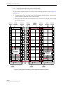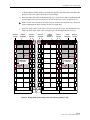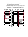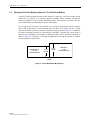
1
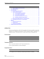
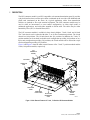
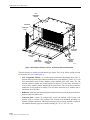
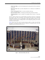
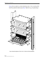
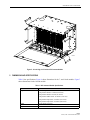
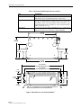
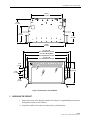
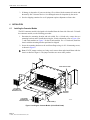
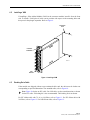
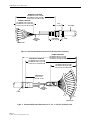
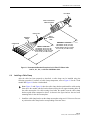
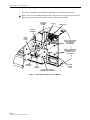
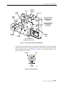
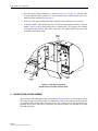
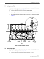
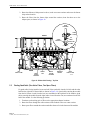
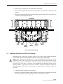
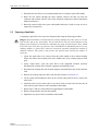
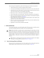
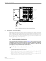
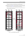
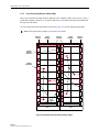
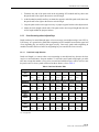
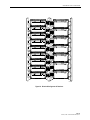
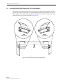
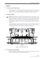
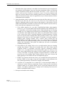
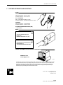
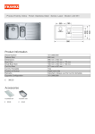
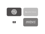
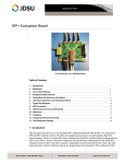
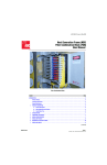
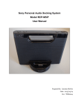
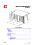
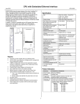
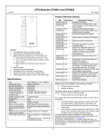
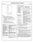
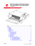
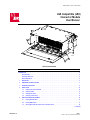
ADCP-93-089 • Issue 3 • March 2002
LGX Compatible (LSX)
Connector Module
User Manual)
17506-A
LSX Connector Module
Content
Page
INTRODUCTION . . . . . . . . . . . . . . . . . . . . . . . . . . . . . . . . . . . . . . . . . . . . . . . . . . . . . . . . . . . . . . . . . . . . . . . . . . . . . 2
Revision History . . . . . . . . . . . . . . . . . . . . . . . . . . . . . . . . . . . . . . . . . . . . . . . . . . . . . . . . . . . . . . . . . . . . . . . . 2
Trademark Information . . . . . . . . . . . . . . . . . . . . . . . . . . . . . . . . . . . . . . . . . . . . . . . . . . . . . . . . . . . . . . . . . . . 2
Related Publications . . . . . . . . . . . . . . . . . . . . . . . . . . . . . . . . . . . . . . . . . . . . . . . . . . . . . . . . . . . . . . . . . . . . . 2
1
DESCRIPTION . . . . . . . . . . . . . . . . . . . . . . . . . . . . . . . . . . . . . . . . . . . . . . . . . . . . . . . . . . . . . . . . . . . . . . . . . . 3
2
DIMENSIONS AND SPECIFICATIONS . . . . . . . . . . . . . . . . . . . . . . . . . . . . . . . . . . . . . . . . . . . . . . . . . . . . . . . . . . 7
3
UNPACKING THE PRODUCT . . . . . . . . . . . . . . . . . . . . . . . . . . . . . . . . . . . . . . . . . . . . . . . . . . . . . . . . . . . . . . . . 9
4
INSTALLATION . . . . . . . . . . . . . . . . . . . . . . . . . . . . . . . . . . . . . . . . . . . . . . . . . . . . . . . . . . . . . . . . . . . . . . . . 10
5
4.1
Installing the Connector Module . . . . . . . . . . . . . . . . . . . . . . . . . . . . . . . . . . . . . . . . . . . . . . . . . . . . . . 10
4.2
Installing a VAM . . . . . . . . . . . . . . . . . . . . . . . . . . . . . . . . . . . . . . . . . . . . . . . . . . . . . . . . . . . . . . . . . 11
4.3
Breaking Out a Cable . . . . . . . . . . . . . . . . . . . . . . . . . . . . . . . . . . . . . . . . . . . . . . . . . . . . . . . . . . . . . . 11
4.4
Installing a Cable Clamp . . . . . . . . . . . . . . . . . . . . . . . . . . . . . . . . . . . . . . . . . . . . . . . . . . . . . . . . . . . 13
CABLE ROUTING AND REPLACEMENT . . . . . . . . . . . . . . . . . . . . . . . . . . . . . . . . . . . . . . . . . . . . . . . . . . . . . . . . 16
5.1
Routing Stranded Cable . . . . . . . . . . . . . . . . . . . . . . . . . . . . . . . . . . . . . . . . . . . . . . . . . . . . . . . . . . . . 17
5.2
Routing Ribbon Cable . . . . . . . . . . . . . . . . . . . . . . . . . . . . . . . . . . . . . . . . . . . . . . . . . . . . . . . . . . . . . 17
5.3
Routing Quad Cable (Two Active Fibers, Two Spare Fibers) . . . . . . . . . . . . . . . . . . . . . . . . . . . . . . . . . . . . 18
(continued)
1220595 Rev A
Page 1
© 2003, ADC Telecommunications, Inc.
ADCP-93-089 • Issue 3 • March 2002
Content
6
7
Page
5.4
Replacing a Single Fiber or Fiber Pair Termination . . . . . . . . . . . . . . . . . . . . . . . . . . . . . . . . . . . . . . . . . 19
5.5
Replacing a Quad Cable . . . . . . . . . . . . . . . . . . . . . . . . . . . . . . . . . . . . . . . . . . . . . . . . . . . . . . . . . . . . 20
PATCH CORD ROUTING . . . . . . . . . . . . . . . . . . . . . . . . . . . . . . . . . . . . . . . . . . . . . . . . . . . . . . . . . . . . . . . . . . 21
6.1
Patch Cord Routing Within the LSX Module. . . . . . . . . . . . . . . . . . . . . . . . . . . . . . . . . . . . . . . . . . . . . . . 21
6.2
Routing Patch Cords on the LGX Bay . . . . . . . . . . . . . . . . . . . . . . . . . . . . . . . . . . . . . . . . . . . . . . . . . . . 22
Cross-Connecting Within a Stand-Alone Bay . . . . . . . . . . . . . . . . . . . . . . . . . . . . . . . . . . . . . . . 22
6.2.2
Cross-Connecting Between Adjacent Bays . . . . . . . . . . . . . . . . . . . . . . . . . . . . . . . . . . . . . . . . 24
6.2.3
Cross-Connecting to Non-Adjacent Bays . . . . . . . . . . . . . . . . . . . . . . . . . . . . . . . . . . . . . . . . . . 25
6.2.4
Routing Patch Cords Starting in the Lower Raceway . . . . . . . . . . . . . . . . . . . . . . . . . . . . . . . . . 26
6.2.5
Routing Patch Cords Starting in the Upper Raceway. . . . . . . . . . . . . . . . . . . . . . . . . . . . . . . . . . 28
6.3
Mounting 144-Position Modules Adjacent to 72 or 96 Position Modules . . . . . . . . . . . . . . . . . . . . . . . . . . . 30
6.4
Installing Modified Cable Retainers for 144-Position Modules. . . . . . . . . . . . . . . . . . . . . . . . . . . . . . . . . . 32
OPERATION . . . . . . . . . . . . . . . . . . . . . . . . . . . . . . . . . . . . . . . . . . . . . . . . . . . . . . . . . . . . . . . . . . . . . . . . . . 33
7.1
8
6.2.1
Removing a Cover for Easier Access . . . . . . . . . . . . . . . . . . . . . . . . . . . . . . . . . . . . . . . . . . . . . . . . . . . 33
7.2
Patching and Testing . . . . . . . . . . . . . . . . . . . . . . . . . . . . . . . . . . . . . . . . . . . . . . . . . . . . . . . . . . . . . . 33
7.3
Cleaning Connectors and Adapters . . . . . . . . . . . . . . . . . . . . . . . . . . . . . . . . . . . . . . . . . . . . . . . . . . . . 33
CUSTOMER INFORMATION AND ASSISTANCE . . . . . . . . . . . . . . . . . . . . . . . . . . . . . . . . . . . . . . . . . . . . . . . . . . . 34
_________________________________________________________________________________________________________
INTRODUCTION
This user manual describes the ADC LGX Compatible (LSX) Connector Module, and provides
instructions for installation and operation. The LSX connector module is designed to be
mounted on either a 19 inch (48.26 cm) or 23 inch (58.42) Lucent LGX compatible rack.
Revision History
quad cables and patch cord routing
ISSUE
DATE
REASON FOR CHANGE
Issue 1
06/2001
Original.
Issue 2
07/2001
Incorporate description of quad cables and patch cord routing.
Issue 3
04/2002
Updated to provide additional information on different chassis sizes and types.
Trademark Information
ADC is a registered trademark of ADC Telecommunications, Inc.
LGX is a registered trademark of Lucent Technologies.
Related Publications
Title
LGX Compatible (LSX) Combination Termination/Splice Module User Manual
Page 2
© 2003, ADC Telecommunications, Inc.
ADCP Number
93-095
ADCP-93-089 • Issue 3 • March 2002
1
DESCRIPTION
The LSX connector module is an LGX compatible, rack-mounted termination panel. It provides
a physical interface between fiber optic cables (terminated on the rear side of the bulkhead) and
patch cords (terminated on the front). In a typical application, cables from transmission
facilities are patched to fiber optic terminal equipment. The LSX connector module may be
used in either an interconnect or cross-connect configuration, in either single mode or
multimode applications, and with either stranded or ribbon cable. The cables may be either
Intrafacility Fiber (IFC) or Outside Plant (OSP).
The LSX connector module is available in three chassis heights: 7-inch, 9-inch, and 10-inch.
The 7-inch chassis can be ordered with either 72 or 96 fiber termination positions. The 9-inch
chassis has 144 positions. The 10-inch chassis has 216 positions. In addition, the 7-inch, 72
position module can be ordered in a double stack configuration providing 144 positions or in a
triple stack configuration providing 216 positions; the 9-inch module can be ordered in a triple
stack configuration providing 432 positions.
Figure 1 and Figure 2 show the main external features of the 7-inch, 72 position module and the
9-inch, 144 position module, respectively.
LGX
COMPATIBLE
CHASSIS
BULKHEAD
CONNECTOR
PACK
MOUNTING
BRACKET
PATCH CORD
GUIDE
REMOVABLE
FRONT COVER
PATCH CORD
DESIGNATION
CARD
REMOVABLE
RADIUS
LIMITERS
17424-A
Figure 1. Main External Features of 7-Inch, 72-Position LSX Connector Module
Page 3
© 2003, ADC Telecommunications, Inc.
ADCP-93-089 • Issue 3 • March 2002
LGX
COMPATIBLE
CHASSIS
BULKHEAD
CONNECTOR
PACK
MOUNTING
BRACKET
PATCH CORD
GUIDE
REMOVABLE
FRONT COVER
PATCH CORD
DESIGNATION
CARD
REMOVABLE
RADIUS
LIMITERS
17509-A
Figure 2. Main External Features of 9-Inch, 144 Position LSX Connector Module
The main features are similar for each chassis type shown. They are as follows (going from top
left clockwise in Figure 1 and Figure 2):
• LGX Compatible Chassis—is of solid metal construction and painted white. The 72
position and 96 position LSX connector modules have a rack height of 7 inches (17.8 cm)
and a maximum of nine of these modules can be installed in the LGX frame. The 144
position connector module has a rack height of 9 inches (22.9 cm) and a maximum of
seven of these modules can be installed in the LGX frame. The 216 position connector
module has a rack height of 10 inches (25.4 cm) and a maximum of six modules can be
installed in the LGX frame.
• Bulkhead—holds the pass-through adapters/connectors that provide the physical interface
between cables and patch cords.
• Connector Pack—6-pack (72 position LSX), 8-pack (96 position LSX), 12-pack (144
position LSX), or 18-pack (216 position LSX); mounts in the bulkhead, providing one
column of adapter/connectors. Individual connector packs are easily installed or replaced.
All standard connector types are available including FC, SC, FC, ST, LX.5, etc.
Page 4
© 2003, ADC Telecommunications, Inc.
ADCP-93-089 • Issue 3 • March 2002
• Patch Cord Guides—provide cable management in routing patch cords from connectors
to each side.
• Removable Front Cover—provides unimpeded access to connectors for installation of
patch cords.
• Patch Cord Designation Card—is used to record patch cord usage.
• Removable Radius Limiters—maintain proper bend radius protection for the fibers.
• Mounting Brackets—may be oriented to accommodate either 19-inch or 23-inch rack
mount.
The LSX connector module may be ordered loaded with connector packs only, or loaded with
both connector packs and pre-terminated, factory-installed cable. While not recommended,
field-installed connectors can be accommodated. Value-Added Modules (VAMs) are also
available for the LSX module, providing functions such as multiplexing, splitting, and variable
attenuation of optical signals.
Figure 3 shows a rear view of the 72 position connector module. As shown, the module has
cable guides for routing cable subunits to the rear connectors. The module also has a rear cable
designation card on the inside of the rear cover.
Figure 3. LSX Connector Module (Rear View)
Page 5
© 2003, ADC Telecommunications, Inc.
ADCP-93-089 • Issue 3 • March 2002
Figure 4 shows an example of a stacked configuration of three 7-inch, 72 position modules
providing 216 termination positions. Other stack configurations (2 x 72 for 144 positions, 3 x
144 for 432 positions) are similar in design. Figure 5 shows the 10 inch, 216 position module.
17520-A
Figure 4. Stacked Configuration of Three 7-Inch, 72 Position LSX Connector Modules
Page 6
© 2003, ADC Telecommunications, Inc.
ADCP-93-089 • Issue 3 • March 2002
17423-A
Figure 5. 10-Inch High, 216 Position LSX Connector Module
2
DIMENSIONS AND SPECIFICATIONS
Table 1 lists specifications. Figure 6 shows dimensions for the 7- and 9-inch modules. Figure 7
shows dimensions for the 10-inch module.
Table 1. LSX Connector Module Specifications
ITEM
DESCRIPTION
Height
72 and 96 position chassis: 7 inches (17.8 cm)
144 position chassis: 9 inches (22.86 cm)
216 position chassis: 10 inch (25.40 cm)
144 position double stack: 14 inches (35.56 cm)
216 position triple stack: 21 inches (53.34 cm)
Width
Depth
432 position triple stack: 27 inches (68.58 cm)
16.84 inches (42.8 cm)
11.00 inches (27.9 cm)
Page 7
© 2003, ADC Telecommunications, Inc.
ADCP-93-089 • Issue 3 • March 2002
Table 1. LSX Connector Module Specifications, continued
ITEM
DESCRIPTION
Rack Mount
Mounting bracket accommodates either 19-inch or 23-inch; 10inch chassis can be mounted with 4-inch or 5-inch recess
72 position LSX: 9 pounds (4.1 kg); 96 position LSX: 10 pounds
(4.5 kg); 144 position LSX: 13 pounds (5.9 kg); 216 position LSX:
13 pounds (5.9 kg); 144 position double stack:18 pounds (8.2 kg);
216 position triple stack: 27 pounds (12.3 kg); 432 position triple
stack: 39 pounds (17.7 kg)
72, 96, 144, or 216 per chassis (depending on type); stacks provide
144 (2 x 72), 216 (3 x 72), or 432 (3 x 144) terminations
Weight (unloaded)
Terminations
14.84 IN.
(37.7 CM)
11.0 IN.
(27.9 CM)
7.53 IN.
(19.1 CM)
5.0 IN.
(12.7 CM)
16.84 IN.
(42.8 CM)
22.15 (56.3 CM)
23-IN. RACK MOUNT (58.4 CM)
18.12 (46.0 CM)
19-IN. RACK MOUNT (48.3 CM)
1.0 IN.
(2.5 CM)
2.0 IN.
(5.1 CM)
1
1.0 IN.
(2.5 CM)
17422-A
1
7.0 IN. (17.8 CM) HEIGHT ON 72 OR 96 POSITION MODULES OR
9.0 (22.9 CM) HEIGHT ON 144 POSITION MODULES.
Figure 6. Dimensions for 7-Inch and 9-Inch Modules
Page 8
© 2003, ADC Telecommunications, Inc.
ADCP-93-089 • Issue 3 • March 2002
14.84 IN.
(37.7 CM)
11.0 IN.
(27.9 CM)
7.54 IN.
(19.2 CM)
5.0 IN.
(12.7 CM)
16.84 IN.
(42.8 CM)
22.15 (56.3 CM)
23-IN. RACK MOUNT (58.4 CM)
20.18 (51.3 CM) RECESSED
23-IN. RACK MOUNT (58.4 CM)
18.16 (46.1 CM)
19-IN. RACK MOUNT (48.3 CM)
1.0 IN.
(2.5 CM)
10.0 IN.
(25.4 CM)
2.0 IN.
(5.1 CM)
1.0 IN.
(2.5 CM)
17508-A
Figure 7. Dimensions for 10-Inch Module
3
UNPACKING THE PRODUCT
1. Inspect the exterior of the shipping container for evidence of rough handling that may have
damaged the contents of the container.
2. Unpack the module and accessories and check for possible damage.
Page 9
© 2003, ADC Telecommunications, Inc.
ADCP-93-089 • Issue 3 • March 2002
3. If damage is detected or if parts are missing, file a claim with the commercial carrier and
then notify ADC Customer Service. Save damaged carton for inspection by the carrier.
4. Save the shipping container for use if equipment requires shipment at a future date.
4
INSTALLATION
4.1
Installing the Connector Module
The LSX connector module is designed to be installed from the front side of the rack. To install
the connector module, use the following procedure.
1. Determine the mounting location and rack width. For a 19-inch rack, remove the two
mounting brackets and re-install them using the 19-inch orientation (refer to Figure 6 for
7- and 9-inch modules or Figure 7 for the 10-inch module). For a 23-inch rack, install the
chassis with the mounting brackets positioned as shipped.
2. Secure the mounting brackets to the rack front flange using six #12-24 mounting screws,
as shown in Figure 8.
Note: If LGX jumper retainers are being used, remove them and reinstall them with the
chassis as shown in Figure 8. The jumper retainers are not an ADC product.
RACK FRONT FLANGE
LGX JUMPER
RETAINER (NOT
PROVIDED BY ADC)
MOUNTING
BRACKET
LGX JUMPER
RETAINER (NOT
PROVIDED BY ADC)
17510-A
12-24X SCREW (6)
Figure 8. Installing the Connector Module (23-Inch Rack Shown)
Page 10
© 2003, ADC Telecommunications, Inc.
ADCP-93-089 • Issue 3 • March 2002
4.2
Installing a VAM
If installing a Value Added Module (VAM) in the connector module, install it from the front
side. To install a VAM, place it in the correct position with respect to the mounting holes and
then press in the plunger expanders. Refer to Figure 9.
MOUNTING
HOLE
PLUNGEREXPANDER
17544-A
VAM
MODULE
Figure 9. Installing a VAM
4.3
Breaking Out a Cable
If the module was shipped without a pre-terminated cable stub, the cable must be broken out
corresponding to specified dimensions. For stranded cable, refer to Figure 10.
Note: Figure 10 depicts an IFC cable. For OSP cable, use the same dimensions as shown
for the IFC cable. A blocking kit is also recommended. The blocking kit is not shown.
For IFC ribbon cable with 72, 96, or 144 fibers, refer to Figure 11. For IFC ribbon cable with
216 fibers, refer to Figure 12. For OSP ribbon cable, refer to Figure 12.
Page 11
© 2003, ADC Telecommunications, Inc.
ADCP-93-089 • Issue 3 • March 2002
BREAKOUT LENGTHS
7-IN. MODULE: 46.0 IN. (116.8 CM)
9-IN. MODULE: 48.0 IN. (121.9 CM)
+0.0 IN./-6.0 IN. (+0.0 CM/-15.2 CM)
FANOUT LENGTHS
7-IN. MODULE: 35.0 IN. (88.9 CM)
9-IN. MODULE: 37.0 IN. (94.0 CM)
+0.0 IN./-6.0 IN. (+0.0 CM/-15.2 CM)
2.0 IN.
(5.1 CM)
IFC CABLE
17605-A
SUBUNIT
DESIGNATION
LABEL
HEATSHRINK
6.0 IN. (15.2 CM)
CLAMP
CONNECTORS
Figure 10. Recommended Breakout Dimensions for Stranded Cable (IFC Shown)
CLAMP POSITIONS
BREAKOUT LENGTHS
7-IN. MODULE: 46.0 IN. (116.8 CM)
9-IN. MODULE: 48.0 IN. (121.9 CM)
+0.0 IN./-6.0 IN. (+0.0 CM/-15.2 CM)
7-IN. MODULE: 48.0 IN. (121.9 CM)
9-IN. MODULE: 50.0 IN. (127.0 CM)
+0.0 IN./-6.0 IN. (+0.0 CM/-15.2 CM)
FANOUT LENGTHS
7-IN. MODULE: 36.5 IN. (92.7 CM)
9-IN. MODULE: 38.5 IN. (97.8 CM)
+0.0 IN./-6.0 IN. (+0.0 CM/-15.2 CM)
TUBING LENGTH
6.5 IN. –0.5 IN.
(16.5 CM –1.3 CM)
SUBUNIT
DESIGNATION
LABEL
CLAMP
17543-A
CONNECTORS
Figure 11. Recommended Breakout Dimensions for 72-, 96-, or 144-Fiber IFC Ribbon Cable
Page 12
© 2003, ADC Telecommunications, Inc.
ADCP-93-089 • Issue 3 • March 2002
IFC CABLE
INSTALL PROTECTIVE
TUBES ON RIBBON
TIE
WRAP
FANOUT CHIP
INDIVIDUAL
FIBERS
END OF
PROTECTIVE
TUBE
BREAKOUT LENGTHS
CONNECTORS
FANOUT LENGTHS
7-IN. MODULE: 36.5 IN. (92.7 CM)
9-IN. MODULE: 38.5 IN. (97.8 CM)
216-POS. MODULE: 41.5 IN. (105.4 CM)
+0.0 IN./-6.0 IN. (+0.0 CM/-15.2 CM)
17507-A
7-IN. MODULE: 46.5 IN. (118.1 CM)
9-IN. MODULE: 48.5 IN. (123.2 CM)
216-POS. MODULE: 50.0 IN. (127.0CM)
+0.0 IN./-6.0 IN. (+0.0 CM/-15.2 CM)
Figure 12. Recommended Breakout Dimensions for 216-Fiber IFC Ribbon Cable
And 72-, 96-, 144-, or 216-Fiber OSP Ribbon Cable
4.4
Installing a Cable Clamp
After the cable has been prepared as described, a cable clamp can be installed using the
following procedure. For names of cable clamp components, refer to Figure 13 for the 7-inch
module and Figure 14 for the 9-inch module.
Note: Figure 13 and Figure 14 show the cable clamp bracket positioned for cable routing
from above the module with the bracket fastened using the two upper mounting holes in
the cable mount plate. For cable routing from below the module, turn the cable clamp
bracket upside down compared to how it is shown in the figure and use the two lower
mounting holes in the cable mount plate.
1. Install the cable clamp bracket on the clamp mount plate using two #12-24 screws. Be sure
to position the cable clamp bracket corresponding to the note above.
Page 13
© 2003, ADC Telecommunications, Inc.
ADCP-93-089 • Issue 3 • March 2002
2. Place the two standoffs in the standoff mounting holes in the cable clamp bracket.
Note: There are four standoff mounting holes. Either the two holes on the left or the two
holes on the right can be used together, not the two holes in the middle.
STANDOFF
MOUNTING
HOLE (4)
YOKE (2)
STANDOFF (2)
RUBBER
GROMMET
CABLE
CLAMP
COVER
CABLE CLAMP BRACKET
MOUNTING HOLES (2)
FOR OVERHEAD
CABLE ENTRY)
CABLE CLAMP BRACKET
MOUNTING HOLES (2)
FOR UNDER FLOOR
CABLE ENTRY)
STANDOFF
SCREW (2)
12-24X
SCREW (2)
17512-A
CABLE CLAMP BRACKET
(OVERHEAD CABLE POSITION)
Figure 13. Cable Clamp Components (7-Inch Module)
Page 14
© 2003, ADC Telecommunications, Inc.
CLAMP
MOUNT
PLATE
ADCP-93-089 • Issue 3 • March 2002
YOKE (2)
STANDOFF
MOUNTING
HOLE (4)
RUBBER
GROMMET
STANDOFF (2)
CABLE
CLAMP
COVER
CABLE CLAMP BRACKET
MOUNTING HOLES (2)
FOR UNDER FLOOR
CABLE ENTRY)
CABLE CLAMP BRACKET
MOUNTING HOLES (2)
FOR OVERHEAD
CABLE ENTRY)
STANDOFF
SCREW (2)
CLAMP
MOUNT
PLATE
12-24X
SCREW (2)
CABLE CLAMP BRACKET
(OVERHEAD CABLE POSITION)
17513-A
Figure 14. Cable Clamp Components (9-Inch Module)
3. Two rubber yokes and either three or four grommets (depending on the kit) are provided
with the cable clamp kit for securing the cable to the module. Select a grommet that, when
placed around the cable as shown in Figure 15, results in a gap of approximately zero to
0.030 inches (8 mm), as shown.
GROMMET
CABLE
GAP
0 - 0.30 IN.
(0 - 8 MM)
1440-A
Figure 15. Grommet Selection
Page 15
© 2003, ADC Telecommunications, Inc.
ADCP-93-089 • Issue 3 • March 2002
4. Stack the cable clamp components as shown in Figure 13 or Figure 14, with the cable
secured within the rubber grommet. For correct location of the cable breakout, refer to the
cable breakouts provided in subsection 4.3.
5. Secure the cable clamp components to the standoffs using standoff screws, as shown.
6. If desired, install a cable shield using any of the three shields shipped with the connector
module. Figure 16 shows the shield used for overhead cable. (The package also contains
an alternate shield used for under-floor cable and a box-shaped shield used with either
overhead or under-floor cable.)
CABLE
CLAMP
17514-A
CABLE
SHIELD
4-40X
SCREWS
(2)
Figure 16. Cable Shield Components
(Shield Shown is Used With Overhead Cable)
5
CABLE ROUTING AND REPLACEMENT
After preparing and clamping the cable as described in Section 4, above, you can route the cable
fibers into the rear of the LSX module. For instructions, refer to the separate procedures below
for stranded cable, ribbon cable, and quad cable. This section also contain instructions for
replacing one or more cable fibers if necessary. Separate procedures are provided for a single
fiber and quad cable.
Page 16
© 2003, ADC Telecommunications, Inc.
ADCP-93-089 • Issue 3 • March 2002
5.1
Routing Stranded Cable
If a stranded cable is being installed, route the cable fibers into the rear of the LSX connector
module using the following procedure (see Figure 17).
1. Position the cable breakout an inch (2.54 cm) after the cable clamp.
2. Route the subunits to the front center retainer, as shown, with the subunits broken out into
individual fibers at that location.
3. Route the fibers around the retainers and then fan them out to the adapter ports, as shown
in Figure 17.
FROM
OVERHEAD
CABLE
CLAMP
FRONT
CABLE
BREAKOUT
1.0 IN.
(2.54 CM)
REF
HEAT
SHRINK
SUBUNITS
REAR
LEFT
CABLE CLAMP
REAR
CENTER
RETAINER
FRONT
CENTER
RETAINER
INDIVIDUAL
SUBUNIT
RIGHT
CABLE CLAMP
BREAKOUT
SUBUNIT
HERE
17515-A
Figure 17. Stranded Cable Routing – Top View
5.2
Routing Ribbon Cable
If a ribbon cable is being installed, route the cable fibers into the rear of the LSX connector
module using the following procedure (see Figure 18)
1. Position the cable breakout immediately after the cable clamp, as shown.
Page 17
© 2003, ADC Telecommunications, Inc.
ADCP-93-089 • Issue 3 • March 2002
2. Route the ribbons (within protective tubes) to the rear center retainer and secure the fanout
chips at that location.
3. Route the fibers from the fanout chips around the retainers, then fan them out to the
adapter ports, as shown in Figure 18.
FROM
OVERHEAD
CABLE
CLAMP
FRONT
CABLE
BREAKOUT
TIE
WRAP
PROTECTIVE
TUBES
REAR
LEFT
CABLE CLAMP
FRONT
CENTER
RETAINER
FANOUT
CHIP
REAR
CENTER
RETAINER
INDIVIDUAL
SUBUNIT
RIGHT
CABLE CLAMP
17516-A
Figure 18. Ribbon Cable Routing – Top View
5.3
Routing Quad Cable (Two Active Fibers, Two Spare Fibers)
If a quad cable is being installed, route one-half of the quad cable into the left side and the other
half into the right side of the module (as shown in Figure 19). Quad cables entering the module
from the left (when viewed from the rear) are terminated on the right half of the module. Quad
cables entering the module from the right (when viewed from the rear) are terminated on the left
half of the module. Use the following procedure.
1. Terminate each working pair of fibers to the appropriate adapter locations.
2. Route the fibers through the cable retainers in the module to the rear center retainer.
3. Route spare fibers around the retainers and allow them to lie in the bottom of the module.
Page 18
© 2003, ADC Telecommunications, Inc.
ADCP-93-089 • Issue 3 • March 2002
4. Repeat steps 1 through 3 for each quad cable in the module.
5. Secure and label spare fiber cables as necessary with tie wraps or lace as required by local
practice.
6. Remove excess quad cable slack from the module. Work the slack back to the storage area
and secure it following local practice.
TOP VIEW
17517-A
ACTIVE
FIBER
SPARE
FIBER
FRONT
CENTER
RETAINER
BREAKOUT
POINTS
REAR
CENTER
RETAINER
INDIVIDUAL
SUBUNIT
Figure 19. Quad Cable Routing
5.4
Replacing a Single Fiber or Fiber Pair Termination
Sometimes it may be necessary to replace a fiber or pair of fibers when equipment upgrades
occur or when a fiber becomes damaged. To do this, use the following procedure.
Danger: Infrared radiation is invisible and can seriously damage the retina of the eye. Do not
look into the ends of any optical fiber. Do not look directly into the optical adapters of the
adapter packs. Exposure to invisible laser radiation may result. An optical power meter should
be used to verify active fibers. A protective cap or hood MUST be immediately placed over any
radiating adapter or optical fiber connector to avoid the potential of dangerous amounts of
radiation exposure. This practice also prevents dirt particles from entering the adapter or
connector.
1. Identify and label the fiber(s) to be removed.
2. Remove the connector from the adapter and place a dust cap on the connector end. Locate
the fiber cable in the module and gently remove it from the cable retainers.
Page 19
© 2003, ADC Telecommunications, Inc.
ADCP-93-089 • Issue 3 • March 2002
3. Determine the new fiber(s) to be terminated and remove it from the spare cable bundle.
4. Route the new fiber(s) through the cable retainers. Remove the dust cap from the
connector and clean the end face of the cable. Install the connector(s) into the appropriate
adapter/connector(s).
5. Route the removed cable to the spare cable bundle and secure it with tie wraps or lace as
required by local practice.
5.5
Replacing a Quad Cable
If replacing a quad cable, first remove the old quad cable using the following procedure.
Danger: Infrared radiation is invisible and can seriously damage the retina of the eye. Do not
look into the ends of any optical fiber. Do not look directly into the optical adapters of the
adapter packs. Exposure to invisible laser radiation may result. An optical power meter should
be used to verify active fibers. A protective cap or hood MUST be immediately placed over any
radiating adapter or optical fiber connector to avoid the potential of dangerous amounts of
radiation exposure. This practice also prevents dirt particles from entering the adapter or
connector.
1. Locate the quad cable to be removed from the cable bundle in the overhead racking.
Follow the cable to the breakout point in the module and verify working and spare fiber
pairs.
2. Using a light source, verify the spare fibers at the equipment locations specified.
Disconnect the working fibers from the equipment and install dust caps.
3. Disconnect the working fiber pair from the adapters, and install dust caps on the connector
ends.
4. Remove the working and spare fibers from the cable retainers. See Figure 19.
5. Cut the strain relief holding the cables in the vertical cable guide but do not remove the
strain relief.
6. Attach the end of a new strain relief to one end of each cut strain relief and use the cut
strain relief to pull in the new relief around the cable bundle.
7. Repeat steps 5 and 6 for each strain relief supporting the cable bundle.
8. Remove the quad cable from the cable bundle.
9. Tighten the new strain relief(s) around the cable bundle.
Page 20
© 2003, ADC Telecommunications, Inc.
ADCP-93-089 • Issue 3 • March 2002
After removing the old quad cable, perform the following steps to install a new quad cable.
1. Label the ends of the new cable in accordance with local practice.
2. Cut the strain relief holding the cable bundle to the rack but do not remove the strain relief.
3. Attach the end of a new strain relief to one end of each cut strain relief and use the cut
strain relief to pull in the new relief around the cable bundle.
4. Repeat steps 2 and 3 for each strain relief supporting the cable bundle.
5. Insert the quad cable into the cable bundle. Connect the working fibers to the equipment.
6. Route the quad cable through the radius limiters and retainers on the module and separate
the working and spare fiber pairs. See Figure 19.
7. Remove the dust caps from the working fiber pair, clean the end face of the connector, and
attach these fibers to the module connectors.
8. Remove the cable slack from the working and spare fiber pairs on the module and route
the excess into the overhead cable bundle.
9. Tighten the new strain relief(s) around the cable bundle.
6
PATCH CORD ROUTING
Cross-connect patch cords on the LSX modules and LGX frame must be carefully routed to
ensure they are properly protected. For details, refer to the following topics.
Danger: Infrared radiation is invisible and can seriously damage the retina of the eye. Do not
look into the ends of any optical fiber. Do not look directly into the optical adapters of the
adapter packs. Exposure to invisible laser radiation may result. An optical power meter should
be used to verify active fibers. A protective cap or hood MUST be immediately placed over any
radiating adapter or optical fiber connector to avoid the potential of dangerous amounts of
radiation exposure. This practice also prevents dirt particles from entering the adapter or
connector.
Note: Whenever connecting patch cords, inspect and clean all connectors and adapters
following the cleaning guidelines provided in Section 7.3 on page 33.
6.1
Patch Cord Routing Within the LSX Module
Route patch cords vertically down the front of the connector pack on each module then left or
right through the guides and radius limiters on the LSX module (see Figure 20).
Page 21
© 2003, ADC Telecommunications, Inc.
ADCP-93-089 • Issue 3 • March 2002
CONNECTOR
PACK
PATCH CORD
GUIDE
17518-A
RADIUS
LIMITER
Figure 20. LSX Module Patch Cord Guides and Radius Limiters
6.2
Routing Patch Cords on the LGX Bay
When routing patch cords on the LGX bay, allow for a minimum of 6 in. (152 mm) of slack loop
in the vertical trough. This loop aids in the tracing of patch cords and also facilitates removing a
patch cord from the bundle. Additional fiber slack should be expected when installing a set of
pre-connectorized patch cords. Refer to the following topics for patch cord details for a standalone bay, adjacent bays, and non-adjacent bays.
6.2.1
Cross-Connecting Within a Stand-Alone Bay
Cross-connecting within a stand-alone bay (shown in Figure 21) may be required when facility
and equipment terminations are intermixed Most cross-connection routing within a stand-alone
bay should be done with 5 meter (16.5 ft.) patch cords. Shorter 3 meter (9.9 ft.) patch cords can
be used when both ends are terminated in the top half of the bay.
Use the following procedure to route patch cords on a stand-alone bay:.
Note: Three patch cord examples (A, B, and C) are shown.
1. Loop the patch cord across the upper raceway.
2. Route the right side of the patch cord down through the right vertical trough to the LSX
module where the right side of the patch cord will be terminated.
3. Route the left side of the patch cord down through the left vertical trough to the LSX
module where the left side of the patch cord will be terminated.
Page 22
© 2003, ADC Telecommunications, Inc.
ADCP-93-089 • Issue 3 • March 2002
4. Route the ends of the patch cords inward from the vertical troughs to the respective points
of termination. Connect the two ends of the patch cord at the desired adapters.
Note: On same side terminations, one end of the patch cord will extend across the midline
of the bay (as shown in Figure 21 for patch cords B and C). On opposite side terminations
(patch cord A), the patch cord will not extend across the midline of the bay.
5. Adjust the slack length at both ends of the patch cord to about equal length and dress the
excess length within the jumper retainers.
VERTICAL
TROUGH
UPPER
RACEWAY
VERTICAL
TROUGH
VERTICAL
TROUGH
UPPER
RACEWAY
1
VERTICAL
TROUGH
1
2
A
3
2
3
4
A
5
JUMPER
RETAINERS
B
B
4
C
C
5
BAY
BAY
OPPOSITE SIDE
TERMINATIONS
SAME SIDE
TERMINATIONS
17536-A
Figure 21. Cross-Connecting Within a Stand-Alone Bay
Page 23
© 2003, ADC Telecommunications, Inc.
ADCP-93-089 • Issue 3 • March 2002
6.2.2
Cross-Connecting Between Adjacent Bays
Most cross-connection routing between adjacent racks should be done with 6 meter (19.8 ft.)
patch cords. Shorter 4 meter (13.2 ft.) patch cords can be used when both ends are terminated in
the top left of the frame.
To cross-connect between adjacent bays (shown in Figure 22), use the following procedure.
Note: Three patch cord examples (A, B, and C) are shown.
VERTICAL
TROUGH
UPPER
RACEWAY
VERTICAL
TROUGHS
UPPER
RACEWAY
VERTICAL
TROUGH
3
JUMPER
SUPPORT
BRACKET
B
JUMPER
RETAINERS
2
B
C
1
A
4
A
C
4
BAY
BAY
17537-A
Figure 22. Routing Patch Cords Between Adjacent Bays
Page 24
© 2003, ADC Telecommunications, Inc.
ADCP-93-089 • Issue 3 • March 2002
1. Terminate one end of the patch cord on the originating LSX module and bay, then route
the patch cord left or right to the nearest vertical trough.
2. At the destination module and bay, terminate the opposite end of the patch cord, then route
the patch cord left or right to the nearest vertical trough.
3. Loop the patch cord over the upper raceway or jumper support bracket to the adjacent rack.
4. Adjust the slack length at both ends of the patch cord to about equal length and dress the
excess length within the jumper retainers.
6.2.3
Cross-Connecting to Non-Adjacent Bays
Patch cords may be routed through upper or lower raceways to non-adjacent bays in an LGX or
LSX lineup. As a general rule, patch cords originating in LSX modules located in the upper half
of an originating bay are routed to the upper raceway. Conversely, patch cords originating in
modules located in the lower half of an originating bay are routed to the lower raceway.
6.2.3.1
Patch Cord Length Selection
Patch cord length is a concern when cross-connecting to non-adjacent bays because the bays
may be at various distances from one another. To select the correct patch cord length, you must
take into account the number of bays to be traversed and which raceways will be used to route
the patch cord. To select a patch cord based on these factors, refer to Table 2.
Table 2. Patch Cord Selection Table
BOTTOM HALF ORIGIN/BOTTOM HALF DESTINATION (LOWER TO LOWER RACEWAY)
NUMBER OF
BAYS
JUMPER
LENGTH
3, 4
5, 6
7, 8, 9
10, 11, 12
13
14, 15, 16
17,18
19, 20, 21
N/A
7.6 m
9.2 m
10.7 m
12.2 m
13.6 m
15.2 m
16.6 m
18.1 m
N/A
(30 ft.)
(35 ft.)
(40 ft.)
(45 ft.)
(50 ft.)
(55 ft.)
(60 ft.)
(25 ft.)
BOTTOM HALF ORIGIN/TOP HALF DESTINATION (LOWER TO UPPER RACEWAY)
NUMBER OF
BAYS
JUMPER
LENGTH
3
4, 5
6, 7
8, 9, 10
11, 12
13, 14
15, 16, 17
18, 19, 20
21
6.1 m
7.6 m
9.2 m
10.7 m
12.2 m
13.6 m
15.2 m
16.6 m
18.1 m
(20 ft.)
(25 ft.)
(30 ft.)
(35 ft.)
(40 ft.)
(45 ft.)
(50 ft.)
(55 ft.)
(60 ft.)
TOP HALF ORIGIN/TOP HALF DESTINATION (UPPER TO UPPER RACEWAY)
NUMBER OF
BAYS
JUMPER
LENGTH
3
4, 5
6, 7, 8
9, 10
11, 12
13, 14
15, 16, 17
18, 19
20, 21
4.9 m
6.1 m
7.6 m
9.2 m
10.7 m
12.2 m
13.6 mm
15.2 m
16.6 m
(16 ft.)
(20 ft.)
(25 ft.)
(30 ft.)ft.)
(35 ft.)
(40 ft.)
(45 ft.)
(50 ft.)
(55 ft.)
TOP HALF ORIGIN/BOTTOM HALF DESTINATION (UPPER TO LOWER RACEWAY)
NUMBER OF
BAYS
JUMPER
LENGTH
3, 4
5, 6, 7
8, 9
10, 11
12, 13
14, 15, 16
17, 18
19, 20, 21
N/A
6.1 m
7.6 m
9.2 m
10.7 m
12.2 m
13.6 m
15.2 m
16.6 m
N/A
(20 ft.)
(25 ft.)
(30 ft.)
(35 ft.)
(40 ft.)
(45 ft.)
(50 ft.)
(55 ft.)
N/A: Not applicable
Page 25
© 2003, ADC Telecommunications, Inc.
ADCP-93-089 • Issue 3 • March 2002
6.2.4
Routing Patch Cords Starting in the Lower Raceway
To cross-connect starting in the lower raceway, use the following procedure. Refer to Figure 23
and Figure 24.
1. Terminate one end of each patch cord at the originating module and bay, then route the
patch cord left or right to the nearest vertical trough.
2. Route the end of the patch cord terminated in step 1 down the left or right vertical trough
to the lower raceway.
VERTICAL
TROUGH
JUMPER
RETAINERS
VERTICAL
TROUGHS
VERTICAL
TROUGHS
JUMPER
SUPPORT
BRACKET
VERTICAL
TROUGHS
UPPER
RACEWAYS
VERTICAL
TROUGH
4
1
ORIGINATING
TERMINATION
LOCATIONS
DESTINATION
TERMINATION
LOCATIONS
2
3
5
BAY
BAY
BAY
17538-A
LOWER
RACEWAY
LOWER
RACEWAY
LOWER
RACEWAY
Figure 23. Routing Patch Cords Starting in the Lower Raceway (Bottom to Bottom)
Page 26
© 2003, ADC Telecommunications, Inc.
ADCP-93-089 • Issue 3 • March 2002
3. At the destination module and bay, terminate the opposite end of the patch cord, then route
the patch cord left or right to the nearest vertical trough.
4. Route the end of the patch cord terminated in step 3 up the left or right vertical trough and
over the upper raceway across the top of one bay as shown in Figure 23 and Figure 24.
Note: Use the lower trough as the main raceway between non-adjacent bays. Route the
patch cord through the upper raceway for one bay length only.
5. Insert the patch cords in the lower raceway between the origin and destination bays.
Adjust the slack loops in the vertical troughs to prevent buildup within the raceway.
JUMPER
RETAINERS
VERTICAL
TROUGH
VERTICAL
TROUGHS
JUMPER
SUPPORT
BRACKETS
VERTICAL
TROUGHS
UPPER
RACEWAYS
VERTICAL
TROUGHS
VERTICAL
TROUGH
5
4
2
ORIGINATING
TERMINATION
LOCATIONS
DESTINATION
TERMINATION
LOCATIONS
1
3
BAY
BAY
BAY
17540-A
Figure 24. Routing Patch Cords Starting in the Lower Raceway (Bottom to Top)
Page 27
© 2003, ADC Telecommunications, Inc.
ADCP-93-089 • Issue 3 • March 2002
6.2.5
Routing Patch Cords Starting in the Upper Raceway
To cross-connect starting in the upper raceway, use the following procedure. Refer to Figure 25
and Figure 26.
1. Terminate one end of each patch cord on the originating module and bay and then route
the patch cord left or right to the nearest vertical trough.
2. Route the end of the patch cord terminated in step 1 up the left or right vertical trough to
the upper raceway.
JUMPER
RETAINERS
VERTICAL
TROUGH
VERTICAL
TROUGHS
JUMPER
SUPPORT
BRACKETS
VERTICAL
TROUGHS
UPPER
RACEWAYS
VERTICAL
TROUGHS
VERTICAL
TROUGH
5
4
2
ORIGINATING
TERMINATION
LOCATIONS
DESTINATION
TERMINATION
LOCATIONS
1
3
BAY
BAY
BAY
17540-A
Figure 25. Routing Patch Cords in the Upper Raceway (Top to Top)
Page 28
© 2003, ADC Telecommunications, Inc.
ADCP-93-089 • Issue 3 • March 2002
3. At the destination module and bay, terminate the opposite end of the patch cord and then
route the patch cord left or right to the nearest vertical trough.
4. Route the patch cord terminated in step 3 up the left or right vertical trough as shown in
Figure 25 and Figure 26.
5. Insert the patch cords in the upper raceway between the origin and destination bays.
Adjust the slack loops in the vertical troughs to prevent buildup within the raceway.
JUMPER
RETAINERS
VERTICAL
TROUGH
VERTICAL
TROUGHS
JUMPER
SUPPORT
BRACKETS
VERTICAL
TROUGHS
UPPER
RACEWAYS
VERTICAL
TROUGHS
VERTICAL
TROUGH
5
2
4
ORIGINATING
TERMINATION
LOCATIONS
1
DESTINATION
TERMINATION
LOCATIONS
3
BAY
BAY
BAY
17541-A
Figure 26. Routing Patch Cords in the Upper Raceway (Top to Bottom)
Page 29
© 2003, ADC Telecommunications, Inc.
ADCP-93-089 • Issue 3 • March 2002
6.3
Mounting 144-Position Modules Adjacent to 72 or 96 Position Modules
Lucent LGX fiber distribution frames with a depth of 12 inches (30.1 cm) are typically used to
mount LSX 72 position or 96 position connector modules. When mounting 144 position
connector modules, Lucent LGX fiber distribution frames with a depth of 15 inches (38.1 cm)
are recommended to accommodate the greater cable density.
If a 15 inch deep LGX frame is not available, use a rear duct extension kit (Lucent catalog #
FEX1A-FB or equivalent) to extend backward the rear doors of the frame. The new 15 inch
deep frame will line up with any existing 12 inch deep frame as shown in Figure 27. In addition,
the relative mounting locations for Lucent JR4A-1 and JR4C-1 retainer caps, on the front of
adjacent bays containing LSX modules of different heights, will be skewed horizontally as
shown in Figure 28. The degree of retainer misalignment varies with the number of modules
used to populate the adjacent bay.
EXISTING LINE-UP
0F 72 OR 96
POSITION MODULES
12.0 IN.
(30.5 CM)
15.0 IN.
(38.1 CM)
NEW LINE-UP
0F 144
POSITION MODULES
TOP VIEW
(FRONT)
Figure 27. Front-to-Back Module Misalignment
Page 30
© 2003, ADC Telecommunications, Inc.
16077-A
ADCP-93-089 • Issue 3 • March 2002
17597-A
Figure 28. Relative Misalignment of Retainers
Page 31
© 2003, ADC Telecommunications, Inc.
ADCP-93-089 • Issue 3 • March 2002
6.4
Installing Modified Cable Retainers for 144-Position Modules
The existing cable retainers on the rear of each Lucent rack must be replaced with new, highercapacity cable retainers when LSX 144 position connector modules are installed. Two new top
cable retainers are available (ADC catalog # LSX-ACC001) to provide a left and right cable
orientation at the top of each rack upright (see Figure 29).
LEFT
ORIENTATION
RIGHT
ORIENTATION
BAY
17542-A
Figure 29. Top Cable Retainer (Left Orientation Shown)
Page 32
© 2003, ADC Telecommunications, Inc.
ADCP-93-089 • Issue 3 • March 2002
7
7.1
OPERATION
Removing a Cover for Easier Access
The front and rear covers of the chassis may be removed to provide easier access for cable
routing. To remove a cover, lift it straight out of the hinges. To replace a cover, position the
hinge edge of the cover on the hinges and press inward to push the edge into the hinges.
7.2
Patching and Testing
Danger: Infrared radiation is invisible and can seriously damage the retina of the eye. Do not
look into the ends of any optical fiber. Do not look directly into the optical adapters of the
adapter packs. Exposure to invisible laser radiation may result. An optical power meter should
be used to verify active fibers. A protective cap or hood MUST be immediately placed over any
radiating adapter or optical fiber connector to avoid the potential of dangerous amounts of
radiation exposure. This practice also prevents dirt particles from entering the adapter or
connector.
Testing and patching of optical circuits are done on the front of the LSX module using patch
cords. Whenever patch cords are installed, route them down and to the side, as with crossconnect patch cords. Refer to Figure 30 below; see also Figure 20 on page 22.
TOP VIEW
17519-A
Figure 30. Correct Routing of Patch Cords
7.3
Cleaning Connectors and Adapters
Whenever connecting or disconnecting connectors to an adapter, the connectors and adapters
should be carefully cleaned. Observe the following guidelines:
Page 33
© 2003, ADC Telecommunications, Inc.
ADCP-93-089 • Issue 3 • March 2002
1. Remember that a single connector is one-third of an interconnection system comprised of
two connectors and an adapter: if any one of the three components is dirty, it is likely that
all three components are dirty and must be cleaned. Don't mate a “clean” connector with
another connector whose cleanliness is unknown or suspect. If necessary, disconnect and
inspect an installed connector before installing another (clean) connector. Cleaning the
adapter is often also necessary when it is apparent that two pre-cleaned connectors become
contaminated after installation.
2. Inspect the endface at 200X: adjust the microscope to place the fiber in the upper center of
the field of view and rotate the connector to view a 360° area. Focus on the fiber, and
adjust the illuminator and the monitor contrast and brightness so that particles ON the
endface and ADJACENT the endface are observed (for some inspection systems, this may
involve more than one adjustment at each viewing).
a. If the endface appears to be “very dirty” (liquid-looking droplets, many particles,
smears, etc.), pre-clean the endface with a lint-free laboratory tissue (Kimwipes® EXL or equivalent) or a Fiberclean cartridge cleaner. When using this type of a cleaning
cartridge, use a very light pressure to the non-woven cleaning fabric, apply 2-3 strokes
over the fabric with a slight rotation of the endface, keep the endface surface parallel
to the cleaning fabric (this is especially important on angled connectors!), and DO
NOT reuse any area of the cartridge fabric. When possible, clean the “sides” (outside
diameter) of the ferrule as well as the endface. If available, use alcohol (reagent or
technical grade isopropyl alcohol) with a lint-free tissue: moisten (do not
SATURATE!) several folds of the tissue with a very small amount of alcohol and
firmly rub/twist the alcohol-moistened portion of the tissue onto the connector
endface, then immediately “final polish” the endface per (b) below or with another
folded dry laboratory tissue.
b. If the endface is just “slightly” dirty (a few very small particles), then use a cleaning
cartridge that contains a finely-woven cleaning fabric (the “Reel Cleaner Optical
Connector Cleaner” or equivalent) to provide a spot-free, scratch-free connector
endface. Use a very light pressure to the cleaning fabric, apply 2-3 strokes over the
fabric with a slight rotation of the endface, keep the endface surface parallel to the
cleaning media (this is especially important on angled connectors!), and DO NOT
reuse any area of the cartridge fabric. Folding a lint-free tissue into 4-6 layers and
lightly applying it to the endface will also accomplish this purpose.
c. REJECT any connectors that do not clean up, are scratched (NO defects permitted in
the fiber CORE!), or have many or large pits in the endface ceramic adjacent to the
fiber (within approximately 100 microns or roughly a fiber diameter).
d. Avoid the use of compressed air or “canned gas” to clean non-angled endfaces. If
canned gas is used to clean any components, exercise extreme care not to tip/tilt the
container during its use (liquid material will be ejected and deposited onto the
endface). Low quality compressed air or improper use of canned gas can cause more
endface contamination than it removes.
3. Re-inspect each endface after cleaning.
Page 34
© 2003, ADC Telecommunications, Inc.
ADCP-93-089 • Issue 3 • March 2002
8
CUSTOMER INFORMATION AND ASSISTANCE
PHONE:
EUROPE
Sales Administration: +32-2-712-65 00
Technical Assistance: +32-2-712-65 42
U.S.A. OR CANADA
Sales: 1-800-366-3891 Extension 73000
Technical Assistance: 1-800-366-3891 Extension 73475
ELSEWHERE
Sales Administration: +1-952-938-8080
Technical Assistance: +1-952-917-3475
SYSTEM INTEGRATION DIVISION (SID)
+1-952-294-3600
WRITE:
U.S.A.
ADC TELECOMMUNICATIONS, INC
PO BOX 1101,
MINNEAPOLIS, MN 55440-1101, USA
U.S.A.
ADC EUROPEAN CUSTOMER SERVICE, INC
BELGICASTRAAT 2,
1930 ZAVENTEM, BRUSSELS, BELGIUM
PRODUCT INFORMATION AND TECHNICAL ASSISTANCE:
WWW.ADC.COM
[email protected]
13944-G
Contents herein are current as of the date of publication. ADC reserves the right to change the contents without prior notice.
In no event shall ADC be liable for any damages resulting from loss of data, loss of use, or loss of profits and ADC further
disclaims any and all liability for indirect, incidental, special, consequential or other similar damages. This disclaimer of
liability applies to all products, publications and services during and after the warranty period. This publication may be
varified at any time by contacting ADC's Technical Assistance Center.
© 2003, ADC Telecommunications, Inc.
All Rights Reserved
Printed in U.S.A
Page 35
© 2003, ADC Telecommunications, Inc.