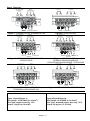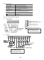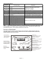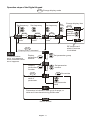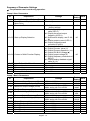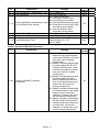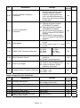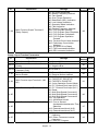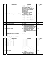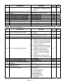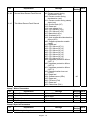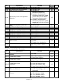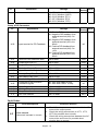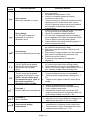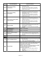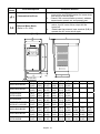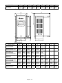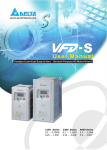
1
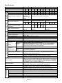
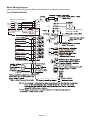
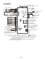
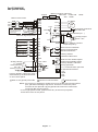
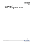
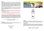
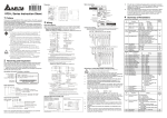
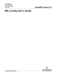
Preface
Thank you for choosing DELTA’s high-performance VFD-S Series. The VFD-S Series is
manufactured with high-quality components and materials and incorporates the latest microprocessor
technology available.
Getting Started
This quick start will be helpful in the installation and parameter setting of the AC motor drives. To
guarantee safe operation of the equipment, read the following safety guidelines before
connecting power to the AC motor drives. For detail information, refer to the VFD-S User Manual
on the CD supplied with the drive.
DANGER!
1.
2.
3.
4.
5.
6.
7.
AC input power must be disconnected before any wiring to the AC motor drive is made.
A charge may still remain in the DC-link capacitors with hazardous voltages, even if the power
has been turned off. To prevent personal injury, please ensure that power has turned off before
opening the AC motor drive and wait ten minutes for the capacitors to discharge to safe voltage
levels.
Never reassemble internal components or wiring.
The AC motor drive may be destroyed beyond repair if incorrect cables are connected to the
input/output terminals. Never connect the AC motor drive output terminals U/T1, V/T2, and
W/T3 directly to the AC mains circuit power supply.
Ground the VFD-S using the ground terminal. The grounding method must comply with the laws
of the country where the AC motor drive is to be installed. Refer to the Basic Wiring Diagram.
VFD-S series is used only to control variable speed of 3-phase induction motors, NOT for 1phase motors or other purpose.
VFD-S series shall NOT be used for life support equipment or any life safety situation.
WARNING!
1.
2.
3.
DO NOT use Hi-pot test for internal components. The semi-conductor used in AC motor drive
easily damage by high-pressure.
There are highly sensitive MOS components on the printed circuit boards. These components
are especially sensitive to static electricity. To prevent damage to these components, do not
touch these components or the circuit boards with metal objects or your bare hands.
Only quality person is allowed to install, wire and maintain AC motor drive.
CAUTION!
1.
2.
3.
4.
5.
6.
Some parameters settings can cause the motor to run immediately after applying power.
DO NOT install the AC motor drive in a place subjected to high temperature, direct sunlight,
high humidity, excessive vibration, corrosive gases or liquids, or airborne dust or metallic
particles.
Only use AC motor drives within specification. Failure to comply may result in fire, explosion or
electric shock.
To prevent personal injury, please keep children and unqualified people away from the
equipment.
When the motor cable between AC motor drive and motor is too long, the layer insulation of the
motor may be damaged. Please use a frequency inverter duty motor or add an AC output
reactor to prevent damage to the motor. Refer to appendix B Reactor for details.
The rated voltage for AC motor drive must be ≤240V (≤480V for 460V models) and the mains
supply current capacity must be ≤5000A RMS (≤10000A RMS for the ≥40hp (30kW) models).
English- 1
Specifications
Output Rating
Voltage Class
Model Number VFD-XXXS
Max. Applicable Motor Output (kW)
Max. Applicable Motor Output (HP)
Rated Output Capacity (KVA)
Rated Output Current (A)
Maximum Output Voltage (V)
Rated Frequency (Hz)
Control
Characteristics
Input Rating
Rated Input Current (A)
Input Current for 1-phase model
drive to be used as 3-phase
model drive
Rated Voltage/Frequency
Voltage/Freq. Tolerance
Control System
Output Frequency Resolution
Torque Characteristics
Overload Endurance
Accel/Decel Time
V/F Pattern
Stall Prevention Level
Operating Characteristics
Keypad
Frequency
Setting
Operation
Setting Signal
External
Signal
Keypad
-- --
1.6
3.0
5.1
8.4
--
022
2.2
3.0
4.4
5.5
6.9
-- --
100/110/120 VAC 200/208/220/240 VAC
380/400/415/480 VAC
50/60 Hz
50/60Hz
50/60Hz
Voltage: ±10%, Frequency: ±5%
SPWM (Sinusoidal Pulse Width Modulation, carrier frequency 3k-10kHz)
0.1Hz
Including the auto-torque, auto-slip compensation; starting torque can be
150% at 5Hz
150% of rated current for 1 minute
0.1to 600 second (2 Independent settings for Accel/Decel Time)
V/F pattern adjustable
20 to 250%, Setting of Rated Current
Setting by
or Potentiometer
Potentiometer-5KΩ/0.5W, DC 0 to +10V or 0 to +5V (Input impedance
47KΩ), RS-485 interface, 4 to 20mA (Input impedance 250Ω); MultiFunction Inputs 1 to 5 (7 steps, Jog, up/down)
Setting by RUN, STOP
External
Signal
M0 to M5 can be combined to offer various modes of operation, RS-485
serial interface (MODBUS).
Multi-step selection 0 to7, Jog, accel/decel inhibit, first/second accel/decel
Multi-Function Input Signal
switch, counter, 8-step PLC operation, external Base Block (NC, NO),
increase/decrease Master Frequency
AC Drive Operating, Frequency Attained, Non-zero, Base Block, Fault
Multi-Function Output Indication
Indication, Local/Remote indication, PLC Operation indication.
Analog Output Signal
Analog frequency/current signal output.
Installation Location
Pollution Degree
AVR, S-Curve, Over-Voltage/Over-Current Stall Prevention, Fault Records,
Adjustable Carrier Frequency, DC Braking, Start Frequency for DC Braking,
Momentary Power Loss restart, Frequency Limits, Parameter Lock/Reset,
PID Feedback Control, Reverse Inhibition, etc.
VFD002S21E, VFD004S21E, VFD004S43E, VFD007S21E, VFD007S43E,
VFD015S21E, VFD015S43E, VFD022S21E, VFD022S43E
Self-testing, Over Voltage, Over Current, Under Voltage, Overload,
Overheating, External Fault, Electronic thermal, Ground Fault.
Forced air-cooling (ONLY FOR 022S2XA/B; XXXS43A/B/E 1HP~3HP;
XXXSXXD; XXXS21E 400W~3HP). Others are Natural air-cooling.
Altitude 1,000 m or below, keep from corrosive gasses, liquid and dust
2
Ambient Temperature
Storage Temperature
Ambient Humidity
Vibration
-10°C to 40°C (Non-Condensing and not frozen)
-20°C to 60°C
Below 90% RH (non-condensing)
9.80665m/s2 (1G) less than 20Hz, 5.88m/s2 (0.6G) at 20 to 50Hz
Other Function
Built-in EMI Filter
Protection
Cooling
Enviroment
115V Class
230V Class
460V Class
002 004 007 002 004 007 015 022 004 007 015
0.2 0.4 0.75 0.2 0.4 0.75 1.5 2.2 0.4 0.75 1.5
0.25 0.5 1.0 0.25 0.5 1.0 2.0 3.0 0.5 1.0 2.0
0.6 1.0 1.6 0.6 1.0 1.6 2.9 4.2 1.2 2.0 3.3
1.6 2.5 4.2 1.6 2.5 4.2 7.5 11.0 1.5 2.5 4.2
3-phase
Proportional to
3-phase Proportional to Input Voltage
Twice the Input
Voltage
1.0 to 400 Hz
Single phase
Single/3-phase model drive
3-phase
4.9/ 6.5/ 9.7/ 15.7/ 24/
6
9
18
1.7 2.9 5.1
1.9 2.7 5.1 9.0
15
English- 2
Basic Wiring Diagram
Users must connect wiring according to the following circuit diagram shown below.
For VFDXXXSXXA/B/D/U
Main Circuit Power
NFB
R/L1
S/L2
T/L3
Recommended Circuit
when power supply
is turned OFF by a
fault output
E
R/L1
S/L2
T/L3
SA
MC
OFF
ON
MC
RB
RC
Grounding resistance
less than 100
17V
4.7k
17V
4.7k
17V
4.7k
17V
4.7k
4.7k
17V
17V
17V
4.7k
47K
English- 3
For VFDXXXSXXE
NPN (sink mode)
Braking resistor (optional)
select 80Ω 120W, 200Ω 120W
400Ω 120W
Jumper
Main Circuit Power
NFB
R/L1
S/L2
T/L3
Recommended Circuit
when power supply
is turned OFF by a
fault output
+1
E
R/L1
S/L2
T/L3
SA
MC
OFF
ON
MC
Factory default
Forward/Stop
Reverse/Stop
Reset
Multi-step 1
Multi-step 2
Multi-step 3
Comm. signal (sink)
Analog voltage 3
0~10VDC
Potentiometer Pot. 2
3K~5KΩ
Analog current 1
RB
RC
+2/B1
+17V
CPU
2.4Ω
17V
11V
M0
M2
NPN
M3
PNP
J2
GND
E
+10V 10mA
(MAX)
2 1
AVI 3
47KΩ
250Ω
GND
AC Motor
IM
3~
Grounding resistance
less than 100Ω
E
47ΩAFM
47KΩ
RA
RB
RC
M5
Factory default: output freq. (Pot.)
determined by the Potentiometer
on the control panel.
Main circuit (power) terminals
V/T2
W/T3
GND
M1
M4
B2
U/T1
Potentiometer(1KΩ)
+
-
Analog output
DC 0~10V
Factory default: indicate
output frequency
Multi-function indication
output contacts below
120VAC/24VDC 5A
Factory default:
indicates malfunction
Mo1
Multi-function Photocoupler
output below 48VDC 50mA
Factory default: Indicates
MCM during operation
RJ-11
6←1
Control circuit terminals
RJ-11 communication port with
RS-485 serial interface
1:17V
2:GND
3:SG4:SG+
Shielded leads
NOTE: Do not plug in a Modem or telephone line to the RS-485 communication
port, permanent damage may result. Terminal 1 & 2 are the power
sources for the optional copy keypad and should not be used while
using RS-485 communication.
* If it is single phase model, please select any of the two input power
terminals in main circuit power.
English- 4
For VFDXXXSXXE
PNP (source mode)
Braking resistor (optional)
select 80Ω 120W, 200Ω 120W
400Ω 120W
Jumper
Main Circuit Power
NFB
R/L1
S/L2
T/L3
Recommended Circuit
when power supply
is turned OFF by a
fault output
+1
E
R/L1
S/L2
T/L3
SA
MC
OFF
ON
MC
RB
RC
+2/B1
B2
U/T1
+17V
CPU
2.4Ω
V/T2
W/T3
Reverse/Stop
Reset
Multi-step 1
Multi-step 2
Multi-step 3
Analog voltage 3
0~10VDC
Potentiometer Pot. 2
3K~5KΩ
Analog current 1
17V
11V
M0
47ΩAFM
M2
NPN
M3
PNP
M4
J2
RA
RB
RC
M5
GND
E
+10V 10mA
(MAX)
2 1
AVI 3
47KΩ
250Ω
GND
Factory default: output freq. (Pot.)
determined by the Potentiometer
on the control panel.
Main circuit (power) terminals
47KΩ
GND
M1
IM
3~
Grounding resistance
less than 100Ω
E
Common signal (source)
Forward/Stop
AC Motor
Potentiometer(1KΩ)
+
-
Analog output
DC 0~10V
Factory default: indicate
output frequency
Multi-function indication
output contacts below
120VAC/24VDC 5A
Factory default:
indicates malfunction
Mo1
Multi-function Photocoupler
output below 48VDC 50mA
Factory default: Indicates
MCM during operation
RJ-11
6←1
Control circuit terminals
RJ-11 communication port with
RS-485 serial interface
1:17V
2:GND
3:SG4:SG+
Shielded leads
NOTE: Do not plug in a Modem or telephone line to the RS-485 communication
port, permanent damage may result. Terminal 1 & 2 are the power
sources for the optional copy keypad and should not be used while
using RS-485 communication.
* If it is single phase model, please select any of the two input power
terminals in main circuit power.
English- 5
Power Terminals
AC Input Line
Ter minal
AC Input Line
Ter minal
Motor
Conne ction
Groun d
Brak ing Resi stor
Groun d
Figure 1: VFD002S11A/11B, VFD004S11A/11B
AC Input Line
Ter minal
Motor
Conne ction
AC Input Line
Ter minal
G roun d Br ak ing DC Reactor
Res istor
Groun d
Motor
Conne ction
Groun d Br ak ing DC Reac to r
Res istor
Figure 4: VFD002S21B/23A,
VFD004S21B/23A/43A/43B/43E,
VFD007S21B/23A/43A/43B/43E, VFD015S23D
AC Input Line
Terminal
Motor
Conne ction
Br ak ing DC Reacto r
Res istor
Groun d
Figure 5: VFD015S21U/43D/43E/43U,
VFD022S21U/23D/43D/43E/43U
Figure 1/figure3/figure 4:
Wire Gauge: 14-20 AWG (2.1-0.5mm2)
Wire Type: copper wire only, 75°C
Torque: 12 kgf-cm (10 in-lbf)
Br ak ing Resi stor
Figure 2: VFD007S11A/B
Figure 3: VFD002S21A/E, VFD004S21A/E,
VFD007S21A/E
AC Input Line
Ter minal
Motor
Conne ction
Motor
Conne ction
Brak ing DC Reacto r
Res istor
Figure 6: VFD015S21D/E, VFD022S21D/E
Figure 2/figure5/figure 6:
Wire Gauge: 10-18 AWG (5.3-0.8mm2)
Wire Type: stranded copper wire only, 75°C
Torque: 20 kgf-cm (17.4 in-lbf)
English- 6
Terminal Explanations
Terminal Symbol
Explanation of Terminal Function
R/L1, S/L2, T/L3
AC line input terminals (three phase)
L/L1, N/L2
AC line input terminals (single phase)
U/T1, V/T2, W/T3
Motor connections
+2/B2 – B1
Connections for Braking Resistor (optional)
+2/+1 – B1
Connections for DC Link Reactor (optional)
Earth Ground
Control Terminal Wiring (Factory Setting)
A.
XXXSXXA/B/D/U
+10V
RA
RB
RC
MO1
MCM
AVI AFM M0 M1 M2 M3 M4 M5 GND
Operation freq.
setting
potentiometer
VR : 3K~5K
Corrector
potentiometer
VR : 1K~5K
Freq. meter
0~10 VDC
Full scale voltmeter
B.
XXXSXXE
RJ11
Multi-step speed 3
Multi-step speed 2
Multi-step speed 1
Reset
Reverse/Stop
Forward/Stop
*
6~1
Relay contactor output
Factory setting : Fault indication
Photo coupler output
Factory setting : in work
RS485 Communication port
Wire Gauge: 24-12 AWG
Wire Type: Copper Only
Torque: 4 kgf-cm (3.5 in-lbf)
*
Multi-step speed 3
Wire Gauge: 24-16 AWG
Wire Type: Copper Only
Torque: 2 kgf-cm (1.7 in-lbf)
English- 7
Terminal Explanations
Terminal
Terminal name
symbols
Multi-Function Indication Output
RA-RC
Contact
Multi-Function Indication Output
RB-RC
Contact
MO1-MCM Multi-function PHC output
RJ-11
Serial communication port
+10V-GND Power for speed setting
Analog voltage/current freq.
AVI-GND
command
AFM-GND Analog frequency/current meter
17V
DC Voltage Source
M0
Multi-function auxiliary input
M1
Multi-function input 1
M2
Multi-function input 2
M3
Multi-function input 3
M4
Multi-function input 4
Multi-function input 5
M5
GND
Digital Signal Common
Remarks
Refer to Pr.3-06 Relay output contact
RA-RC (N.O. Contact)
RB-RC (N.C. Contact)
Refer to Pr.3-05
RS-485 serial communication interface
Power Supply (+10 V/10mA)
0 to +10 V (Max. Output Frequency) Input or
4 to 20mA (Max. Output Frequency) Input
0 to +10 V (Max. output Frequency) Output
(17V/20mA), used for source mode.
Refer to Pr.4-04 to Pr.4-08
Note:
Use twisted-shielded, twisted-pair or shielded-lead wires for the control signal wiring. It is
recommended to run all signal wiring in a separate steel conduit. The shield wire should only be
connected at the drive. Do not connect shield wire on both ends.
Description of Digital Keypad
This digital keypad includes two parts: Display panel and keypad. Display panel provides the
parameter display and shows operation status of the AC drive. Keypad provides programming
interface between users and AC drives.
LED Display
Indicate frequency, motor
parameter setting value
and alarm contents.
LED indication
Light during RUN,
STOP, FWD and
REV operation.
RUN
FWD
REV
Potentiometer for
frequency setting.
Could be the Master
Frequency input
by setting Pr.2-00.
Mode Key
Change between
different display
modes.
MIN. MAX.
STOP
RUN Key
Start inverter drive operation.
STOP/RESET Key
Stop inverter drive operation
and reset the inverter after
faults occurred.
RUN
STOP/RESET
PROG
DATA
MODE
English- 8
PROG/DATA Key
Set the different parameters
and enter information.
UP and DOWN Key
Sets the parameter number
or changes the numerical
data such as the freq.
reference.
Operation steps of the Digital Keypad
MODE Change display mode
Set frequency
Set frequency
Set frequency
Change display item
MODE
Change
operation
direction
MODE
MODE
MODE
Set
Freq.
Change display Change display Change display
mode
mode
mode
REV state can't
attain if reverse
is inhibited.
MODE
Display freq. Command
Communication
error, only appears
when communication
error happens.
Display
parameter
number
Display
parameter
number
PROG
DATA
PROG
DATA
Set parameter group
Set parameter
number
PROG
DATA
MODE
Store data
Display the
data of
parameter
Set parameter
data
Parameter is locked or data is out of range, or
data can't be entered during RUN mode.
Data is stored
English- 9
Summary of Parameter Settings
a: The parameter can be set during operation.
Group 0 User Parameters
Pr.
0-00
0-01
0-02
Explanation
Settings
Identity Code of the AC Motor Drive
Rated Current Display of the AC
Motor Drive
Parameter Reset
a0-03 Start-up Display Selection
a0-04 Content of Multi-Function Display
a0-05
0-06
0-07
0-08
a0-09
User-Defined Coefficient K
Software Version
Password Input
Password Set
Memory Mode Selections
Read-only
Read-only
d09: All parameters are reset to
factory settings
d0: Display the frequency command
value (LED F)
d1: Display the actual output
frequency (LED H)
d2: Multifunction display, see Pr.0004
d3: Display output current (LED A)
d4: Display forward/reverse
command (Frd/rEv)
d0: Display User-Defined Unit (u)
d1: Display Counter Value (C)
d2: Display Process Operation (1.tt)
d3: Display DC-BUS Voltage ( u )
d4: Display output voltage (E)
d5: Display frequency commands of
PID (P)
d6: Display analog feedback signal
value (b) (%)
d0.1 to d160
Read-only
d0 to d999
d0 to d999
d0 to d63
Factory
NOTE
Setting
d#
d##.#
d0
d0
d0
d1.0
d#.#
d0
d0
d8
Group 1 Basic Parameters
Pr.
1-00
1-01
1-02
1-03
1-04
1-05
1-06
1-07
1-08
a1-09
a1-10
a1-11
a1-12
Explanation
Settings
Maximum Output Frequency (Fmax)
d50.0 to d400 Hz
Maximum Voltage Frequency (Fbase) d10.0 to d400 Hz
230V series: d2.0V to d255V
Maximum Output Voltage (Vmax)
460V series: d4.0V to d510V
Mid-Point Frequency (Fmid)
d1.0 to d400 Hz
Mid-Point Voltage (Vmid)
230V series: d2.0V to d255V
460V series: d4.0V to d510V
Minimum Output Frequency (Fmin)
d1.0 to d60.0 Hz
Minimum Output Voltage (Vmin)
230V series: d2.0V to d255V
460V series: d4.0V to d510V
Output Frequency Upper Limit
d1 to d110%
Output Frequency Lower Limit
d0 to d100%
Accel Time 1
d0.1 to d600 Sec
Decel Time 1
d0.1 to d600 Sec
Accel Time 2
d0.1 to d600 Sec
Decel Time 2
d0.1 to d600 Sec
English- 10
Factory
NOTE
Setting
d60.0
d60.0
d220
d440
d1.0
d12
d24
d1.0
d12.0
d24.0
d100
d0
d10.0
d10.0
d10.0
d10.0
Pr.
Explanation
Settings
a1-13 Jog Acceleration / Deceleration Time
a1-14 Jog Frequency
1-15
1-16
1-17
1-18
d0.1 to d600 Sec
d1.0 Hz to d400 Hz
d0: Linear Accel/Decel
d1: Auto Accel, Linear Decel
d2: Linear Accel, Auto Decel
Auto acceleration / deceleration (refer d3: Auto Accel/Decel (Set by load)
d4: Linear Accel; Auto Decel, Stall
to Accel/Decel time setting)
Prevention during Decel
d5: Auto Accel/Decel, Stall
Prevention during Decel
Acceleration S-Curve
d0 to d7
Deceleration S-Curve
d0 to d7
d0.0 Jog Decelerating Time
Jog Decelerating Time
Determined by Pr.1-13
d0.1 to d600
Factory
NOTE
Setting
d10.0
d6.0
d0
d0
d0
d0.0
Group 2 Operation Method Parameters
Pr.
2-00
Explanation
Source of Master Frequency
Command
Settings
d0: Master Frequency input
determined by digital keypad.
(record the frequency of power
loss and it can do analog
overlap plus)
d1: Master Frequency determined
by analog signal DC 0V-10V
(external terminal AVI). (won’t
record the frequency of power
loss and it can’t do analog
overlap plus)
d2: Master Frequency determined
by analog signal DC 4mA 20mA (external terminal AVI).
(won’t record the frequency of
power loss and it can’t do
analog overlap plus)
d3: Master Frequency determined
by Potentiometer on the digital
keypad. (won’t record the
frequency of power loss and it
can do analog overlap plus)
d4: Master Frequency operated by
RS-485 serial communication
interface and record frequency
of power loss. (record the
frequency of power loss and it
can do analog overlap plus)
English- 11
Factory
NOTE
Setting
d0
Pr.
Explanation
Settings
2-00
Source of Master Frequency
Command
2-01
Source of Operation
Command
2-02
Stop Method
2-03
PWM Carrier Frequency Selections
2-04
2-05
2-06
d5: Master Frequency operated by
RS-485 serial communication
interface and won’t record
frequency before power loss.
(won’t record the frequency of
power loss and it can do analog
overlap plus)
d0: Digital Keypad
d1: External terminals. Keypad
STOP/RESET enabled.
d2: External terminals. Keypad
STOP/RESET disabled.
d3: RS-485 serial communication
(RJ-11) .Keypad STOP/RESET
enabled.
d4: RS-485 serial communication
(RJ-11). Keypad STOP/RESET
disabled.
d0: STOP: ramp to stop; E.F.: coast
to stop
d1: STOP: coast to stop; E.F.: coast
to stop
d3: 3KHz
d7: 7KHz
d4: 4KHz
d8: 8KHz
d5: 5KHz
d9: 9KHz
d6: 6KHz
d10: 10KHz
d0: Enable forward/reverse
operation
d1: Disable reverse operation
d0: Decelerate to 0 Hz
d1: Coast to stop and display “EF”
Loss of ACI Signal
d2: Continue operation by last
frequency command
d0: Disable
Analog Auxiliary Frequency Operation d1: Enable + AVI
d2: Enable + ACI
Motor Direction Control
Factory
NOTE
Setting
d0
d0
d0
d10
d0
d0
d0
Group 3 Output Function Parameters
Pr.
3-00
Explanation
Settings
d0: analog frequency meter
d1: analog current meter
Analog Output Signal
a3-01 Analog Output Gain
3-02 Desired Frequency Attained
3-03
3-04
3-05
d1 to d200%
d1.0 to d400 Hz
Terminal Count Value
Preliminary Count Value
Multi-Function Output Terminal 1
(Photocoupler Output)
Factory
NOTE
Setting
d0
d100
d1.0
d0 to d999
d0 to d999
d0
d0
d0: No Function
d1
English- 12
Pr.
3-06
Explanation
Settings
Multi-Function Output Terminal 2
(Relay Output)
d1: AC Drive Operational
d2: Master Frequency Attained
d3: Zero Speed
d4: Over Torque Detection
d5: Base-Block (B.B.) Indication
d6: Low-Voltage Indication
d7: Operation Mode Indication
d8: Fault Indication
d9: Desired Frequency Attained
d10: PLC Program Running
d11: PLC Program Step Completed
d12: PLC Program Completed
d13: PLC Program Operation
Paused
d14: Terminal Count Value Attained
d15: Preliminary Count Value
Attained
d16: AC Motor Drive Ready
d17: FWD command Indication
d18: REV command Indication
Factory
NOTE
Setting
d8
Group 4 Input Function Parameters
Pr.
Explanation
Settings
a4-00 Potentiometer Bias Frequency
Potentiometer Bias
a4-01
Polarity
Potentiometer
a4-02
Frequency Gain
Potentiometer Reverse
4-03
Motion Enable
4-04
d 0.0 to d 100.0%
d0: Positive Bias
d1: Negative Bias
d1 to d200 %
d0: Forward Motion Only
d1: Reverse Motion enabled
Multi-Function Input Terminal 1 (M0,
M1)
Multi-Function Input Terminal 2 (M2)
4-05
Multi-Function Input Terminal 3 (M3)
4-06
Multi-Function Input Terminal 4 (M4)
4-07
d0: No Function
d1: FWD/STOP, REV/STOP
d2: FWD/REV, RUN/STOP
d3: 3-wire Operation Control Mode
d4: E.F. External Fault Input (N.O.)
d5: E.F. External Fault Input (N.C.)
d6: Reset
d7: Multi-Step Speed Command 1
d8: Multi-Step Speed Command 2
d9: Multi-Step Speed Command 3
d10: Jog Operation
d11: Accel/decel Inhibit
d12: First or Second
Acceleration/deceleration Time
Selection
d13: External base block (N.O.)
d14: External base block (N.C.)
d15: Up: Increment master
frequency
d16: Down: Decrement master
frequency
d17: Run PLC Program
English- 13
Factory
NOTE
Setting
d0.0
d0
d100
d0
d1
d6
d7
d8
Pr.
Explanation
Settings
4-08
Multi-Function Input Terminal 5(M5)
4-09
Line Start Lockout
4-10
Up/Down Mode
4-11
Accel/Decel Rate of Change of
UP/DOWN Operation with Constant
Speed
d18: Pause PLC Program
d19: Counter Trigger Signal
d20: Counter Reset
d21: Select ACI / Deselect AVI
d22: PID Function Disabled
d23: JOG FWD
d24: JOG REV
d25: The source of master
frequency is AVI.
d26: The source of master
frequency is ACI.
d27: Press UP/DOWN key to switch
forward/reverse (N.O.) motion
d28: Press UP/DOWN key to switch
forward/reverse (N.C.) motion
d29: M0: 0: RUN 1: STOP, M1: no
function, Direction is controlled
by keypad
d0: Disable
d1: Enable
d0: Based on accel/decel time
d1: Up frequency according to
constant speed, down frequency
according to deceleration time
d2: Up frequency according to
acceleration time, down
frequenc according to constant
speed
d3: Constant speed
0~1000, unit: 5 Hz/sec
Factory
NOTE
Setting
d9
d0
d3
d1
Group 5 Multi-Step Speed and PLC Parameters
Pr.
Explanation
5-00
5-01
5-02
5-03
5-04
5-05
5-06
1st Step Speed Freq.
2nd Step Speed Freq.
3rd Step Speed Freq.
4th Step Speed Freq.
5th Step Speed Freq.
6th Step Speed Freq.
7th Step Speed Freq.
5-07
PLC Mode
Settings
d0.0 to d400 Hz
d0.0 to d400 Hz
d0.0 to d400 Hz
d0.0 to d400 Hz
d0.0 to d400 Hz
d0.0 to d400 Hz
d0.0 to d400 Hz
d0: Disable PLC Operation
d1: Execute one program cycle
d2: Continuously execute program
cycles
d3: Execute one program cycle step
by step
d4: Continuously execute one
program cycle step by step
English- 14
Factory
NOTE
Setting
d0.0
d0.0
d0.0
d0.0
d0.0
d0.0
d0.0
d0
Pr.
Explanation
Settings
Factory
NOTE
Setting
d5: Disable PLC operation, but can
set direction of 1st speed to 7th
speed
5-08
5-09
5-10
5-11
5-12
5-13
5-14
5-15
5-16
PLC Forward/ Reverse
Motion
Time Duration of Zero Step Speed
Time Duration of 1st Step Speed
Time Duration of 2nd Step Speed
Time Duration of 3rd Step Speed
Time Duration of 4th Step Speed
Time Duration of 5th Step Speed
Time Duration of 6th Step Speed
Time Duration of 7th Step Speed
d0 to d255 (0: FWD 1: REV)
d0
d0 to d65500 Sec
d0 to d65500 Sec
d0 to d65500 Sec
d0 to d65500 Sec
d0 to d65500 Sec
d0 to d65500 Sec
d0 to d65500 Sec
d0 to d65500 Sec
d0
d0
d0
d0
d0
d0
d0
d0
Group 6 Protection Parameters
Pr.
6-00
6-01
Explanation
Settings
Over-Voltage Stall Prevention
Over-Voltage Stall Prevention Level
6-02
Over-Current Stall Prevention Level
6-03
Over-Torque Detection Mode
6-04
6-05
Over-Torque Detection Level
Over-Torque Detection Time
Electronic Thermal Overload Relay
6-06
Selection
Electronic Thermal
a6-07
Characteristic
6-08 Present Fault Record
d0: Disable
d1: Enable
115V/230V series: d350 to d410V
460V series: d700 to d820V
d20 to d150%
d0: Disabled
d1: Enabled during constant speed
operation. After the over-torque
is detected, keep running until
OL1 or OL occurs.
d2: Enabled during constant speed
operation. After the over-torque
is detected, stop running.
d3: Enabled during running and
continues before Continuous
Output Time Limit (Pr.6-05) is
reached
d4: Enabled during running. After
the over-torque is detected, stop
running.
d30 to d200%
d0.1 to d10.0 Sec
Factory
NOTE
Setting
d1
d390
d780
d130
d0
d150
d0.1
d0 to d2
d2
d30 to d600 Sec
d60
d0: No fault
d1: Over current (oc)
d2: Over voltage (ov)
d3: Over heat (oH)
d4: Over load (oL)
d5: Over load (oL1)
d6: External fault (EF)
d7: Reserved
d0
English- 15
Pr.
Explanation
Settings
6-09
Second Most Recent Fault Record
6-10
Third Most Recent Fault Record
d8: Reserved
d9: Excess current during
acceleration (ocA)
d10: Excess current during
deceleration (ocd)
d11: Excess current during steady
state (ocn)
d12: Ground fault (GF)
d13: Reserved
d14: Low voltage (Lv)
d15: CPU failure 1 (cF1)
d16: CPU failure 2 (cF2)
d17: Base block (b.b.)
d18: Overload (oL2)
d19: Auto acceleration/deceleration
failure (cFA)
d20: Software protection enable
(codE)
d21: Reserved
d22: CPU failure (cF3.1)
d23: CPU failure (cF3.2)
d24: CPU failure (cF3.3)
d25: CPU failure (cF3.4)
d26: CPU failure (cF3.5)
d27: CPU failure (cF3.6)
d28: CPU failure (cF3.7)
d29: Hardware protection failure
(HPF.1)
d30: Hardware protection failure
(HPF.2)
d31: Hardware protection failure
(HPF.3)
d32: Communication time-out
(CE10)
d33: Reserved
d34: Software error (SErr)
d35: Reserved
d36: PID error (Pld)
d37: Reserved
d38: Phase loss (PHL)
Factory
NOTE
Setting
d0
Group 7 Motor Parameters
Pr.
a7-00
a7-01
a7-02
a7-03
Explanation
Motor Rated Current
Motor No-Load Current
Torque Compensation
Slip Compensation
Settings
d30 to d120%
d0 to d90%
d0 to d10
d0.0 to d10.0
Factory
NOTE
Setting
d85
d50
d1
d0.0
Group 8 Special Parameters
Pr.
8-00
Explanation
DC Braking Voltage Level
Settings
d0 to d30%
English- 16
Factory
NOTE
Setting
d0
Pr.
Explanation
Settings
8-01
8-02
8-03
DC Braking Time during Start-Up
DC Braking time during Stopping
Start-Point for DC Braking
8-04
Momentary Power Loss Operation
Selection
8-06
8-07
8-08
8-09
8-10
8-11
8-12
8-13
8-14
Maximum Allowable Power Loss
Time
B.B. Time for Speed Search
Current Limit for Speed Search
Skip Frequency 1 Upper Limit
Skip Frequency 1 Lower Limit
Skip Frequency 2 Upper Limit
Skip Frequency 2 Lower Limit
Skip Frequency 3 Upper Limit
Skip Frequency 3 Lower Limit
Auto Restart After Fault
8-15
AVR Function
8-05
8-16
8-17
Software Braking Level
DC Braking Lower Bound Limit
d0.0 to d60.0 Sec
d0.0 to d60.0 Sec
d0.0 to d400 Hz
d0: Operation stops after
Momentary Power Loss
d1: Operation continues after
momentary power loss, speed
search starts with the Master
Frequency reference value
d2: Operation continues after
momentary power loss, speed
search starts with the minimum
frequency
Factory
NOTE
Setting
d0.0
d0.0
d0.0
d0
d0.3 to d5.0 Sec
d2.0
d0.3 to d5.0 Sec
d30 to d200%
d0.0 to d400 Hz
d0.0 to d400 Hz
d0.0 to d400 Hz
d0.0 to d400 Hz
d0.0 to d400 Hz
d0.0 to d400 Hz
d0 to d10
d0: Enable
d1: Disable
d2: Disable when deceleration
115V/230V series: d350 to d450V
460V series: d700 to d900V
d0.0 to d400 Hz
d0.5
d150
d0.0
d0.0
d0.0
d0.0
d0.0
d0.0
d0
d2
d380
d760
d0.0
Group 9 Communication Parameters
Pr.
a9-00
Explanation
Communication
Address
a9-01 Transmission Speed
a9-01 Transmission Speed
a9-02
Transmission Fault
Treatment
a9-03 Time-out Detection
a9-04 Communication
Protocol
Settings
d1 to d254
d0: Baud Rate 4800 bps
d1: Baud Rate 9600 bps
d2: Baud Rate 19200 bps
d3: Baud Rate 38400 bps
d0: Warn and Keep Operating
d1: Warn and Ramp to Stop
d2: Warn and Coast to Stop
d3: Keep Operating without Warning
d0: Disable
d1 to d20: time setting (1 sec
increment)
d0: 7,N,2 (Modbus, ASCII)
d1: 7,E,1 (Modbus, ASCII)
d2: 7,O,1 (Modbus, ASCII)
d3: 8,N,2 (Modbus, ASCII)
English- 17
Factory
NOTE
Setting
d1
d1
d1
d0
d0
d0
Pr.
Explanation
Settings
Factory
NOTE
Setting
d4: 8,E,1 (Modbus, ASCII)
d5: 8,O,1 (Modbus, ASCII)
d6: 8,N,2 (Modbus, RTU)
d7: 8,E,1 (Modbus, RTU)
d8: 8,O,1 (Modbus, RTU)
Group A PID Parameters
Pr.
Explanation
Settings
Factory
NOTE
Setting
Input terminal for PID Feedback
d0: Disable PID function
d1: Negative PID feedback from
external terminal (AVI) 0 to
+10V
d2: Negative PID feedback from
external terminal (ACI) 4 to
20mA
d3: Positive PID feedback from
external terminal (AVI) 0 to
+10V
d4: Positive PID feedback from
external terminal (ACI) 4 to
20mA
A-01
Gain over PID Detection value
d0 to d999
A-02
Proportional Gain (P)
d0 to d999
d100
A-03
Integral Time (I)
d0 to d999
d100
A-04
Derivative Control (D)
d0 to d100
A-05
Upper Bound for Integral Control
d0 to d100%
A-06
Primary Delay Filter Time
d0 to d999
A-07
A-08
PID Output Freq. Limit
Feedback Signal Detection Time
d0 to d110%
d0.0 to d650 seconds
Treatment of the Erroneous
Feedback Signals
Sleep Frequency
Wakeup Frequency
Sleep Period
PID User Defined
d0: warn and RAMP to stop
d1: warn and COAST to stop
d0.0 to d400Hz
d0.0 to d400Hz
d0.0 to d650 seconds
d0.0 to d400
A-00
A-09
A-10
A-11
A-12
A-13
d0
d100
d0
d100
d0
d100
d0.0
d0
d0.0
d0.0
d0.0
d0.0
Fault Codes
Fault
Name
Fault Descriptions
Over current
Abnormal increase in current.
Corrective Actions
1. Check if motor power corresponds with the AC
motor drive output power.
2. Check the wiring connections to U/T1, V/T2,
W/T3 for possible short circuits.
3. Check the wiring connections between the AC
motor drive and motor for possible short
circuits, also to ground.
English- 18
Fault
Name
Fault Descriptions
Corrective Actions
Over current
Abnormal increase in current.
Over voltage
The DC bus voltage has
exceeded its maximum
allowable value.
Overheating
Heat sink temperature too high
Low voltage
The AC motor drive detects
that the DC bus voltage has
fallen below its minimum
value.
Overload
The AC motor drive detects
excessive drive output current.
NOTE: The AC motor drive
can withstand up to 150% of
the rated current for a
maximum of 60 seconds.
Overload 1
Internal electronic overload trip
Overload 2
Motor overload.
Over-current during
acceleration
4. Check for loose contacts between AC motor
drive and motor.
5. Increase the Acceleration Time.
6. Check for possible excessive loading
conditions at the motor.
7. If there are still any abnormal conditions when
operating the AC motor drive after a shortcircuit is removed and the other points above
are checked, it should be sent back to
manufacturer.
1. Check if the input voltage falls within the rated
AC motor drive input voltage range.
2. Check for possible voltage transients.
3. DC-bus over-voltage may also be caused by
motor regeneration. Either increase the Decel.
Time or add an optional brake resistor.
4. Check whether the required braking power is
within the specified limits.
1. Ensure that the ambient temperature falls within
the specified temperature range.
2. Make sure that the ventilation holes are not
obstructed.
3. Remove any foreign objects from the heatsinks
and check for possible dirty heat sink fins.
4. Check the fan and clean it.
5. Provide enough spacing for adequate
ventilation.
1. Check whether the input voltage falls within the
AC motor drive rated input voltage range.
2. Check whether the motor has sudden load.
3. Check for correct wiring of input power to R-S-T
(for 3-phase models) without phase loss.
1.
2.
3.
Check whether the motor is overloaded.
Reduce torque compensation setting in Pr.702
Take the next higher power AC motor drive
model.
1.
2.
3.
4.
Check for possible motor overload.
Check electronic thermal overload setting.
Use a higher power motor.
Reduce the current level so that the drive
output current does not exceed the value set
by the Motor Rated Current Pr.7-00.
1. Reduce the motor load.
2. Adjust the over-torque detection setting to an
appropriate setting (Pr.6-03 to Pr.6-05).
1. Short-circuit at motor output: Check for
possible poor insulation at the output lines.
2.
Torque boost too high: Decrease the torque
compensation setting in Pr.7-02
English- 19
Fault
Name
Fault Descriptions
Corrective Actions
Over-current during
acceleration
3.
Acceleration Time too short: Increase the
Acceleration Time.
4.
AC motor drive output power is too small:
Replace the AC motor drive with the next
higher power model.
1.
Short-circuit at motor output: Check for
possible poor insulation at the output line.
Deceleration Time too short: Increase the
Deceleration Time.
AC motor drive output power is too small:
Replace the AC motor drive with the next
higher power model.
Short-circuit at motor output: Check for
possible poor insulation at the output line.
Sudden increase in motor loading: Check for
possible motor stall.
AC motor drive output power is too small:
Replace the AC motor drive with the next
higher power model.
When multi-function input terminals (MI1-MI6)
are set to external fault, the AC motor drive
stops output U, V and W.
Give RESET command after fault has been
cleared.
2.
Over-current during
deceleration
3.
1.
2.
Over-current during steady
state operation
3.
1.
External Fault
2.
Internal EEPROM can not be
programmed.
Internal EEPROM can not be
programmed.
Return to the factory.
Return to the factory.
1.
2.
Drive’s internal circuitry
abnormal.
Switch off power supply.
Check whether the input voltage falls within
the rated AC drive input voltage. Switch on the
AC drive.
Hardware protection failure.
Return to the factory.
Software protection failure
Return to the factory.
1. Check if the motor is suitable for operation by
AC motor drive.
2. Check if the regenerative energy is too large.
3. Load may have changed suddenly.
When (one of) the output terminal(s) is grounded,
short circuit current is more than 50% of AC motor
drive rated current, the AC motor drive power
module may be damaged.
NOTE: The short circuit protection is provided
for AC motor drive protection, not for
protection of the user.
1. Check whether the IGBT power module is
damaged.
2. Check for possible poor insulation at the
output line.
Auto accel/decel failure
Ground fault
English- 20
Fault
Name
Fault Descriptions
Corrective Actions
1.
Check the RS485 connection between the AC
motor drive and RS485 master for loose wires
and wiring to correct pins.
Check if the communication protocol, address,
transmission speed, etc. are properly set.
When the external input terminal (B.B) is
active, the AC motor drive output will be
turned off.
Deactivate the external input terminal (B.B) to
operate the AC motor drive again.
Communication Error
2.
1.
External Base Block.
(Refer to Pr. 8-06)
2.
Dimensions are in mm [inch]
C
F
E
B
A
D
Model Name
002S11A/21A/23A
004S11A/21A/23A
004S43A/43E,
007S21A/23A
007S43A/43E
002S21E, 004S21E,
007S21E, 015S23D
002S11B/21B/23B
004S11B/21B/23B
004S43B,
007S21B/23B
A
85.0
[3.35]
85.0
[3.35]
85.0
[3.35]
85.0
[3.35]
85.0
[3.35]
85.0
[3.35]
85.0
[3.35]
85.0
[3.35]
I
H
G
5.0 [0.20]
B
148.0
[5.83]
148.0
[5.83]
148.0
[5.83]
148.0
[5.83]
148.0
[5.83]
148.0
[5.83]
148.0
[5.83]
148.0
[5.83]
C
88.0
[3.47]
102.0
[4.02]
124.0
[4.89]
126.0
[4.96]
127.0
[5.00]
88.0
[3.47]
102.0
[4.02]
124.0
[4.89]
D
74.0
[2.92]
74.0
[2.92]
74.0
[2.92]
74.0
[2.92]
74.0
[2.92]
74.0
[2.92]
74.0
[2.92]
74.0
[2.92]
English- 21
E
132.2
[5.21]
132.2
[5.21]
132.2
[5.21]
132.2
[5.21]
133.7
[5.27]
132.2
[5.21]
132.2
[5.21]
132.2
[5.21]
F
5.8
[0.23]
5.8
[0.23]
5.8
[0.23]
5.8
[0.23]
5.8
[0.23]
5.8
[0.23]
5.8
[0.23]
5.8
[0.23]
G
H
I
-
-
-
-
-
-
-
-
-
-
-
-
-
-
-
73.0
[2.88]
73.0
[2.88]
73.0
[2.88]
16.0
[0.63]
16.0
[0.63]
16.0
[0.63]
67.8
[2.67]
67.8
[2.67]
67.8
[2.67]
Model Name
007S43B
A
85.0
[3.35]
B
148.0
[5.83]
C
126.0
[4.96]
D
74.0
[2.92]
E
132.2
[5.21]
F
5.8
[0.23]
G
73.0
[2.88]
H
16.0
[0.63]
I
67.8
[2.67]
G
H
I
-
-
-
-
-
-
Dimensions are in mm [inch]
B
I
H
G
5.5 [0.22]
Model Name
C
F
E
A
D
A
B
C
D
E
F
100.0
[3.94]
100.0
[3.94]
186.0
[7.33]
186.0
[7.33]
143.0
[5.63]
129.3
[5.09]
86.5
[3.41]
86.5
[3.41]
173.0
[6.82]
173.0
[6.82]
5.4
[0.21]
5.4
[0.21]
100.0
[3.94]
186.0
[7.33]
129.0
[5.08]
86.5
[3.41]
173.0
[6.82]
5.4
[0.21]
-
-
-
022S21A
118.0
[4.65]
220.0
[8.67]
130.9
[5.16]
105.5
[4.16]
207.0
[8.16]
4.4
[0.17]
-
-
-
007S11B,
015S21B/23B/43B,
022S23B/43B
100.0
[3.94]
186.0
[7.33]
129.0
[5.08]
86.5
[3.41]
173.0
[6.82]
5.4
[0.21]
73.0
[2.88]
16.0
[2.67]
67.8
[2.67]
118.0
[4.65]
100.0
[3.94]
220.0
[8.67]
186.0
[7.33]
130.9
[5.16]
129.3
[5.09]
105.5
[4.16]
86.5
[3.41]
207.0
[8.16]
173.0
[6.82]
4.4
[0.17]
5.4
[0.21]
73.0
[2.88]
73.0
[2.88]
16.0
[2.67]
16.0
[2.67]
67.8
[2.67]
67.8
[2.67]
015S21A/23A
015S21D/21E,
022S21D/21E/23D
007S11A,
015S43A/43E,
022S23A/43A/43E
022S21B
015S21U/43U
022S21U/43U
English- 22