1
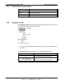
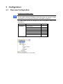
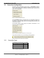
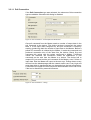
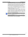
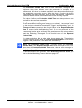
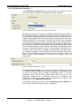
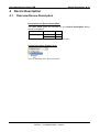
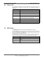
Operating Instruction Manual
Generic DTM for DeviceNet Slave Devices
Configuration of DeviceNet Slave Devices
Language: English
www.hilscher.com
Table of Contents • 2
DeviceNet Generic Slave DTM
Table of Contents
1
INTRODUCTION.........................................................................................................4
1.1
About this Manual .......................................................................................................4
1.1.1
1.1.2
1.1.3
1.2
Legal Notes.................................................................................................................7
1.2.1
1.2.2
1.2.3
1.2.4
1.2.5
1.2.6
1.3
Configuration Steps ..................................................................................................17
2.1.1
3.1
Overview Configuration ............................................................................................19
3.2
General Settings .......................................................................................................20
3.3
Connection Configuration .........................................................................................21
3.4
5
Configuring Device Parameters .........................................................................18
CONFIGURATION ....................................................................................................19
3.3.1
3.3.2
4
General Device Information................................................................................12
Navigation Area ..................................................................................................12
Dialog Panes ......................................................................................................13
Controls and Dialog Buttons...............................................................................14
Status Bar...........................................................................................................15
GETTING STARTED.................................................................................................17
2.1
3
Requirements .....................................................................................................10
Dialog Structure of the Generic DeviceNet Slave DTM ............................................11
1.4.1
1.4.2
1.4.3
1.4.4
1.4.5
2
Copyright ..............................................................................................................7
Important Notes ....................................................................................................7
Exclusion of Liability .............................................................................................8
Warranty ...............................................................................................................8
Export Regulations ...............................................................................................9
Registered Trademarks........................................................................................9
About Generic DeviceNet Slave DTM ......................................................................10
1.3.1
1.4
Online Help...........................................................................................................4
List of Revisions ...................................................................................................5
Conventions in this Manual ..................................................................................6
Connection Types...............................................................................................21
Watchdog Timeout Action ..................................................................................28
Parameter .................................................................................................................29
DEVICE DESCRIPTION ...........................................................................................30
4.1
Overview Device Description....................................................................................30
4.2
Device Info................................................................................................................31
4.3
EDS Viewer ..............................................................................................................31
LISTS ........................................................................................................................32
5.1
List of Figures ...........................................................................................................32
5.2
List of Tables ............................................................................................................33
Hilscher Gesellschaft für Systemautomation mbH – Rheinstr. 15 – D 65795 Hattersheim
Edition 5 – Oi:DTMDNGS#EN – 2009/01
DeviceNet Generic Slave DTM
Table of Contents • 3
6
GLOSSARY...............................................................................................................34
7
APPENDIX ................................................................................................................35
7.1
User Rights ...............................................................................................................35
7.1.1
Configuration ......................................................................................................36
7.2
References ...............................................................................................................37
7.3
Contacts....................................................................................................................38
Hilscher Gesellschaft für Systemautomation mbH – Rheinstr. 15 – D 65795 Hattersheim
Edition 5 – Oi:DTMDNGS#EN – 2009/01
Table of Contents • 4
DeviceNet Generic Slave DTM
1
Introduction
1.1
About this Manual
This manual describes how to configure DeviceNet Slave devices, which
are described with EDS files. These devices can be configured by use of
the Generic DeviceNet Slave DTM within a FDT Framework.
Dialog Panes
The table below gives an overview for the individual dialog panes
descriptions:
Section
Subsection
Manual
Page
Configuration
General Settings
20
Connection Configuration
21
Parameter
29
Device Info
31
EDS Viewer
31
Device Description
Table 1: Descriptions Dialog Panes
1.1.1
Online Help
The Generic DeviceNet Slave DTM contains an integrated online help
facility.
¾ To open the online help, click on the Help button or press the F1 key.
Hilscher Gesellschaft für Systemautomation mbH – Rheinstr. 15 – D 65795 Hattersheim
Edition 5 – Oi:DTMDNGS#EN – 2009/01
Table of Contents • 5
DeviceNet Generic Slave DTM
1.1.2
List of Revisions
Index
Date
1
2
Version
Component
Chapter Revisions
20/12/04 1.000
-
Alle
created
03/02/05 1.001
DevNetGenSlaveDTM.dll
Alle
revised
3
13/02/06 1.0.0.9
DevNetGenSlaveDTM.dll
1 bis 4
actualized
4
09.05.07 1.0.2.1,
1.0.1.2
DevNetGenSlaveDTM.dll
DeviceNetGenericSlaveDtm
Gui.ocx
1
2.1
3.1
Chapter ‚Introduction’ actualized,
Section ‚Overview Configuration’ actualized,
Section ‚Overview Device Description’
actualized,
Section ‚User Rights’ actualized,
Section ‚Contact’ added
Section ‚References’ added
4.1
4.2
4.3
5
07.01.09 1.0.4.0,
1.0.3.0
DevNetGenSlaveDTM.dll
DeviceNetGenericSlaveDtm
Gui.ocx
Alle
1
2
7.2
Manufacturer and product names generalized
(completed),
Chapter ’Introduction’ revised,
Chapter ’Getting started’ added
Section ‚User Rights’ revised,
Hilscher Gesellschaft für Systemautomation mbH – Rheinstr. 15 – D 65795 Hattersheim
Edition 5 – Oi:DTMDNGS#EN – 2009/01
DeviceNet Generic Slave DTM
1.1.3
Table of Contents • 6
Conventions in this Manual
Operation instructions, a result of an operation step or notes are marked as
follows:
Operation Instructions:
¾ <instruction>
Or
1. <instruction>
2. <instruction>
Results:
° <result>
Notes:
Note: <note>
<note were to find further information>
Hilscher Gesellschaft für Systemautomation mbH – Rheinstr. 15 – D 65795 Hattersheim
Edition 5 – Oi:DTMDNGS#EN – 2009/01
DeviceNet Generic Slave DTM
1.2
1.2.1
Table of Contents • 7
Legal Notes
Copyright
© 2008 Hilscher Gesellschaft für Systemautomation mbH
All rights reserved.
The images, photographs and texts in the accompanying material (user
manual, accompanying texts, documentation, etc.) are protected by
German and international copyright law as well as international trade and
protection provisions. You are not authorized to duplicate these in whole or
in part using technical or mechanical methods (printing, photocopying or
other methods), to manipulate or transfer using electronic systems without
prior written consent. You are not permitted to make changes to copyright
notices, markings, trademarks or ownership declarations. The included
diagrams do not take the patent situation into account. The company
names and product descriptions included in this document may be
trademarks or brands of the respective owners and may be trademarked or
patented. Any form of further use requires the explicit consent of the
respective rights owner.
1.2.2
Important Notes
The user manual, accompanying texts and the documentation were created
for the use of the products by qualified experts, however, errors cannot be
ruled out. For this reason, no guarantee can be made and neither juristic
responsibility for erroneous information nor any liability can be assumed.
Descriptions, accompanying texts and documentation included in the user
manual do not present a guarantee nor any information about proper use
as stipulated in the contract or a warranted feature. It cannot be ruled out
that the user manual, the accompanying texts and the documentation do
not correspond exactly to the described features, standards or other data of
the delivered product. No warranty or guarantee regarding the correctness
or accuracy of the information is assumed.
We reserve the right to change our products and their specification as well
as related user manuals, accompanying texts and documentation at all
times and without advance notice, without obligation to report the change.
Changes will be included in future manuals and do not constitute any
obligations. There is no entitlement to revisions of delivered documents.
The manual delivered with the product applies.
Hilscher Gesellschaft für Systemautomation mbH is not liable under any
circumstances for direct, indirect, incidental or follow-on damage or loss of
earnings resulting from the use of the information contained in this
publication.
Hilscher Gesellschaft für Systemautomation mbH – Rheinstr. 15 – D 65795 Hattersheim
Edition 5 – Oi:DTMDNGS#EN – 2009/01
DeviceNet Generic Slave DTM
1.2.3
Table of Contents • 8
Exclusion of Liability
The software was produced and tested with utmost care by Hilscher
Gesellschaft für Systemautomation mbH and is made available as is. No
warranty can be assumed for the performance and flawlessness of the
software for all usage conditions and cases and for the results produced
when utilized by the user. Liability for any damages that may result from the
use of the hardware or software or related documents, is limited to cases of
intent or grossly negligent violation of significant contractual obligations.
Indemnity claims for the violation of significant contractual obligations are
limited to damages that are foreseeable and typical for this type of contract.
It is strictly prohibited to use the software in the following areas:
• for military purposes or in weapon systems;
• for the design, construction, maintenance or operation of nuclear
facilities;
• in air traffic control systems, air traffic or air traffic communication
systems;
• in life support systems;
• in systems in which failures in the software could lead to personal injury
or injuries leading to death.
We inform you that the software was not developed for use in dangerous
environments requiring fail-proof control mechanisms. Use of the software
in such an environment occurs at your own risk. No liability is assumed for
damages or losses due to unauthorized use.
1.2.4
Warranty
Although the hardware and software was developed with utmost care and
tested intensively, Hilscher Gesellschaft für Systemautomation mbH does
not guarantee its suitability for any purpose not confirmed in writing. It
cannot be guaranteed that the hardware and software will meet your
requirements, that the use of the software operates without interruption and
that the software is free of errors. No guarantee is made regarding
infringements, violations of patents, rights of ownership or the freedom from
interference by third parties. No additional guarantees or assurances are
made regarding marketability, freedom of defect of title, integration or
usability for certain purposes unless they are required in accordance with
the law and cannot be limited. Warranty claims are limited to the right to
claim rectification.
Hilscher Gesellschaft für Systemautomation mbH – Rheinstr. 15 – D 65795 Hattersheim
Edition 5 – Oi:DTMDNGS#EN – 2009/01
DeviceNet Generic Slave DTM
1.2.5
Table of Contents • 9
Export Regulations
The delivered product (including the technical data) is subject to export or
import laws as well as the associated regulations of different counters, in
particular those of Germany and the USA. The software may not be
exported to countries where this is prohibited by the United States Export
Administration Act and its additional provisions. You are obligated to
comply with the regulations at your personal responsibility. We wish to
inform you that you may require permission from state authorities to export,
re-export or import the product.
1.2.6
Registered Trademarks
Windows® 2000/Windows® XP are registered trademarks of Microsoft
Corporation.
All other mentioned trademarks are property of their respective legal
owners.
Hilscher Gesellschaft für Systemautomation mbH – Rheinstr. 15 – D 65795 Hattersheim
Edition 5 – Oi:DTMDNGS#EN – 2009/01
DeviceNet Generic Slave DTM
1.3
Table of Contents • 10
About Generic DeviceNet Slave DTM
You can use the Generic DeviceNet Slave DTM to configure DeviceNet
Slave devices described with EDS files within a FDT Framework.
1.3.1
Requirements
System Requirements
• Windows® 2000/ Windows® XP
• CD ROM drive
• Graphic resolution: min. 1024 x 768 pixel
• Keyboard and Mouse
Requirements Generic DeviceNet Slave DTM
Requirements for working with a Generic DeviceNet Slave DTM are:
• Installed FDT/DTM V 1.2 compliant frame application
• Installed DeviceNet Master DTM
• EDS files of the devices to be configured
• The DTM must be loaded to the device catalog.
Loading EDS files
To work with the Generic DeviceNet Slave DTM, the EDS file of the device
must be present in the EDS folder in the installation directory of the DTM.
Hilscher Gesellschaft für Systemautomation mbH – Rheinstr. 15 – D 65795 Hattersheim
Edition 5 – Oi:DTMDNGS#EN – 2009/01
Table of Contents • 11
DeviceNet Generic Slave DTM
1.4
Dialog Structure of the Generic DeviceNet Slave DTM
The graphical user interface of the DTM is composed of different areas and
elements listed hereafter:
1. A header area containing the General Device Information,
2. The Navigation Area (area on the left side),
3. The Dialog Pane (main area on the right side),
4. The general buttons OK, Cancel, Apply, Help,
5. The Status Line containing information e. g. the online-state of the
DTM.
General Device Information
Navi
gation
Dialog Pane
Area
OK
Cancel
Apply
Help
Status Line
Figure 1: Dialog Structure of Generic DeviceNet Slave DTM
Hilscher Gesellschaft für Systemautomation mbH – Rheinstr. 15 – D 65795 Hattersheim
Edition 5 – Oi:DTMDNGS#EN – 2009/01
Table of Contents • 12
DeviceNet Generic Slave DTM
1.4.1
General Device Information
Parameter
Meaning
IO Device
Name of the device
Vendor
Vendor name of the device
Device ID
Identification number of the device
Vendor ID
Identification number of the vendor
Table 2: General Device Information
1.4.2
Navigation Area
The Navigation Area at the left side of the dialog provides a tree structure
to navigate through the panes of the DTM.
Figure 2: Navigation Area
¾ To access a DTM pane select the respective item of the navigation tree
structure.
The Navigation Area can be hidden or it can be displayed again.
Control
Meaning
Window button to hide the navigation area,
(at the right side of the navigation title bar).
Show navigation area button to open the navigation
area,
(at the lower left corner of the dialog pane).
Table 3: Hide / display Navigation
Hilscher Gesellschaft für Systemautomation mbH – Rheinstr. 15 – D 65795 Hattersheim
Edition 5 – Oi:DTMDNGS#EN – 2009/01
Table of Contents • 13
DeviceNet Generic Slave DTM
1.4.3
Dialog Panes
At the dialog pane the Settings or Device Description panes are opened
via the corresponding folder in the navigation area.
Configuration
General
On the page General Settings the MAC-ID can be read and the
parameters ’UCMM ’, ’Fragmentation Timeout’ or ’Verify Device
ID’ can be preset. Further information to this you find in section
General Settings on page 20.
…Connection
On the page Connection Configuration a connection type can
be selected and configured. Further information to this you find in
section Connection Configuration on page 21.
Parameters
In the Parameter dialog the parameter data of the device can be
edited. A detailed description you find in section Parameter on
page 29.
Device Description
Device
The Device Info pane contains the manufacturer information
about the device. For further information see section Device Info
on page 31.
EDS
By use of the EDS-Viewer an EDS file can be viewed and
searched through. For further information see section EDS
Viewer on page 31.
Table 4: Overview Dialog Panes
Hilscher Gesellschaft für Systemautomation mbH – Rheinstr. 15 – D 65795 Hattersheim
Edition 5 – Oi:DTMDNGS#EN – 2009/01
Table of Contents • 14
DeviceNet Generic Slave DTM
1.4.4
Controls and Dialog Buttons
In this section, you will find general information on controls and buttons.
1.4.4.1
General Buttons
The table below explains the general buttons in the DTM user interface.
Button
Meaning
OK
To confirm your latest settings, click on the OK button. All changed values
will be applied on the frame application database.
The dialog then closes.
Cancel
To cancel your latest changes, click on the Cancel button.
Answer to the safety query Configuration data has been changed. Do
you want to save the data? by Yes, No or Cancel.
Yes: The changes are saved or the changed values are applied on the
frame application database.
The dialog then closes.
No: The changes are not saved or the changed values are not applied on
the frame application database.
The dialog then closes.
Cancel: Back to the DTM.
Apply
To confirm your latest settings, click on the Apply button. All changed
values will be applied on the frame application database.
The dialog remains opened.
Help
To open the DTM online help, click on the Help button.
Table 5: General Buttons
1.4.4.2
Table Line Buttons
¾ To select, create or delete a line in a table use the buttons shown in the
table below.
Button
Meaning
To select the first line of a table use the button First Line.
To select the previous line of a table use the button Previous Line.
To select the next line of a table use the button Next Line.
To select the last line of a table use the button Last Line.
The button Create a new Line inserts new lines into the table.
The button Delete selected Line deletes the selected line from the table.
Table 6: Table Line – Buttons
Hilscher Gesellschaft für Systemautomation mbH – Rheinstr. 15 – D 65795 Hattersheim
Edition 5 – Oi:DTMDNGS#EN – 2009/01
Table of Contents • 15
DeviceNet Generic Slave DTM
1.4.5
Status Bar
The Status Bar displays information about the current state of the DTM.
The current activity e.g. download is signaled graphically via icons in the
status bar.
Figure 3: Status Bar – Status Fields 1 to 6
Status
Field
Icon / Meaning
1
DTM Connection States
Connecting: Icon going closed = Device is going online
Connected: Icon closed = Device is online
Disconnecting: Icon going opened = Device is going offline
Disconnected: Icon opened = Device is offline
Disconnected – disturbed: Icon with lightening = Device
communication disturbed
2
Data Source States
Data set: The displayed data are read out from the instance data set
(database).
Data set locked: The displayed data are read out from the instance data
set (database). Database is locked with password.
Device: The displayed data are read out from the device.
Device locked: The displayed data are read out from the device.
Device is locked with password.
3
States of the instance Date Set
-
All data loaded
Valid Modified: Parameter is changed (not equal to data source).
Invalid Modified: Invalid value (e. g. not plausible).
4
Initial data set: Parameter value is equal to data source value (data
base or field device).
Changes directly made on the Device
Changes have only an impact on the device and not on the instance data
set. Instance data set and the device may not be consistent any more.
Load/configure diagnosis parameters: Diagnosis is activated.
5
Direct Mode active
Direct Mode active
More see next page
Hilscher Gesellschaft für Systemautomation mbH – Rheinstr. 15 – D 65795 Hattersheim
Edition 5 – Oi:DTMDNGS#EN – 2009/01
Table of Contents • 16
DeviceNet Generic Slave DTM
Status
Field
Icon / Meaning
6
Device Diagnosis Status
Device Failure: Incorrect communication due to malfunction in the field
device or its peripherals.
Maintenance required: Although the communication is error-free, the
wear reserve is nearly exhausted or a function will soon be restricted
due to operational conditions.
Off-specification: The device is operating outside its specified range or
internal diagnosis indicates deviations from measured or set values due
to internal problems in the device or process characteristics.
Device OK: Communication is error-free.
Functional Check: Communication temporarily incorrect (e.g. frozen)
due to on-going work on the device.
Diagnosis deactivated
Table 7: Status Bar Icons [1]
Hilscher Gesellschaft für Systemautomation mbH – Rheinstr. 15 – D 65795 Hattersheim
Edition 5 – Oi:DTMDNGS#EN – 2009/01
DeviceNet Generic Slave DTM
2
2.1
Table of Contents • 17
Getting Started
Configuration Steps
The following table describes the steps to configure a device with the
Generic DeviceNet Slave DTM as it is typical for many cases. At this time it
is presupposed that the DeviceNet Master DTM installation was already
done.
#
Step
Short Description
1
Add DeviceNet Slave in
the Device Catalog
Add the Device in the Device Catalog by importing
the device description file to the Device Catalog.
Depending of the FDT Container.
For netDevice:
- Network > Import Device Descriptions.
Load device catalog
Depending of the FDT Container:
For netDevice:
- select Network > Device Catalog,
- select button Reload Catalog.
2
3
4
5
Create new project /
Open existing project
Depending of the frame application.
For the configuration software:
- select File > New or File > Open.
Insert Controller or
Depending of the FDT Container:
Device into configuration For netDevice:
- in the Device Catalog click to the Controller,
- and insert the device via drag and drop
to the line in the network view,
- in the Device Catalog click to the Device,
- and insert the device via drag and drop
to the Controller bus line in the network view.
Configure Device
For detailed information see Page
section
(See User Manual netDevice
and netProject)
(See User Manual netDevice
and netProject)
(See User Manual of the
Frame Application)
(See User Manual of the
Frame Application)
Configure the Device.
- Double click to the device icon of the Device.
- The Generic Device DTM configuration dialog is
displayed.
In the Generic Device DTM configuration dialog:
- select Configuration >General,
- set UCMM and Fragmentation Timeout,
- select Configuration > Connection,
- configure the device connection,
- select Configuration >Parameter,
- set the parameter data of the device,
- close the Generic Device DTM configuration
dialog via the button OK.
Configuring Device
Parameters
18
General Settings
20
Connection Configuration
21
Parameter
29
-
6
Configuration Steps
Controller device
Configure the Controller device via DeviceNet
Master DTM.
(See User Manual DTM for
DeviceNet Master devices)
7
Save project
Depending of the frame application.
For the configuration software:
- select File > Save.
(See User Manual of the
Frame Application)
-
Table 8: Getting Started - Configuration Steps
For information to further steps as Download Configuration or
Diagnosis, refer to the user manual DTM for DeviceNet Master devices.
Hilscher Gesellschaft für Systemautomation mbH – Rheinstr. 15 – D 65795 Hattersheim
Edition 5 – Oi:DTMDNGS#EN – 2009/01
DeviceNet Generic Slave DTM
2.1.1
Getting Started • 18
Configuring Device Parameters
The following steps are needed to configure the device parameters using
the Generic DeviceNet Slave DTM:
1. Set UCMM and Fragmentation Timeout.
¾ Select Configuration > General in the navigation area.
2. Configure the device connection.
¾ Select Configuration > Connection in the navigation area.
3. Set the parameter data of the device.
¾ Select Configuration > Parameter in the navigation area.
For more information refer to section General Settings on page 20,
Connection Configuration on page 21 and Parameter on page 29.
Hilscher Gesellschaft für Systemautomation mbH – Rheinstr. 15 – D 65795 Hattersheim
Edition 5 – Oi:DTMDNGS#EN – 2009/01
3
3.1
Configuration
Overview Configuration
Configuration Dialog Panes
Note: Access to the configuration panes is enabled without requirement
of user rights. However for editing certain user rights are required. Further
information can be found in section and User Rights on page 35.
The table below gives an overview for the Configuration dialog panes
descriptions:
Section
Subsection
Page
Configuration
General Settings
20
Connection Configuration
21
Poll Connection
22
Change of State Connection
24
Cyclic Connection
26
Bit-Strobe Connection
27
Parameter
Table 9: Descriptions of the Configuration Dialog Panes
Figure 4: Navigation Area - Configuration
29
DeviceNet Generic Slave DTM
3.2
Configuration • 20
General Settings
The Dialog General Settings contains the following configuration
possibilities:
Figure 5: General Settings - Attributes of the device identification
Parameter
Meaning
Range of Value
MAC ID
The MAC ID is assigned by the Master and can not be edited here.
Changing the MAC ID has to be made with the DeviceNet Master
DTM.
0 … 63
With each device inserted into the configuration the MAC ID is
increased automatically by one.
UCMM
If the field UCMM is selected, the device is used as UCMMcompatible device.
The option UCMM is used for devices which need the UCMM
message format. Group 1, 2 and 3 are supported. The
documentation of the used device gives information whether this
option is to be used or not.
Fragmentation Fragmentation Timeout (Expl. Message Timeout): If an IO data
Timeout
transmission or an Explicit Message is larger than 8 byte, this must
be transferred fragmented in the DeviceNet (in several telegrams).
Group1,
Group2,
Group3
0 … 1700 … 65535
The Fragmentation Timeout specifies, how long the Master waits,
until a Slave answers a fragmented telegram.
Note: Small values can lead to communication disturbances.
Table 10: General Settings - Attributes of the device identification
Figure 6: General Settings - Verify Device ID
The function Verify Device ID compares the device description in the EDS
file of the device with the existing hardware, if the device characteristics of
the EDS file agree with those of the hardware.
The check is made for the selected attributes in each case.
Hilscher Gesellschaft für Systemautomation mbH – Rheinstr. 15 – D 65795 Hattersheim
Edition 5 – Oi:DTMDNGS#EN – 2009/01
Configuration • 21
DeviceNet Generic Slave DTM
3.3
Connection Configuration
DeviceNet allows establishing several kinds of Connections between
devices. In DeviceNet a device (Slave) is mapped as a collection of objects.
These objects communicate via different connection types, which you can
adjust under Connection.
Figure 7: Configuration Dialog Connection
In the Connection dialog a connection type or a combination of types can
be selected. Please note that a device has not to support all types of IO
connections. Connection types which are not supported by the device are
automatically disabled.
In the lower section of this dialog the possible combinations of the
connection types are displayed:
Figure 8: Indication of possible combinations of connection types
If an invalid combination is set, the following warning appears:
Figure 9: Warning invalid connection type combination
3.3.1
Connection Types
The following connection types are available:
Connection Type
Page
Poll Connection
22
Change of State Connection
24
Cyclic Connection
26
Bit-Strobe Connection
27
Table 11: Possible connection types
Hilscher Gesellschaft für Systemautomation mbH – Rheinstr. 15 – D 65795 Hattersheim
Edition 5 – Oi:DTMDNGS#EN – 2009/01
3.3.1.1 Poll Connection
If the Poll Connection type was activated, the elements of this connection
type are editable. Otherwise this dialog is disabled.
Figure 10: Poll Connection - Consumption and Production
One poll command from the Master sends a number of output data in the
poll command to the device. The device receives (consumes) the output
data. If it has input data configured for this poll connection it reacts by
sending (producing) back the number of input data to the Master. Before a
polled I/O connection is initiated by the Master, it reads the consumed and
produced connection size of the data from the device (Slave) first and
compares this values with the values configured in Master. If different
values are detected, the connection cannot be established. A poll
command can be sent from the Master to a device. The device has to
respond if it has received the poll command of the Master, even if it has no
input data. Else the Master will report a timeout error. Polling data to many
devices has the disadvantage that the network traffic rate is very high and
most data which is transferred has not changed since the last transmission.
Furthermore the higher the bus load more communication errors can occur
if the bus is disturbed by external influences.
Figure 11: Poll Connection – Timing
DeviceNet Generic Slave DTM
Configuration • 23
The Production Inhibit Time, one for each connection, configures the
minimum delay time between new data production in multiples of a
millisecond. The timer is reloaded each time new data production through
the established connection occurs. While the timer is running the device
suppresses new data production until the timer has expired. This method
prevents that the device is overloaded with to fast incoming requests.
The value 0 defines no Production Inhibit Time and data production can
and will be done as fast as possible. If in polled mode for example a
Production Inhibit Time of 1000 ms is configured, then the poll request
message to the device will be sent every second.
The Expected Packet Rate, one for each connection, is always transferred
to the device before starting and doing the I/O transfer. The fourfold value
is used by the device later to reload its 'Watchdog Timer'. If no data
production of the remote station takes place within this time, so the
connection changes into a watchdog timeout error. Incoming data
productions of the remote station load the Watchdog Time again to the
fourfold value of the Expected Packet Rate.
Note: the Production Inhibit Time is verified against the Expected
Packet Rate. If the Expected Packet Rate value is unequal to zero, but
less than the Production Inhibit Time value, then an error message is
displayed by the application.
A description about the pull-down menu Watchdog Timeout Action you
find in section Watchdog Timeout Action on page 28.
Hilscher Gesellschaft für Systemautomation mbH – Rheinstr. 15 – D 65795 Hattersheim
Edition 5 – Oi:DTMDNGS#EN – 2009/01
DeviceNet Generic Slave DTM
Configuration • 24
3.3.1.2 Change of State Connection
If the Change of State Connection type was activated, the elements of
this connection type are editable. Otherwise this dialog is disabled.
Figure 12: Change of State Connection - Consumption and Production
With this type of connection both Master and Slave send the configured
amount of data (max. 255 Byte) to the respective remote station. This data
production is started at change in value (trigger). If the data production
does not take place during a defined time interval, the devices trigger the
data production automatically to load the Watchdog Timer of the connection
again. Depending on how the device behavior is configured, they can send
back a confirmation message which contains any quantity of data and/or
status information. Before a Change of State connection is initialized by
the Master, it reads out the consumed and produced connection size of the
data from the device (Slave) and compares this values with the values
configured in the Master during configuration. If different values are
determined, the connection can not build up. Data production only over
'Change of State' keeps the bus load as low as possible, while data than
can be transmitted as fast as possible by each device because bus
conflicts are less possible. So you can get high performance data
transmission with in comparison low baud rates.
Figure 13: Change of State Connection – Timing
Hilscher Gesellschaft für Systemautomation mbH – Rheinstr. 15 – D 65795 Hattersheim
Edition 5 – Oi:DTMDNGS#EN – 2009/01
DeviceNet Generic Slave DTM
Configuration • 25
The Production Inhibit Time, one for each connection, configures the
minimum delay time between new data production in multiples of a
millisecond. The timer is reloaded each time new data production through
the established connection occurs. While the timer is running the device
suppresses new data production until the timer has expired. This method
prevents that the device is overloaded with to fast incoming requests.
The value 0 defines no Production Inhibit Time and data production can
and will be done as fast as possible.
The Expected Packet Rate, one for each connection, is always transferred
to the device before starting and doing the I/O transfer. The value is used
by the device to reload its 'Transmission Trigger' and 'Watchdog Timer'. In
Change of State connections the fourfold value of the Expected Packet
Rate is used to build the 'Watchdog Timer'. If no data production of the
remote station takes place within this time, so the connection changes into
a watchdog timeout error. Incoming data productions of the remote station
load the Watchdog Time again to the fourfold value of the Expected
Packet Rate.
If a data production did not take place since starting the 'Transmission
Trigger Timer' as single values of the Expected Packet Rate, so the device
triggers a data production at the latest then automatically.
Note: the Production Inhibit Time is verified against the Expected
Packet Rate. If the Expected Packet Rate value is unequal to zero, but
less than the Production Inhibit Time value, then an error message is
displayed by the application.
A description about the pull-down menu Watchdog Timeout Action you
find in section Watchdog Timeout Action on page 28.
Hilscher Gesellschaft für Systemautomation mbH – Rheinstr. 15 – D 65795 Hattersheim
Edition 5 – Oi:DTMDNGS#EN – 2009/01
DeviceNet Generic Slave DTM
Configuration • 26
3.3.1.3 Cyclic Connection
If the Cyclic Connection type was activated, the elements of this
connection type are editable. Otherwise this dialog is disabled.
Figure 14: Cyclic Connection - Consumption and Production
At this transmission type a data production takes place automatically, if the
'Transmission Trigger Timer' has expired as single value of the Expected
Packet Rate.
Figure 15: Cyclic Connection - Timing
The Expected Packet Rate, one for each connection, is always transferred
to the device before starting and doing the I/O transfer. The value is used
by the device to reload its 'Transmission Trigger' and 'Watchdog Timer'. In
Cyclic connections the fourfold value of the Expected Packet Rate is used
to reload the 'Transmission Trigger Timer' and the 'Watchdog Timer'. If no
data production of the remote station takes place within this time, so the
connection changes into a watchdog timeout error. Incoming data
productions of the remote station load the Watchdog Time again to the
fourfold value of the Expected Packet Rate.
A description about the pull-down menu Watchdog Timeout Action you
find in section Watchdog Timeout Action on page 28.
Hilscher Gesellschaft für Systemautomation mbH – Rheinstr. 15 – D 65795 Hattersheim
Edition 5 – Oi:DTMDNGS#EN – 2009/01
DeviceNet Generic Slave DTM
Configuration • 27
3.3.1.4 Bit-Strobe Connection
If the Bit-Strobe Connection type was activated, the elements of this
connection type are editable. Otherwise this dialog is disabled.
Figure 16: Bit-Strobe Connection - Consumption and Production
Bit strobe command and response messages rapidly move small amounts
of output data between the Master device and one/some/all Slave devices.
The bit strobe message contains a bit string of 64 bits of output data, one
output bit per possible device. Each bit in there is assigned to one device
address (MAC-ID) in the network. Herewith this service has broadcast
functionality that means more than one Slave device can be addressed by
one command. Because all addressed Slave devices get this command at
the same time, this command is normally used to synchronize data transfer
to several Slave devices. A Slave device can take its corresponding output
bit as a real output information to give it to the peripheral connections (e.g.
an LED) and/or use the bit as a trigger to send back its input data with a
poll response message. The data that can be sent back from each Slave
after a bit strobe command was received is limited to 8 bytes in length. Bit
strobe usage causes therefore a reduced bus loading than poll
connections.
Figure 17: Bit-Strobe Connection - Timing
The Expected Packet Rate, one for each connection, is always transferred
to the device before starting and doing the I/O transfer. The fourfold value
is used by the device later to reload its 'Watchdog Timer'. If no data
production of the remote station takes place within this time, so the
connection changes into a watchdog timeout error. Incoming data
productions of the remote station load the Watchdog Time again to the
fourfold value of the Expected Packet Rate.
A description about the pull-down menu Watchdog Timeout Action you
find in section Watchdog Timeout Action on page 28.
Hilscher Gesellschaft für Systemautomation mbH – Rheinstr. 15 – D 65795 Hattersheim
Edition 5 – Oi:DTMDNGS#EN – 2009/01
DeviceNet Generic Slave DTM
3.3.2
Configuration • 28
Watchdog Timeout Action
The Watchdog Timeout Action defines the device behavior when the
watchdog timer in the device (Slave) expires. The following actions are
adjustable:
• Timeout: The connection transitions to the timeout state and remains in
this state until it is Reset or Deleted.
• Auto delete: The connection class automatically deletes the connection
if it experiences an Inactivity/Watchdog timeout.
• Auto reset: The connection remains in the established state and
immediately restarts the Inactivity/Watchdog timer.
Hilscher Gesellschaft für Systemautomation mbH – Rheinstr. 15 – D 65795 Hattersheim
Edition 5 – Oi:DTMDNGS#EN – 2009/01
Configuration • 29
DeviceNet Generic Slave DTM
3.4
Parameter
In the Parameter dialog the parameter data of the device can be edited.
If default parameters are configured in the EDS file for this device, these
are inserted automatically. Some of devices need further parameterization
data, to change for example a measurement limitation or a value range.
These data are device specific and their functionality can not be explained
at this point. The explanation can be found in the corresponding device
manual.
Figure 18: Parameter Configuration
Parameter
Value
Description
Parameter Group
ALL
All parameter groups defined in the EDS file are merged in one
table.
USER DEFINED
A parameter group defined by the user is displayed.
xxx
In the EDS file of the device further parameter groups can be
defined, which are also displayed in the pull-down menu Parameter
Group. The name of this parameter group itself is also defined in
the EDS file.
Decimal
The values Min and Max in the table are indicated in decimal
notation by default. By selecting the Display Mode Hexadecimal
the values are shown in hexadecimal notation.
Display Mode
Hexadecimal
Table 12: Change Parameter Data
By using a data set the respective parameter value for the Master
configuration are approved and transferred to the Slave by the Master
during the initialization phase.
A description of the individual parameters, indicated by Class, Instance
and Attribute, can be refered in the device description of the manufacturer.
If “User Defined” is selected in Parameter Group, the entries in the
columns Param. Name and Value are editable. Otherwise the entries are
fixed and can not be changed.
Hilscher Gesellschaft für Systemautomation mbH – Rheinstr. 15 – D 65795 Hattersheim
Edition 5 – Oi:DTMDNGS#EN – 2009/01
Device Description • 30
DeviceNet Generic Slave DTM
4
4.1
Device Description
Overview Device Description
Descriptions of “Device Description”
The table below gives an overview for the Device Description dialog
panes descriptions:
Section
Subsection
Page
Device Description
Device Info
31
EDS Viewer
31
Table 13: Descriptions of the Dialog Panes Device Description
Device Description Dialog Panes
Figure 19: Navigation Area - Device Description
Hilscher Gesellschaft für Systemautomation mbH – Rheinstr. 15 – D 65795 Hattersheim
Edition 5 – Oi:DTMDNGS#EN – 2009/01
Device Description • 31
DeviceNet Generic Slave DTM
4.2
Device Info
The Device Info dialog contains manufacturer information about the
device, which is defined in the EDS file. The following information is
indicated:
Parameter
Meaning
Vendor name
Vendor name of the device
Vendor ID
Identification number of the manufacturer
Product Type
Communication Adapter
Product Type String
Product Name as string
Product Code
Product code of the device
Product Name
Name of the device
The variable Product Name is a text string that should represent
a short description of the product/product family.
Major Revision
Major Revision
Minor Revision
Minor Revision
Catalog
Used catalog name
Icon filei
Udes icon file name
Table 14: General Device Information
4.3
EDS Viewer
The EDS Viewer shows the content of the EDS file in a text view.
Under Filename the file directory path and the file name of the displayed
EDS file is displayed. Find what offers a search feature to search for text
contents within the text of the EDS file.
In the EDS Viewer window on the left side, the line number is displayed for
simple overview, the further entries show the EDS file in text format.
Parameter
Meaning
Filename
File directory path and the file name of the displayed EDS file.
Find what
Search feature to search for text contents within the text of the
EDS file.
Match case
Search option
Match whole word
Search option
Table 15: Device Description – EDS Viewer
Hilscher Gesellschaft für Systemautomation mbH – Rheinstr. 15 – D 65795 Hattersheim
Edition 5 – Oi:DTMDNGS#EN – 2009/01
DeviceNet Generic Slave DTM
5
5.1
Lists • 32
Lists
List of Figures
Figure 1: Dialog Structure of Generic DeviceNet Slave DTM
Figure 2: Navigation Area
Figure 3: Status Bar – Status Fields 1 to 6
Figure 4: Navigation Area - Configuration
Figure 5: General Settings - Attributes of the device identification
Figure 6: General Settings - Verify Device ID
Figure 7: Configuration Dialog Connection
Figure 8: Indication of possible combinations of connection types
Figure 9: Warning invalid connection type combination
Figure 10: Poll Connection - Consumption and Production
Figure 11: Poll Connection – Timing
Figure 12: Change of State Connection - Consumption and Production
Figure 13: Change of State Connection – Timing
Figure 14: Cyclic Connection - Consumption and Production
Figure 15: Cyclic Connection - Timing
Figure 16: Bit-Strobe Connection - Consumption and Production
Figure 17: Bit-Strobe Connection - Timing
Figure 18: Parameter Configuration
Figure 19: Navigation Area - Device Description
Hilscher Gesellschaft für Systemautomation mbH – Rheinstr. 15 – D 65795 Hattersheim
Edition 5 – Oi:DTMDNGS#EN – 2009/01
11
12
15
19
20
20
21
21
21
22
22
24
24
26
26
27
27
29
30
DeviceNet Generic Slave DTM
5.2
Lists • 33
List of Tables
Table 1: Descriptions Dialog Panes
Table 2: General Device Information
Table 3: Hide / display Navigation
Table 4: Overview Dialog Panes
Table 5: General Buttons
Table 6: Table Line – Buttons
Table 7: Status Bar Icons [1]
Table 8: Getting Started - Configuration Steps
Table 9: Descriptions of the Configuration Dialog Panes
Table 10: General Settings - Attributes of the device identification
Table 11: Possible connection types
Table 12: Change Parameter Data
Table 13: Descriptions of the Dialog Panes Device Description
Table 14: General Device Information
Table 15: Device Description – EDS Viewer
Table 16: User Rights - General Settings (D = Displaying, X = Editing, Configuring)
Table 17: User Rights – Connection (D = Displaying, X = Editing, Configuring)
Table 18: User Rights – Parameter (D = Displaying, X = Editing, Configuring)
Hilscher Gesellschaft für Systemautomation mbH – Rheinstr. 15 – D 65795 Hattersheim
Edition 5 – Oi:DTMDNGS#EN – 2009/01
4
12
12
13
14
14
16
17
19
20
21
29
30
31
31
36
36
37
DeviceNet Generic Slave DTM
6
Glossary • 34
Glossary
DTM
Device Type Manager
The Device Type Manager (DTM) is a software module with grafical user
interface for the configuration and/or for diagnosis of devices.
EDS
An Electronic Data Sheet (EDS) provides information necessary to access
and alter the configurable parameters of a device. An Electronic Data Sheet
(EDS) is an external file that contains information about configurable
attributes for the device, including object addresses of each parameter. The
application objects in a device represent the destination addresses for
configuration data. These addresses are encoded in the EDS.
FDT
Field Device Tool
FDT specifies an interface, in order to be able to use DTM (Device Type
Manager) in different applications of different manufacturers.
MAC ID
The network address of a device serves to distinguish itself on a DeviceNet
fieldbus system from any other device or Slave on this network. This should
be a unique number for each device.
Hilscher Gesellschaft für Systemautomation mbH – Rheinstr. 15 – D 65795 Hattersheim
Edition 5 – Oi:DTMDNGS#EN – 2009/01
DeviceNet Generic Slave DTM
7
7.1
Appendix • 35
Appendix
User Rights
User-rights are set within the FDT-container. Depending on the level the
configuration is accessible by the user or read-only.
To access the Configuration and Device Description panes of the
Generic DeviceNet Slave DTM you do not need special user rights.
Note: To edit, set or configure the parameters of the Configuration
panes, you need user rights for Maintenance, for Planning Engineer or for
Administrator.
The Device Description panes do not contain any editable elements. The
indicated values in are only for information purposes.
The following tables give an overview of the user right groups and which
user rights you need to configure the single parameters.
Hilscher Gesellschaft für Systemautomation mbH – Rheinstr. 15 – D 65795 Hattersheim
Edition 5 – Oi:DTMDNGS#EN – 2009/01
Appendix • 36
DeviceNet Generic Slave DTM
Configuration
Observer
Operator
Maintenance
Planning
Engineer
Administrator
General Settings
General Settings
X
X
X
X
X
UCMM support
D
D
X
X
X
Fragmentation Timeout
D
D
X
X
X
Verify Device Key
X
X
X
X
X
Table 16: User Rights - General Settings (D = Displaying, X = Editing, Configuring)
Operator
Maintenance
Planning
Engineer
Administrator
Connection
Observer
7.1.1
X
X
X
X
X
Poll Connection (*)
X
X
X
X
X
Change of State Connection (*)
X
X
X
X
X
Cyclic Connection (*)
X
X
X
X
X
Bit-Strobe Connection (*)
X
X
X
X
X
Connection Configuration
Note (*): The user rights for setting the individual elements of the selected connection type
is described in the following table section:
EDS Default Values Button
D
D
X
X
X
Length
D
D
X
X
X
Connection Path
D
D
X
X
X
Path description
D
D
X
X
X
Production Inhibit Time
D
D
X
X
X
Expected Packet Rate
D
D
X
X
X
Watchdog Timeout Action
D
D
X
X
X
Table 17: User Rights – Connection (D = Displaying, X = Editing, Configuring)
Hilscher Gesellschaft für Systemautomation mbH – Rheinstr. 15 – D 65795 Hattersheim
Edition 5 – Oi:DTMDNGS#EN – 2009/01
Appendix • 37
DeviceNet Generic Slave DTM
Observer
Operator
Maintenance
Planning
Engineer
Administrator
Parameter
X
X
X
X
X
Parameter Group
X
X
X
X
X
Display Mode
D
D
X
X
X
Navigation buttons
X
X
X
X
X
Add/Delete buttons
D
D
X
X
X
EDS Default Values button
D
D
X
X
X
Parameter
Table 18: User Rights – Parameter (D = Displaying, X = Editing, Configuring)
7.2
References
[1]
Device Type Manager (DTM) Style Guide, Version 1.0 ; FDT-JIG - Order No.
<0001-0008-000>
Hilscher Gesellschaft für Systemautomation mbH – Rheinstr. 15 – D 65795 Hattersheim
Edition 5 – Oi:DTMDNGS#EN – 2009/01
Appendix • 38
DeviceNet Generic Slave DTM
7.3
Contacts
Headquarter
Germany
Hilscher Gesellschaft für
Systemautomation mbH
Rheinstrasse 15
65795 Hattersheim
Phone: +49 (0) 6190 9907-0
Fax: +49 (0) 6190 9907-50
E-Mail: [email protected]
Support
Phone: +49 (0) 6190 9907-99
E-Mail: [email protected]
Subsidiaries
China
Japan
Hilscher Ges.f.Systemaut. mbH
Shanghai Representative Office
200010 Shanghai
Phone: +86 (0) 21-6355-5161
E-Mail: [email protected]
Hilscher Japan KK
Tokyo, 160-0022
Phone: +81 (0) 3-5362-0521
E-Mail: [email protected]
Support
Phone: +81 (0) 3-5362-0521
E-Mail: [email protected]
Phone: +86 (0) 21-6355-5161
E-Mail: [email protected]
Support
Switzerland
France
Hilscher France S.a.r.l.
69500 Bron
Phone: +33 (0) 4 72 37 98 40
E-Mail: [email protected]
Support
Phone: +33 (0) 4 72 37 98 40
E-Mail: [email protected]
Hilscher Swiss GmbH
4500 Solothurn
Phone: +41 (0) 32 623 6633
E-Mail: [email protected]
Support
Phone: +49 (0) 6190 9907-99
E-Mail: [email protected]
USA
Italy
Hilscher Italia srl
20090 Vimodrone (MI)
Phone: +39 02 25007068
E-Mail: [email protected]
Support
Phone: +39 / 02 25007068
E-Mail: [email protected]
Hilscher North America, Inc.
Lisle, IL 60532
Phone: +1 630-505-5301
E-Mail: [email protected]
Support
Phone: +1 630-505-5301
E-Mail: [email protected]
Hilscher Gesellschaft für Systemautomation mbH – Rheinstr. 15 – D 65795 Hattersheim
Edition 5 – Oi:DTMDNGS#EN – 2009/01