1
audionet
PRE G2
Reference Pre-Amplifier
User's Manual
1
2
Contents
1
Preface ....................................................................... 5
1.1
Included ....................................................................................... 6
1.2
Transport..................................................................................... 6
2
Overview front panel ................................................ 7
3
Overview back panel ................................................ 8
4
Installation and power supply ................................. 9
4.1
Placement .................................................................................... 9
4.2
Mains connection ........................................................................ 9
4.3
Orientation of mains plug ........................................................ 10
4.4
Additional earth connection .................................................... 10
5
Inputs and outputs.................................................. 11
5.1
Inputs ......................................................................................... 11
5.2
Outputs ...................................................................................... 11
5.3
Recording devices ..................................................................... 12
5.4
Audionet Link ........................................................................... 12
6
Usage ....................................................................... 13
6.1
Powering up .............................................................................. 13
6.2
Switching on and off ................................................................. 13
6.3
Mains phase detection .............................................................. 14
6.4
Using Audionet Link ................................................................ 14
6.5
Control elements on the front panel ....................................... 15
6.6
Volume control.......................................................................... 15
6.7
Display ....................................................................................... 16
6.8
Input selection ........................................................................... 17
6.9
Muting ....................................................................................... 18
7
Setup Menu ............................................................. 19
7.1
Set Dim Level ............................................................................ 20
7.2
Balance Adjust .......................................................................... 21
7.3
Offset Adjust ............................................................................. 22
7.4
Set DC Servo ............................................................................. 23
3
7.5
Channel name ........................................................................... 24
7.6
Set Autostart ............................................................................. 24
7.7
Set Off-Text ............................................................................... 25
7.8
Set Channel for By-Pass Mode ................................................ 25
7.9
Set DC Servo for By-Pass M. ................................................... 28
7.10
Overview factory defaults ........................................................ 29
8
Audionet Metal Remote Control ............................ 30
8.1
Key assignment PRE G2 .......................................................... 31
8.2
Changing the batteries ............................................................. 31
8.3
Settings for Audionet preamplifier ......................................... 32
9
Technical information ............................................ 34
9.1
Design ........................................................................................ 34
9.2
Power supply ............................................................................. 34
9.3
Circuitry .................................................................................... 34
9.4
Handling .................................................................................... 35
9.5
Update PRE to PRE G2 ........................................................... 35
10
Security advice ....................................................... 36
11
Technical data ........................................................ 37
4
1
Preface
The Audionet Team congratulates you on your purchase of this unit.
Music lovers know about the importance of the pre amplifier: The pre
amplifier determines the sound quality. For those enthusiast we developed the PRE G2, our pre amplifier reference.
The PRE G2 is a luxurious source of pure sound. With the highest accuracy and resolution, coarse and fine dynamic precision and overwhelming
spatiality it reproduces music in all its naturalness.
The PRE G2 does not accept compromise. With fundamental scientific
research and elaborate development and trial, each detail was conceived
and tested. The circuitry is state-of-the-art, its design beyond all doubt
and all its components painstakingly selected.
As nothing else could satisfy our demands, we produce operational amplifiers, incremental encoder and signal cables ourselves. Volume is controlled by an electronically switched and in real-time linearized resistor
network made of discrete high quality metal film resistors. The audio
signal path and control circuitry are decoupled optically. Input and output
circuits are immune to negative influences of connected devices. Thus,
the PRE G2 manifests the limits of what is possible nowadays regarding
measuring techniques. Noise, distortion and crosstalk are almost eliminated.
A microprocessor facilitates versatile control functionality and highest
handling comfort. All information is delivered through a big vacuum
fluorescent display. Every function is supported by the remote control.
Never show the PRE G2 to other pre amplifiers! The will go green with
envy.
But before you start listening to your new Audionet PRE G2, please read
this manual carefully so you are able to use and enjoy all functions of this
unit without drawback on music quality.
5
1.1 Included
Included you will find the following items:
·
the reference pre amplifier PRE G2
·
the Audionet Metal Remote Control RC 1
·
the user's manual (that you are currently reading)
·
one standard power cord
·
one green-yellow cord for an additional earth connection
1.2 Transport
Important
·
Please transport the PRE G2 only in the included package.
·
Always use the provided cloth bag to prevent scratches on the casing.
·
Please allow the PRE G2 to adapt to the climatic conditions in your
listening room before you switch on the unit for the first time after
transport.
6
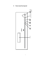
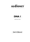
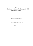
Display
PRE G2
mute
key
Stereo Preamplifier
set
key
set
input
key
mute
power
power
key
input
IR remote
volume knob
control recevier (incremental
encoder)
volume
2
Overview front panel
7
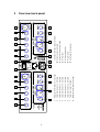
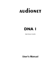
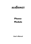
AC: 220/240 V
50/60 Hz
6
8
Cinch (line) input no. 3, left/right
Cinch (line) input no. 4, left/right
Cinch (line) input no. 5, left/right
Cinch (line) input no. 6, left/right
Cinch (line) output, left/right
Balanced (XLR) outputs, left/right
3
4
5
6
7
8
10
1
Cinch (line) input no. 2, left/right
9
2
2
8
3
Balanced (XLR) input no. 1, left/right
4
14
11
13
15
7
5
4
8
3
Inverted Cinch (line) output, left/right
gnd
6
15 Additional earth connector
14 Mains switch
13 Marking mains phase
12 Mains input
11 Outputs Audionet Link 1 and 2
10 Monitor output, left/right
9
12
phase
1
7
5
9
2
10
1
3
Overview back panel
4
Installation and power supply
Important
·
During connecting and removing of sources or amplifiers to the
PRE G2 all units of your audio system have to be switched off to
prevent damage of the PRE G2 or any of the other connected
units.
·
Please make sure that all cables are in absolute best conditions!
Broken shields or short-cut cables could damage the PRE G2
and/or any other connected unit.
4.1 Placement
Important
·
It is recommended to place the PRE G2 into a high quality rack or
onto a stable table.
·
Do not expose the unit to direct sunlight.
·
Do not place the PRE G2 in close range to heat sources like radiators.
·
Do not place the PRE G2 on top of other units, especially not on top
of power amplifiers, pre amplifiers or similar that produce heat. Both
units could suffer damage from thermal overload.
·
Do not use the unit in places where it is exposed to vibrations.
·
Do not place the unit close to loudspeakers or into the corner of a
room where it is exposed to high levels of sonic energy, which might
reduce the sound quality of the unit.
4.2 Mains connection
The mains input 12 * is on the back panel of the PRE G2. To connect the
unit to mains use the included mains cord. If you prefer to use a different
power cord make sure that it meets the specifications for your home country.
Important
·
*
The electrical specifications of your home country must meet the
electrical specifications printed onto the back panel.
see numbers in section 'Overview back panel' on page 8.
9
·
The PRE G2 is a Class I unit and must be earthed. Please ensure a
stable earth connection. Phase ('hot' pin) is marked on the back panel
('phase') 13 .
·
If you connect the mains cord please make sure that mains switch
14 at the back panel is switched off.
·
Never pull the mains plug while the PRE G2 is switched on! Before you
pull the mains cord off its socket 12 at the back panel, power down the
unit to stand-by mode and switch off the unit using mains switch 14 .
Only in cases of extended absence (like vacations) or if massive trouble
on the mains power is to be expected you should switch off the PRE G2
from the mains using mains switch 14 . To disconnect the unit completely from mains pull the mains plug.
Tip
·
The use of high quality mains cords could improve sound quality.
Ask your local dealer for more information.
4.3 Orientation of mains plug
The correct polarization of mains is important for reasons of audio clarity
and stability. Please connect the mains cord so that the hot pin of the wall
outlet is connected to the pin of the mains input 12 marked 'PHASE'
13 . Your Audionet PRE G2 is able to detect a wrong polarization of the
mains plug during start-up. If the message
Attention: Mains
Phase incorrect!
appears in the display, switch off the unit and flip the mains plug in the
wall outlet (see section 'Mains phase detection' on page 14).
4.4 Additional earth connection
Included with the PRE G2 you will find a green-yellow cord for the additional earth connection. Attach this cord to the earth connector 15 on the
back panel of the PRE G2 and put the plug into the mains socket right
beside the mains cord of your PRE G2. This ensures an additional and
stable earth connection resulting in a better sound.
Note
·
We strongly recommend using the additional earth connection!
·
Also, a stable earth connection is necessary for the PRE G2 detecting
the polarization of mains phase correctly.
10
5
Inputs and outputs
Important
·
During connecting and removing of sources or amplifiers to the
PRE G2 all units of your audio system have to be switched off to
prevent damage of the PRE G2 or any of the other connected
units.
·
Please make sure that all cables are in absolute best conditions!
Broken shields or short-cut cables could damage the PRE G2
and/or any other connected unit.
5.1 Inputs
The PRE G2 is equipped with one balanced (XLR) 1 and 5 Cinch (line)
inputs 2 to 6 for connecting signal sources at line level. Due to its
double mono design, left and right channel input jacks are separated on
the back panel.
Please connect the left and right input of the same number printed on the
back panel of the PRE G2 to the corresponding output of the source you
would like to connect to the PRE G2.
5.2 Outputs
The PRE G2 is equipped with a pair of balanced (XLR) 8 and a pair of
Cinch (line) outputs 7 and 9 for the left and right channel each to connect the unit to your amplifier(s). The Cinch (line) output 9 is inverted.
Due to the double mono design the left and right output jacks are separated.
Use the left and right Cinch (line) output 7 to connect the PRE G2 to
your power amplifier(s) using high quality Cinch cables. Alternatively,
you may connect the power amplifier using the balanced (XLR) outputs
8 in case your power amplifier does not support Cinch (line) inputs.
The inverted outputs 9 are primarily designated for amplifiers in
bridged operations (in combination with the Cinch (line) outputs 7 ).
Important
·
Bridged operations of an amplifier demand a correct setup and connection. Please consult your dealer and/or the manufacturer of your
power amplifier to prevent damage to your equipment.
11
Tip
·
Of course, you may use the inverted outputs 9 to connect your
PRE G2 to an additional amplifier. In this case, please mind to
change polarization of the speaker connection at your amplifier
(change + to – and – to +).
·
Altogether, you can connect up to four stereo or up to eight mono
power amplifiers to the PRE G2 simultaneously utilising all outputs.
5.3
Recording devices
To prevent any negative influence on the audio signal, the PRE G2 has no
regular (tape) monitor loop.
For recording purposes, please connect your recording system like DAT
or tape-deck to the monitor output 10 of your PRE G2. Use only input
no. 6 6 of the PRE G2 to playback your recording system. On selecting
input no. 6 6 the monitor output 10 is switched off to prevent any
feedback loops between the PRE G2 and your recording system.
Please use inputs no. 1 1 to no. 5 5 to connect sources you like to record. With these inputs the monitor output 10 will always be active.
5.4 Audionet Link
For your convenience, the PRE G2 can switch on/off all other Audionet
units (e.g. power amplifiers) connected via 'Audionet Link' by a simple
touch on the included remote control or the power key on the front panel.
You only need a simple optical 'Toslink' cable. Connect the 'Audionet
Link' output 11 of your PRE G2 to the 'Audionet Link' input of unit to
be controlled.
The PRE G2 is equipped with two identical 'Audionet Link' outputs. In
case you would like to control more than one Audionet unit via 'Audionet
Link', use the second 'Audionet Link' output 11 of your PRE G2 as well.
Tip
·
Audionet source units and power amplifiers are usually equipped not
only with an 'Audionet Link' input, but additionally with an 'Audionet
Link' output to connect further Audionet devices to be controlled via
'Audionet Link' in a daisy chain. Connect this 'Audionet Link' output
to the 'Audionet Link' input of the next Audionet unit using a simple
optical 'Toslink' cable allowing you to switch on/off your complete
Audionet system by your Audionet pre amplifier.
12
6
Usage
All functions of the PRE G2 are microprocessor controlled. This guarantees highest precision, exclusive functions, easy handling and protection
against operating error.
6.1 Powering up
First of all, please make sure your PRE G2 is connected correctly to your
signal sources, power amplifier(s) and mains (see section 'Installation
and power supply' on page 9 and 'Inputs and outputs' on page 11). The
PRE G2 is a stand-by unit. Please operate the mains switch 12 on the
back panel. The display shows for a brief moment a welcome message.
After that the PRE G2 is in stand-by mode. The display will indicate the
stand-by mode with either the text off or with a small dot (pixel) in the
display (see section 'Set Off-Text' on page 25).
Only in cases of extended absence (like vacations) or if massive trouble
on the mains power is to be expected it is recommended to disconnect the
PRE G2 from mains. Operate the mains switch 14 on the back panel of
the unit to switch off the unit from mains. The display will go dark.
Important
·
Before you switch off the PRE G2 from mains, power down and
discharge completely all units connected to the outputs of the
PRE G2.
6.2 Switching on and off
To power up the PRE G2 from stand-by mode, press the power key on
the front panel. The PRE G2 issues the message Waking up.... In case
the mains plug has the incorrect polarization a warning will appear in the
display (see section 'Mains phase detection' on page 14). After that the
unit is in normal operating mode.
If you would like to switch off the unit, please press the power key on the
front panel. First, the display shows the message Going to sleep..
which then will be replaced by the stand-by text (see section 'Set Off-Text'
on page 25). The unit is now in stand-by mode.
Note
·
Of course, you may switch on/off the PRE G2 with the included
Audionet Metal Remote Control RC 1. For detailed information
please refer to section 'Audionet Metal Remote Control' on page 30.
13
6.3
Mains phase detection
The correct polarization of mains is important for reasons of audio clarity
and stability. Please connect the mains cord that the 'hot' pin of the wall
outlet is connected to the pin marked 'PHASE' 13 of the mains input 12
on the back panel. The PRE G2 recognizes the incorrect polarization of
the mains plug automatically. Right after switching on the unit from
stand-by mode by pressing the power key on the front panel the following message will appear in the display in case the mains polarization is
incorrect:
Attention: Mains
Phase incorrect!
If you read the above message, switch off the unit by pressing the power
key. Please wait until the display no longer reads Going to sleep...
Disconnect the PRE G2 by operating the mains switch 14 . Now pull the
mains plug and re-insert it into the mains socket rotated by 180°.
If you switch on the unit again, the warning should not appear now.
Important
·
If the PRE G2 issues the mains polarization warning or no warning at
all for both positions of the mains plug, check the connection to earth
of your mains socket and mains cord. You have to ensure a stable
connection to earth for the mains phase detection of the PRE G2
to work correctly!
6.4
Using Audionet Link
Your PRE G2 is equipped with two 'Audionet Link' outputs 11 allowing
you to switch on/off further Audionet units (e.g. power amplifiers, CD
player or tuner) connected via 'Audionet Link' (see also section 'Audionet
Link' page 12).
If the rest of your Audionet system is connected to your PRE G2 via
'Audionet Link', all linked units will be automatically switched on/off as
soon as you switch on/off the PRE G2 using the power key on the front
panel or the remote control.
Note
·
The 'switch on/off' signal is issued to both 'Audionet Link' outputs of
the PRE G2 simultaneously. Thus, both outputs are identical in their
function and may be used either in combination or separately.
·
Please read section 'Audionet Link' on page 12. Also, consult the
user's manuals of your Audionet components connected via 'Audionet
Link' for further information.
14
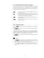
6.5 Control elements on the front panel
The front panel has four keys to control your PRE G2 (see section
'Overview front panel' on page 7). With these keys you can control all
functions as well as all setup options to adjust the unit to your preferences
(see section 'Setup Menu' on page 19).
mute
Use this key to mute or de-mute the PRE G2 (see section
'Muting' on page 18).
set
Push key shortly to navigate through the setup menu. Keep
key pushed for longer than two seconds to exit the setup
menu (see section 'Setup Menu' on page 19).
input
Push key to enter input selection (see section 'Input selection' on page 17).
power
Use key to switch on/off the unit (see section 'Switching on
and off' on page 13).
6.6
Volume control
Use the volume knob on the front panel of the PRE G2 to set the desired
volume level.
Turn volume knob clockwise to increase volume, turn counter clockwise
to decrease volume.
The volume control of the PRE G2 runs in a range from –80 dB to
+10 dB in real 1 dB steps relatively to the level of the input signal. Differences in input levels can be adjusted for each input channel of the
PRE G2 separately (see section 'Offset Adjust' on page 22).
The volume knob is a magnetically buffered incremental impulse encoder
without end stop.
Note
·
The volume knob is also used to select an option from the setup menu
items (see section 'Offset Adjust' on page 22) as well as to select the
input channel (see section 'Input selection' on page 17).
·
To control the volume with the Audionet Metal Remote Control RC 1
use keys VOL+ and VOL (see section 'Key assignment PRE G2' on
page 31).
15
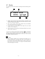
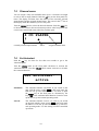
6.7
Display
The display provides in the normal operating mode the following information:
1
2
5 INPUT FIVE
LEVEL –46+0dB
3
4
1
number of the currently selected input channel, corresponds to the
number printed above the input jack on the back panel (see section
'Overview back panel' on page 8)
2
name of the currently selected input channel, fully user-definable
(see section 'Channel name' on page 24)
3
current volume level in dB relative to the input level (see section
'Volume control' on page 15).
4
offset for input level of currently selected input channel (see section
'Offset Adjust' on page 22).
As soon as you enter the setup menu by pushing the set key, the display
changes to show information related to the selected menu item. For further display details refer to the description of each menu item in section
'Setup Menu' starting from page 19.
Note
·
After 10 minutes without any user interaction the 'display saver' is
invoked automatically. The display then shows only the number of
the currently selected input channel and the current volume level.
Please refer to section 'Set Dim Level' on page 20 for further information on the 'display saver' mode.
16
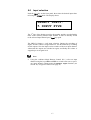
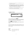
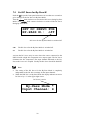
6.8
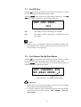
Input selection
Push the input key on the front panel, then select the desired input channel using the volume knob. The display shows:
SELECT INPUT:
5 INPUT FIVE
The 2nd line of the display provides the number and the (user-definable)
name of the currently selected input channel. In order to actually switch
to the selected input channel press input key again.
The PRE G2 features a 'soft' input selection. During the switching of
inputs, first the volume is stepped down to –80 dB, followed by switching
off the outputs. Now the input section switches to the new input channel.
Afterwards the outputs are switched on again, and finally the volume is
stepped up to its original level.
Note
·
Using the Audionet Metal Remote Control RC 1, select an input
channel using the keys CH+ and CH- to switch to the next or previous input channel without using the Select Input function (see
section 'Key assignment PRE G2' on page 31).
17
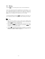
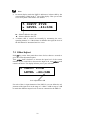
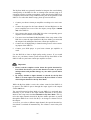
6.9
Muting
Push the mute key on the front panel to mute or un-mute the PRE G2.
Just as well as the input selection, the PRE G2 uses 'soft' muting, i.e. volume is stepped down gently to –80 dB, then the outputs are switched off.
The 2nd line of the display informs the user of a muted unit with the text
MUTE. The text is displayed even if the dim level is set to Off.
To de-mute the PRE G2 press the mute key again. Here as well, the volume is stepped up gently to its original level after switching on the outputs.
Note
·
While the unit is muted, you may of course select a different input
channel as described above. But the PRE G2 will stay muted until you
push the mute key again to de-mute the unit.
·
If you turn the volume knob, while the unit is muted, the new volume
level will be set and the unit de-muted, if you turn the volume knob
clockwise, i.e. you turn up the volume.
·
Use key
on the Audionet Metal Remote Control RC 1 to control the
muting of your PRE G2 from the comfort of your listening chair (see
section 'Key assignment PRE G2' on page 31).
18
7
Setup Menu
To adjust the PRE G2 to your preferences, please use the setup menu.
Push the set key shortly on the front panel to get to the first item of the
setup menu. Navigate to the next menu item by pushing the set key
shortly. Below you will find a list of all menu items of the setup menu.
After last menu item pushing the set key leaves the setup menu automatically.
Of course, you may leave the setup menu from each menu item by pushing and holding the set key for longer than two seconds. The PRE G2
will return to normal operation mode.
The order of items in the setup menu is:
ê*1
SET DIM LEVEL
ê
BALANCE ADJ.
ê
OFFSET ADJUST
ê
SET DC SERVO
ê
channel name
ê
SET AUTOSTART
ê
SET OFF-TEXT
ê
SET CHANNEL FOR BY-PASS MODE
ê
SET DC SERVO FOR BY-PASS M.
Change any setting of a menu item using the volume knob on the front
panel.
*1
ê = push set key shortly (less than two seconds)
19
Note
·
If you make no adjustments for longer than 12 seconds the PRE G2
will automatically leave the setup menu and return to normal operations mode.
·
While you are in the setup menu the display brightness is set to 100%
for better readability. After leaving the setup menu the display
brightness is automatically reset to is user selected level.
·
If you power down the PRE G2 to stand-by mode all settings are
stored automatically in the non-volatile memory of the unit. Even after disconnecting from mains the PRE G2 will still remember your
settings.
In the following all options of the setup menu are explained in detail.
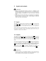
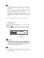
7.1 Set Dim Level
To adjust the brightness of the display on the front of the PRE G2 press
the set key once for less than two seconds.
Now use the volume knob to select the desired brightness. Turn clockwise to increase or turn counter clockwise to decrease the brightness.
SET DIM LEVEL:
██████______ 50%
current brightness setting
Important
·
Long-term usage of the display set to maximum brightness (setting 100%) may cause extended signs of wear resulting in a decay
of contrast or brightness of individual dots in the display. Do not
use the display with a brightness set higher than the factory default of 50% over a longer period of time!
Note
·
Is the brightness set to Off the display is only on during setup or
volume adjustments. It switches off automatically several seconds after the last user entry.
20
·
The PRE G2 activates the 'display saver' automatically after 10 minutes without any user entry.
·
During active 'display saver', the display shows only the number of
the selected input channel and current volume level in the form of
In 4 -47dB. The display brightness is always reduced to 25%, and
the location of the information text will change randomly every 12
seconds to prevent any 'burn-in' effect of the display.
·
The 'display saver' is de-activated and the display returns to its normal mode as soon as any user entry is detected.
·
The user cannot switch off the automatic 'display saver' function!
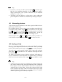
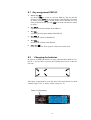
7.2 Balance Adjust
Push set key twice for less than two seconds. The display reads now:
BALANCE ADJ.: +0
-current balance setting in dB
Adjust now the balance by using the volume knob.
Turn clockwise to shift the balance to the right. The 1st line of the display
shows the volume difference in dB between left and right channel. A
positive value means that the balance is shifted to the right.
Turn the volume knob counter clockwise to shift the balance to the left.
The value in the display is now negative.
The PRE G2 allows the user to shift the balance up to 9 dB to the left or
the right.
The 2nd line of the display visualises a balance shift with one or more
symbols. The orientation of the symbol represents the direction of the
balance shift, the number of symbols equals the amount of 1 dB steps the
balance was shifted.
Example:
►►►
balance shifted to the right by 3 dB
◄◄◄◄◄
balance shifted to the left by 5 dB
––
no balance shift
21
Note
·
In normal display mode the PRE G2 indicates a balance shift by the
corresponding symbol in the 2nd line of the display. Thus you are able
to see at any time if the balance was shifted:
5 INPUT FIVE
► LEVEL –46+0dB
► = balance shifted to the right
◄ = balance shifted to the left
·
A balance shift is carried out internally by attenuating the corresponding channel, i.e. if the balance is shifted to the right, the level of
the left channel is attenuated and vice versa.
7.3 Offset Adjust
Push set key on the front panel three times for less than two seconds to
get to the offset adjustment option.
Turn volume knob clockwise to increase the input level of the current
channel. If you would like to decrease the input level, turn volume knob
counter clockwise. The display informs you of your selection:
5 INPUT FIVE
LEVEL –46+3dB
level adjustment in dB
For each of the six input channels of the PRE G2 you can define the adjustment of the input level in the range of –9 dB to +9 dB in steps of 1 dB
to match the different output levels of sources connected to the PRE G2.
22
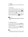
7.4
Set DC Servo
Push the set key four times for less than 2 seconds to adjust the DC Servo
option.
Turn volume knob on the front panel clockwise to activate the DC Servo
for the currently selected input channel. Turn volume knob counter
clockwise to disable the DC Servo.
SET DC SERVO:
In 3 : disabled
status DC Servo
current selected input channel
disabled
The DC Servo is disabled for the currently selected input
channel.
active
The DC Servo is active for the currently selected input
channel.
Activate the DC Servo if the source connected to the PRE G2 holds a
high DC component in its output signal. The DC Servo eliminates the DC
component. The currently selected input channel is now AC-coupled.
Usually the DC Servo may be disabled.
Note
·
In normal operating mode the display indicates an active DC Servo
for the currently selected input channel by a symbol right beside the
channel name in the 1st display line. Thus you can see at any time if
the DC Servo is active:
DC Servo is active
5 INPUT FIVE
*
LEVEL –46+0dB
23
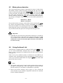
7.5
Channel name
You can assign a fully user-definable name up to 12 characters in length
to each of the six input channels. Push the set key on the front panel five
times. The display will then show the number of the currently selected
input channel and the assigned channel name. The cursor in the 2nd line of
the display marks the character you now may alter.
Turn the volume knob to select the desired character. Push the mute key
to advance the cursor to the next character position. After last position the
cursor wraps around and starts at the first position again.
4 CD PLAYER
▲
currently selected input channel
7.6
cursor
assigned channel name
Set Autostart
Push the set key six times for less than two seconds to get to the
Autostart option.
Turn the volume knob on the front panel clockwise to activate the
Autostart function. Turn the volume knob counter clockwise to disable
the Autostart function.
SET AUTOSTART:
active
disabled
The Autostart function is disabled. If you switch on the
unit with the mains switch 14 on the back panel the
PRE G2 will go into stand-by mode. You have to push
the power key on the front panel or, alternatively, the
keys PRE of the Audionet Metal Remote Control to start
up the unit to go into normal operating mode.
active
The Autostart function is active. As soon as you switch
on the unit with the mains switch 14 on the back panel
the PRE G2 will start up and automatically go into normal operating mode. Use this setting for timer controlled
operations.
24
7.7
Set Off-Text
Push the set key on the front panel seven times for less than two seconds
to select the display option during stand-by mode.
Turn the volume knob clockwise to select display option 'dot'. Turn volume knob counter clockwise to select display option 'off'.
SET OFF-TEXT:
dot
off
The stand-by mode is indicated by the text off.
dot
The stand-by mode is indicated by a small dot (pixel) in
the display.
Note
·
Approx. every 12 seconds the stand-by mode indicator changes position randomly in the display to prevent any 'burn in' effect (see section 'Set Dim Level' on page 20).
7.8
Set Channel for By-Pass Mode
Push the set key on the front panel eight times for less than two seconds
to enter the option for selecting the input channel in By-Pass Mode.
Use the volume knob on the front panel to select the input channel you
would like to use for the By-Pass Mode.
SET CHANNEL FOR
BY-PASS MODE: 3
dot
input channel no. 3 is used in By-Pass Mode
Important
·
Before you can use the By-Pass Mode you have to select the input
channel that is used for the By-Pass Mode.
·
For safety reasons the factory default settings have no input channel
selected for By-Pass Mode (display: SET CHANNEL FOR BYPASS MODE: - -).
25
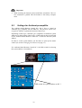
The By-Pass Mode was primarily intended to integrate the overwhelming
sound quality of the PRE G2 into an existing home cinema setup or to
expand an existing excellent stereophonic system based on the PRE G2 to
a complete home cinema setup without missing out on the qualities of the
PRE G2. To realise this kind of setup, please proceed as follows:
1. Connect your home cinema pre amplifier according to its user's manual.
2. Connect the output for the front channels Left and Right not to the
power amplifier but to one of the free inputs (except input 6 'PHONO
IN') of the PRE G2.
3. Now connect the outputs of the PRE G2 to the corresponding power
amplifier for the channels Left and Right.
4. Use menu item 'Set Channel for By-Pass Mode' of the setup menu of the
PRE G2 to select the input channel for By-Pass Mode you connected
the outputs Left and Right of the home cinema pre amplifier to.
5. Connect now all high quality 2-channel analog sources to the remaining inputs of the PRE G2.
6. Connect your DVD player to your home cinema pre amplifier as
usual.
Use the PRE G2 to listen to high quality analog sources. If you would
like to use your home cinema system activate the By-Pass Mode of the
PRE G2 and use your home cinema pre amplifier as usual.
Important
·
Please read the complete section about the special function ByPass Mode first before you use this function in order to prevent
maloperations and possible damage to your audio system and/or
hearing.
·
By factory default no input channel is selected for the By-Pass
Mode. Use menu option 'Set channel for By-Pass Mode' to select
desired input channel for the By-Pass Mode.
While the By-Pass Mode is active the volume control of the PRE G2 is
by-passed. The PRE G2 passes through the input signal to the outputs
with its full level.
The special function By-Pass Mode of your PRE G2 is activated automatically if you switch to the input channel dedicated to the By-Pass
Mode in the setup menu item Set Channel for By-Pass Mode. The signal at the input channel selected for By-Pass Mode operations is passed
through the PRE G2 at a level of 0 dB (i.e. no change in volume level) to
the outputs.
As soon as you select a different input channel, the special function ByPass Mode is switched off automatically. The volume is reset to the prior
level.
26
Important
·
Please check the correct connection and setup before you use the
By-Pass Mode for the first time. The input signal will be passed
through to the outputs at full level!
As soon as the By-Pass Mode is activated, the PRE G2 will ignore all
control commands coming from the keys on the front panel or remote
control (exceptions see below)!
Important
There are only two possibilities to disable the By-Pass Mode:
1.
Select a different input channel. The PRE G2 switches back to the
newly selected input channel selected before resetting the volume to
its prior level.
2.
Push the power key on the front panel or the PRE key on the Audionet Metal Remote Control RC 1 or RC 2. The PRE G2 switches off
to stand-by mode.
Note
·
If you leave the By-Pass Mode by pushing the power key on the
front panel or PRE key on the Audionet Metal Remote Control RC 1
or RC 2, this mode will be saved, i.e. if you switch on the PRE G2,
the unit will switch to the last saved input channel selection and thus
into By-Pass Mode.
27
7.9
Set DC Servo for By-Pass M.
Push the set keyon the front panel nine times for less than two seconds to
get to settings for the DC Servo in By-Pass Mode.
Turn the volume knob clockwise to activate the DC Servo during By-Pass
Mode. Turn volume knob counter clockwise to switch off the DC Servo
during By-Pass Mode'.
SET DC SERVO FOR
BY-PASS M.: off
dot
DC Servo for the By-Pass Mode is switched off
off
The DC Servo for the By-Pass Mode is switched off.
on
The DC Servo for the By-Pass Mode is switched on.
Activate the DC Servo only in cases where the source connected to the
PRE G2 holds a high DC component in its output signal. The DC Servo
eliminates the DC component. The input channel dedicated to the ByPass mode is now AC-coupled. Usually the DC Servo should be disabled.
Note
·
The setting of the DC Servo for the By-Pass Mode is completely
independent to the DC Servo settings for the input channels.
·
While the PRE G2 is in By-Pass Mode the display indicates an active
DC Servo by a '*' in the upper right corner:
DC Servo is active
By-Pass Mode *
Input Channel: 4
28
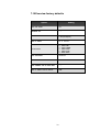
7.10 Overview factory defaults
Option
Setting
SET DIM LEVEL
50%
BALANCE ADJ.
- -
OFFSET ADJUST
0 dB (for all inputs)
SET DC SERVO
In 1-5: disabled
In 6: active
Channel name
1:
2:
3:
4:
5:
6:
SET AUTOSTART
disabled
SET OFF-TEXT
dot
SET CHANNEL FOR BY-PASS MODE
- -
SET DC SERVO FOR BY-PASS M.
off
29
BALANCED
INPUT TWO
INPUT THREE
INPUT FOUR
INPUT FIVE
TAPE INPUT
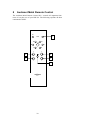
8
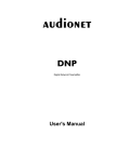
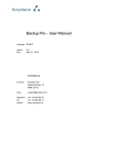
Audionet Metal Remote Control
The Audionet Metal Remote Control RC 1 controls all important functions of everyday use of your PRE G2. The following explains all these
commands in detail..
PRE
ART
1
POWER
9
:
4/;
ä
<
7
8
+
+
CH
VOL
2
4
3
5
–
–
6
audionet
RC 1
30
8.1 Key assignment PRE G2
1
Power key PRE
use the key PRE to switch on / off your PRE G2. This key has the
function as key power on the front panel. If the PRE G2 is in standby mode, press key PRE to switch on this unit. If the PRE G2 is already switched on, then pressing PRE powers the unit down to standby mode.
2
Key CH +
selects the next input channel of the PRE G2.
3
Key CH selects the previous input channel of the PRE G2.
4
Key VOL +
increases the volume of the PRE G2.
5
Key VOL decreases the volume of the PRE G2.
6
Mute key
mutes the PRE G2. Press again to resume last volume level.
8.2
Changing the batteries
In order to exchange the batteries of your Audionet Metal Remote Control RC 1, first you have to remove the 6 Phillips head screws on the bottom side.
The battery compartment is to the left side of the circuit board. You need
2 batteries type 'AAA' or 'Micro' with a voltage of 1.5V.
Battery compartment
31
Important
·
While inserting the batteries please mind their orientation. The correct orientation is printed onto the bottom of the battery compartment.
8.3
Settings for Audionet preamplifier
The Audionet Metal Remote Control RC 1 has 6 keys to control an
Audionet (pre-) amplifier like the PRE G2. The previous section 'Key
assignment PRE G2' explains the function of these keys.
Depending on their type, Audionet (pre-) amplifiers use different system
addresses for their remote control code. A DIP switch on the circuit board
of the Audionet Metal Remote Control RC 1 selects the desired system
address.
In order to set the system address you first have to open up the remote
control (see section 'Changing the batteries' on page 31).
For Audionet Metal Remote Control RC 1 the DIP switch for selecting
the system address is located here:
DIP switch for system address on RC 1
32
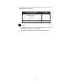
Put the DIP switch labelled 'SYS ADDRESS' in position '19' or '16' according to the following table:
Audionet preamplifier
Address
PRE G2, PRE 1 G3,
SAM G2,
19
DNA, DNP, DNA 1
MAP 1
16
Note
·
If not ordered explicitly, the Audionet Metal Remote Control is preconfigured to setting '19' of the DIP switch.
·
Older models of Audionet preamplifiers use system address 16.
33
9
9.1
Technical information
Design
The PRE G2 has complete double mono design for absolute channel
separation. To optimize the high frequency properties the circuitry was
consequently miniaturized and SMD technology implemented. Signal
path ways are limited to their minimum, and chassis and circuit design
magnetically and capacitively optimized. The System is controlled and
monitored by a powerful microprocessor. The control unit and the analog
section are galvanically separated by opto-couplers.
9.2
Power supply
Power is provided by two encapsulated 100 VA toroid core transformers.
Fast buffer capacitors, especially designed for Audionet, with 82.000 mF
for each channel and extremely fast, discrete regulators stabilize the supply voltages. Additionally, voltages are smoothed locally by 12 regulators
for each channel. Thus, the power supply is quasi de-coupled from mains
accumulator-like. Also, the digital section has its separate power supply.
9.3
Circuitry
All operational amplifiers (OP) in the signal path are discrete and optimized for their special purpose. Each OP is supplied with power by to
fast and discrete regulators. All 10 discrete OP modules work in low distortion Class A mode and have a gain-bandwidth product of 1.5 GHz.
The input OPs have a nearly infinite input impedance and constant capacity. Thus, they do not load the signal source. Gold plated precision relays
switch both signal and ground of the inputs.
The output OPs work in high bias current Class A mode rendering them
immune against reflux of the power amplifiers.
Volume and balance is controlled, free of electro-mechanical components, by an electronically switched and in real-time linearized precision
resistor network with true 1 dB resolution.
34
9.4
Handling
A microprocessor controls and monitors all functions. A two line, 16digit display informs the user about all operating modes and makes it
easy to adjust the PRE G2 to the user's preferences. The unit also features
user-definable channel names and input level adjustment for each channel. Two 'Audionet Link' outputs facilitate easy daisy-chaining of Audionet devices for remote switching on/off via 'Audionet Link'. Each input
channel features a user selectable DC Servo to eliminate DC components
on source signals.
9.5
Update PRE to PRE G2
Note
·
An Audionet PRE updated to PRE G2 does not feature a DC Servo.
The corresponding menu item in the setup menu is omitted for these
units. Quality of performance and appearance is the equal to the
original PRE G2.
35
10 Security advice
Important
·
Avoid packaging material, especially plastic bags, coming into children's hands!
·
Store and operate the unit in a dry room at a reasonable room temperature only!
·
Avoid moisture, any liquids, dirt or small objects getting into the
unit!
·
Set up the unit in a sufficiently ventilated environment!
·
Do not cover the unit!
·
Do not open the unit. Unauthorised opening will void warranty!
·
Do not short-circuit the outputs!
·
During connecting or removing the PRE G2 to/from sources and/or
power amplifiers all units have to be switched off to prevent damage
of the PRE G2 or any of the other connected units.
·
Use dry cloth for cleaning!
We would like to wish you many exciting listening experiences with your
new Audionet product.
If you still have any questions, do not hesitate to ask your competent
Audionet dealer or contact us directly.
36
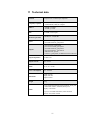
11 Technical data
Function
microprocessor controlled pre-amplifier
Frequency response
0 – 2,000,000 Hz (-3 dB), DC coupled
2 – 2,000,000 Hz (-3 dB), AC coupled
THD+N
<-102 dB @ 20 kHz
<-114 dB @ 1 kHz
SNR
> 110 dB, 2 VRMS input
Channel separation
>140 dB, 20 – 20,000 Hz
Inputs
5 pair Cinch line, gold plated
1 pair XLR balanced, gold plated
Outputs
1 pair Cinch line, gold plated
1 pair Cinch inverted, gold plated
2 pair XLR balanced, gold plated
1 pair Cinch Monitor, gold plated
2 Audionet Link, optical
1 connector, gold plated, for additional earth connection
Output impedance
22 Ohms real
Output current
max. 60 mA
Mains
230 V, 50…60 Hz
Power consumption
max. 50 Watts
Dimensions
Width 430 mm
Height 140 mm
Depth 420 mm
Weight
20 kg
Front: brushed aluminium, black anodised, white print
or aluminium 'nature', anodised, black print
Finish
Display: red or blue
Top cover: brushed aluminium, black anodised
Chassis: steel, black coated
37
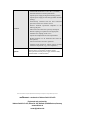
Features
Options
-
Audionet Metal Remote Control RC 1 (included)
-
automatic detection of main polarization
-
separate power supply for digital and analog sections
-
separate power supply for left and right audio channels
(analog)
-
electronically switched and real time linearised
precision resistors for volume control
-
discrete Audionet operational amplifiers in the
audio signal path
-
audio and control functions optically decoupled
-
full DC coupling, no capacitors in the signal path
-
selectable AC coupling via DC servo
-
separate level adjustment for each input channel
-
By-Pass function (e.g. for integration into home cinema systems)
-
Auto start function for timer operations
-
Audionet Link outputs for remote control of other
Audionet components (e.g. power amplifiers)
recommended for phono applications:
external phono pre-amplifier Audionet PAM
(with optional external power supply Audionet EPS,
Audionet EPX or Audionet EPC)
Errors and omissions excepted. Specifications and design are subject to changes without prior notice.
audionet is a trademark of Idektron GmbH & Co KG
Engineered and produced by:
Idektron GmbH & Co. KG, Herner Str. 299, Gebäude 6, 44809 Bochum, Germany
www.audionet.de
[email protected]
38