1
Stereo Pre-Amplifier
User's Manual
1
2
Contents
1
Preface ...................................................................... 5
1.1
Included........................................................................................6
1.2
Transport .....................................................................................6
2
Overview front panel................................................ 7
3
Overview back panel................................................ 8
4
Installation and power supply ................................. 9
4.1
Placement .....................................................................................9
4.2
Mains connection.........................................................................9
4.3
Orientation of mains plug.........................................................10
4.4
Additional earth connection .....................................................10
5
Inputs and outputs ................................................. 11
5.1
Inputs..........................................................................................11
5.2
Outputs.......................................................................................11
5.3
Recording devices......................................................................12
5.4
Monitor ......................................................................................12
5.5
Phono..........................................................................................12
5.6
Audionet Link............................................................................13
5.7
External power supply EPS .....................................................13
5.8
Trigger output ...........................................................................14
6
Usage....................................................................... 15
6.1
Powering up ...............................................................................15
6.2
Switching on and off .................................................................15
6.3
Mains phase detection...............................................................16
6.4
Using Audionet Link.................................................................16
6.5
Control elements on the front panel ........................................17
6.6
Volume control ..........................................................................17
6.7
Display........................................................................................18
6.8
Input selection ...........................................................................19
6.9
Muting ........................................................................................19
7
Setup menu............................................................. 21
3
7.1
Set Input .....................................................................................22
7.2
Set Monitor ................................................................................23
7.3
Set Headphones .........................................................................24
7.4
Set Dim Level.............................................................................25
7.5
Balance Adjust...........................................................................26
7.6
Offset Adjust..............................................................................28
7.7
Set DC Servo..............................................................................28
7.8
Channel name ............................................................................29
7.9
Set Out 2 (Sub) ..........................................................................31
7.10
Set Autostart ..............................................................................32
7.11
Set Channel for By-Pass Mode........................................................32
7.12
Overview factory defaults.........................................................33
8
Audionet System Remote Control.........................34
8.1
Key assignment PRE1 G3.........................................................36
8.2
Screen 1 ......................................................................................37
8.3
Screen 2 ......................................................................................38
8.4
Screen 3 ......................................................................................39
9
Special function By-Pass Mode.............................40
10
Technical information.............................................42
10.1
Design .........................................................................................42
10.2
Power supply..............................................................................42
10.3
Circuitry.....................................................................................42
10.4
Handling.....................................................................................42
11
Security advice........................................................43
12
Technical data .........................................................44
4
1
Preface
The Audionet Team congratulates you on your purchase of this unit.
But before you start listening to your new Audionet PRE1 G3, please
read this manual carefully so you are able to use and enjoy all functions
of this unit without drawback on music quality.
5
1.1 Included
Included you will find the following items:
·
the stereo pre-amplifier PRE1 G3
·
the user's manual (that you are currently reading)
·
one standard mains cord
·
one green-yellow cord for an additional earth connection
1.2 Transport
Important
·
Please transport the PRE1 G3 only in the included package.
·
Always use the plastic bag to prevent scratches on the casing.
·
Please allow the PRE1 G3 to adapt to the climatic conditions in your
listening room before you switch on the unit for the first time after
transport.
6
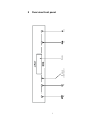
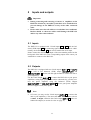
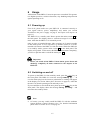
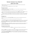
power
key
power
set
key
set
IR remote
control receiver
Stereo Preamplifier
PRE 1 G3
Display
down
down
key
up
up
key
2
Overview front panel
7
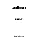
8
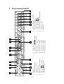
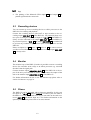
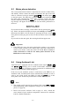
12 Cinch input no. 5, left/right
13 Cinch input no. 4, left/right
14 Cinch input no. 3, left/right
Headphones output
Balanced (XLR) output, left/right
Cinch output OUT 1, left/right
Cinch output OUT 2, left/right
or Subwoofer (2x Mono)
4
5
6
7
15 Cinch input no. 2, left/right
11 Cinch input no. 6, left/right
10 Earth connector for turn table (phono)
Trigger output (12 Volt)
13
12
11
5-pin connector for external power supply EPS
22 Mains input
21 Marking mains phase
20
19 Audionet Link output OUT 2
18 Audionet Link output OUT 1
17 Monitor input, left/right
14
Balanced (XLR) input no. 1, left/right
15
Recording output REC OUT, left/right
16
9
9
16
17
8
Monitor output, left/right
7
8
6
3
18
5
Additional earth connector
19
4
2
20
3
Mains switch
21
2
1
22
1
10
3
Overview back panel
4
Installation and power supply
Important
·
During connecting and removing of sources or amplifiers to the
PRE1 G3 all units of your audio system have to be switched off to
prevent damage of the PRE1 G3 or any of the other connected units.
·
Please make sure that all cables are in absolute best conditions!
Broken shields or short-cut cables could damage the PRE1 G3
and/or any other connected unit.
4.1 Placement
Important
·
It is recommended to place the PRE1 G3 into a high quality rack or
onto a stable table.
·
Do not expose the unit to direct sunlight.
·
Do not cover the ventilation slots.
·
Do not place the PRE1 G3 in close range to heat sources like radiators.
·
Do not place the PRE1 on top of other units, especially not on top of
power amplifiers, pre amplifiers or similar that produce heat. Both
units could suffer damage from thermal overload.
·
Do not use the unit in places where it is exposed to vibrations.
·
Do not place the unit close to loudspeakers or into the corner of a
room where it is exposed to high levels of sonic energy, which might
reduce the sound quality of the unit.
4.2 Mains connection
The mains input 21 * is on the back panel of the PRE1 G3. To connect the
unit to mains use the included mains cord. If you prefer to use a different
power cord make sure that it meets the specifications for your home country.
Important
·
*
The electrical specifications of your home country must meet the
electrical specifications printed onto the back panel.
see numbers in section 'Overview back panel' on page 8.
9
·
The PRE1 G3 is a Class I unit and must be earthed. Please ensure a
stable earth connection. Phase ('hot' pin) is marked on the back panel
('phase') 21 .
·
If you connect the mains cord please make sure that mains switch 1
at the back panel is switched off.
·
Never pull the mains plug while the PRE1 G3 is switched on! Before
you pull the mains cord off its socket 22 at the back panel, power down
the unit to stand-by mode and switch off the unit using mains switch 1 .
Only in cases of extended absence – like vacations – or if massive trouble
on the mains power is to be expected you should switch off the PRE1 G3
from the mains using mains switch 1 . To disconnect the unit completely
from mains pull the mains plug.
Tip
·
The use of high quality mains cords could improve sound quality.
Ask your local dealer for more information.
4.3 Orientation of mains plug
The correct polarization of mains is important for reasons of audio clarity
and stability. Please connect the mains cord so that the hot pin of the wall
outlet is connected to the pin of the mains input 22 marked 'phase' 21 .
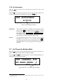
Your Audionet PRE1 G3 is able to detect a wrong polarization of the
mains plug during start-up. If the message
Attention: Mains
Phase incorrect!
appears in the display, switch off the unit and flip the mains plug in the
wall outlet (see section 'Mains phase detection' on page 16).
4.4 Additional earth connection
Included with the PRE1 G3 you will find a green-yellow cord for the
additional earth connection. Attach this cord to the earth connector 2 on
the back panel of the PRE1 G3 and put the plug into the mains socket
right beside the mains cord of your PRE1 G3. This ensures an additional
and stable earth connection resulting in a better sound.
Note
·
We strongly recommend using the additional earth connection!
·
Also, a stable earth connection is necessary for the PRE1 G3 detecting the polarization of mains phase correctly.
10
5
Inputs and outputs
Important
·
During connecting and removing of sources or amplifiers to the
PRE1 G3 all units of your audio system have to be switched off to
prevent damage of the PRE1 G3 or any of the other connected
units.
·
Please make sure that all cables are in absolute best conditions!
Broken shields or short-cut cables could damage the PRE1 G3
and/or any other connected unit.
5.1 Inputs
The PRE1 G3 is equipped with 5 Cinch inputs 11 to 15 and one balanced (XLR) input 16 for connecting signal sources at line level. Additionally, the monitor input 17 can used as another line level input.
Please connect the left and right input of the same number printed on the
back panel of the PRE1 G3 to the corresponding output of the source you
would like to connect to the PRE1 G3.
5.2 Outputs
The PRE1 G3 is equipped with two Cinch outputs OUT 1 6 and OUT 2
7 as well as one balanced (XLR) output XLR OUT LEFT and
XLR OUT RIGHT 5 for the left and right channel to connect the unit to
your amplifier(s).
Use the Cinch output OUT 1 6 to connect the PRE1 G3 to your power
amplifier(s) using high quality Cinch cables. Alternatively, you may connect the power amplifier using the balanced (XLR) outputs
XLR OUT LEFT and XLR OUT RIGHT 5 in case your power amplifier
does not support Cinch (line) inputs.
Note
·
Of course you may use the Cinch output OUT 2 7 to connect the
unit to your amplifier(s). The menu item SET SUB OUT has to be set
to Left & Right, otherwise the Cinch output OUT 2 7 works as a
Subwoofer output (see section 'Set Out' on page 31).
11
Tip
·
The pinning of the balanced (XLR) input 16 and output 5 is
printed right beside the connectors.
5.3
Recording devices
You can connect up to two recording devices or effect processors to the
PRE1 G3 for recording and playback.
Connect the recording devices (like DAT or tape recorder) to the recording output REC OUT 9 of the PRE1 G3. For playback please connect your recording devices only to input no. 5 IN 5 12 of the PRE1 G3.
if they are also connected to the output REC OUT 9 of your PRE1 G3.
If you select input no. 5 IN 5 12 the output REC OUT 9 is switched off
to prevent any feedback loops between your recording device and the
PRE1 G3.
Please use inputs no. 1 16 to no. 4 13 and no. 6 11 to connect sources
you like to record from. With these inputs the recording output REC OUT
9 is always active
5.4
Monitor
The monitor loop of the PRE1 G3 makes it possible to insert a recording
device (for read after write verify) or an effects processor (e.g. surround
decoders) into the signal path.
Connect monitor output MONITOR OUT 8 of the PRE1 G3 to the input of the unit you would like to insert. Also, connect the output of the
unit to the monitor input MONITOR IN 17 of the PRE1 G3.
For further information on how to use the monitor loop please refer to
section 'Set Monitor' on page 23.
5.5
Phono
The PRE1 G3 can be upgraded with a phono pre amplifier. In this case
use input no. 6 IN 6 11 marked PHONO to connect your turn table to
the PRE1 G3. Connect the earth wire of your turn table to the earth connector GND 2 right beside input no. 6. For further information on the
optional phono module please refer to its user's manual.
12
Important
·
If the PRE1 G3 is upgraded with the optional phono module, input
no. 6 IN 6 11 must only be used to connect a turn table.
5.6 Audionet Link
For your convenience, the PRE1 G3 can switch on/off all other Audionet
units (e.g. power amplifiers) connected via 'Audionet Link' by a simple
touch on the remote control or the power key on the front panel.
You only need a simple optical 'Toslink' cable. Connect the 'Audionet
Link' output OUT 1 18 or OUT 2 19 of your PRE1 G3 to the 'Audionet Link' input of unit to be controlled.
The PRE1 G3 is equipped with two 'Audionet Link' outputs OUT 1 18
and OUT 2 19 . 'Audionet Link' output 1 OUT 1 18 is always on
while the PRE1 G3 is switched on. However, 'Audionet Link' output
OUT 2 19 is controlled depending on the settings for the headphones
output. Please refer to section 'Set Headphones' on page 24.
Therefore, use 'Audionet Link' output OUT 2 19 in order to connect
power amplifiers to the PRE1 G3 via 'Audionet Link'. Connect units you
would like to control independently from the headphones settings (e.g.
tuner, CD player etc) to 'Audionet Link' output OUT 1 18 .
Tip
·
Audionet source units and power amplifiers are usually equipped not
only with an 'Audionet Link' input, but additionally with an 'Audionet
Link' output to connect further Audionet devices to be controlled via
'Audionet Link' in a daisy chain. Connect this 'Audionet Link' output
to the 'Audionet Link' input of the next Audionet unit using a simple
optical 'Toslink' cable allowing you to switch on/off your complete
Audionet system by your Audionet pre amplifier.
5.7
External power supply EPS
In order to use the optional external precision power supply Audionet
EPS (External Power Supply) with you PRE1 G3 please proceed as follows:
1.
Make sure both PRE1 G3 and EPS are switched off and disconnected from mains.
2.
Connect the EPS with the included cable to input jack EPS 20
on the back panel of the PRE1 G3. The shape of the plug prevents any wrong polarity. The small 'nose' inside the plug has to
13
face upwards. Now screw the ring of the plug onto the EPS input
jack 20 .
3.
Connect both (!!) units (PRE1 G3 and EPS) to mains.
4.
First, switch on the EPS on its back panel. Then switch on the
PRE1 G3 with the mains switch 1 .
5.
Use the power key on the front panel or the keys Power On or
Power Toggle *) of the Audionet System Remote Control Harmony One to switch on the PRE1 G3. The PRE1 G3 is now ready
to use and gets its power from the external power supply EPS.
6.
To switch off the PRE1 G3 into stand-by mode, use the power
key on the front panel or keys Power Off or Power Toggle *)
of the Audionet System Remote Control Harmony One.
Important
·
Never switch on or off the EPS on its back panel while the
PRE1 G3 is operating.
·
For further information referring to the external power supply EPS
please consult its user's manual.
Tip
·
Use a high quality cable (for example the Audionet APC) to connect
the EPS to mains. The sound will improve.
5.8
Trigger output
Use trigger output TRIGGER 3 to control (e.g. switch on/off) nonAudionet devices. If you switch on the PRE1 G3 from stand-by mode, the
trigger ouput 3 provides a signal of 12 Volts DC. If you power down the
unit to stand-by mode, the signal of the trigger output 3 will be 0 Volts.
Tip
·
Use a 3.5 mm telephone mono plug to connect a device to the trigger
output 3 of your PRE1 G3. The pinning is as follows:
Ground
*)
12 Volt DC
or switched on/off by Activities on the Audionet System Remote Control; see separate user's
manual Harmony One
14
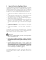
6
Usage
All functions of the PRE1 G3 are microprocessor controlled. This guarantees highest precision, exclusive functions, easy handling and protection
against operating errors.
6.1 Powering up
First of all, please make sure your PRE1 G3 is connected correctly to
your signal sources, power amplifier(s) and mains (see section
'Installation and power supply' on page 9 and 'Inputs and outputs' on
page 11).
The PRE1 G3 is a stand-by unit. Please operate the mains switch 1 on
the back panel. The display shows a welcome message for a brief moment. After that the PRE1 G3 is in stand-by mode.
Only in cases of extended absence (like vacations) or if massive trouble
on the mains power is to be expected (e.g. thunder storms) it is recommended to disconnect the PRE1 G3 from the mains. While the PRE1 G3
is in stand-by mode, operate mains switch 1 on the back panel. The
display will go dark. To disconnect the PRE1 G3 from mains completely,
you have to pull the mains cord off the mains jack 22 .
Important
·
Before you switch off the PRE1 G3 from mains, power down and
discharge completely all units connected to the outputs of the
PRE1 G3.
6.2 Switching on and off
To power up the PRE1 G3 from stand-by mode, press the power key on
the front panel. The PRE1 G3 issues the message Waking up.... In
case the mains plug has the incorrect polarization a warning will appear
in the display (see section 'Mains phase detection' on page 16). After that
the unit is in normal operating mode and ready to use.
If you would like to switch off the unit, please press the power key on the
front panel. The display shows the message Going to sleep.. and
unit enters the stand-by mode.
Note
·
Of course, you may switch on/off the PRE1 G3 with the Audionet
System Remote Control Harmony One. For detailed information
please refer to section 'Screen 3' on page 39.
15
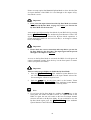
6.3
Mains phase detection
The correct polarization of mains is important for reasons of audio clarity
and stability. Please connect the mains cord that the 'hot' pin of the wall
outlet is connected to the pin marked 'phase' 21 of the mains input 22
on the back panel. The PRE1 G3 recognizes the incorrect polarization of
the mains plug automatically. Right after switching on the unit from
stand-by mode by pressing the power key on the front panel the following message will appear in the display in case the mains polarization is
incorrect:
Attention: Mains
Phase incorrect!
If you read the above message, switch off the unit by pressing the power
key. Please wait until the display no longer reads Going to sleep....
Disconnect the PRE1 G3 from mains by operating the mains switch 1 .
Now pull the mains plug and re-insert it into the mains socket rotated by
180°.
If you switch on the unit again, the warning should not appear now.
Important
·
If the PRE1 G3 issues the mains polarization warning or no warning
at all for both positions of the mains plug, check the connection to
earth of your mains socket and mains cord. You have to ensure a
stable connection to earth for the mains phase detection of the
PRE1 G3 to work correctly!
6.4
Using Audionet Link
Your PRE1 G3 is equipped with two 'Audionet Link' outputs OUT 1 18
and OUT 2 19 allowing you to switch on/off further Audionet units
(e.g. power amplifiers, CD player or tuner) connected via 'Audionet Link'
(also see section 'Audionet Link' on page 13).
If the rest of your Audionet system is connected to your PRE1 G3 via
'Audionet Link', all linked units will be automatically switched on /off as
soon as you switch on/off your PRE1 G3 using the power key on the
front panel or the Audionet System Remote Control Harmony One.
Note
·
The 'switch on/off' signal of the 'Audionet Link' output OUT 2 19 is
issued depending on the headphones settings (see section 'Set Headphones' on page 24).
·
Please read section 'Audionet Link' on page 13. Also, consult the
user's manual of your Audionet components connected via 'Audionet
Link' for further information.
16
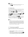
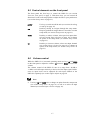
6.5 Control elements on the front panel
The front panel has four keys to control the PRE1 G3 (see section
'Overview front panel' on page 7). With these keys you can control all
functions as well as all setup options to adjust the unit to your preferences
(see section 'Setup menu' on page 21).
power
Use key to switch on/off the unit (see section 'Switching
on and off' on page 15).
set
Push key shortly to navigate through the setup menu.
Keep key pushed for longer than two seconds to exit the
setup menu (see section 'Setup menu' on page 21).
down
Push key to reduce volume, select previous input channel (see section 'Input selection' on page 19) or change
an option of the setup menu (see section 'Setup menu'
on page 21).
up
Push key to increase volume, select next input channel
(see section 'Input selection' on page 19) or change an
option of the setup menu (see section 'Setup menu' on
page 21).
6.6
Volume control
While the PRE1 G3 is in normal operating mode use keys up and down
on the front panel to adjust the volume. up increases, down decreases the
volume.
The volume control of the PRE1 G3 runs in a range from –80 dB to
+6 dB in real 1 dB steps relatively to the level of the input signal. Differences in input levels can be adjusted for each input channel of the
PRE1 G3 separately (see section 'Offset Adjust' on page 28.
Note
·
Use keys up and down also to change an option from the setup menu
(see section 'Setup menu' on page 21) as well as to select an input
channel (see section 'Input selection' on page 19).
17
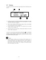
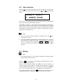
6.7
Display
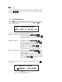
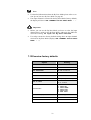
The display provides in the normal operating mode the following information:
1
2
5 INPUT FIVE
LEVEL –46+0dB
3
4
1
number of currently selected input channel, corresponds to the number printed above the input jack on the back panel (see section
'Overview back panel' on page 8).
2
name of the currently selected input channel, fully user-definable
(see section 'Channel name' on page 29).
3
current volume level in dB relative to the input level (see section
'Volume control' on page 17).
4
offset for input level of currently selected input channel (see section
'Offset Adjust' on page 28).
As soon as you enter the setup menu by pushing the set key, the display
changes to show information related to the selected menu item. For further display details refer to the description of each menu item in section
'Setup menu' starting from page 21.
Note
·
After 10 minutes without any user interaction the 'display saver' is
invoked automatically. The display then shows only the number of
the currently selected input channel and the current volume level.
Please refer to section 'Set Dim Level' on page 25 for further information on the 'display saver' mode.
18
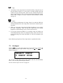
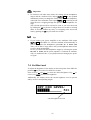
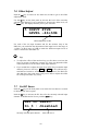
6.8
Input selection
Push the set key on the front panel once for less than two seconds, then
select the desired input channel with the keys up and down. The display
shows:
SELECT INPUT:
5 INPUT FIVE
The 2nd line of the display provides the number and the (user-definable)
name of the currently selected input channel.
The PRE1 G3 features a 'soft' input selection. During the switching of
inputs, first the volume is stepped down to –80 dB, followed by switching
off the outputs. Now the input section switches to the new input channel.
Afterwards the outputs are switched on again, and finally the volume is
stepped up to its original level.
Note
·
Leave the input selection function by holding down the set key
longer than 2 seconds.
·
Using the Audionet System Remote Control Harmony One, select an
input channel by simply pressing the corresponding key (see section
'Screen 1' on page 37), or use the keys Ch+ and Ch- to switch to
the next or previous input channel without using the Select Input
function.
6.9
Muting
Note
·
The muting function is only available through the Audionet System
Remote Control Harmony One.
Press key
of the Audionet System Remote Control Harmony One to
mute or un-mute your PRE1 G3.
Just as well as the input selection, the PRE1 G3 uses 'soft' muting, i.e.
volume is stepped down gently to -80 dB, then the outputs are switched
off. The display informs the user of a muted unit with the text MUTE in
the 2nd line. Even if the dim level is set to Off, the text is displayed.
To un-mute the PRE1 G3 press key
again. Here as well, the volume is
stepped up gently to its original level after switching on the outputs.
19
Note
·
While the unit is muted, you may of course select a different input
channel as described above. But the PRE1 G3 will stay muted until you
again to un-mute and restore the original volume
press the key
level.
·
If you turn up the volume by using the key up or Vol+ , while the
PRE1 G3 is muted, the muting function will be deactivated and the
new volume level set.
20
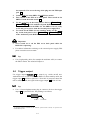
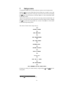
7
Setup menu
To adjust the PRE1 G3 to your preferences, please use the setup menu.
Push the set key on the front panel for less than two seconds to go to the
first item of the setup menu. Navigate to the next menu item, by pushing
the set again for less than two seconds. Below is a list of all menu items
of the setup menu.
After the last menu item you will leave the setup menu automatically. Of
course, you may leave the setup menu from each menu item by holding
the set key down for longer than two seconds. The PRE1 G3 will return
to the normal operating mode.
The order of items in the setup menu is:
ê*1
SELECT INPUT
ê
SET MONITOR
ê
SET HEADPHONES
ê
SET DIM LEVEL
ê
BALANCE ADJ.
ê
OFFSET ADJUST
ê
SET DC SERVO
ê
Channel name
ê
SET OUT 2 (SUB)
ê
SET AUTOSTART
ê
SET CHANNEL FOR BY-PASS MODE
Change any setting of a menu item by using the keys up and down on the
front panel.
*1
ê = push set key shortly (less than two seconds)
21
Tip
·
All settings of the setup menu can be dealt with by using the keys of
the front panel. However, if you prefer to change settings from the
comfort of your listening chair, please use the Audionet System Remote Control Harmony One. For more information about the remote
control and its usage see section 'Audionet System Remote Control'
on page 34.
Note
·
If you make no adjustments for longer than 12 seconds the PRE1 G3
will automatically leave the setup menu and return to normal operating mode.
·
While you are in the setup menu the display brightness is set to 100%
for better readability. After leaving the setup menu the display
brightness is automatically reset to its user selected level.
·
If you power down the PRE1 G3 to stand-by mode all settings are
stored automatically in the non-volatile memory of the unit. Even after disconnecting from mains the PRE1 G3 will still remember your
settings.
In the following all options of the setup menu are explained in detail.
7.1
Set Input
Push the set key on the front panel once for less than two seconds and
select than the desired input channel using the keys up and down. The
display changes to:
SELECT INPUT:
5 INPUT FIVE
The 2nd line of the display shows the number and the (user-definable)
name of the currently selected input channel.
See also section 'Input selection' on page 19.
22
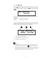
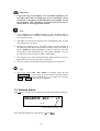
7.2
Set Monitor
Push the set key on the front panel twice for less than two seconds to get
to the settings of the monitor loop. Push the up key to activate the monitor loop. If you would like to deactivate the monitor loop, please push the
down key.
SET MONITOR:
active
The 2nd line of the display informs the user about the current status of the
monitor loop:
disabled
The monitor loop is disabled.
active
The monitor loop is active.
In normal operating mode, the symbol M at the end of the 1st display line
indicates an active monitor loop. Also, the input channel name is now
replaced by the (user-definable) name of the monitor loop.
1
2
3
5 TAPE MONITOR M
LEVEL –46+0dB
1
currently selected input channel
2
user-definable name for the monitor loop
3
indicator for active monitor loop
Note
·
If the monitor loop is active the current input channel stays selected.
But the signal from the monitor input 17 is routed to the outputs.
·
The name for the monitor loop is user-definable as well as the input
channel name (see section 'Channel name' on page 29). The name for
the monitor loop is restricted to 12 characters in length.
23
Tip
You can switch on/off the monitor loop much more comfortably by using
the key Monitor on screen page 2 of the Audionet System Remote
Control.
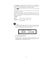
7.3
Set Headphones
Push the set key on the front panel three times for less than two seconds
to get to the headphones settings. Now use the keys up and down to select the desired option.
SET HEADPHONES:
HP off & Link on
The 2nd line shows the status of the headphones output:
HP off & Link on
Headphones output HEADPHONES 4 is disabled. The 'Audionet Link' output OUT 2 19
is switched on/off with the PRE1 G3 switching
on/off.
HP on & Link on
Headphones output HEADPHONES 4 is active. The 'Audionet Link' output OUT 2 19 is
also active as long the unit is switched on.
Use this option if you connect devices to the
'Audionet Link' output OUT 2 19 that are
supposed to be controlled via 'Audionet Link'
independently from the headphones setting.
HP on & Link off
Headphones output HEADPHONES 4 is active,
but the 'Audionet Link' output OUT 2 19 is always switched off.
Use this option if you would like to switch off
amplifiers, that are connected to the 'Audionet
Link' output OUT 2 19 , automatically while
you are using the headphones output.
The display indicates an active headphones output by the symbol
the 2nd line:
5 INPUT FIVE
LEVEL –46+0dB
indicator headphones output active
24
in
Important
·
In contrast to all other menu items, the settings for the headphones
output and the 'Audionet Link' output OUT 2 19 are not updated
immediately when you change the setting. This is to avoid amplifiers,
connected to the 'Audionet Link' output OUT 2 19 , switching on/off
while the user is stepping through the options of the headphones settings.
The selected option will be activated as soon as you leave the menu
by holding the set key down for longer than two seconds or waiting
about 12 seconds without any entry, or navigating to the next menu
item by pushing the set key less than two seconds.
Tip
·
If you connect your power amplifier to the 'Audionet Link' output
OUT 2 19 of the PRE1 G3, it will be switched off automatically as
soon as you select the headphones option HP on & Link off.
Thus, you are able to enjoy music with your headphones and need not
to worry about the amplifier.
In case you deactivate the headphones output by selecting the option
HP off & Link on, the power amplifier is switched on automatically via 'Audionet Link', so you playback music through your speakers again.
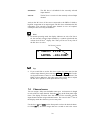
7.4 Set Dim Level
To adjust the brightness of the display on the front panel of the PRE1 G3
push the set key four times less than two seconds.
Now use keys up and down to select the desired brightness. Key up increases, key down decreases the brightness.
Additionally, the display shows the current brightness level in percent
and by a bar of corresponding length:
SET DIM LEVEL:
██████______ 50%
current brightness level in
25
Important
·
Long-term usage of the display set to maximum brightness (setting 100%) may cause extended signs of wear resulting in a decay
of contrast or brightness of individual dots in the display. Do not
use the display with a brightness set higher than the factory default of 50% over a longer period of time!
Note
·
Is the brightness set to Off the display is only on during setup or
volume adjustments. It switches off automatically several seconds after the last user entry.
·
The PRE1 G3 activates the 'display saver' automatically after 10 minutes without any user entry.
·
During active 'display saver', the display shows only the number of
the selected input channel and current volume level in the form of
In 4 -47dB. The display brightness is always reduced to 25%, and
the location of the information text will change randomly every 12
seconds to prevent any 'burn-in' effect of the display.
·
The 'display saver' is de-activated and the display returns to its normal mode as soon as any user entry is detected
·
The user cannot switch off the automatic 'display saver' function!
Tip
·
Get to the option Set Dim Level at anytime using the key
Dim Display on screen page 2 of the Audionet System Remote
Control Harmony One (see section 'Screen 2' on page 38). Use keys
Vol- and Vol+ to select desired brightness.
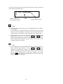
7.5 Balance Adjust
Push set key five times for less than two seconds. The display reads now:
BALANCE ADJ.: +0
-current balance setting in dB
Now adjust the balance by using the keys up and down.
26
Use the up key to shift the balance to the right. The 1st line of the display
shows the volume difference in dB between left and right channel. A
positive value means that the balance is shifted to the right.
Use the down key to shift the balance to the left. The value in the display
is now negative.
The PRE1 G3 allows the user to shift the balance up to 9 dB to the left or
the right in steps of 1 dB.
The 2nd line of the display visualises a balance shift with one or more
symbols. The orientation of the symbol represents the direction of the
balance shift, the number of symbols equals the amount of 1 dB steps the
balance was shifted.
Example:
►►►
balance shifted to the right by 3 dB
◄◄◄◄◄
balance shifted to the left by 5 dB
--
no balance shift
Note
·
In normal operating mode the PRE1 G3 indicates a balance shift by
the corresponding symbol in the 2nd line of the display. Thus you are
able to see at any time if the balance was shifted:
5 INPUT FIVE
► LEVEL –46+0dB
► = balance shifted to the right
◄ = balance shifted to the left
·
A balance shift is carried out internally by attenuating the corresponding channel, i.e. if the balance is shifted to the right, the level of
the left channel is attenuated and vice versa.
27
7.6 Offset Adjust
Push the set key six times for less than two seconds to get to the offset
adjustment menu.
Use the up key on the front panel to increase the level of the currently
selected input channel. If you would like to decrease the offset level, use
the down key. The display informs you of your selection:
5 INPUT FIVE
LEVEL –46+3dB
offset adjustment in dB
For each of the six input channels and for the monitor loop of the
PRE1 G3 you can define the adjustment of the input level in the range of
–9 dB to +9 dB in steps of 1 dB to match the different output levels of
sources connected to the PRE1 G3.
Tip
·
To adjust the offset of the monitor loop you first have to activate the
loop (see section 'Set Monitor' on page 23). Now you adjust the offset
as described above for the offset of the input channels.
·
If you would like to adjust the input level offset for just another input
channel, please use the keys Ch+ and Ch- of the Audionet System Remote Control to switch to the desired channel. The PRE1 G3
does not leave the setup menu, and you are able to adjust the offset
for each input channel very easily.
7.7
Set DC Servo
Push the set key on the front panel seven times for less than two seconds
to adjust the DC Servo option.
Push the up key to activate the DC Servo for the currently selected input
channel. To disable the DC Servo push the down key.
SET DC SERVO:
In 3 : disabled
currently selected input channel
status DC Servo
28
disabled
The DC Servo is disabled for the currently selected
input channel
active
The DC Servo is active for the currently selected input
channel.
Activate the DC Servo if the source connected to the PRE1 G3 holds a
high DC component in its output signal. The DC Servo eliminates the DC
component. The currently selected input channel is now AC-coupled.
Usually the DC Servo may be disabled.
Note
·
In normal operating mode the display indicates an active DC Servo
for the currently selected input channel by a symbol right beside the
volume level in the 2nd display line. Thus you can see at any time if
the DC Servo is active:
DC Servo is active
5 INPUT FIVE
LEVEL –46+0dB*
Tip
·
If you would like to set the DC Servo option for more than just the
current input channel, please use keys Ch+ and Ch- of the Audionet System Remote Control to select the desired input channel. The
PRE1 G3 does not leave the setup menu, and you are able to adjust
the DC Servo option for each input channel very easily.
7.8
Channel name
You can assign a fully user-definable name up to 14 characters in length
to each of the six input channels. Push the set key on the front panel eight
times. The display will then show the number of the currently selected
input channel and the assigned channel name. The cursor in the 2nd line of
the display marks the character you now may alter.
Use the keys up and down on the front panel to select the desired character. Hold set key down for longer than two seconds to move the cursor
29
one step to the right. After the last position the cursor wraps around and
starts at the first position again.
4 CD PLAYER
▲
number of currently
selected input channel
cursor
assigned channel name
Note
·
The name of the monitor loop is also user-definable (up to 12 characters in length).
To edit the name of the monitor loop you first have to activate the
loop (see section 'Set Monitor' on page 23). Then edit the name of the
monitor loop as described above for editing the input channel name.
·
If the monitor loop is active, you are able only to edit the name of the
monitor loop, even if you use the keys Ch+ and Ch- of the
Audionet System Remote Control to change the input channel. You
have to deactivate the monitor loop first, before you are able to edit
the input channel names again.
Tip
·
If you would like to edit the channel name for more than just the currently selected input channel, use keys Ch+ and Ch- of the
Audionet System Remote Control to switch to the desired input
channel. The PRE1 G3 does not leave the setup menu, and you are
able to edit the channel name for other input channels very easily.
Press key
of the Audionet System Remote Control to advance the
cursor one position to the right.
30
7.9
Set Out 2 (Sub)
Push the set key nine times for less than two seconds to select the format
of the output signal of Cinch output OUT 2 7 .
Push the up key on the front panel to select the mode Subwoofer for the
output OUT 2 7 . If you would like to select the mode Left & Right
push the down key.
SET OUT 2 (SUB):
Subwoofer
selected mode for output OUT 2 7
Left & Right
Left and right channel are routed to the Cinch output
OUT 2 7 . Therefore, output OUT 2 7 offers the
same signal as output OUT 1 6 .
Subwoofer
The mono sum signal of channels left and right is
output on both jacks of output OUT 2 7 for driving
a subwoofer.
Note
·
In mode Subwoofer the mono sum signal is composed by the formula: ½*(Left + Right).
Tip
·
If your subwoofer offers only one cinch input jack, select mode Subwoofer in the menu Set Sub Out and connect one of the jacks of
output OUT 2 7 to the input of your subwoofer.
·
Consult the manual of your subwoofer.
·
If you would like to use the output OUT 2 7 as fully-fledged stereo
output (e.g. for driving power amplifiers), select mode Left &
Right.
31
7.10 Set Autostart
Push the set key ten times for less than two seconds to get to the
Autostart option.
Push the up key on the front panel to activate the Autostart function. If
you like to deactivate the Autostart function push down key.
SET AUTOSTART:
active
status of the Autostart function
disabled
The Autostart function is disabled. After switching on the
mains switch 1 on the back panel, the PRE1 G3 enters
the stand-by mode. You have to use the power key on the
front panel or keys Power On or Power Toggle on
the Audionet System Remote Control Harmony One to
switch on the unit into normal operating mode*).
active
The Autostart function is active. As soon as you connect
the PRE1 G3 to mains (i.e. use the mains switch 1 on
the back panel) the unit starts up automatically to normal
operating mode. Use this setting for timer controlled operations.
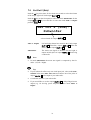
7.11 Set Channel for By-Pass Mode
Push the set key eleven times for less than two seconds to enter the option for selecting the input channel in By-Pass Mode.
Use keys up and down on the front panel to select the input channel you
would like to use in By-Pass Mode.
SET CHANNEL FOR
BY-PASS MODE: 3
dot
input channel no. 3 is used in By-Pass Mode
*)
or switched on/off by Activities on the Audionet System Remote Control; see separate user's
manual Harmony One
32
Note
·
For detailed information about the By-Pass Mode please refer to section 'Special function By-Pass Mode' on page 40.
·
If no input channel is selected for the By-Pass Mode (factory default),
the display will show: SET CHANNEL FOR BY-PASS MODE: - -.
Important
·
Before you can use the By-Pass Mode you have to select the input
channel that is used for the By-Pass Mode. Otherwise the PRE1 G3
issues the warning: No input for By-Pass selected.
·
For safety reasons the factory default settings have no input channel
selected for By-Pass Mode (display: SET CHANNEL FOR BY-PASS
MODE: - -).
7.12 Overview factory defaults
Option
Setting
SELECT INPUT
INPUT TWO
SET MONITOR
disabled
SET HEADPHONES
HP off & Link on
SET DIM LEVEL
50%
BALANCE ADJ.
- -
OFFSET ADJUST
0 dB (for all input channels)
SET DC SERVO
In 1-5: disabled
In 6: active
Channel name
1:
2:
3:
4:
5:
6:
SET OUT 2 (SUB)
Left & Right
SET AUTOSTART
disabled
SET CHANNEL FOR BY-PASS MODE
- -
33
BALANCED
INPUT TWO
INPUT THREE
INPUT FOUR
INPUT FIVE
TAPE INPUT
8
Audionet System Remote Control
Every function of the PRE1 G3 is accessible via the Audionet Systemfernbedienung Harmony One. Additionally, up to 14 other devices can be
controlled by the Harmony One.
Press key Devices to enter Device Mode. The display now lists all
devices included in the current configuration of the Harmony One. Select
PRE1 G3 from the list to set the Harmony One to controlling the
PRE1 G3. The Device Mode gives you access to all the possible commands to control your PRE1 G3. The following explains all these commands in detail.
Important
·
During everyday use, you should never need to use the Device Mode
of your Harmony One, but control the PRE1 G3 (and other devices of
your audio setup) by customizing your Activities. For detailed information on how to customize and use Activities on your Harmony
One please consult the separate user's manual that came with your
Harmony One.
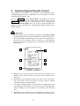
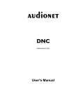
1
2
My Activities:
Mi 14:51
1/2 pages
Listen to CDs
Watch a DVD
3
3
CD with VIPG3
Options
Devices
4
5
1
Power key for use with Activities, turns all devices off that are included into the current Activity. See separate user's manual of Harmony One.
2
Depending on the operational mode, the touch screen of the Harmony One shows a list of Activities or Devices, help or infrared
commands and any available listings.
3
If a menu or listing stretches over more than one screen page, use the
corresponding arrow buttons to go to the next or previous page of the
menu or listing. (see also separate user's manual of the Harmony
One).
4
Devices key, lists all the devices on the display, and allows you to
select and directly control any device included in the configuration of
34
the remote control (see separate user's manual of Harmony One). Select PRE1 G3 to enter Device Mode for controlling the PRE1 G3.
5
Activities key: Press this key to view a list of Activities you have
added. Press the button next to the Activity you want to select, and
the Harmony One will control your entertainment system (see separate user's manual of Harmony One).
Important
·
is only available for Activities. In Device
The Power key
Mode the Power key has no function.
·
Even without using an Activity, the user is able to control all
functions of the PRE1 G3 using the Harmony One in Device
Mode.
·
The keys described below to control the PRE1 G3 refer to the
factory default programming of the Audionet System Remote
Control Harmony One. Understandably, any changes done to this
setup by the user cannot be discussed here.
Tip
·
In order to switch the PRE1 G3 on/off, without using an Activity,
please use the keys Power On , Power Off or PowerToggle
on screen 3 (see section 'Screen 3' on page 39). Of course, it is possible to control the PRE1 G3 without any Activity, but to tap the full
potential of the Harmony One you need to configure Activities customized to your needs (please refer to separate manual of the remote
control Harmony One).
Note
·
Please read the separate user's manual to your Audionet system remote control Harmony One. Activities, Devices and Device Mode as
well as customizing the remote control are discussed there.
35
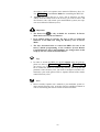
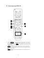
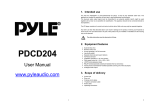
8.1 Key assignment PRE1 G3
PRE1 G3:
Mi 14:51
1/3 pages
Balanced
Input
Input Two
Input Three
Input Four
Tape Input
Phono Input
Current
Activity
Devices
1
2
3
4
5
6
7
1
Use key Menu to navigate through the setup menus. This key has
the same function as key set on the front panel (see section 'Setup
menu' on page 21) or key Set on screen page 2 (see section 'Screen
2' in page 38).
2
Vol+ , increases the volume of the PRE1 G3, also for selecting setup options or input channels. This key has the same function as key
up on the front panel.
3
Ch+ , switches to the next input channel (see section 'Input selection' on page 19).
36
4
Vol- , decreases the volume of the PRE1 G3, also for selecting setup options or input channels. This key has the same function as key
down on the front panel.
5
Ch- , switches to the previous input channel (see section 'Input selection' on page 19).
6
, mutes the PRE1 G3 (see section 'Muting' on page 19).
7
Digit keys for direct input selection (see section 'Input selection' on
page 19).
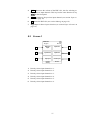
8.2
Screen 1
PRE1 G3:
Mi 14:51
1/3 pages
1
Balanced
Input
Input Two
2
3
Input Three
Input Four
4
5
Tape Input
Phone Input
6
Current
Activity
Devices
1
Directly selects input channel no. 1.
2
Directly selects input channel no. 2.
3
Directly selects input channel no. 3.
4
Directly selects input channel no. 4.
5
Directly selects input channel no. 5.
6
Directly selects input channel no. 6.
37
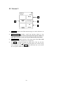
8.3 Screen 2
PRE1 G3:
Mi 14:51
2/3 pages
2
By-Pass
Mode
Current
Activity
Monitor
1
Dim Display
3
Set
4
Devices
1
Monitor switches on/off the monitor loop (see section 'Monitor' on
page 12).
2
By-Pass Mode switches on/off the By-Pass Mode of the
PRE1 G3. Please read section 'Special function By-Pass Mode' on
page 40 first, before you use the special function By-Pass Mode.
3
Dim Display jumps directly to the setup menu item Set Dim
Level (see section 'Set Dim Level' on page 25).
4
Use Set to navigate through the setup menus. This key has the
same function as the set key on the front panel (see section 'Setup
menu' on page 21) or key Menu of the Harmony One (see section
'Key assignment PRE1 G3' on page 36).
38
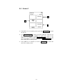
8.4 Screen 3
PRE1 G3:
Mi 14:51
3/3 pages
2
Power On
1
Power Off
3
Power
Toggle
Current
Activity
Devices
1
If the PRE1 G3 is in stand-by mode, press key Power On to switch
the unit on.
2
Use Power Toggle to switch on/off the PRE1 G3. This key has
the same function as the power key onthe front panel. If the
PRE1 G3 is in stand-by mode, Power Toggle switches on the
unit. If the PRE1 G3 is already switched on, Power Toggle switches off the unit to stand-by mode.
3
If the PRE1 G3 is witched on, use key Power Off to switch the
unit off to stand-by mode.
39
9
Special function By-Pass Mode
The By-Pass Mode was primarily intended to integrate the overwhelming
sound quality of the PRE1 G3 into an existing home cinema setup or to
expand an existing excellent stereophonic system based on the PRE1 G3
to a complete home cinema setup without missing out on the qualities of
the PRE1 G3. To realise this kind of setup, please proceed as follows:
1. Connect your home cinema pre amplifier according to its user's manual.
2. Connect the output for the front channels Left and Right not to the
power amplifier but to one of the free inputs of the PRE1 G3.
3. Now connect the outputs of the PRE1 G3 to the corresponding power
amplifier for the channels Left and Right.
4. Use menu item 'Set Channel for By-Pass Mode' of the setup menu of the
PRE1 G3 to select the input channel for By-Pass Mode you connected the outputs Left and Right of the home cinema pre amplifier
to.
5. Connect now all high quality 2-channel analog sources to the remaining inputs of the PRE1 G3.
6. Connect your DVD player to your home cinema pre amplifier as
usual.
Use the PRE1 G3 to listen to high quality analog sources. If you would
like to use your home cinema system activate the By-Pass Mode of the
PRE1 G3 and use your home cinema pre amplifier as usual.
Important
·
The activate the By-Pass Mode you need a Audionet System Remote Control Harmony One
·
Please read the complete section about the special function ByPass Mode first before you use this function in order to prevent
maloperations and possible damage to your audio system and/or
hearing.
·
By factory default no input channel is selected for the By-Pass
Mode. Use menu option 'Set channel for By-Pass Mode' to select
desired input channel for the By-Pass Mode. If no input channel
is selected and you try to invoke the By-Pass Mode the PRE1 G3
issues the warning: No input for By-Pass selected (see
section 'Set Channel for By-Pass Mode' on page 32).
Is the By-Pass Mode active the volume control of the PRE1 G3 is bypassed. The PRE1 G3 passes through the input signal to the outputs with
its full level.
40
Please use setup option 'Set Channel for By-Pass Mode' to select which of the
six input channels of the PRE1 G3 is fed through to the outputs if ByPass Mode is active.
Important
·
First, select the input channel used for By-Pass Mode (see section
'Set Channel for By-Pass Mode' on page 32), before you activate the
By-Pass Mode for the first time.
Activate the special function By-Pass Mode of your PRE1 G3 by pressing
the key By-Pass Mode of the Audionet System Remote Control. The
signal at the input channel selected for By-Pass Mode operations is
passed through the PRE1 G3 at a level of 0 dB (i.e. no change in volume
level) to the outputs.
Important
·
Please check the correct connection and setup before you use the
By-Pass Mode for the first time. The input signal will be passed
through to the outputs at full level!
As soon as the By-Pass Mode is activated, the PRE1 G3 will ignore all
control commands coming from the keys on the front panel or remote
control (exceptions see below)!
Important
There are only two possibilities to disable the By-Pass Mode:
1.
Press key By-Pass Mode of the Audionet System Remote Control. The PRE1 G3 switches back to the input channel selected before resetting the volume to its prior level.
2.
Push the power key on the front panel or the buttons Tasten
Power Toggle or Power Off . on the Audionet System Remote
Control. The PRE1 G3 switches off to stand-by mode.
Note
·
If you leave the By-Pass Mode by pushing the power key on the
front panel, this mode will not be saved, i.e. if you switch on the
PRE1 G3 again, the unit will switch to the last saved input channel
selection and not to the By-Pass Mode. If you would like to use the
By-Pass Mode again, press key By-Pass Mode of the Audionet
System Remote Control Harmony One.
41
10 Technical information
10.1 Design
With circuits consequently designed using SMD miniature technology
and shortening all signal paths to a minimum the high frequency characteristics were optimized. Ground pathways run in a star-shaped pattern
converging in one central location. The circuit design is optimized capacitively and inductively. A powerful microprocessor controls and
monitors the system. The analog section and control unit are galvanically
separated by opto-couplers, the digital section also spatially separated.
10.2 Power supply
A 50 VA toroid transformer powers high-current capacitors with a total
capacity of 20,000 μF. Two fast, discrete pre-regulators smooth and stabilize the supply voltages. Additionally the voltages for the input and output stage each are smoothed locally by two discrete and ultra-fast regulators. The digital section has a separate power supply.
10.3 Circuitry
All operational amplifiers optimized and embedded in a discrete circuitry.
The driver stage operates distortion-free in symmetric class A mode.
Gold-coated precision relays switch the input signal and ground. Volume
and balance is controlled, free of any electro-mechanical component, via
precision resistor networks that are switched electronically and linearized
in real-time. The resolution of the volume control circuit is 1 dB.
10.4 Handling
A microprocessor controls and monitors all functions. A two line, 16digit display informs the user about all operating modes and makes it
easy to adjust the PRE1 G3 to the user's preferences. The unit also features user-definable channel names and input level adjustment for each
channel. Two 'Audionet Link' outputs facilitate easy daisy-chaining of
Audionet devices for remote switching on/off via 'Audionet Link'. Each
input channel features a user selectable DC Servo to eliminate DC components on source signals. Furthermore a monitor loop for an additional
recorder, decoder etc. is present.
The PRE1 G3 can be equipped with the Audionet system remote control
Harmony One, a phono module for MM- and MC-systems, and an external power supply, the EPS.
42
11 Security advice
Important
·
Avoid packaging material, especially plastic bags, coming into children's hands!
·
Store and operate the unit in a dry room at a reasonable room temperature only!
·
Avoid moisture, any liquids, dirt or small objects getting into the
unit!
·
Set up the unit in a sufficiently ventilated environment!
·
Do not cover the unit!
·
Do not open the unit. Unauthorised opening will void warranty!
·
Do not short-circuit the outputs!
·
During connecting or removing the PRE1 G3 to/from sources and/or
power amplifiers all units have to be switched off to prevent damage
of the PRE1 G3 or any of the other connected units.
·
Use dry cloth for cleaning!
We would like to wish you many exciting listening experiences with your
new Audionet product.
If you still have any questions, do not hesitate to ask your competent
Audionet dealer or contact us directly
43
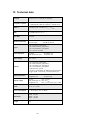
12 Technical data
Function
microprocessor controlled pre-amplifier
Frequency response
0 – 3,000,000 Hz (-3 dB), DC coupled
2 – 3,000,000 Hz (-3 dB), AC coupled, 1st order DC servo
THD+N
>108 dB, 20 Hz - 20 kHz, for Vin = 5 VRMS
SNR
> 120 dB relative to Vin,max
Slew Rate
10 V/μsec
Channel separation
between channels
between inputs
Inputs
5 pair Cinch line, gold plated
1 pair XLR balanced, gold plated
1 pair Cinch Monitor, gold plated
5-pin connector for EPS
Input impedance
line input
XLR (balanced) input
Input voltage
max. 5 VRMS
Outputs
1 pair Cinch line, gold plated
1 pair XLR balanced, gold plated
1 pair Cinch Rec Out, gold plated
1 pair Cinch Monitor, gold plated
2 Audionet Link, optical
1 connector, gold plated, for additional earth connection
1 trigger output, 12 Volts DC, 3.5mm telephone jack
Output impedance
line and balanced out
headphones out
Output voltage
line out
max. 8 VRMS
XLR (balanced) out max.16 VRMS
headphones out
max. 8 VRMS (max. gain = 6 dB)
Mains
230 V, 50…60 Hz
Power consumption
< 1 W Stand-by, max. 30 Watts
Dimensions
Width 430 mm
Height 72 mm
Depth 420 mm
Weight
6 kg
44
> 100 dB @ 20 kHz
> 108 dB @ 20 kHz
82 kOhms real
15 kOhms real
22 Ohms real
47 Ohms real
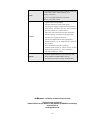
Front: brushed aluminium, black anodised, white print
or aluminium 'nature', anodised, black print
Finish
Display: red or blue
Top cover: brushed aluminium, microlised
Chassis: steel, black coated
Features
Options
-
remote control (not included)
-
automatic detection of main polarization
-
separate power supply for digital and analog sections
-
electronically switched and real time linearised
precision resistors for volume control
-
audio and control functions optically decoupled
-
full DC coupling, no capacitors in the signal path
-
selectable AC coupling via DC servo
-
separate level adjustment for each input channel
-
By-Pass function (e.g. for integration into home cinema systems)
-
Auto start function for timer operations
-
Audionet Link outputs for remote control of other
Audionet components (e.g. power amplifiers)
-
selectable headphones output
-
Audionet System Remote Control Harmony One
-
Phono module for MM and MC pickups
-
external precision power supply Audionet EPS
Errors and omissions excepted. Specifications and design are subject to changes without prior notice.
audionet is a trademark of Idektron GmbH & Co KG
Engineered and produced by:
Idektron GmbH & Co. KG, Herner Str. 299, Gebäude 6, 44809 Bochum, Germany
www.audionet.de
[email protected]
45