1
Phono Preamplifier
&
External Power Controller
User's Manual
1
2
Contents
1
Preface..........................................................................................5
1.1
Included.........................................................................................6
1.2
Transport .......................................................................................6
2
Overview front panels.................................................................7
3
Overview back panels .................................................................8
3.1
EPC back panel .............................................................................8
3.2
PAM G2 back panel......................................................................9
4
Installation and power supply..................................................10
4.1
Placement ....................................................................................10
4.2
Mains connection ........................................................................10
4.3
Connection of EPC & PAM G2 ..................................................11
4.4
Connection diagram ....................................................................13
4.5
Audionet Link .............................................................................14
5
Inputs and outputs ....................................................................15
5.1
Inputs...........................................................................................15
5.2
Outputs ........................................................................................15
6
Operating ...................................................................................16
6.1
Powering up ................................................................................16
6.2
Switching on and off ...................................................................16
6.3
Mains phase detection .................................................................17
6.4
Using Audionet Link...................................................................17
6.5
Control elements on the front panels ..........................................18
6.5.1
PAM G2 control elements...........................................................18
6.5.2
EPC control elements..................................................................18
6.6
Display ........................................................................................19
6.7
Input selection .............................................................................20
7
Audionet System Remote Control ...........................................21
7.1
Key assignment EPC...................................................................23
7.2
Screen 1.......................................................................................24
7.3
Screen 2.......................................................................................25
3
8
Setup menu ................................................................................26
8.1
Set Gain.......................................................................................27
8.2
Set Resistance..............................................................................28
8.3
Set Capacitance ...........................................................................28
8.4
External input resistance (Set Rext) ............................................29
8.5
External input capacitance (Set Cext) .........................................30
8.6
Set Dim Level .............................................................................30
8.7
Set Display ..................................................................................32
8.8
Channel name..............................................................................32
8.9
Set Autostart................................................................................32
9
Matching the pick-up's electrical characteristic ....................34
9.1.1
MM Systems ...............................................................................34
9.1.2
MC Systems ................................................................................34
9.1.3
Typical setups..............................................................................35
9.2
Factory defaults ...........................................................................35
9.3
Further adjustments .....................................................................35
9.3.1
Adjusting the input capacity........................................................35
9.3.2
Resistance reduction....................................................................36
10
Security advice...........................................................................37
10.1
Technical data - PAM G2 ...........................................................38
10.2
Technical data - EPC...................................................................39
4
1
Preface
The Audionet Team congratulates you on your purchase of these units.
Audionet components are no marketing products, they are authentic.
Conceived and developed with scientific inspiration, professional engineering expertise and a passion for achieving the perfect sound. They are
unique creations designed to inspire musical enjoyment and have an excellent reputation amongst all connoisseurs throughout the world. Each
and every one of our precision-manufactured devices are individually
crafted at our Bochum works by our experienced and passionate workforce.
But before you start listening to your new Audionet PAM G2 and EPC,
please read this manual carefully so you are able to use and enjoy all
functions of these units without drawback on music quality.
5
1.1 Included
Included you will find the following items:
·
the phono preamplifier PAM G2
·
the external power controller EPC
·
the user's manual (that you are currently reading)
·
one EPS/EPC connection cable (7-pin)
·
one or two DB-25 connection cables (depending on the number of
input channels of the PAM G2)
·
one standard mains cord
·
one green-yellow cord for an additional earth connection
1.2 Transport
Important
·
Please transport the PAM G2 and EPC only in the included packages.
·
Always use the plastic bags to prevent scratches on the casing.
·
Please allow the PAM G2 and EPC to adapt to the climatic conditions in your listening room before you switch on the units for the
first time after transport.
6
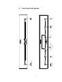
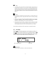
power
key EPC
power
key PAM G2
set
key
IR remote control
receiver
Display
down
key
up
key
input
key
2
Overview front panels
7
1
8
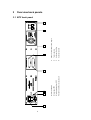
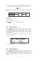
Mains switch EPC
Mains input EPC
Marking mains phase EPC
Phono Control Bus socket, input 1
6
7
8
3
5
2
4
4
3
2
1
6
Audionet Link In
Audionet Link Out
7-pin connector
Phono Control Bus socket, input 2
5
7
8
3
Overview back panels
3.1 EPC back panel
9
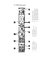
20 RCA input for additional input resistance or
input capacitance on input 1, left/right
16 Marking mains phase PAM G2
12 RCA output, left/right
RCA input no. 1, left/right
19 RCA input for additional input resistance or
input capacitance on input 2, left/right
16
15 Mains input PAM G2
15
11 RCA input no. 2, left/right
14
18 Balanced (XLR) output, left/right
13
14 Phono Control Bus socket, input 1
12
17
10 Earth connectors for turntables
11
18
17 Phono Control Bus socket, input 2
10
19
13 7-pin EPC connector
9
9
20
3.2 PAM G2 back panel
4
Installation and power supply
Important
·
For connecting or removing the EPC to/from the PAM G2, both
units and all other units of your audio system have to be switched off
to prevent damage of any of these devices.
·
Please make sure that all cables are in absolute best conditions!
Broken shields or short-cut cables could damage the units.
4.1 Placement
Important
·
Place the EPC to the right or at least 20 cm above/below of the
PAM G2.
·
It is recommended to place the EPC and PAM G2 into a high quality
rack or onto a stable table.
·
Do not expose the units to direct sunlight.
·
Do not cover the ventilation slots.
·
Do not place the EPC or PAM G2 in close range to heat sources like
radiators.
·
Do not place the EPC or PAM G2 on top of other units, especially
not on top of power amplifiers, preamplifiers or similar that produce
heat. The units could suffer damage from thermal overload.
·
Do not use the units in places where it is exposed to vibrations.
·
Do not place the units close to loudspeakers or into the corner of a
room where it is exposed to high levels of sonic energy, which might
reduce the sound quality of the units.
4.2 Mains connection
The mains input 2 * is on the back panel of the EPC. To connect the unit to
mains use the included mains cord. If you prefer to use a different power
cord make sure that it meets the specifications for your home country.
*
see numbers in section 'Overview back panel' on page 8.
10
Important
·
Do not connect the PAM G2 to mains! This would compromise the
quality of audio performance. The power supply of the PAM G2 is
provided by the EPC via the 7-pin EPS/EPC cable. Use only one
mains cord to connect the EPC to mains. For this reason, only one
mains cord is included.
Important
·
The electrical specifications of your home country must meet the
electrical specifications printed onto the back panel.
·
The EPC is a Class I unit and must be earthed. Please ensure a stable
earth connection. Phase ('hot' pin) is marked on the back panel
("PHASE") 10
·
Never pull the mains plug while the EPC is switched on! Before you pull
the mains cord off its socket 2 at the back panel, power down the unit
to stand-by mode and switch off the unit using mains switch 1 .
Only in cases of extended absence – like vacations – or if massive trouble
on the mains power is to be expected you should switch off the EPC from
the mains using the mains switch 1 . To disconnect the unit completely
from mains pull the mains plug.
Tip
·
The use of high quality mains cords (e.g. Audionet P10) could improve sound quality. Ask your local dealer for more information.
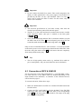
4.3 Connection of EPC & PAM G2
For the connection of the EPC and PAM G2, a 7-pin EPC/EPS connection cable and one or two DB25 cables are needed (depending on the
input channels of the PAM G2). A schematic of the connected devices
can be found on page 13.
To connect both units, follow these steps:
1. Make sure both PAM G2 and EPC are switched off and disconnected
from the mains.
2. Connect the EPC and PAM G2 with the included 7-pin EPC/EPS
connection cable from socket 6 of the EPC to the corresponding
socket 13 on the back panel of the PAM G2. The shape of the plug
prevents any wrong polarity.
11
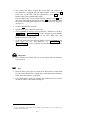
3. Now connect the Phono Control Bus of the EPC and PAM G2. If
your PAM G2 is equipped with one input channel, connect socket 4
at the rear of the EPC with the appropriate socket 14 of the
PAM G2 using the included DB25 cable.
If your PAM G2 has a second input channel, connect socket 5 at the
rear of the EPC with the appropriate socket 15 of the PAM G2 using
the second included DB25 cable (see section "Connection diagram"
on page 13).
4. Connect only the EPC to mains.
5. Switch on the EPC at the back panel first.
6. Use key power at the front panel of the EPC / PAM G2 or the keys
Power On or Power Toggle *) of the Audionet System Remote
Control Harmony One to switch on the EPC. Both, EPC and
PAM G2 are now ready to use.
7. To switch off the EPC into stand-by mode, use the key power on the
front panel of the EPC / PAM G2 or
Power Off
or
Power Toggle *) of the Audionet System Remote Control Harmony One.
Important
·
Never switch on or off the EPC on its back panel while the PAM G2
is switched on.
Tip
·
Place the EPC to the right or at least 20 cm above/below of the PAM
G2. Increasing the distance of both units, will minimize the influence
of the mains transformers in the EPC.
·
Use a high quality cable (for example the Audionet P10) to connect
the EPC to mains. The sound will improve.
*)
or use a corresponding Activity that you customized on your Harmony One (see separate user's
manual to the Harmony One).
12
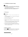
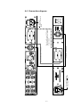
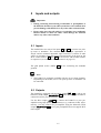
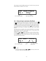
Power supply for both units.
Only one power cord is needed.
ur ein Netzkabel benötigt
7-pin EPS/EPC connection cable
Phono Control Bus, input1 - DB25 cable
Phono Control Bus, input2 - DB25 cable
Only needed if the PAM G2 is equipped with
two input channels
No cable required!
The PAM G2 is powered by
the EPC
4.4 Connection diagram
13
4.5 Audionet Link
For your convenience, the EPC can be controlled remotely by one of
Audionet's multi channel preamplifiers (e.g. MAP or MAP 1) as well as
one of Audionet's stereo preamplifiers (e.g. PRE G2, PRE 1 G3) using
the Audionet Link interface.
You only need a optical 'Toslink' cable to connect the Audionet Link
output of your Audionet preamplifier to the Audionet Link input IN 8 of
the EPC.
In case you would like to automatically switch on/off further Audionet
units in your system using the Audionet Link interface, please connect
the Audionet Link output OUT 7 of your EPC to the Audionet Link
input of the next Audionet unit (e.g. power amplifier, tuner, CD player
etc.) using a simple 'Toslink' cable.
Note
·
The 'switch on' signal is issued to any further Audionet units daisy
chained to the Audionet Link output of your EPC with a little delay
to avoid all units switching on at the same moment, which could
cause an overload of your mains fuse.
14
5
Inputs and outputs
Important
·
During connecting and removing of turntables or preamplifiers to
the PAM G2 all units of your audio system have to be switched off to
prevent damage of the PAM G2 or any of the other connected units.
·
Please make sure that all cables are in absolute best conditions!
Broken shields or short-cut cables could damage the PAM G2
and/or any other connected unit.
5.1 Inputs
The PAM G2 has two stereo line inputs 9 and 11 to connect two pickup arms or turntables. The maximal adjustable input capacitance is
420 pF and the minimal adjustable input resistance is 100 Ω. If other
values are needed to meet the electrical characteristic of the pick up, the
RCA sockets C/R ext. 19 and 20 can be used to add external resistors
or capacitors (see section 'Further adjustments' on page 35).
The gold plated screws (GND) 10 are for connecting the turntable
grounds.
Note
·
The PAM G2 is optionally available with one or two input channels.
Depending on the model, one or two pick-up arms or turntables can
be connected.
5.2 Outputs
The PAM G2 is equipped with one RCA output LINE 12 as well as one
balanced (XLR) output BALANCED 18 for the left and right channel to
connect the unit to your preamplifier.
Use the RCA output LINE 12 to connect the PAM G2 to your preamplifier using high quality interconnectors (e.g. Audionet C100). Alternatively, you may connect the pre-amplifier using the balanced (XLR)
outputs BALANCED 18 in case your preamplifier does not support RCA
(line) inputs.
15
6
Operating
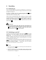
6.1 Powering up
First of all, please make sure your EPC and PAM G2 are connected correctly (see section 'Mains connection' on page 10 and 'Connection of EPC
& PAM G2' on page 11).
The EPC is a stand-by unit. Please operate the mains switch 1 on the
back panel. The display shows a welcome message for a brief moment.
After that the EPC is in stand-by mode.
Only in cases of extended absence (like vacations) or if massive trouble
on the mains power is to be expected (e.g. thunder storms) it is recommended to disconnect the EPC from the mains. While the EPC is in
stand-by mode, operate mains switch 1 on the back panel. To disconnect
the EPC from mains completely, you have to pull the mains cord off the
mains socket 2 .
Important
·
Never pull the mains plug while the EPC and PAM G2 are
switched on! Before you pull the mains cord off its mains socket
2 , power down the EPC to stand-by mode and switch off the
unit using mains switch 2 at the back panel.
6.2 Switching on and off
To power up the EPC from stand-by mode, press the power key on the
front panel of the EPC / PAM G2. The EPC displays the message
Waking up.... In case the mains plug has the incorrect polarization a
warning will appear in the display (see section 'Mains phase detection' on
page 17). After that the EPC and the connected PAM G2 are in normal
operating mode and ready to use.
If you would like to switch off the EPC and the PAM G2, please press the
power key on the front panel of the EPC / PAM G2. The display shows
the message Going to sleep. .. and the EPC enters the stand-by
mode. The connected PAM G2 is also turned off.
Note
·
You can also use the power key on the front panel of the PAM G2 to
switch both units on or off.
·
Of course, you may switch on/off the EPC with the Audionet System
Remote Control Harmony One. For detailed information please refer
to section 'Screen 2' on page 25.
16
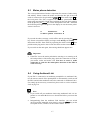
6.3
Mains phase detection
The correct polarization of mains is important for reasons of audio clarity
and stability. Please connect the mains cord that the 'hot' pin of the wall
outlet is connected to the pin marked 'phase' 3 of the mains input 2 on
the back panel. The EPC recognizes the incorrect polarization of the
mains plug automatically. Right after switching on the unit from stand-by
mode by pressing the power key on the front panel of the EPC / PAM G2
the following message will appear in the display in case the mains polarization is incorrect:
►
Attention:
◄
► Mains phase incorrect ◄
If you read the above message, switch off the unit by pressing the power
key. Please wait until the display no longer reads Going to sleep....
Disconnect the EPC from mains by operating the mains switch 1 . Now
pull the mains plug and re-insert it into the mains socket rotated by 180°.
If you switch on the unit again, the warning should not appear now.
Important
·
If the EPC issues the mains polarization warning or no warning at all
for both positions of the mains plug, check the connection to earth of
your mains socket and mains cord. You have to ensure a stable
connection to earth for the mains phase detection of the EPC to
work correctly!
6.4
Using Audionet Link
If your EPC is connected to an Audionet preamplifier via Audionet Link,
use the remote control of the preamplifier to automatically switch on/off
the EPC (and all other Audionet units also connected via Audionet Link).
For setting up the necessary connections please refer to section 'Audionet
Link' on page 14.
Note
·
If you switch off your Audionet chain using Audionet Link, it is important to wait until all devices are shut down before you restart the
system.
·
Independently from the Audionet Link interface, you can switch
on/off your EPC manually at any time by using the power key on the
front plate of EPC, PAM G2 or the remote control.
17
6.5 Control elements on the front panels
6.5.1
PAM G2 control elements
The front panel has two keys to control the PAMG2 (see section
'Overview front panels' on page 7).
power
Use this key to switch on/off the unit.
input
Push this key to select the input channel.
Note
·
The two keys on the PAM G2 front panel are designed for the usage
without the EPC. Nevertheless they keep their functionality when an
EPC is connected to the PAM G2.
6.5.2
EPC control elements
The front panel has four keys to control the EPC and thus the PAM G2
(see section 'Overview front panels' on page 7). With these keys you can
control all functions as well as all setup options to adjust the unit to your
preferences (see section 'Setup menu' on page 26).
power
Switch on /off the unit (see section 'Switching on and
off' on page 16).
set
Push the key shortly to navigate through the setup
menu. Keep the key pushed for longer than two seconds
to exit the setup menu (see section 'Setup menu' on page
26).
down
Press the key once to select input 1 of the connected
PAM G2 (see section 'Input selection' on page 20) or
change an option of the setup menu (see section 'Setup
menu' on page 26).
up
Press the key once to select input 2 of the connected
PAM G2 (see section 'Input selection' on page 20) or
change an option of the setup menu (see section 'Setup
menu' on page 26).
Important
·
If your PAM G2 is equipped with just one input channel, switching
the channel using the up key of the EPC or input key of the PAM G2
is disabled as only Input 1 is available.
18
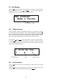
6.6
Display
In the normal operating mode the display provides information about the
current settings of the connected PAM G2. You can choose among three
different formats.
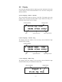
a) Set Display: Name & Values
This is the default setting on delivery of the EPC. The display shows the
number of the currently selected PAM G2 input channel, the fully userdefinable channel name and its settings.
channel name
channel number
1 Pick-Up One
38dB 47kΩ 200pF
gain
input resistance
input capacitance
b) Set Display: Values only
The display shows the number of the currently selected PAM G2 input
channel and its settings.
channel number
1 GAIN RES. CAP.
38dB 47kΩ 200pF
gain
input resistance
input capacitance
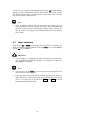
c) Set Display: Name only
The display shows the number of the currently selected PAM G2 input
channel and the fully user-definable channel name
channel number
channel name
Input 1
Pick-Up One
19
As soon as you enter the setup menu by pushing the set key, the display
changes to show information related to the selected menu item. For further display details refer to the description of each menu item in section
'Setup menu' starting from page 26.
Note
·
After 10 minutes without any user interaction the 'display saver' is
invoked automatically. The display then shows only the number and
the name of the currently selected input channel. Please refer to section 'Set Dim Level' on page 30 for further information on the 'display
saver' mode.
6.7
Input selection
Push the key up or down on the front panel of the EPC, to select the desired input channel of the PAM G2. Push the down key to select Input 1
and the up key for Input 2.
Important
·
If your PAM G2 is equipped with only one channel, the input selection is disabled and channel switching is not possible. In this case,
only Input 1 is available.
Note
·
You can also use the input key on the front panel of the PAM G2 to
select the active input channel.
·
Using the Audionet System Remote Control Harmony One, select an
input channel by simply pressing the corresponding key (see section
'Screen 1' on page 24), or use the keys Vol+ and Vol- to switch
between the two input channels.
20
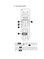
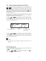
7
Audionet System Remote Control
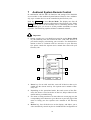
In combination with the EPC all functions and settings of the PAM G2
are accessible via the Audionet System Remote Harmony One. Additionally, up to 14 other devices can be controlled by the Harmony One.
Press key Devices to enter Device Mode. The display now lists all
devices included in the current configuration of the Harmony One. Select
EPC from the list to set the Harmony One to controlling the EPC. The
Device Mode gives you access to all the possible commands to control
your EPC. The following explains all these commands in detail.
Important
·
During everyday use, you should never need to use the Device Mode
of your Harmony One, but control the EPC (and other devices of
your audio setup) by customizing your Activities. For detailed information on how to customize and use Activities on your Harmony
One please consult the separate user's manual that came with your
Harmony One.
1
2
My Activities:
Mi 14:51
1/2 pages
Listen to CDs
Watch a DVD
3
3
CD with VIPG3
Options
Devices
4
5
1
Power key for use with Activities, turns off all devices that are included into the current Activity. See separate user's manual of Harmony One.
2
Depending on the operational mode, the touch screen of the Harmony One shows a list of Activities or Devices, help or infrared commands and any available listing.
3
If a menu or listing stretches over more than one screen page, use the
corresponding arrow buttons to go to the next or previous page of the
menu or listing (see also separate user's manual of the Harmony
One).
4
Devices key, lists all the devices on the display, and allows you to
select and directly control any device included in the configuration of
21
the remote control (see separate user's manual of Harmony One). Select EPC to enter Device Mode for controlling the EPC.
5
Activities key: Press this key to view a list of Activities you have
added. Press the button next to the Activity you want to select, and
the Harmony One will control your entertainment system (see separate user's manual of Harmony One).
Important
·
is only available for Activities. In Device
The Power key
Mode the Power key has no function.
·
Even without using an Activity, the user is able to control all
functions of the EPC using the Harmony One in Device Mode.
·
The keys described below to control the EPC refer to the factory
default programming of the Audionet System Remote Control
Harmony One. Understandably, any changes done to this setup
by the user cannot be discussed here.
Tip
·
In order to switch the EPC on/off, without using an Activity, please
use the keys Power Toggle , Power On and / or Power Off
on screen 2 (see section 'Screen 2' on page 25). Of course, it is possible to control the EPC without any Activity, but to tap the full potential of the Harmony One you need to configure Activities customized to your needs (please refer to separate manual of the remote
control Harmony One).
Note
·
Please read the separate user's manual to your Audionet System Remote Control Harmony One. Activities, Devices and Device Mode as
well as customizing the remote control are discussed there in detail.
22
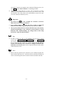
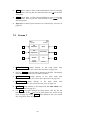
7.1 Key assignment EPC
EPC:
Mi 14:51
1/2 pages
Set
Resistance.
Show
Set
Capacitance
Dim Display
Set Gain
Set
Current
Activity
Devices
2
1
3
4
5
1
Use key Menu to navigate through the setup menus. This key has
the same function as key set on the front panel of the EPC (see section 'Setup menu' on page 26) or the key Set on screen page 1 (see
section 'Screen 1' in page 25).
2
Use the key Info to activate the 'Show' function of the EPC. The
screen saver (if active) will be interrupted and the display shows the
settings of the active PAM G2 input channel. This key has the same
function as Show on screen page 1 (see section 'Screen 1' on page
24)
23
3
Vol+ selects input 2 of the connected PAM G2, also for selecting
setup options. This key has the same function as key up on the EPC
front panel.
4
Vol- selects input 1 of the connected PAM G2, also for selecting
setup options. This key has the same function as key down on the
EPC front panel.
5
Digit keys for direct input selection (see section 'Input selection' on
page 20).
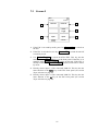
7.2
Screen 1
EPC
Mi 14:51
1/2 pages
1
Set
Resistance
Show
2
3
Set
Capacitance
Dim Display
4
5
Set Gain
Set
6
Current
Activity
Devices
1
Set Resistance jumps directly to the setup menu item
SET RESISTANCE (see section 'Set Resistance' on page 28).
2
The key Show actives the 'Show' function of the EPC. The display
shows the settings of the active PAM G2 channel.
3
Set Capacitance jumps directly to the setup menu item
SET CAPACITANCE (see section 'Set Capacitance' on page 28).
4
Dim Display
jumps directly to the setup menu
Set Dim Level (see section 'Set Dim Level' on page 30).
5
Set Gain jumps directly to the setup menu item SET GAIN (see
section 'Set Gain' on page 30).
6
Use Set to navigate through the setup menus. This key has the
same function as the set key on the front panel (see section 'Setup
menu' on page 26) or key Menu of the Harmony One (see section
'Key assignment EPC' on page 23).
24
item
7.3
Screen 2
EPC
Mi 14:51
2/2 pages
1
4
Power Off
2
Power
Toggle
3
Input 1
Input 2
5
Current
Activity
Devices
Power On
1
If the EPC is in stand-by mode, press key Power On to switch on
the unit.
2
If the EPC is switched on, use key Power Off to switch the unit off
to stand-by mode.
3
Use Power Toggle to switch on/off the EPC. This key has the
same function as the power key on the front panel. If the EPC is in
stand-by mode, Power Toggle switches on the unit. If the EPC is
already switched on, Power Toggle switches off the unit to standby mode.
4
Directly selects input 1 of the connected PAM G2. This key has the
same function as the down key on the EPC front panel (see section
'Input selection' on page 20).
5
Directly selects input 2 of the connected PAM G2. This key has the
same function as the up key on the EPC front panel (see section
'Input selection' on page 20).
25
8
Setup menu
To adjust the EPC and PAM G2 to your preferences, please use the setup
menu.
Push the set key on the front panel of the EPC for less than two seconds
to go to the first item of the setup menu. Navigate to the next menu item,
by pushing the set key again for less than two seconds. Below is a list of
all menu items of the setup menu.
After the last menu item you will leave the setup menu automatically. Of
course, you may leave the setup menu from each menu item by holding
the set key down for longer than two seconds. The EPC will return to the
normal operating mode.
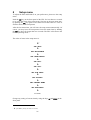
The order of items in the setup menu is:
ê*1
SET GAIN
ê
SET RESISTANCE
ê
SET CAPACITANCE
ê
SET Rext
ê
SET Cext
ê
SET DIM LEVEL
ê
SET DISPLAY
ê
SET CHANNEL NAME
ê
SET AUTOSTART
ê
exit menu
Change any setting of a menu item by using the keys up and down on the
front panel.
*1
ê = push set key shortly (less than two seconds)
26
Tip
·
All settings of the setup menu can be dealt with by using the keys of
the front panel. However, if you prefer to change settings from the
comfort of your listening chair, please use the Audionet System Remote Control Harmony One. For more information about the remote
control and its usage see section 'Audionet System Remote Control' on
page 21.
Note
·
If you make no adjustments for longer than 12 seconds the EPC will
automatically leave the setup menu and return to normal operating
mode.
·
While you are in the setup menu the display brightness is set to 100%
for better readability. After leaving the setup menu the display
brightness is automatically reset to its user selected level.
·
If you power down the EPC to stand-by mode all settings are stored
automatically in the non-volatile memory of the unit. Even after disconnecting from mains the EPC will still remember your settings.
In the following all options of the setup menu are explained in detail.
8.1
Set Gain
Push the set key on the front panel once for less than two seconds to select the gain of the connected PAM G2's active channel using the keys up
and down. You can choose between the supported gain values of the
PAM G2: 38 dB, 48 dB, 58 dB or 68 dB. The display shows the number
of the currently active input channel and the selected gain value.
SET GAIN:
Ch.1
48dB
active channel number.
gain in dB
Important
·
Excessive gain could lead to overdrive and distortion!
27
Set the gain so that the output voltage of the PAM G2 UPAMG2 is approx.
1...1.5 V. With a given pick-up voltage Upick-up the gain calculates to:
U PAMG2
U pickup
= gain .
Refer to the following table to get the gain in dB from the calculated gain
factor:
Gain in dB
38
48
58
68
Gain factor
80
250
800
2500
Example:
Output voltage: UPAMG2 = 1.2 V
Pick-up voltage: Upick-up = 1.5 mV
Gain:
8.2
1.2V
1.5 mV
= 800 Þ set the PAM G2 to 58 dB
Set Resistance
Push the set key on the front panel twice for less than two seconds to
select the input resistance of the connected PAM G2's active channel.
Now use keys up and down to adjust the input resistance. You can
choose between the following values: 100 Ω, 150 Ω, 470 Ω, 1 kΩ, 23 kΩ,
47 kΩ and 69 kΩ.
For typical resistance values of miscellaneous pick-up see section
'Typical setups' on page 35.
SET RESISTANCE:
Ch.1
47kΩ
active channel number.
8.3
input resistance (Ω or kΩ)
Set Capacitance
Push the set key on the front panel three times for less than two seconds
to select the input capacitance of the connected PAM G2's active channel.
Now use keys up and down to adjust the input capacitance You can
choose between the following values: 100 pF, 150 pF, 320pF and
420 pF.
28
This setting is critical for MM systems only. For MC pick-up systems the
input capacitance should be set to 100 pF.
SET CAPACITANCE:
Ch.1
200 pF
active channel number.
8.4
input capacitance (pF)
External input resistance (Set Rext)
If fine adjustments of the input resistance via the parallel RCA ports 19
or 20 on the back panel of the PAM G2 are made (see section 'Further
adjustments' on page 35), you can enter the value of the external resistor
in the EPC setup. In normal operation mode the resulting input resistance
is calculated and shown in the display. Push the set key on the front panel
four times for less than two seconds to enter the value of the external
resistor.
The display shows the number of the connected PAM G2's active channel
and the current value of the external input resistor. A cursor points to the
editable character of the resistance value.
Use the keys up and down on the front panel to select the desired character. Hold set key down for longer than two seconds to move the cursor
one step to the right. After the last position the cursor wraps around and
starts at the first position again.
SET Rext: 0000 Ω
Ch.1
▲
active channel number.
cursor
value of the external
input resistor
Note
·
At the last character the keys up and down switch only between the
two options Ohm (Ω) and Kiloohm (kΩ).
29
8.5
External input capacitance (Set Cext)
If fine adjustments of the input capacitance via the parallel RCA ports
19 or 20 on the back panel of the PAM G2 (see section "Further adjustments" on page 35) are made, you can enter the value of the external
capacitor in the EPC setup. In normal operation mode the resulting input
capacitance is calculated and shown in the display. Push the set key on
the front panel four times for less than two seconds to enter the value of
the external capacitor.
The display shows the number of the connected PAM G2's active channel
and the current value of the external input capacitor. A cursor points to
the editable character of the capacitance value.
Use the keys up and down on the front panel to select the desired character. Hold set key down for longer than two seconds to move the cursor
one step to the right. After the last position the cursor wraps around and
starts at the first position again.
SET Cext: 0000 pF
Ch.1
▲
active channel number.
cursor
value of the external
input capacitor
Use the keys up and down on the front panel to select the desired character. Hold set key down for longer than two seconds to move the cursor
one step to the right. After the last position the cursor wraps around and
starts at the first position again.
Note
·
The capacitance range is limited to picofarad (pF) and can not be
changed.
8.6 Set Dim Level
To adjust the brightness of the display on the front panel of the EPC push
the set key five times less than two seconds.
Now use keys up and down to select the desired brightness. Key up increases, key down decreases the brightness.
30
SET DIM LEVEL:
██████______ 50%
current brightness level in %
Additionally, the display shows the current brightness level in percent
and by a bar of corresponding length:
Important
·
Long-term usage of the display set to maximum brightness (setting 100%) may cause extended signs of wear resulting in a decay
of contrast or brightness of individual dots in the display. Do not
use the display with a brightness set higher than the factory default of 50% over a longer period of time!
Note
·
Is the brightness set to Off the display is only on during setup adjustments or input selection. It switches off automatically several seconds after the last user entry.
·
The EPC activates the 'display saver' automatically after 10 minutes
without any user entry.
·
During active 'display saver', the display shows only the number and
the name of the currently selected input channel. The display brightness is always reduced to 25%, and the location of the information
text will change randomly every 12 seconds to prevent any 'burn-in'
effect of the display.
·
The 'display saver' is de-activated and the display returns to its normal mode as soon as any user entry is detected
·
The user cannot switch off the automatic 'display saver' function!
Tip
·
Get to the option Set Dim Level at anytime using the key
Dim Display on screen page 1 of the Audionet System Remote
Control Harmony One (see section 'Screen 1' on page 24). Use keys
Vol- and Vol+ to select desired brightness.
31
8.7 Set Display
Push the set key seven times for less than two seconds, to select the display format. Now use keys up and down to switch between the three
available formats (see section 'Display' on page 19).
SET DISPLAY:
Name & Values
selected display format
8.8
Channel name
You can assign a fully user-definable name up to 14 characters in length
to each of the two input channels of the connected PAM G2. Push the set
key on the front panel eight times. The display will then show the number
of the currently selected input channel and the assigned channel name.
The cursor in the display marks the character you now may alter.
Use the keys up and down on the front panel to select the desired character. Hold set key down for longer than two seconds to move the cursor
one step to the right. After the last position the cursor wraps around and
starts at the first position again.
1 Pick-Up One
▲
channel number
8.9
cursor
channel name
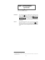
Set Autostart
Push the set key nine times for less than two seconds to get to the option
Autostart.
Push the up key on the front panel to activate the Autostart function. If
you like to deactivate the Autostart function push down key.
32
SET AUTOSTART:
active
state of the Autostart function
disabled
The Autostart function is disabled. After switching on the
mains switch 1 on the back panel, the EPC enters the
stand-by mode. You have to use the power key on the
front panel of EPC / PAM G2 or keys Power On or
Power Toggle on the Audionet System Remote Control Harmony One to switch on the unit into normal operating mode*).
active
The Autostart function is active. As soon as you connect
the EPC to mains (i.e. use the mains switch 1 on the
back panel) the unit starts up automatically to normal operating mode. Use this setting for timer controlled operations.
*)
or switched on/off by Activities on the Audionet System Remote Control; see separate user's
manual Harmony One
33
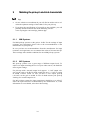
9
Matching the pick-up's electrical characteristic
Tip
·
On our website www.audionet.de you will find an online tool to calculate the optimum settings of the PAM G2 for your pick-up.
·
If you have the specifications of your pick-up not available, you will
probably find the technical data at the following website:
www.vinylengine.com/cartridge_database.php.
9.1.1
MM Systems
For MM pick-up systems set the gain to 38 dB. For the settings of input
resistance and capacitance please refer to the recommendations of the
manufacturer of your pick-up.
In case you have no recommendations from the manufacturer for input
resistance and capacitance we recommend the values 47 kW and 200 pF.
These settings offer suitable conditions for most MM pick-up systems.
9.1.2
MC Systems
MC pick-up systems cover a great range of different output levels. To
achieve an output matching the level of your other sources, the PAM G2
offers 4 gain settings:
For pick-ups with a 'normal' output level (approx. 1...2 mV output voltage) set the gain to 58 dB. For high output pick-ups (3...5 mV) a setting
of 48 dB is better suited. In case you have a low output pick-up
(<0.8 mV) set the gain to 68 dB. In case of doubt assume your pick-up
working at a 'normal' output level.
For MC pick-up systems the input capacitance should be set to 100 pF.
Select the input resistance recommended by the manufacturer or, if the
information is not available, select the 100 W setting.
34
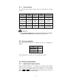
9.1.3
Typical setups
The following table outlines typical setups for miscellaneous pick-up
systems:
System
Output
voltage
Gain
Input
resistance
Input capacitance
Low Output MC
< 0.6 mV
68 dB
100 W
110 pF
MC
~ 1...2 mV
58 dB
High Output MC
~ 3...5 mV
48 dB
100...470 W
110 pF
MM
~ 4...6 mV
48 dB
47...68 kW
160...220 pF
High Output MM
> 6 mV
38 dB
47...68 kW
160...220 pF
Important
·
For optimum adjustment to your pick-up follow the recommendations of the manufacturer! If necessary ask your dealer.
9.2 Factory defaults
Upon delivery of the PAM G2 to following settings are configured by
default:
Gain
38 dB
Input resistance
47 kW
Input capacitance
200 pF
This configuration is suitable for most MM pick-up systems.
9.3 Further adjustments
9.3.1
Adjusting the input capacity
If the selectable capacity of C0 = 420 pF is not enough or the required
capacity can not be selected, use an external capacitor to get the required
value. Connect an additional high quality capacitor Cext to the input
C/R ext. 15 and 16 using a RCA plug to increase the input capacity. In
this case the capacities are added together.
35
Example:
If a capacity of C = 500 pF is needed, select the base capacity of
C0 = 420 pF. Then add an additional capacitor of CEXT. = 82 pF to the
input C/R ext. 15 or 16 to get the required input capacity of 500 pF.
Note
In the above example the arithmetically resulting value of 80 pF was
replaced with the suitable capacitor of 82 pF from commonly available
standard E12 series.
9.3.2
Resistance reduction
If the required input resistance is less than the minimum selectable base
resistance of R0 = 100 Ω or the needed resistance value is not available,
use an external resistor to get the required value. Connect an additional
high quality resistor Rext to the input C/R ext. 15 and 16 using a RCA
plug to reduce the input resistance. Attention! The reciprocal values of
the resistors are added, so the input resistance is reduced!
R=
R0 * Rext
1
Þ Rext =
1 1
R0 + Rext
R R0
Example 1:
If a resistance of R = 33 Ω is needed; choose the base resistance to
R0 = 100 Ω, and add external resistor of Rext = 50 Ω.
Rext =
1
1
1
33 100
W = 50 W
Example 2:
If a resistance of R = 200 Ω is needed; choose the base resistance to
R0 = 330 Ω, and add external resistor of Rext = 510 Ω.
Rext =
1
1
1
200 330
36
W = 510 W
10 Security advice
Important
·
Avoid packaging material, especially plastic bags, coming into children's hands!
·
Store and operate the unit in a dry room at a reasonable room temperature only!
·
Avoid moisture, any liquids, dirt or small objects getting into the
unit!
·
Set up the unit in a sufficiently ventilated environment!
·
Do not cover the unit!
·
Do not open the unit. Unauthorised opening will void warranty!
·
Do not short-circuit the outputs!
·
During connecting or removing the PAM G2 to/from sources and/or
power amplifiers all units have to be switched off to prevent damage
of the PAM G2 or any of the other connected units.
¨ Use dry cloth for cleaning!
¨ Do not place the EPC directly under/above or to the left of the
PAM G2! Otherwise the transformers in the EPC might induce humming into the signal path of the PAM G2.
37
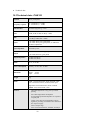
¨ Technical data
10.1 Technical data - PAM G2
Function
phono preamplifier
Frequency response
40 – 30.000 Hz (+/- 0.2dB)
18 – 80.000 Hz (+/- 1.0dB)
Subsonic filter
4nd order high pass fg = 8 Hz
Gain
38 dB, 48 dB, 58 dB, 68 dB (@ 1 kHz)
SNR
< -103 dB @ 1 kHz (Gain = 38 dB)
< -83 dB @ 1 kHz (Gain = 58 dB)
Inputs
2 pair WBT RCA jacks, gold plated
2 pair WBT RCA jacks, gold plated, for additional
impedance adjustment
Input impedance
selectable by EPC
Output
1 pair WBT-NextGen line, gold plated
1 pair XLR (Neutrik) , gold plated
Output impedance
24 Ohm real (RCA)
94 Ohm real (XLR)
Mains
230 V, 50..60 Hz
Power consumption
Stand-by < 0.5W, max. 40 Watt
Dimensions
Width: 430 mm
Height: 70 mm
Depth: 310 mm
Weight
9 kg
Finish
Front: : brushed aluminium, black anodised, white
print or aluminium 'nature', anodised, black print
Top cover: brushed aluminium, black anodised
Chassis: steel, black coated, 2 mm
Features
-
individual adjustment to any pick-up without
opening
-
active dual stage RIAA de-emphasis
-
no integrated operational amplifiers or capacities
in signal path
-
14 fast, purely discrete realized MOS voltage
regulators providing accumulator-like characteristics of power supply
-
Class A output stage
-
100 VA toroid transformer, shielded, 40.000 µF
38
capacity
-
DC-free outputs
-
FET inputs, no bias current
Errors and omissions excepted. Specifications and design are subject to changes without prior notice.
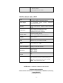
10.2 Technical data - EPC
Type
ultra low noise, highly stable and constant power
supply and controller for Audionet PAM G2
Power supply
two encapsulated 100VA
and 260.000 mF capacity
Circuitry
reference voltage sources for pos. and neg. analog
voltages using discrete Audionet voltage regulators
(MOS)
Connections
7-pin socket for connecting the PAMG2
2 D-Sub 25 (Phone Control Bus)
2 Audionet Link, optical (TosLink)
Output voltage
±24.00 V for analog sections,
approx. +5V for digital and control sections
Stability
±0,01 V at 0,5 A
Noise
-144 dB or 1,5 mVeff at 0 Hz to 22 kHz
Mains
220 V…240 V, 50…60 Hz
Power consumption
Stand-by < 0,5W, max. 50 Watt
Dimensions
Width: 430 mm
Height: 70 mm
Depth: 310 mm
Weight
9 kg
Finish
Front: : brushed aluminium, black anodised, white
print or aluminium 'nature', anodised, black print
toroidal
transformers
Top cover: brushed aluminium, black anodised
Chassis: steel, black coated, 2 mm
Errors and omissions excepted. Specifications and design are subject to changes without prior notice.
audionet is a trademark of Idektron GmbH & Co KG
Engineered and produced by:
Idektron GmbH & Co. KG, Herner Str. 299, Gebäude 6, 44809 Bochum, Germany
www.audionet.de
[email protected]
39