1
International Journal of Computer Applications (0975 – 8887)
International Conference on Information and Communication Technologies (ICICT- 2014)
5. VALIDATION AND EXPERIMENTAL
RESULTS
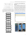
Fig6: Timing Waveform of Parallel 6800-Series Interface
There is sequence of operation to be performed to initialize the
TFT LCD. SSD1289 driver controller contains several command
registers. It’s necessary to write those register in sequence,
describing desired display mode, power setting, mode of interface
etc. Fig 7 gives the work flow of initialising of TFT LCD display
module.
The validation is performed in two steps; first touch screen
controller is implemented on target board using Crossware
Embedded Development Studio as explained in section IV. Its
response is being verified on windows hyper terminal connected
via two wire Rx and Tx ports of UART0 of the host controller.
Fig 8 shows the output values obtained on windows hyper
terminal for touch event as its co-ordinate values and untouch
event is represented by zeros. For the touch event the X and Y
coordinates are found as explained with the help of fig 5. First,
the voltage gradient is created for X axis and coordinate value is
converted using in-built ADC. Repeated same procedure for Y
axis coordinates estimation by creating voltage gradient to Yaxis. The obtained values are send to windows hyper terminal
through UART protocol and verified for various touch positions.
Fig 9 gives the implementation result for resistive touch sensor
based graphics plotter. The graphics is reproduced and displayed
on TFT LCD display as user writes over touch screen.
Power Supply setting
Display Control Setting
Set Oscillation Start Bit
Set Display ON Bit of
Command Register R07h
Exit from Sleep Mode by
Setting Sleep Mode Exit
Bit of R10h
Fig 8: Windows hyper terminal window
Wait for 30ms
Entry Mode Setting
LCD Driver and AC Setting
Write Data into Graphic
Display Data Ram
(GDDRAM)
Display ON
Fig 9: Implementation Result
Fig 7: LCD Power ON Sequence
40